
Submitted:
12 January 2026
Posted:
13 January 2026
You are already at the latest version
Abstract
Sub-terahertz (sub-THz) frequencies are at the spotlight in the undergoing development of sixth-generation (6G) wireless communication systems, offering ultra-high data rates and low latency for rapidly emerging applications. However, employment of sub-THz frequencies introduces strict propagation challenges, including free-space path loss and atmospheric absorption, which limit coverage and reliability. To address these issues, highly directional links are required. The conventional beam shaping solutions such as refractive lenses and parabolic mirrors are bulky, heavy, and costly, making them less attractive for compact systems. Diffractive optical elements (DOEs) offer a promising alternative by enabling precise wavefront control through phase modulation, resulting in thin, lightweight components with high focusing efficiency. Employing the fused deposition modelling (FDM) using high impact polystyrene (HIPS), allows cost-effective fabrication of DOEs with minimal material waste and high diffraction efficiency. This work investigates the beam-shaping performance of the FDM-printed structures comparing DOEs and spherical refraction-based structures, wherein both are aiming for application in sub-THz communication systems. DOEs exhibit clear advantages over classically employed solutions.
Keywords:
diffractive optical elements
; beam shaping
; sub-terahertz band
; high impact polystyrene
; high-frequency communication
; fused deposition modelling
1. Introduction
The sub-terahertz (sub-THz) frequency range is considered to be a key enabler for next-generation wireless communication systems such as 6G [1,2,3]. High carrier frequencies, typically employing the 60 GHz – 300 GHz range, provide very wide bandwidths, allowing high data throughput, which is essential for the ever-growing number of consumers and devices, as well as enabling massive Internet of Things (IoT) platforms [4,5]. For example, the unlicensed 60 GHz band offers several gigahertz of spectrum, enabling multi-gigabit wireless links in standards like IEEE 802.11ad/ay [6]. However, operating at such high frequencies introduces free-space path losses and atmospheric absorption, which significantly reduce signal strength and coverage [7,8]. Free-space path loss increases with frequency – at 60 GHz it is approximately 20 dB –- 30 dB higher compared to currently most employed microwave bands (e.g., 2 GHz -– 5 GHz). In addition, the 60 GHz band experiences atmospheric absorption on the order of 10 dB –- 15 dB per kilometer [9,10]. To mitigate these losses, highly directional free-space transmission links between the emitter and receiver parts of the network are essential. To guarantee high intensity carrier beam propagation, it is important to enhance the emitter directivity properties. [11,12].
One of the most effective ways to improve directivity and extend the effective propagation distance is optical beam collimation, allowing to maintain concentrated irradiance path in free space. Traditional solutions such as refractive lenses and parabolic mirrors used for beam focusing are often heavy, bulky, and expensive [13,14]. Thick lenses may also add extra material-dependent absorption losses and in combination with their size make integration into compact systems difficult and less efficient. Diffractive optical elements (DOEs) offer a promising alternative for beam control [13,15,16,17]. These components use wavefront engineering to control phase via constructive interference, enabling focusing, beam steering, and wavefront tailoring with millimeter-scale thickness and low mass elements [18,19,20,21]. They also enable the achievement of lower F-number, ensuring close focusing with a wide aperture, required for integration into compact devices. Recent advances in additive manufacturing, particularly fused deposition modelling (FDM) using High Impact Polystyrene thermoplastic material (HIPS) [22], demonstrated cost-effective production of DOEs with minimal material waste. It has been shown that 3D-printed DOEs can provide high focusing efficiency and compact designs, making them suitable for complex sub-THz communication systems [20,23,24,25]. Printable diffractive optics can be a great beam shaping alternative, applicable in sub-THz communication field. It allows to maintain or even increase the efficiency of optical systems, while decreasing their physical parameters, weight and production cost. These characteristics are particularly relevant for scenarios requiring multiple highly directive links deployed in close proximity, such as dense urban access points and indoor network infrastructures. This allows for integration opportunities into small, easily integrable communication devices, which is relevant for production of densely packed 5G/6G stations in urban areas [11].
In this work, we focus on the design and modeling of FDM-printed diffractive elements for sub-THz communication systems. We analyze the potential use of Fresnel lenses and its variations to improve link directivity, reduce propagation losses, and enable scalable integration into next-generation wireless networks. Finally, experimental results are also provided, demonstrating link directivity improvements over uncollimated beam as well as a comparison to conventional spherical lens.
2. Materials and Methods
The present investigation focuses on the development of DOEs designed to collimate electromagnetic radiation emitted by a commercial 60 GHz source. Beam shaping is achieved using a diffraction-based element, which is configured employing a non-paraxial phase-surface design equation, expressed as
Here k is a wavenumber, f - focal length, x and y phase surface coordinates, and - focal point coordinates. The required phase-shift for the calculated profile of the structure was achieved by varying thickness of the structure at each point of the phase surface. HIPS was selected for the fabrication due to its compatibility with simple and cost-efficient 3D printing method as well as refractive index of [26], allowing to achieve phase modulation by increasing the thickness of the diffractive element by 7 mm. Designs have been fabricated employing Creality K1 (Creality 3D Technology Co., Ltd., Shenzhen, Guangdong, China) extrusion 3D printer. Despite being compatible with the smaller ones, printer nozzle with a diameter of 0.4 mm was chosen intentionally to reduce the fabrication time and in turn the possibility of printing errors. The selected nozzle diameter is considered small enough, since it is an order of magnitude smaller than the wavelength of interest, making the surface roughness effectively invisible to sub-THz radiation. A vertical resolution of 0.1 mm was set to ensure good quality in every layer. A printing infill of 100% was used to ensure a continuous optical path within the lens material, which is crucial for the lens performance. The printing of one component takes hours. The elements were designed in the shape of 12 mm × 12 mm square with the supporting frame of 1.5 mm width. The elements were printed on the HIPS base of 2 mm thickness. Additional holes were drilled for the mounting of the lens as revealed at Figure 1b).
Commercial Peraso PRM2141X mmWave Module featured by beam divergence was employed as the emitter, implying creation of the lenses with optimal lens number . A frequency of 60 GHz was initially chosen, although the emitter is designed to operate across the 57 GHz - 71 GHz range covering 13 channels according to the 802.11ad. Such capabilities of the emitter facilitates future studies related to the compatibility of the proposed and existing solutions across the whole range of operation. The same module, but without any beam-shaping solution was used as a detector in the setup.
The fabricated elements have been characterised by measuring the spatial signal distribution (intensity dependency on the angle). This was performed in anechoic chamber environment to avoid any external noise and reflection from different surfaces. The chamber dimensions are 8.4 m × 4.6 m × 3.7 m. Conforming to the IEC EN 61000-4-3 standard for electromagnetic emission measurement the anechoic chamber provides perfect environment for the research of next generation communication systems and their components. Fabricated lenses were rigidly mounted on the 60 GHz emitter at the focal distance of the structure (the focal distance has been checked upon measuring the same setup adjusting the distance between the source and the sample). The system was placed on angle-controlling tripod, covering 180 degrees of the horizontal plane. The detector was positioned at 0 degree angle at the same height and kept at a constant position. The distance between the source and the detector was kept constant at m. By rotating the emitter-lens system a full 180 degree beam profile was recorded. Rotation in the vertical plane was not performed due to lens and emitter antenna array symmetry. The experimental setup is displayed in Figure 1a).
3. Results and Discussion
In order to ensure the correctness of the design, prior to the fabrication, the beam-shaping abilities of the generated structures have been theoretically checked. This was done by employing FDTD method provided by the CST Studio Suite software. Figure 2a) presents simulations of the beam-shaping element in which the refractive index of the material is varied. During these simulations the design of the structure has been adjusted to account for the changed refraction index. The refractive index was varied over the range from 1.3 to 1.7 to account for the limited accuracy of the TDS-based measurement method at the 60 GHz operating frequency, as the TDS characterization system specifies reliable performance only down to 100 GHz. The simulations reveal that beam-shaping structure fabrication is possible in considerably wide range of the refractive index, however, a significant impact on the electric field strength at the focal point exists at low refraction indexes. Electric field strength change by approximately 12% has been observed for the refraction index change of . It is additionally revealed at Figure 2b), that an increase of the lens cross-sectional width (the non-optical, volumetric portion used for mechanical support rather than focusing) shifts the focal point slightly toward the lens, but the displacement is negligible and does not influence the radiation intensity.
The detailed modelling analysis lead to a selection of optimal Fresnel lens parameters for collimating the emitter beam. A lens diameter of 12 cm and a mounting-base thickness of 2 mm were chosen, resulting in an effective average lens thickness of 9 mm. As revealed at Figure 3, mm and mm has been observed. The Fresnel lens design yielded a focal length of 54 mm, corresponding to an F-number of F# = 0.45. For comparison with the non-paraxial diffractive design, a conventional refraction-based spherical lens was also designed and fabricated. A similar focal length of 50 mm was selected for this lens; however, the resulting F-number was higher, at F# = 0.74.
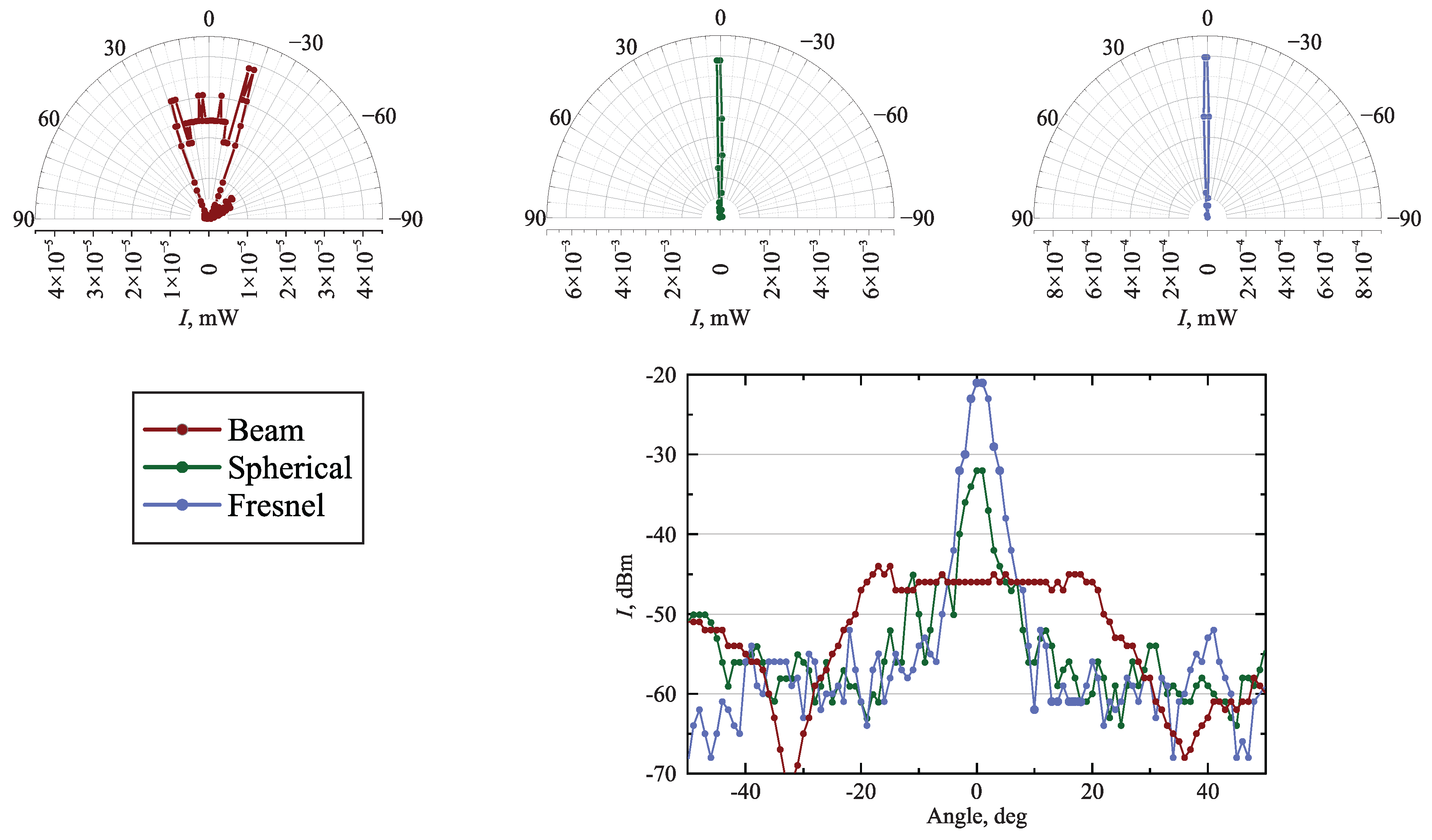
Main experimental results consist of detailed emitter beam directivity measurements incorporating conventional spherical lens and a wide-aperture Fresnel lens. The acquired angular beam dependencies for the bare emitter or the system of emitter enhanced with either spherical either Fresnel lens are presented in Figure 4. The performance of the beam-shaping solution is compared in terms of both the spatial profile of the collimated beam and its intensity at the target direction e.g. intensity. Considering the spatial profile, both the spherical and Fresnel lenses exhibit a significant reduction in the FWHM compared to the directivity of the bare emitter (FWHM of the bare emitter was found to be ). However, the difference of the collimated beam width between the two lenses was found to be considerably small: Spherical lens resulted in FWHM of compared to ) of the Fresnel lens. This indicates that the phase-domain beam-shaping mechanism in the fabricated Fresnel lens achieves an efficiency comparable to that of conventional refraction-based lenses. The advantage due to lower absorption of material of the proposed diffractive beam-shaping solution, arises comparing the target intensity of the lenses. In the case of Fresnel lens a distinct enhancement is observed, compared to the classical spherical lens. The measured beam intensities between the two lenses differ by more than one order - 0.64 W for the spherical element and 8 W for the Fresnel lens.
The pronounced increase in beam intensity can be attributed to two primary factors. The first is related to absorption of the emitted signal within the lens material. The effective thicknesses of the Fresnel and spherical lenses were 7 mm and 74 mm respectively. Considering the absorption coefficient of the HIPS polymer at 60 GHz to be 10 [27], the corresponding absorption losses were estimated at 6.8% and 32.3%. Although these values indicate a notable contribution to the overall intensity attenuation, lens absorption losses alone are insufficient to explain the experimentally observed differences between the two lenses. The second contributing factor concerns the numerical aperture (NA) of the collimating lens. When the emitter is positioned close to the lens, a high NA is essential to effectively capture the broad radial emission of the active 4x4 phased array antenna. The related F# values for spherical and Fresnel lenses are 0.74 and 0.45 thus in the latter case a more significant part of the emitter beam is captured. This may be the defining factor of the observed experimental result and the differences in intensity. Overall, a clear advantage of the diffraction based lens can be seen compared to the conventional, spherical lens design.
4. Discussion
The presented research is expected to significantly contribute to the extensively emerging new generation communication technologies including but not limited to the 60 GHz-based network. Until now, in newly-appearing commercially available products employment of diffractive beam shaping elements is found as vague or non-existent. The proposed research reveals promising possibilities for practical implementation of these components leading to 12.5 times more efficient beam shaping ( intensity wise), which in turn lays the foundation for enhanced implementation of the 6G+ communication technology in real-life applications.
The results indicate that the proposed approach maintains comparable beam-shaping efficiency while achieving a higher target intensity at , thereby outperforming classical refraction-based beam-shaping solutions. While similar beam spread is maintained, the Fresnel structure shows a pronounced increase in the on-axis () intensity exceeding one order of magnitude. This approach provides significant fabrication material savings as a result of the substantially decreased structural volume, thereby reducing the mass of the final solution. Finally, the use of diffraction-based beam-shaping solutions offers an additional advantage: since the element design is defined in the phase plane, it can be readily adapted to generate not only focused Gaussian beams but also other beam types, such as Bessel, Airy and related structured beams. This provides additional flexibility, leading to better adaptation and efficiency being employed in particular tasks.
In summary, the investigated diffraction-based lens revealed highly efficient beam collimation, surpassing the traditional refractive lens and promising opportunities to be employed in close-range high-speed/high-volume data transfer systems. Further development of such systems is considered crucial to further enhance currently emerging wireless communication networks in densely populated environments as well as considering the rapidly increasing amount of IoT solutions oriented for smart city and smart environment applications.
Author Contributions
Conceptualization, L.M. E.Š; methodology, V.C.; software, K.S.; validation, K.S. and S.D.; formal analysis, K.S.; investigation, K.S. and K.N.; resources, K.N.; data curation, K.N.; writing—original draft preparation, A.M., K.N., and S.D.; writing—review and editing, V.C.; visualization, A.M and V.C.; supervision, L.M.; project administration, L.M.; funding acquisition, L.M. All authors have read and agreed to the published version of the manuscript.
Data Availability Statement
Data underlying the results presented in this paper may be obtained from the authors upon reasonable request.
Acknowledgments
The authors would like to express their sincere gratitude to dr. Sergej Orlov for valuable, illuminating, and encouraging discussions related to diffractive optics and dr. Paulius Ragulis for the help with experimental measurements in the anechoic chamber.
Conflicts of Interest
The authors declare no conflicts of interest.
Abbreviations
The following abbreviations are used in this manuscript:
| DOE | Diffractive Optical Element |
| DOF | Depth Of Focus |
| FDM | Fused Deposition Modeling |
| FDTD | Finite-difference time-domain |
| FWHM | Full Width at Half Maximum |
| GHz | Gigahertz |
| HIPS | High Impact Polystyrene |
| NA | Numerical Aperture |
| TDS | Time Domain Spectroscopy |
| THz | Terahertz |
References
- Yeh, C.; Do Jo, G.; Ko, Y.J.; Chung, H.K. Perspectives on 6G wireless communications. ICT Express 2023, 9, 82–91. [Google Scholar] [CrossRef]
- Jiang, W.; Zhou, Q.; He, J.; Habibi, M.A.; Melnyk, S.; El-Absi, M.; Han, B.; Renzo, M.D.; Schotten, H.D.; Luo, F.L.; et al. Terahertz Communications and Sensing for 6G and Beyond: A Comprehensive Review. IEEE Communications Surveys & Tutorials 2024, 26, 2326–2381. [Google Scholar] [CrossRef]
- Atzeni, I.; Tejerina, G.R.d.L.; Berkvens, R.; Chen, H.; Conrat, J.M.; Guzman, M.F.D.; Desset, C.; Dörpinghaus, M.; Farhadi, H.; Fettweis, G.; et al. Sub-THz Communications: Perspective and Results From the Hexa-X-II Project. IEEE Open Journal of the Communications Society 2025, 6, 7495–7540. [Google Scholar] [CrossRef]
- Kleine-Ostmann, T.; Nagatsuma, T. A review on terahertz communications research. Journal of Infrared, Millimeter, and Terahertz Waves 2011, 32, 143–171. [Google Scholar] [CrossRef]
- Vettikalladi, H.; Sethi, W.T.; Ko, W. Sub-terahertz (THz) antenna for Internet of Things and 6G Communication. Frequenz 2021, 76, 177–184. [Google Scholar] [CrossRef]
- Niu, Y.; Li, Y.; Jin, D.; Su, L.; Vasilakos, A.V. A survey of millimeter wave communications (mmWave) for 5G: opportunities and challenges. Wireless Networks 2015, 21, 2657–2676. [Google Scholar] [CrossRef]
- Slocum, D.M.; Slingerland, E.J.; Giles, R.H.; Goyette, T.M. Atmospheric absorption of terahertz radiation and water vapor continuum effects. Journal of Quantitative Spectroscopy and Radiative Transfer 2013, 127, 49–63. [Google Scholar] [CrossRef]
- Taleb, F.; Alfaro-Gomez, M.; Al-Dabbagh, M.D.; Ornik, J.; Viana, J.; Jäckel, A.; Mach, C.; Helminiak, J.; Kleine-Ostman, T.; Kürner, T.; et al. Propagation of THz radiation in air over a broad range of atmospheric temperature and humidity conditions. Scientific Reports 2023, 13. [Google Scholar] [CrossRef]
- Rappaport, T.S.; Sun, S.; Mayzus, R.; Zhao, H.; Azar, Y.; Wang, K.; Wong, G.N.; Schulz, J.K.; Samimi, M.; Gutierrez, F. Millimeter Wave Mobile Communications for 5G Cellular: It Will Work! IEEE Access 2013, 1, 335–349. [Google Scholar] [CrossRef]
- Smulders, P. Exploiting the 60 GHz band for local wireless multimedia access: prospects and future directions. IEEE Communications Magazine 2002, 40, 140–147. [Google Scholar] [CrossRef]
- Ahamed, M.M.; Faruque, S. 5G network coverage planning and analysis of the deployment challenges. Sensors 2021, 21, 6608. [Google Scholar] [CrossRef]
- Singh, A.; Petrov, V.; Sen, P.; Jornet, J.M. Near-Field Terahertz Communications for 6G and Beyond: From concepts to realizations. IEEE Signal Processing Magazine 2025, 42, 106–125. [Google Scholar] [CrossRef]
- Siemion, A. Terahertz Diffractive Optics—Smart Control over Radiation. Journal of Infrared, Millimeter, and Terahertz Waves 2019, 40, 477–499. [Google Scholar] [CrossRef]
- Margheri, G.; Del Rosso, T. Tunable Device for Long Focusing in the Sub-THz Frequency Range Based on Fresnel Mirrors. Micromachines 2024, 15, 715. [Google Scholar] [CrossRef] [PubMed]
- Wentworth, F.; Wiltse, J.; Sobel, F. Quasi-optical surface waveguide and other components for the 100-to 300-Gc region. IRE Transactions on Microwave Theory and Techniques 1961, 9, 512–518. [Google Scholar] [CrossRef]
- Siemion, A. The Magic of Optics—An Overview of Recent Advanced Terahertz Diffractive Optical Elements. Sensors 2020, 21, 100. [Google Scholar] [CrossRef]
- Komorowski, P.; Kaluza, M.; Surma, M.; Siemion, A. 3D printed diffractive lenses operating at 1 THz. Lithuanian Journal of Physics 2023, 63. [Google Scholar] [CrossRef]
- Wiltse, J.C. Diffraction optics for terahertz waves. In Proceedings of the Terahertz for Military and Security Applications II. SPIE; 2004; Vol. 5411, pp. 127–135. [Google Scholar]
- Ivaškevičiūtė-Povilauskienė, R.; Kizevičius, P.; Nacius, E.; Jokubauskis, D.; Ikamas, K.; Lisauskas, A.; Alexeeva, N.; Matulaitienė, I.; Jukna, V.; Orlov, S.; et al. Terahertz structured light: nonparaxial Airy imaging using silicon diffractive optics. Light: Science & Applications 2022, 11. [Google Scholar] [CrossRef]
- Kaluza, M.; Komorowski, P.; Zagrajek, P.; Siemion, A. Terahertz focusing blazed diffractive optical elements for frequency demultiplexing. Advanced Optical Technologies 2023, 12. [Google Scholar] [CrossRef]
- Orlov, S.; Ivaškevičiūtė--Povilauskienė, R.; Mundrys, K.; Kizevičius, P.; Nacius, E.; Jokubauskis, D.; Ikamas, K.; Lisauskas, A.; Minkevičius, L.; Valušis, G. Light Engineering and Silicon Diffractive Optics Assisted Nonparaxial Terahertz Imaging. Laser & Photonics Reviews 2024, 18. [Google Scholar] [CrossRef]
- Stanaitis, K.; Čižas, V.; Bielevičiūtė, A.; Grigelionis, I.; Minkevičius, L. High-Impact Polystyrene Structured Light Components for Terahertz Imaging Applications. Sensors 2024, 25, 131. [Google Scholar] [CrossRef] [PubMed]
- Squires, A.D.; Constable, E.; Lewis, R.A. 3D Printed Terahertz Diffraction Gratings And Lenses. Journal of Infrared, Millimeter, and Terahertz Waves 2014, 36, 72–80. [Google Scholar] [CrossRef]
- Furlan, W.D.; Ferrando, V.; Monsoriu, J.A.; Zagrajek, P.; Czerwińska, E.; Szustakowski, M. 3D printed diffractive terahertz lenses. Optics Letters 2016, 41, 1748. [Google Scholar] [CrossRef] [PubMed]
- Komorowski, P.; Siemion, A.; Walczakowski, M.; Zagrajek, P. The Role of the Directivity of Various THz Detectors in Multiplexing Systems. Applied Sciences 2022, 12, 3545. [Google Scholar] [CrossRef]
- Stanaitis, K.; Redeckas, K.; Bielevičiūtė, A.; Bernatonis, M.; Jokubauskis, D.; Čizas, V.; Minkevičius, L. Study of the low-cost HIPS and paraffin-based terahertz optical components. Lithuanian Journal of Physics 2023, 63, 233–240. [Google Scholar] [CrossRef]
- Pérez-Escribano, M.; Márquez-Segura, E. Parameters Characterization of Dielectric Materials Samples in Microwave and Millimeter-Wave Bands. IEEE Transactions on Microwave Theory and Techniques 2021, 69, 1723–1732. [Google Scholar] [CrossRef]
Figure 1.
(a) Schematic representation of the experimental structure angular characterisation setup. The measurement was conducted in an anechoic chamber. The emitter and the designed element were rigidly mounted, and the assembly was positioned on an angle-controlled tripod. At the distance of 4.4 meters, detector - the same chip, but without any beam-shaping solution - has been placed. Angular intensity dependency has been achieved by rotating the source coupled with the element. (b) Photo of one of the fabricated Fresnel type lenses, thickness of the structure 7 mm. (c) Photo of the spherical lens, featured by the identical focal distance. Thickness of the structure 74 mm.
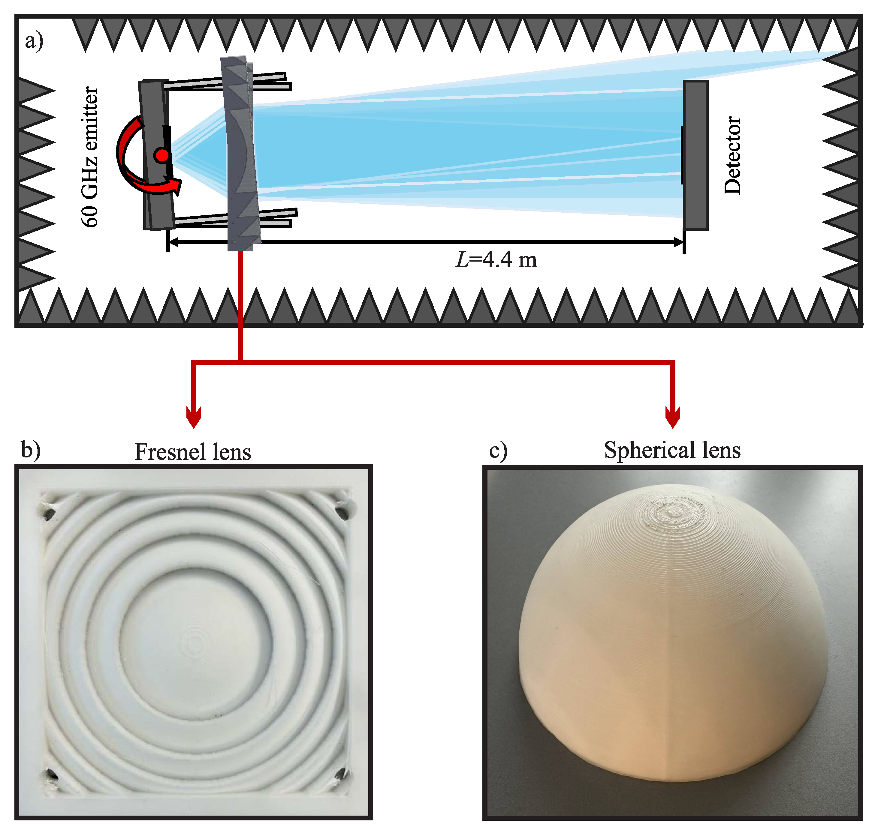
Figure 2.
Electric field strength intensity profiles along the optical axis for the structures of different refractive index (a) and base layer thickness (b). Refraction index sweep reveals beam-shaping abilities of the structures, fabricated from different materials of different refraction index. The efficiency decrease with the decrease of the refraction index is observed. Base layer thickness is shown to have insignificant effect on the beam-shaping abilities of the structure due to low absorption of the frequency range of interest in the material.
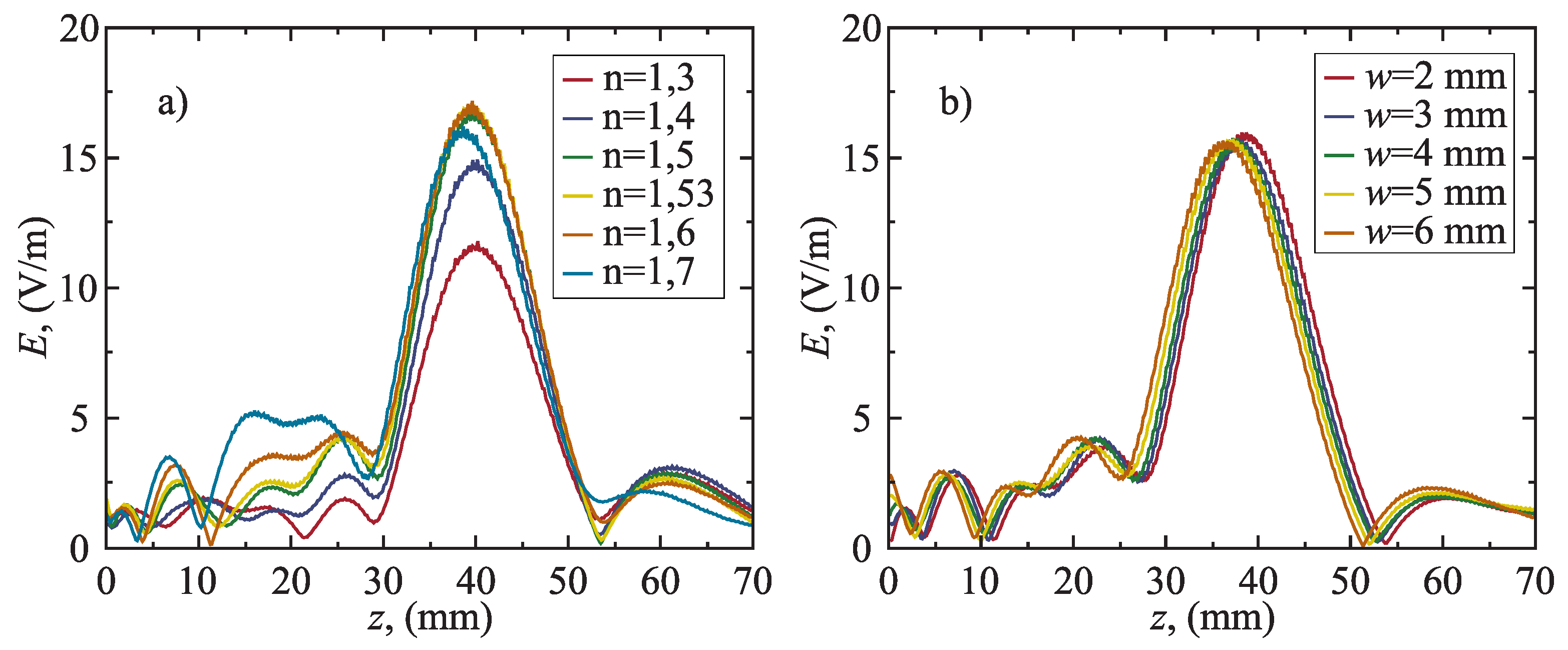
Figure 3.
Electric field strength distribution of the lens, selected for fabrication (diameter 12 cm, designed focal distance 50 mm). Distributions are revealed for the x-z plane (a) and for main lines of interest: perpendicular to the optical axis at focal point (b) and along the optical axis (c). FWHM of 4.3 mm and depth of focus (DOF) of 13.3 mm have been observed.
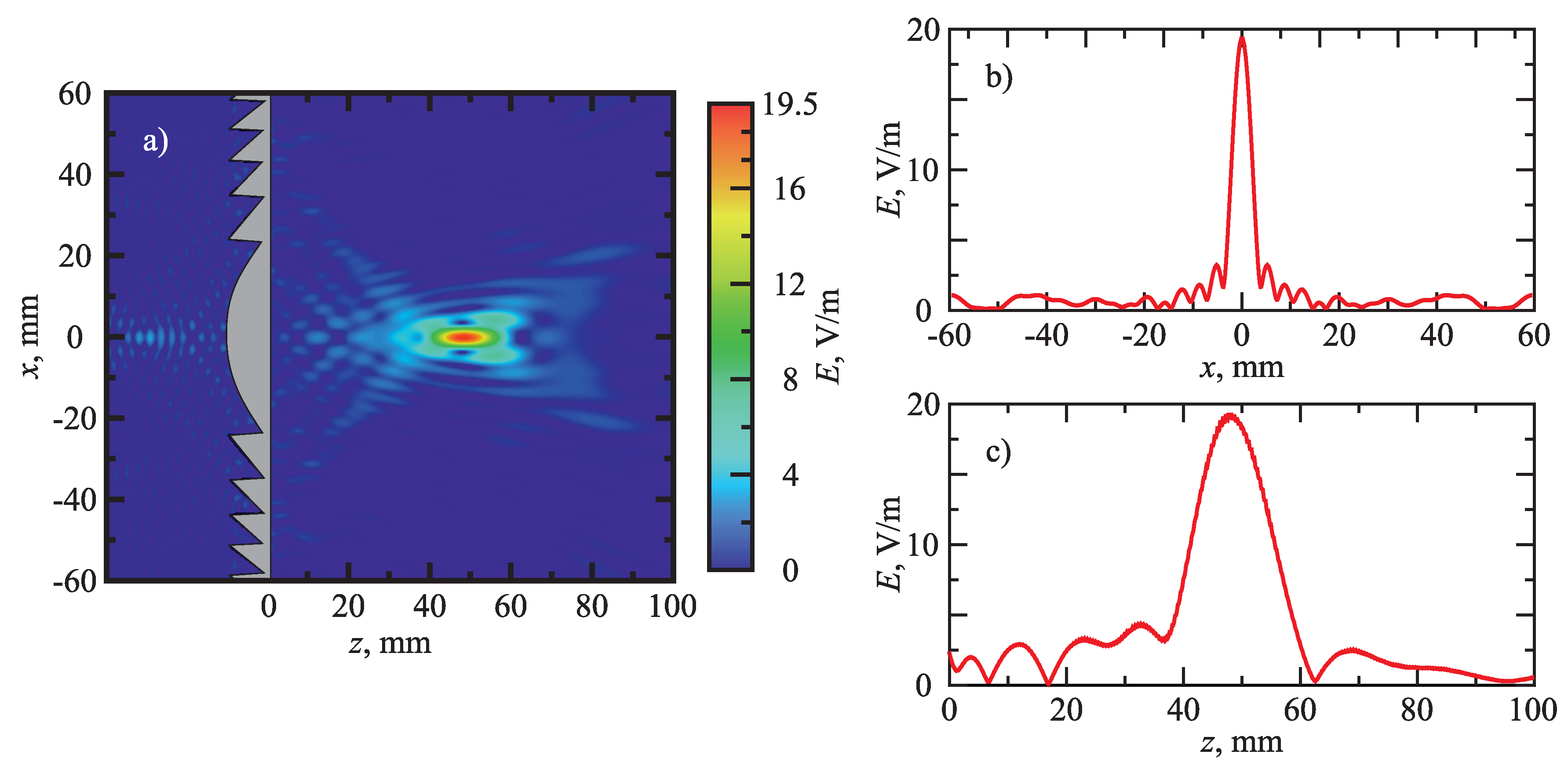
Figure 4.
Angular power distribution (in dBm) for the bare emitter or the system of emitter, enhanced with spherical or Fresnel beam-shaping solution. The insets above reveal the same distribution in mW scale and polar coordinate system. Note similar beam-shaping directivity efficiency increase, arising by enhancing the system with a beam-shaping solution (FWHM decrease by 10 times is observed). Also note a significantly larger intensity for the system, enhanced with Fresnel beam-shaping structure, compared to the spherical beam-shaping structure.
Disclaimer/Publisher’s Note: The statements, opinions and data contained in all publications are solely those of the individual author(s) and contributor(s) and not of MDPI and/or the editor(s). MDPI and/or the editor(s) disclaim responsibility for any injury to people or property resulting from any ideas, methods, instructions or products referred to in the content. |
© 2026 by the authors. Licensee MDPI, Basel, Switzerland. This article is an open access article distributed under the terms and conditions of the Creative Commons Attribution (CC BY) license (http://creativecommons.org/licenses/by/4.0/).
Copyright: This open access article is published under a Creative Commons CC BY 4.0 license, which permit the free download, distribution, and reuse, provided that the author and preprint are cited in any reuse.


