
Submitted:
06 January 2026
Posted:
06 January 2026
You are already at the latest version
Abstract
Based on the dilemma of analyzing the resonance stability of AC power grids using im-pedance models, it is demonstrated that the "negative resistance" mechanism of wide-band oscillation is untenable. A general method for describing power electronic devices using wideband voltage source converter models and wideband current source convert-er models is proposed, thereby representing the nonlinear characteristics of power elec-tronic devices with harmonic voltage sources and harmonic current sources. This allows the new energy power system to still be described by a linear system, and interprets the mechanism of wideband oscillation as a "harmonic amplification" phenomenon caused by network resonance, thus establishing a new framework for explaining the mechanism of wideband oscillation in new energy power systems. Through the analysis of two basic resonant circuits, the relationship between the damping ratio of resonant modes and the harmonic amplification factor is derived, laying a theoretical foundation for the analysis and suppression of wideband oscillation based on the s-domain nodal admittance matrix method and C-type damping filters. Based on the maximum damping criterion, a design method for C-type damping filters is proposed. The designed C-type damping filters ex-hibit strong broadband damping effects.
Keywords:
broadband oscillation
; negative resistance mechanism
; harmonic amplification mechanism
; wideband converter model
; resonance mode damping ratio
; harmonic amplification factor
; C-type damping filter
; s-domain nodal admittance matrix method
1. Introduction
As the construction of renewable energy power systems deepens, power systems increasingly exhibit power electronics characteristics at the four levels of generation, grid, load, and storage, making the previously rare broadband oscillation problems increasingly common. A large number of domestic and international literature has reported cases of broadband oscillation phenomena [1,2,3], including broadband oscillation phenomena in AC power grids [1,2] and broadband oscillation phenomena in DC power grids [3].
How can we explain the broadband constant-amplitude oscillation problems that have emerged extensively in AC power grids? The industry has proposed the following mechanism explanations [4,5,6,7]: (1) caused by improper design of power electronic device controllers; (2) caused by disruption of generalized synchronization stability; (3) caused by the "negative resistance" effect exhibited by power electronic devices; (4) caused by interactions between nonlinear devices. Among these, mechanism (3), where broadband oscillations are caused by the "negative resistance" effect of power electronic devices, is currently the most prevalent mechanism explanation in the industry, with literature on this topic being extremely abundant. This paper will demonstrate that the "negative resistance" mechanism lacks theoretical foundation and provide new mechanism explanations and suppression principles for broadband constant-amplitude oscillations.
2. Theoretical Basis of the "Negative Resistance" Mechanism
The "negative resistance" mechanism refers to the fact that certain devices in AC power grids may exhibit negative resistance effects in specific frequency bands. For example, synchronous generators exhibit negative resistance effects in sub-synchronous frequency bands [8], and two-level converters and doubly-fed induction generators exhibit negative resistance effects in certain frequency bands [9,10]. When the inherent positive resistance of the AC grid itself is insufficient to cancel out the negative resistance exhibited by certain devices in some frequency bands, and the inherent resonant frequency happens to fall within these frequency bands, the free component oscillating at the inherent resonant frequency in the voltage and current responses after disturbance will not decay, thus leading to resonance instability. The simplest examples are synchronous generators connected to a large grid through series-compensated transmission lines or doubly-fed wind farms connected to a large grid through series-compensated transmission lines.
The broadband oscillations explained by the "negative resistance" mechanism are caused by the divergence of free components in the network's physical quantities after disturbance, belonging to the category of free oscillations without excitation sources. When adopting the "negative resistance" mechanism, broadband oscillation stability is equivalent to resonance stability, and the criterion for resonance instability is the existence of resonance modes located in the right half of the complex plane [4,5,6,7].
The broadband oscillations explained by the "negative resistance" mechanism are caused by the divergence of free components in the network's physical quantities after disturbance, belonging to the category of free oscillations without excitation sources. When adopting the "negative resistance" mechanism, broadband oscillation stability is equivalent to resonance stability, and the criterion for resonance instability is the existence of resonance modes located in the right half of the complex plane [4,5,6,7].
3. Dilemma in Analyzing Resonance Stability of AC Power Grids Based on Impedance Models
Reference [4] provides reasons why resonance stability analysis and control of AC power grids based on the impedance model of power electronic devices cannot be established. The main arguments are as follows.
The impedance model belongs to the linearized model of power electronic devices. Its theoretical basis is not the local linearization method based on Taylor series expansion principles, but rather the harmonic linearization method based on harmonic balance principles. The harmonic linearization method, also called the describing function method, is an approximate description method for nonlinear devices proposed in the 1930s and developed and refined in the 1940s [11,12,13,14,15,16]. The basic principle of the harmonic linearization method is to make the mathematical model of the linearized nonlinear device satisfy a fundamental characteristic of Linear Time-Invariant (LTI) models—the frequency preservation property, that is, the property that a single-frequency excitation produces a response at the same frequency. According to this principle, the harmonic linearization method does not focus on whether the mathematical model of the linearized nonlinear device accurately describes the characteristics of the original nonlinear device. The strength of the harmonic linearization method is that it can establish a quasi-LTI model for general nonlinear devices, thus making it possible to analyze systems containing such nonlinear devices using LTI system theory. A fundamental difficulty in applying the harmonic linearization method is that the quasi-LTI model of the device established often has low accuracy, and therefore the accuracy of the stability analysis results obtained using LTI system theory based on the device's quasi-LTI model is difficult to guarantee.
The reason why the harmonic linearization method (i.e., the describing function method) has been widely applied in classical control theory is fundamentally that the describing function method discards the higher-order harmonic components in the device response. When combined with the high-frequency attenuation characteristics typically possessed by practical engineering systems, the describing function method becomes an effective linearization method for nonlinear devices. However, for power system resonance stability analysis, the harmonic linearization method establishes an incremental linearization model of the device at the AC steady-state operating point, using the dual-input describing function method. The derived incremental impedance model is an approximate model with relatively low accuracy, which the author refers to as the LTI impedance model. When deriving the LTI impedance model of a device based on the dual-input describing function method, what is discarded is not entirely the higher-order harmonic components in the device response. Therefore, even if the actual system has high-frequency attenuation characteristics, the reliability of the analysis results based on the LTI impedance model cannot be guaranteed.
To overcome the shortcoming of low accuracy in the LTI impedance model obtained based on the dual-input describing function method, the industry has proposed a method of using frequency-coupled impedance models to replace LTI impedance models for power system resonance stability analysis. Furthermore, frequency-coupled impedance modeling has become a major research hotspot in recent years. However, although the frequency-coupled impedance model has indeed achieved improvements in the accuracy of describing device characteristics, the frequency-coupled impedance model is not an LTI model, as it does not possess the fundamental characteristic of LTI models where a single-frequency excitation produces a response at the same frequency. Therefore, connecting the frequency-coupled impedance model of power electronic devices with the LTI models of other components and applying LTI system theory to analyze the stability of the entire system is theoretically and logically untenable.
Thus, the current impedance-model-based analysis of AC power grid resonance stability faces a dilemma, namely the "cutting the feet to fit the shoes" predicament and the "walking into a dead-end path" predicament.
The so-called "cutting the feet to fit the shoes" predicament refers to the fact that in order to satisfy the frequency preservation characteristic of LTI models, that is, the characteristic that a single-frequency excitation produces a response at the same frequency, the LTI model of power electronic devices needs to be derived with the aid of the dual-input describing function method. In the process of deriving the LTI model of power electronic devices based on the dual-input describing function method, non-higher-order harmonic components in the incremental response of power electronic devices are inevitably discarded. Because the discarded non-higher-order harmonic components are not a higher-order small quantity compared to the fundamental component of the incremental response, they cause substantial damage to the accuracy of the derived LTI model of power electronic devices. This process can be very aptly described by the Chinese idiom "cutting the feet to fit the shoes." Here, "cutting the feet" refers to discarding the non-higher-order harmonic components in the incremental response of power electronic devices, thereby causing substantial damage to the accuracy of the derived LTI model; and the so-called "to fit the shoes" refers to satisfying the frequency preservation characteristic of LTI models so that the well-established LTI system analysis theory can be applied for analysis. Since the derived LTI model of power electronic devices has undergone "feet cutting," its description of the power electronic device response is incomplete, and therefore the results of analyzing power system resonance stability based on this model using LTI system theory are unreliable.
The so-called "walking into a dead-end path" predicament refers to the fact that although a frequency-coupled impedance (or admittance) model of power electronic devices with relatively high accuracy can be derived, the frequency-coupled impedance (or admittance) model is not an LTI model, and therefore the frequency-coupled impedance model cannot be connected with the LTI models of other components to apply LTI system theory to analyze the stability of the entire system. Based on the frequency-coupled impedance (or admittance) model, there are currently no available mathematical tools to further analyze the resonance stability of the entire system, meaning that after deriving the frequency-coupled impedance (or admittance) model, there is no path forward. From a more macro perspective, if there existed a theory that could analyze AC power grid resonance stability through frequency-coupled impedance models, it would mean that the general nonlinear system stability analysis problem that has troubled humanity for hundreds of years has been solved; because for any nonlinear device, deriving its frequency-coupled impedance model is relatively straightforward. The author uses the Chinese saying "walking into a dead-end path" to describe the practice of attempting to conduct AC power grid resonance stability analysis using frequency-coupled impedance models, which aptly describes the predicament of this approach.
Since the AC power grid resonance stability analysis based on the incremental small-signal impedance model of power electronic devices is theoretically untenable, the "negative resistance" mechanism developed on this basis to explain broadband oscillations is also theoretically untenable; similarly, the "impedance reshaping" control method developed on this basis to suppress broadband oscillations is also theoretically untenable.
4. A New Framework for Analyzing the Mechanism of Wideband Oscillation in New Energy Power Systems
The previous section has explained the reasons why the incremental small-signal impedance model of power electronic devices is not applicable to AC power grid resonance stability analysis, thereby negating the "negative resistance" mechanism for explaining broadband oscillations. So how should the broadband oscillation problems in renewable energy power systems be analyzed?
First, the approach of describing power electronic devices according to nonlinear models encounters difficulties when analyzing resonance stability. This is mainly manifested in two aspects: First, for general nonlinear models, there is no universally applicable method to analyze their stability. Second, renewable energy power systems contain a massive number of power electronic devices; currently, there is no universally applicable method for stability analysis of a single power electronic device, let alone analyzing systems containing massive numbers of power electronic devices.
Macroscopically, all power electronic devices can be divided into voltage source converters or current source converters. For voltage source converters, a broadband voltage source converter model can be used to describe them. The general structure of the broadband voltage source converter model is shown in Figure 1. In Figure 1, the instantaneous value expression of the fundamental voltage source is U1mcos(ω0t+ϕ1), where U1m is the fundamental voltage source amplitude, ω0 is the fundamental voltage source angular frequency, ϕ1 is the fundamental voltage source initial phase angle, and the corresponding phasor expression is U1m∠ϕ1; the instantaneous value expression of the h-th harmonic voltage source is Uhmcos(hω0t+ϕh), where Uhm is the harmonic voltage source amplitude, ϕh is the harmonic voltage source initial phase angle, and the corresponding phasor expression is Uhm∠ϕh. It is particularly important to note that the harmonic order h of the harmonic voltage source in Figure 1 is not necessarily a positive integer. This is because for converters such as MMC, the submodule capacitor voltage balancing control is often implemented using some sorting algorithm, which results in the synthesized internal electromotive force not being a strictly periodic waveform, and the harmonic orders it contains are not necessarily positive integers. Therefore, the harmonic order h in the harmonic voltage source model can be understood as a continuous variable greater than 1. In Figure 1, Llink and Rlink are the internal inductance and internal resistance of the voltage source converter, which are related to the interface transformer, interface reactor, arm reactor, etc., and depend on different voltage source converter types, but these two parameters are generally considered to be constant parameters.
For current source converters, a broadband current source converter model can be used to describe them. The general structure of the broadband current source converter model is shown in Figure 2. In Figure 2, the instantaneous value expression of the fundamental current source is I1mcos(ω0t+φ1), where I1m is the fundamental current source amplitude, ω0 is the fundamental current source angular frequency, φ1 is the fundamental current source initial phase angle, and the corresponding phasor expression is I1m∠φ1; the instantaneous value expression of the h-th harmonic current source is Ihmcos(hω0t+φh), where Ihm is the harmonic current source amplitude, φh is the harmonic current source initial phase angle, and the corresponding phasor expression is Ihm∠φh. It should also be noted that the harmonic order h of the harmonic current source in Figure 2 is not necessarily a positive integer; h can be understood as a continuous variable greater than 1. In Figure 2, Lsh and Rsh are the internal inductance and internal resistance of the current source converter, which are related to the specific structure and parameters of the current source converter, but these two parameters are generally considered to be constant parameters.
If the broadband voltage source converter model and the broadband current source converter model are used to describe all power electronic devices in renewable energy power systems, the nonlinear characteristics of power electronic devices can be represented by harmonic voltage sources or harmonic current sources. Moreover, the series inductance and series resistance in the broadband voltage source converter model, as well as the parallel inductance and parallel resistance in the broadband current source converter model, are all linear elements. Therefore, after adding the broadband voltage source converter model and the broadband current source converter model to the power grid, the entire network remains a linear network, and thus the powerful s-domain nodal admittance matrix method [4,5,6,7] can be used to complete the resonance stability analysis of large-scale power systems.
Since power electronic devices typically eliminate zero-sequence components flowing into the power grid through transformer connections or control methods, only positive-sequence harmonic components and negative-sequence harmonic components in the power grid need to be considered in broadband oscillation stability analysis. Moreover, since the positive-sequence circuit model and negative-sequence circuit model in static components are the same, the positive-sequence network model can be used to uniformly analyze the harmonic components of all orders in power electronic devices.
Since there are no negative resistance elements in the broadband voltage source converter model and the broadband current source converter model, it is impossible for broadband voltage source converters and broadband current source converters to cause resonance instability problems. However, when the frequency of the harmonic voltage or harmonic current generated by power electronic devices happens to be close to a certain resonance frequency in the network, it may cause the harmonic voltage or harmonic current at that frequency to be amplified in a certain area of the power grid, thereby producing sustained constant-amplitude oscillations, that is, broadband oscillation phenomena. This explains the mechanism of broadband oscillations as "harmonic amplification" caused by network resonance, thus establishing a new framework for analyzing the mechanism of broadband oscillations in renewable energy power systems.
Compared with the "negative resistance" mechanism, the new framework interprets the broadband oscillation mechanism as "harmonic amplification" caused by network resonance. The main difference between the two lies in the different nature of the oscillations. The broadband oscillations corresponding to the "negative resistance" mechanism belong to the divergent oscillations of free components in network physical quantities, while the broadband oscillations corresponding to the "harmonic amplification" mechanism belong to the amplification of forced components in network physical quantities. Both are related to network resonance modes, but the resonance modes obtained based on the "negative resistance" mechanism may be located in the right half of the complex plane; whereas the resonance modes obtained based on the "harmonic amplification" mechanism are all located in the left half of the complex plane. This raises the question of how to determine whether "harmonic amplification" will occur based on the resonance mode information located in the left half of the complex plane.
5. Analysis of the Relationship Between Network Resonance Modes and Harmonic Amplification
As mentioned previously, based on the s-domain nodal admittance matrix method [4,5,6,7], it is easy to calculate all resonance modes of large-scale power networks in the frequency band of interest, and further obtain the nodal voltage mode shapes and participation factors of each resonance mode, as well as the sensitivity of specific resonance mode damping to specific component parameters. The current question is how to quantitatively analyze the degree of harmonic amplification based on resonance mode information. In the following, the most basic RLC series resonant circuit and RLC parallel resonant circuit are taken as research objects to examine the relationship between resonance modes and harmonic amplification.
5.1. Relationship Between Resonance Modes and Harmonic Amplification in RLC Series Resonant Circuits
The simple system of a harmonic voltage source exciting an RLC series resonant circuit under consideration is shown in Figure 3. In Figure 3, the instantaneous value expression of the h-th harmonic voltage source is Uhmcos(hω0t+ϕh), where Uhm is the harmonic voltage source amplitude, ω0 is the fundamental angular frequency, ϕh is the harmonic voltage source initial phase angle, and note that the harmonic order h is a continuous variable greater than 1; the phasor expression corresponding to the h-th harmonic voltage source is Uhm∠ϕh; R, L, C are the resistance, inductance, and capacitance of the series resonant circuit, respectively; Iseries is the h-th harmonic current phasor flowing through the series resonant circuit.
The s-domain nodal admittance matrix method is used to find the resonance modes of the system in Figure 3. The system in Figure 3 can be regarded as a single-node system, and the expression of the s-domain nodal admittance matrix Y(s) is
Therefore, the characteristic equation of the system is
Rearranging equation (2), the system characteristic equation is
Comparing equation (3) with the standard form of the second-order system characteristic equation (4),
the undamped resonant angular frequency ωn and damping ratio ζ are obtained as
The quality factor Q is defined in the RLC series circuit as
Thus, the damping ratio of the RLC series resonant circuit is obtained as
The harmonic amplification characteristics of Figure 3 are analyzed below. When the R and C components in the RLC series resonant circuit are removed, leaving only the inductance L, the circuit will not exhibit harmonic amplification. Let the current flowing through the loop when only the inductance L is retained in the RLC series resonant circuit at the undamped resonant angular frequency ωn be the reference current Ibase, then the expression for the reference current is
while the current flowing through the RLC series resonant circuit at the undamped resonant angular frequency ωn is
Thus, the harmonic current amplification factor KI can be defined as
Equations (10) and (7) establish the relationship between the harmonic current amplification factor KI and the resonance mode damping ratio ζ through the quality factor Q, as
If the RLC series resonant circuit is required not to exhibit harmonic current amplification, then KI ≤ 1 is required, i.e., ζ ≥ 1/2; if KI ≤ 2 is required, then ζ ≥ 1/4 is required; if KI ≤ 10 is required, then ζ ≥ 1/20 = 5% is required. This result shows that when ζ is greater than 5%, the harmonic amplification factor can be ensured to be less than 10.
5.2. Relationship Between Resonance Modes and Harmonic Amplification in RLC Parallel Resonant Circuits
The simple system of a harmonic current source exciting an RLC parallel resonant circuit under consideration is shown in Figure 4. In Figure 4, the instantaneous value expression of the h-th harmonic current source is Ihmcos(hω0t+φh), where Ihm is the harmonic current source amplitude, ω0 is the fundamental angular frequency, φh is the harmonic current source initial phase angle, and note that the harmonic order h is a continuous variable greater than 1; the phasor expression corresponding to the h-th harmonic current source is Ihm∠φh; R, L, C are the resistance, inductance, and capacitance of the parallel resonant circuit, respectively; Uparallel is the h-th harmonic voltage phasor of the RLC parallel resonant circuit.
The s-domain nodal admittance matrix method is used to find the resonance modes of the system in Figure 4. The system in Figure 4 is a single-node system, and the expression of the s-domain nodal admittance matrix Y(s) is
Therefore, the characteristic equation of the system is
Rearranging equation (13), the system characteristic equation is
Comparing equation (14) with the standard form of the second-order system characteristic equation (4), the undamped resonant angular frequency ωn and damping ratio ζ are obtained as
For the RLC parallel circuit, the definition of its quality factor has an inverse relationship with the quality factor of the RLC series circuit. The quality factor q of the RLC parallel circuit is defined as
Thus, the damping ratio ζ of the RLC parallel resonant circuit is obtained as
The harmonic amplification characteristics of Figure 4 are analyzed below. When the R and C components in the RLC parallel resonant circuit are removed, leaving only the inductance L, the circuit will not exhibit harmonic amplification. Let the voltage across L when only the inductance L is retained in the RLC parallel resonant circuit at the undamped resonant angular frequency ωn be the reference voltage Ubase, then the expression for the reference voltage is
while the voltage across the RLC parallel resonant circuit at the undamped resonant angular frequency ωn is
Thus, the harmonic voltage amplification factor KV can be defined as
Equations (20) and (17) establish the relationship between the harmonic voltage amplification factor KV and the resonance mode damping ratio ζ through the quality factor q, as
If the RLC parallel resonant circuit is required not to exhibit harmonic voltage amplification, then KV≤1 is required, i.e., ζ≥1/2; if KV≤2 is required, then ζ≥1/4 is required; if KV≤10 is required, then ζ≥1/20=5% is required. This result shows that when ζ is greater than 5%, the harmonic amplification factor can be ensured to be less than 10.
5.3. Summary of the Relationship Between Network Resonance Modes and Harmonic Amplification
According to the examination of the most basic RLC series resonant circuit and RLC parallel resonant circuit in the previous two sections, there is a definite relationship between the resonance mode damping ratio ζ and the harmonic amplification factor K: the larger the damping ratio ζ, the smaller the harmonic amplification factor K. Although this result is derived for the two most basic types of resonant circuits, in engineering applications, it may be assumed that the above result still holds, i.e., the relationship between the harmonic amplification factor K and the resonance mode damping ratio ζ is K=1/(2ζ).
6. Harmonic Amplification Suppression Method Based on C-Type Damping Filter
As mentioned previously, there is an inverse relationship between the harmonic amplification factor K and the resonance mode damping ratio ζ. To reduce the harmonic amplification factor K, it is necessary to increase the resonance mode damping ratio ζ. If a parallel device is used to increase the resonance mode damping ratio ζ, then according to Figure 4, the purpose can be achieved simply by connecting a resistive element in parallel, and the smaller the resistance value of the parallel resistive element, the better. However, the method of using parallel resistance to increase the resonance mode damping ratio ζ inevitably leads to a large amount of power loss in the resistive element at the fundamental frequency, and the smaller the resistance value, the greater the loss. Therefore, the following question arises: is there such a device that presents high impedance at the fundamental frequency and does not consume fundamental frequency power, while presenting resistive characteristics in a specified frequency band, thereby increasing the resonance mode damping ratio in the specified frequency band? The answer is yes. Among passive devices, the C-type damping filter is the device that most closely meets the above requirements [17,18].
6.1. Structure and Basic Principles of C-Type Damping Filter
The structure of the C-type damping filter is shown in Figure 5. At the fundamental frequency, the C-type damping filter satisfies the condition XL1=XC1, and the fundamental frequency voltage drops across the inductor L1 and capacitor C1 completely cancel out, resulting in zero fundamental frequency voltage across the resistor R and zero fundamental frequency power consumption. Considering that the reactive power output of the C-type damping filter at the fundamental frequency is entirely determined by the capacitor C, while the capacitor C1 has no effect on the reactive power output at the fundamental frequency, it is desirable to have the capacitor C1 as small as possible to minimize investment costs. However, the next section will demonstrate that the capacitor C1 has an approximately quadratic relationship with the tuning frequency of the C-type damping filter. The higher the tuning frequency of the C-type damping filter, the larger the capacitor C1. Therefore, C-type damping filters are generally tuned at lower frequencies. Traditionally, C-type damping filters have only been used as low-order harmonic filters, for example, as third harmonic filters. When using C-type damping filters to suppress harmonic amplification, the tuning frequency of the C-type damping filter can be selected at the third harmonic or lower frequencies according to the requirements of the resonance mode damping ratio ζ in the specified frequency band.
Compared with single-tuned filters, the advantages of C-type damping filters are mainly manifested in two aspects. The first aspect is low fundamental frequency loss. When single-tuned filters are used as low-order harmonic filters, the distance between their tuning frequency and the fundamental frequency is very small, causing the impedance of the single-tuned filter at the fundamental frequency to remain at a low value, thereby causing large power losses. The second aspect is the impedance characteristics in the high-frequency range. C-type damping filters exhibit resistive-inductive characteristics in the high-frequency range, and the resistance value remains basically constant, providing substantial damping. Single-tuned filters, on the other hand, are inductive in the high-frequency range with large reactance values and do not provide damping. Due to the above advantages, C-type damping filters have been widely used in HVDC transmission projects, for example, the Sellindge station of the English Channel HVDC project, as well as the Longquan station of the Longquan-Zhengping HVDC project and the Deyang station of the Deyang-Baoji HVDC project all use C-type damping filters [17,18,19,20] to eliminate the risk of third harmonic resonance that may occur between converter stations and the power grid.
6.2. Parameter Design Method for C-Type Damping Filter
Although the C-type damping filter was proposed in 1982 and applied at the Sellindge station of the English Channel HVDC project [17,18,19], and numerous subsequent publications have discussed the parameter design of C-type damping filters [21,22,23,24,25,26], the overall design process is not sufficiently concise and involves a trial-and-error process. Based on the maximum damping criterion, this paper proposes a one-step C-type damping filter design method, with the derivation process as follows.
Referring to the C-type damping filter structure shown in Figure 5, let the fundamental reactive power allocated to the C-type damping filter be Qf, and let the fundamental reactance of capacitor C be XC=1/(ω0C), the fundamental reactance of capacitor C1 be XC1=1/(ω0C1), and the fundamental reactance of inductor L1 be XL1= ω0L1, where ω0 is the fundamental angular frequency of the power system. According to the properties of the C-type damping filter, the L1-C1 circuit is in series resonance at the fundamental frequency, thus
In equation (22), U1 is the fundamental effective value of the system line-to-line voltage at the C-type damping filter connection point. The impedance expression of the C-type damping filter at the h-th harmonic is
Let the C-type damping filter be tuned to harmonic order n, then at the tuning frequency point the impedance of the C-type damping filter is purely resistive, i.e., Im[Z(n)]=0, therefore
Rearranging equation (24) into a quadratic equation in terms of XC1 gives
For equation (25) to have a solution, it must satisfy
Solving the above inequality yields
According to the structure of the C-type damping filter, under the same harmonic voltage, the smaller R is, the greater the damping power consumed by R, and the better the damping effect of the C-type damping filter. Therefore, let R take the minimum value in equation (27), which is referred to as the maximum damping criterion in this paper. This yields
At this point, equation (25) has a unique solution, which is
Thus, the impedance of the C-type damping filter at the tuning frequency is
According to equation (23), the impedance of the C-type damping filter at the fundamental frequency is
Similarly, according to equation (23), the impedance of the C-type damping filter at infinite frequency is
6.3. Impedance-Frequency Characteristic Display of C-Type Damping Filter
Let the fundamental reactive power Qf of the C-type damping filter be 200 Mvar for the high scheme, 150 Mvar for the medium scheme, and 100 Mvar for the low scheme. The rated frequency of the AC system is 50 Hz, the fundamental voltage of the AC bus is 505 kV, and the filter is tuned at the third harmonic frequency. Find the parameters of the C-type damping filter and plot its impedance-frequency characteristics.
First, solve for the parameters of the C-type damping filter under the three schemes. According to equations (22), (28), and (29), the parameters of the C-type damping filter under the three schemes are shown in Table 1.
As can be seen from Table 1, for a C-type damping filter tuned to the third harmonic, the value of C1 is 4 times that of the reactive power compensation capacitor C; the larger the fundamental capacity of the filter, the larger the values of capacitor C and capacitor C1, and the smaller the value of inductor L1.
A comparison of the impedance-frequency characteristics of the C-type damping filter under the three schemes is shown in Figure 6.
As can be seen from Figure 6, the C-type damping filter has the following characteristics: (1) The complex impedance value of the C-type damping filter at the tuning frequency point is equal to half the resistance value of the resistive element; (2) The minimum impedance value of the C-type damping filter occurs between the fundamental frequency and the tuning frequency point, and the minimum impedance value is less than half the resistance value of the resistive element; (3) Regardless of the fundamental capacity value, the characteristic of the impedance angle of the C-type damping filter varying with frequency remains unchanged; (4) After the tuning frequency point, the impedance angle of the C-type damping filter is greater than zero but close to zero, exhibiting slightly inductive and resistive characteristics; (5) The complex impedance value of the C-type damping filter is approximately equal to the resistance value R of the resistive element over a wide frequency range, therefore the C-type damping filter has a strong broadband damping effect; (6) The larger the fundamental capacity of the C-type damping filter, the smaller the resistance value in the broadband range, and the stronger the damping effect.
7. Conclusions
This paper conducts research on the mechanism of broadband oscillations and their suppression techniques, negates the "negative resistance" mechanism of broadband oscillations, and proposes the "harmonic amplification" mechanism of broadband oscillations. The main conclusions are as follows:
(1) When using the incremental small-signal impedance model of power electronic devices derived based on the dual-input describing function method to analyze the resonance stability of AC power grids, it is impossible to escape the "cutting the feet to fit the shoes" predicament and the "walking into a dead-end path" predicament. Therefore, the "negative resistance" mechanism for explaining broadband oscillations and the "impedance reshaping" control method for suppressing broadband oscillations developed on this basis are theoretically untenable.
(2) When using the broadband voltage source converter model and the broadband current source converter model to describe power electronic devices, the nonlinear characteristics of power electronic devices can be represented by harmonic voltage sources or harmonic current sources, thus allowing the use of linear circuit theory to analyze the broadband oscillation problems in renewable energy power systems.
(3) Based on the broadband voltage source converter model or broadband current source converter model of power electronic devices, the mechanism of broadband oscillations can be explained as the "harmonic amplification" phenomenon caused by network resonance, thus establishing a new framework for analyzing the mechanism of broadband oscillations in renewable energy power systems.
(4) In the context of renewable energy power systems, harmonic frequencies are no longer discrete quantities but can be considered continuous quantities.
(5) Based on the "harmonic amplification" mechanism of broadband oscillations, the powerful s-domain nodal admittance matrix method can be used to calculate all resonance modes of the positive-sequence network, and there is a definite inverse relationship between the resonance mode damping ratio and the harmonic amplification factor.
(6) The method of designing C-type damping filters based on the maximum damping criterion is simple and clear; the complex impedance value of the designed C-type damping filter at the tuning frequency point is equal to half the resistance value of the resistive element; in the broadband above the tuning frequency point, the impedance angle of the C-type damping filter is greater than zero but close to zero, exhibiting slightly inductive and resistive characteristics; the complex impedance value of the C-type damping filter in the broadband above the tuning frequency point is approximately equal to the resistance value R of the resistive element; the larger the fundamental capacity of the C-type damping filter, the smaller the resistance value in the broadband range, and the stronger the damping effect.
Funding
This research was supported by the Joint Funds of the National Natural Science Foundation of China and China Southern Power Grid Company Limited, grant number U24B2076.
Data Availability Statement
The data presented in this study are available on request from the corresponding author. The data are not publicly available due to privacy reasons.
Conflicts of Interest
The author declares no conflict of interest. The funders had no role in the design of the study; in the collection, analyses, or interpretation of data; in the writing of the manuscript; or in the decision to publish the results.
References
- LI Mingjie, YU Zhao, XU Tao, HE Jingbo, WANG Chao, XIE Xiaorong, LIU Chun. Study of Complex Oscillation Caused by Renewable Energy Integration and Its Solution. Power System Technology, 2017, 41(4): 1035-1042.
- LÜ Jing, DONG Peng, SHI Gang, CAI Xu, LI Xiaolin. Subsynchronous Oscillation and Its Mitigation of MMC-Based HVDC With Large Doubly-Fed Induction Generator-Based Wind Farm Integration. Proceedings of the CSEE, 2015, 35(19): 4852-4860.
- LI Yunfeng, TANG Guangfu, HE Zhiyuan, AN Ting, YANG Jie, WU Yanan, KONG Ming. Damping Control Strategy Research for MMC Based HVDC System. Proceedings of the CSEE, 2016, 36(20): 5492-5503.
- XU Zheng, XIAO Huangqing, ZHANG Zheren. Flexible power transmission systems based on cascaded submodule converters. Singapore: Springer Nature, 2026.
- XU Zheng, WANG Shijia, XIN Facai, XIAO Huangqing. Qualitative analysis method of electric network resonance stability. Electric Power Construction,2017,38(11):1-8.
- Xu, Z. Three Technical Challenges Faced by Power Systems in Transition. Energies 2022, 15, 4473. [CrossRef]
- XU Zheng. Resonance stability analysis method based on s-domain node admittance matrix. Electric Power Automation Equipment,2023,43(10):1-8.
- ANDERSON P M, AGRAWAL B L, VAN NESS J E. Subsynchronous Resonance in Power Systems. New York: IEEE Press, 1990.
- XIN Facai, XU Zheng. Research on characteristic Indices for negative resistive and capacitive effect of two-level voltage-source converter. Automation of Electric Power Systems,2021,45(13):12-19.
- XING Facai,XU Zheng. Investigation on Negative-Resistance Effect of Doubly-fed Induction Generator. Acta Energiae Solaris Sinica, 2022,43(4):324-332.
- XIANG Guobo. Harmonic Linearization Principle in Nonlinear Automatic Control Systems. Information and Control,1980,9(1):41-51.
- WEST John C. Analytical techniques for non-linear control systems. The English University Press Ltd., 1960.
- ZHU S J. Approximate analysis methods for nonlinear systems. Beijing: National Defense Industry Press, 1980.
- XIANG G B. Nonlinear systems[M]. Beijing: Knowledge Press, 1991.
- SLOTINE J J E, LI Weiping. Applied nonlinear control. New Jersey:Prentice-Hall, Inc.,1991.
- GASPARYAN O N. Linear and nonlinear multivariable feedback control: a classical approach. West Sussex:John Wiley & Sons,2008.
- Abramovich B J , Brewer G L , Welch I M . Harmonic filters for the Sellindge converter station. GEC Journal of Science and Technology,1982,48 (1):35-38.
- Arrillaga J, Bradley D A, Bodger D S. Power system harmonics. New Jersey: John Wiley & Sons,1985.
- Das J C. Power system harmonics and passive filter designs. New Jersey: John Wiley & Sons,2015.
- HU Yuyang, YU Shanshan. Reason analysis of HP3 filter differential protection action in Deyang converter station. Central China Electric Power,2011,24(1):64-67.
- TIAN Wei, JIAN Zhiqing. The engendering and harnessing for the harmonics from non-ferrous-metal machining factories. Northeast Electric Power Technology, 1999,20(7):48-51.
- WENG Limin, ZHANG Guangxiang, JIN Jianfeng, ZHANG Qichun. Research on the characteristics of two new types of filters. Power Capacitors, 2000,29(3):39-43.
- YOU Zhongquan. Characteristics and calculation of C-Type filter for DC arc furnace at Daye steel plant. Distribution & Utilization, 2001, 18(6):42-44.
- YOU Zhongquan. Control characteristics of arc stabilizing device of DC electric arc furnace and characters analysis of C-type filter. Metallurgical Power, 2001, (4):1-3.
- TAO Qian, LIU Kaipei. Application and optimization of C-type filter in hybrid active power filter. Electric Power Automation Equipment, 2009, 29(2):39-43.
- WANG Li, LIU Chanbin. C-type filter used for harmonic control in power rectifier plant. China Chlor-Alkali. 2018, (5):1-3.
Figure 1.
Wideband voltage source converter model.
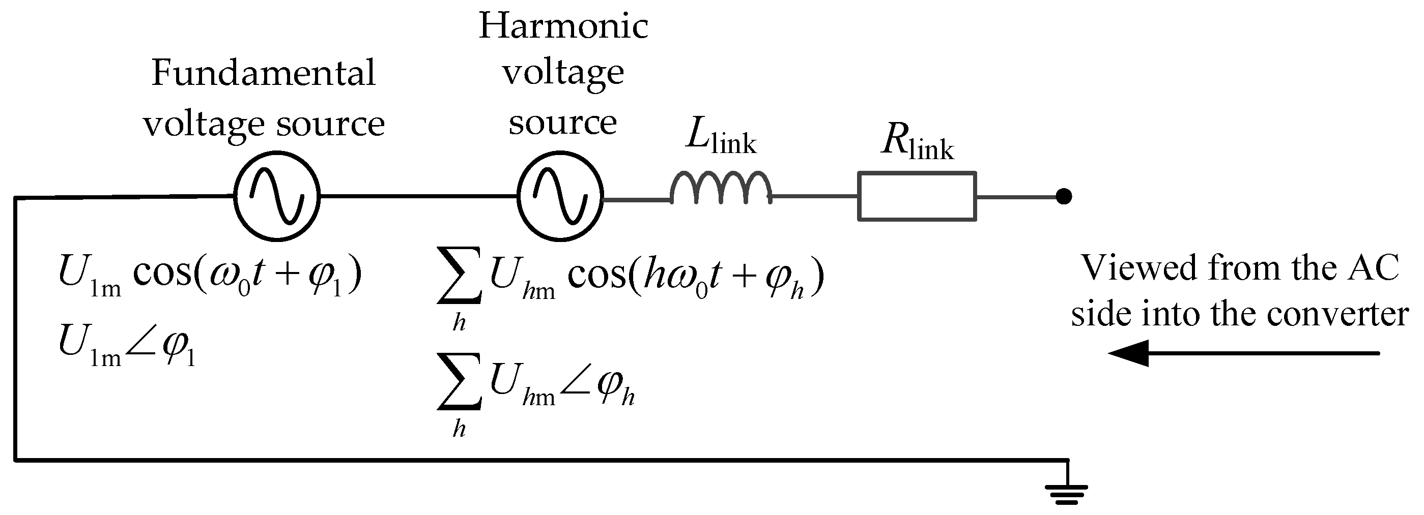
Figure 2.
Wideband current source converter model.
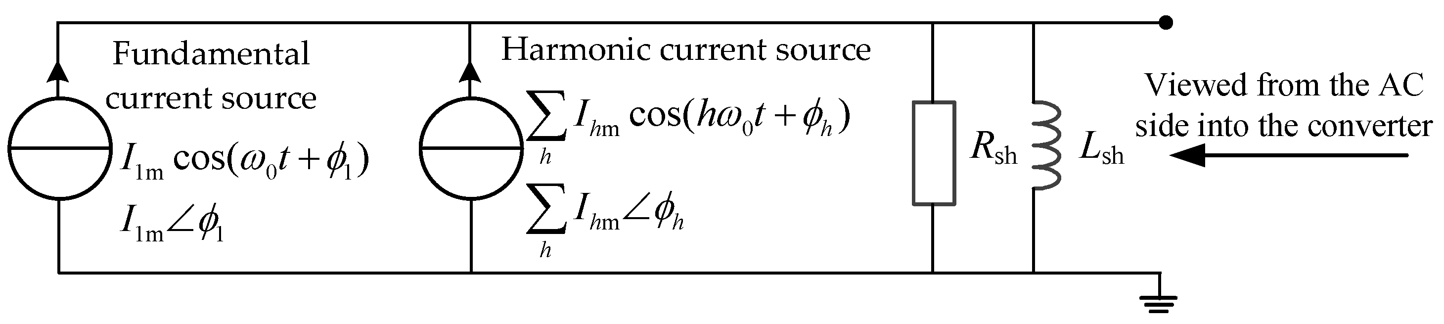
Figure 3.
The RLC series resonant circuit
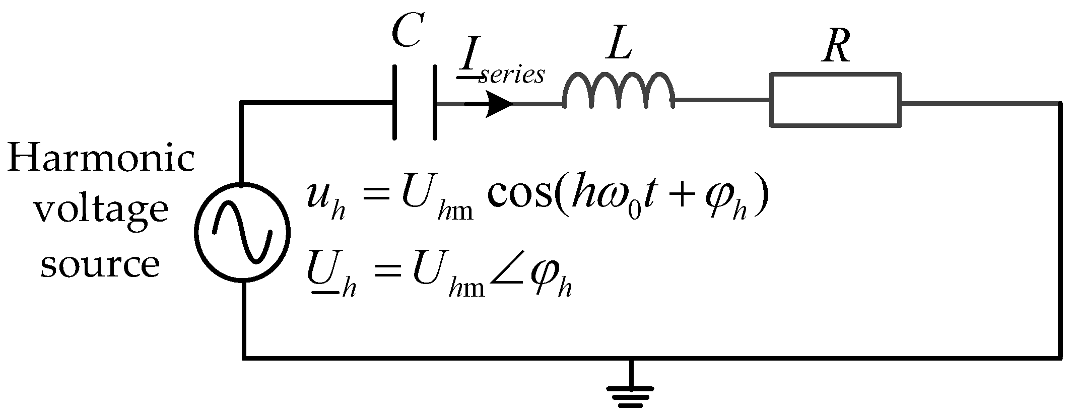
Figure 4.
The RLC parallel resonant circuit

Figure 5.
Structure of C-type damping filter.
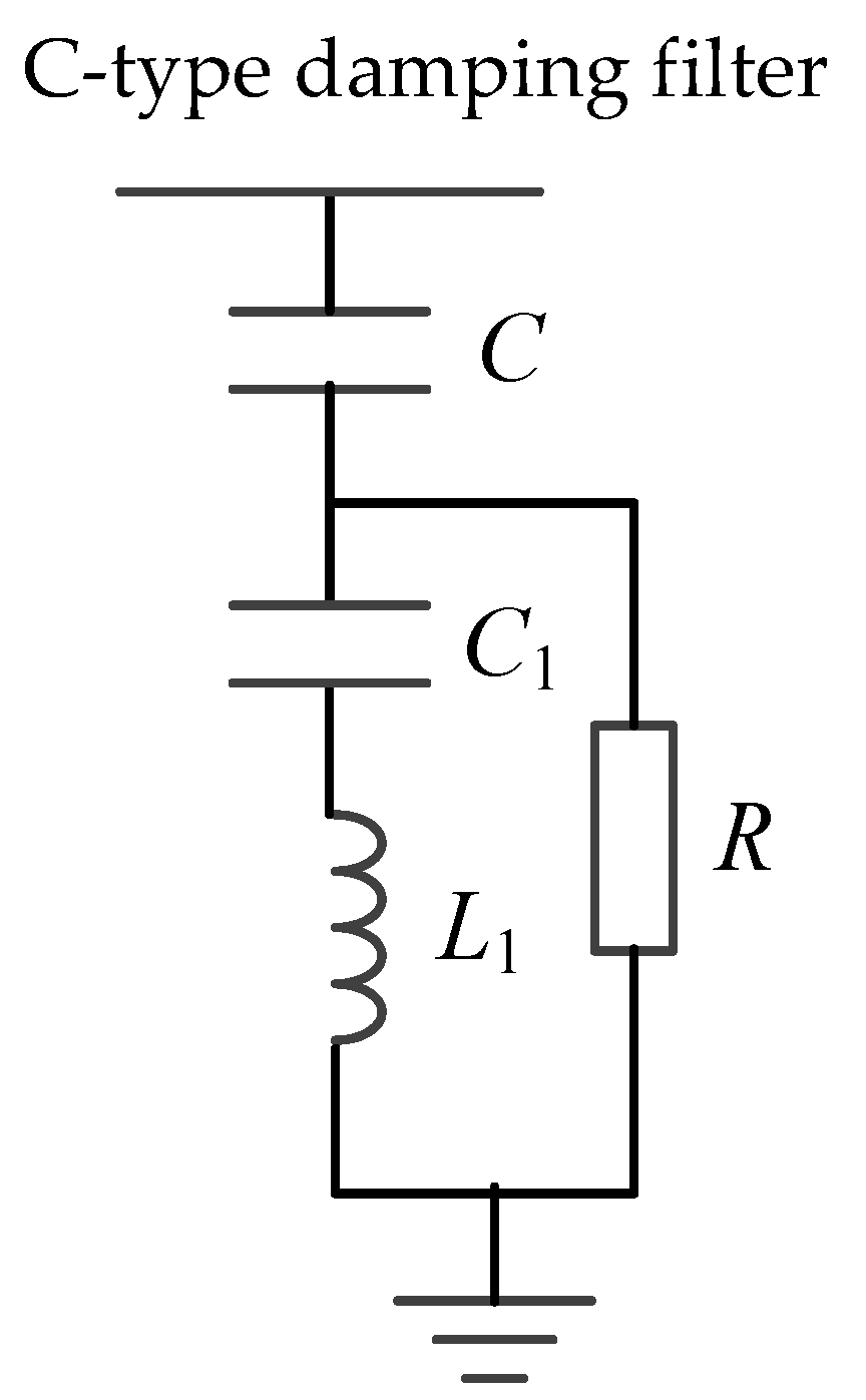
Figure 6.
Comparison of impedance characteristics of C-type damped filters with different capacities: (a) Impedance magnitude-frequency characteristics; (b) Impedance angle-frequency characteristics.
Figure 6.
Comparison of impedance characteristics of C-type damped filters with different capacities: (a) Impedance magnitude-frequency characteristics; (b) Impedance angle-frequency characteristics.
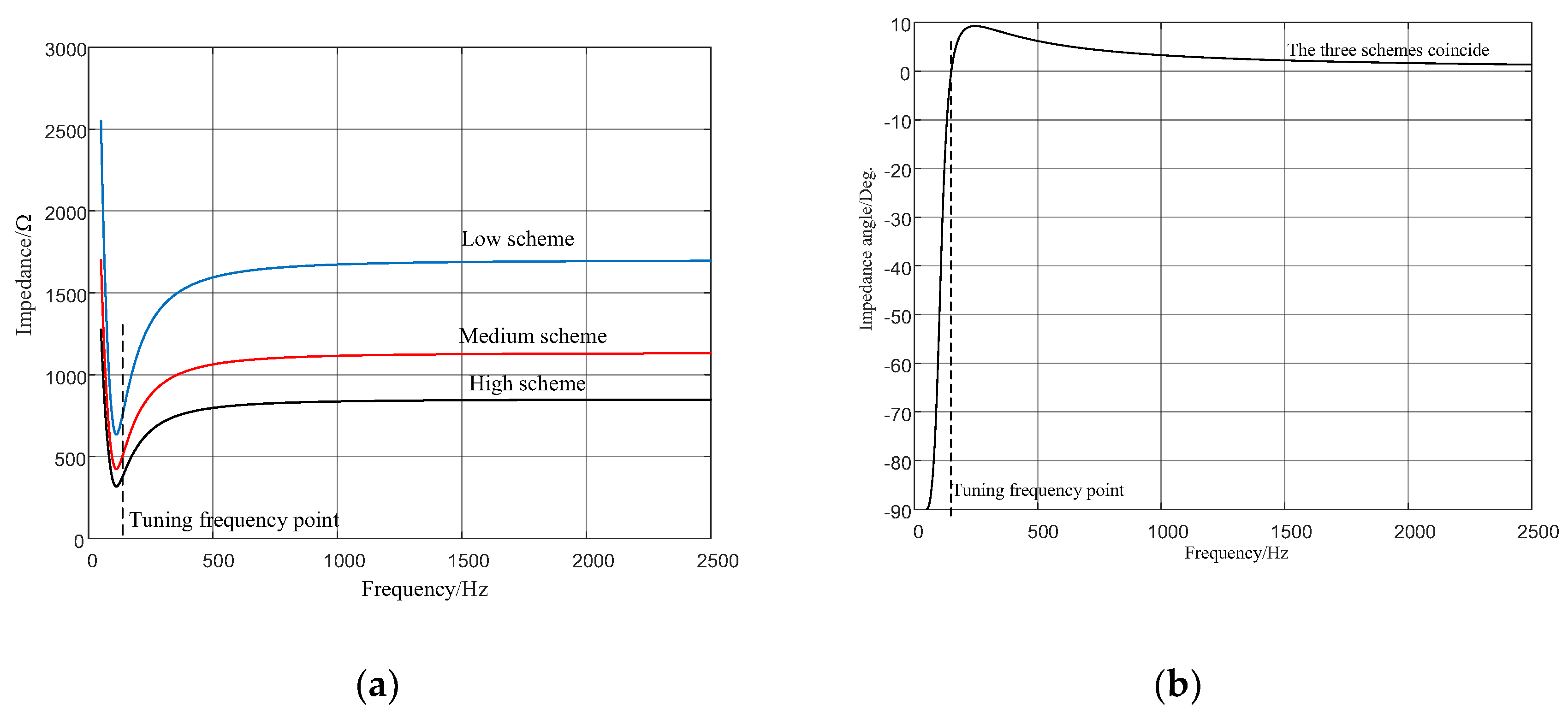

Table 1.
C-Type Damping Filter Parameters for Three Schemes.
| fundamental reactive power /Mvar | C/μF | C1/μF | L1/H | R/Ω |
| high scheme 200 | 2.4963 | 9.9852 | 1.0147 | 850.0833 |
| medium scheme 150 | 1.8722 | 7.4889 | 1.3529 | 1133.4 |
| low scheme 100 | 1.2482 | 4.9926 | 2.0294 | 1700.2 |
Disclaimer/Publisher’s Note: The statements, opinions and data contained in all publications are solely those of the individual author(s) and contributor(s) and not of MDPI and/or the editor(s). MDPI and/or the editor(s) disclaim responsibility for any injury to people or property resulting from any ideas, methods, instructions or products referred to in the content. |
© 2026 by the authors. Licensee MDPI, Basel, Switzerland. This article is an open access article distributed under the terms and conditions of the Creative Commons Attribution (CC BY) license (http://creativecommons.org/licenses/by/4.0/).
Copyright: This open access article is published under a Creative Commons CC BY 4.0 license, which permit the free download, distribution, and reuse, provided that the author and preprint are cited in any reuse.


