
Submitted:
31 December 2025
Posted:
01 January 2026
You are already at the latest version
Abstract
This paper focuses on the design of a lightweight antenna suitable for remote sensing applications aimed at the identification of buried objects from UAVs. The presented antenna structure is simple, lightweight, and allows for achieving a fractional bandwidth of nearly 100% with an excellent stability of the radiation pattern that exhibits minimal modification within the operating band of the antenna. Specifically, the stability of the phase center and the radiation pattern are critical factors for enabling synthetic aperture radar (SAR) processing on moving platforms. We illustrate numerical simulations and measurements of an antenna prototype that validate the proposed approach.
Keywords:
unmanned aerial vehicle (UAV)
; ground penetrating radar (GPR)
; ultra-Wideband (UWB) antenna
; buried object detection
; remote sensing
; lightweight antenna
; pattern stability
1. Introduction
The detection and localization of buried objects remain a critical challenge across various fields, including humanitarian demining, archaeological prospecting, and civil engineering. Humanitarian demining operations urgently require low-cost, easy-to-use, and efficient technologies to improve the mapping of hazardous areas while ensuring operator safety. Within this framework, Ground Penetrating Radar (GPR) has emerged as a key sensing technology for detecting, imaging, and identifying subsurface buried structures [1].
GPR systems operate by detecting dielectric discontinuities in the propagation medium, sensing backscattered electromagnetic waves generated by electrical inhomogeneities—such as metal triggers, explosives, or the mine casing itself—against the surrounding soil [2]. Despite its potential, the practical deployment of GPR faces significant challenges, primarily related to false alarm rates and operational trade-offs. Handheld dual-sensor systems (e.g., HSTAMIDS, MINEHOUND), which combine GPR with metal detectors (MD) to mitigate the limitations of individual sensors, have shown improved performance in conflict zones. However, these solutions rely on manual scanning, exposing deminers to high risks and failing to exploit the full 3D imaging capabilities of radar. Conversely, vehicle-based array systems offer higher speeds (up to 10 km/h) but often lack high-resolution 3D imaging, leading to persistent false alarms. Previous attempts at airborne GPR, such as the Mineseeker airship project, maximized safety and coverage speed but struggled to reliably detect individual antipersonnel mines due to altitude constraints.
Consequently, the integration of GPR systems with Unmanned Aerial Vehicles (UAVs) has emerged as a transformative solution [3]. However, this transition introduces severe constraints regarding payload weight and electromagnetic performance. A major technological bottleneck lies in the hardware architecture of current commercial GPRs. The vast majority employ fixed RF electronics based on impulse radar technology [4,5,6]. These systems typically suffer from poor adaptability to different target sizes and soil conditions, and their significant weight and bulk hinder integration into lightweight Unmanned Aerial Vehicles (UAVs).
Recent literature has extensively explored the trade-offs associated with air-launched GPR. A primary challenge is the development of effective imaging algorithms that can handle the complex scattering environment from a moving platform. Garcia-Fernandez et al. [7] demonstrated the feasibility of using Synthetic Aperture Radar (SAR) processing on UAVs to detect buried landmines. Their work highlighted that while SAR can significantly improve resolution, accurate motion compensation and clutter removal are essential to mitigate the strong reflections from the air-soil interface. Crucially, SAR algorithms assume a stable phase center of the antenna over the frequency bandwidth. If the radiation pattern or the phase center shifts significantly with frequency, the focused image becomes blurred, reducing the detection probability [8].
To enable these sophisticated processing techniques, the physical antenna design must ensure high signal fidelity while adhering to strict weight limits. It its worth underlining that there is a large literature on antennas for UAVs [9,10,11], but most of the investigation has been focused on communication antennas, and the requirements for this application are usually less stringent with respect to object detection or imaging.
For instance, Burr et al. [12] addressed this hardware challenge by investigating lightweight broadband antennas, explicitly focusing on Log-Periodic Dipole Arrays (LPDA) and Transversal Electromagnetic (TEM) horn antennas. By utilizing 3D-printing technology for the antenna structures, they successfully reduced the system weight without compromising the wide bandwidth required for high-resolution depth profiling. However, 3D printing often requires specialized conductive filaments or post-processing plating, which can complicate the manufacturing process. Simple planar structures offer an alternative but often lack the directionality needed to avoid interference from the drone electronics.
Beyond the antenna element itself, the integration of the radar with the UAV platform presents unique system-level challenges, particularly regarding the interaction with the ground surface. Wu and Lambot [13] provided a comprehensive analysis of a drone-borne GPR system, emphasizing the importance of full-wave modeling in accurately retrieving soil properties, such as moisture content. Their research illustrates that understanding the antenna’s behavior in the presence of the ground is crucial for distinguishing between soil clutter and actual buried targets. Furthermore, advanced detection capabilities are being explored through the use of array configurations and polarimetric diversity. Schartel et al. [14] expanded on the potential of UAV-based systems for landmine detection, investigating how specific antenna configurations can enhance target classification in varying soil conditions [15].
From this perspective, SDR architectures provide a flexible, cost-effective, and lightweight alternative to traditional fixed hardware, enabling the development of adaptable radar prototypes suitable for UAV integration [16,17]. This approach aims to provide a safe and efficient solution for landmine detection, a critical necessity in highly affected regions, where hazardous areas still pose a threat to the civilian and military population.
This paper builds upon these foundational works by proposing the design of a lightweight antenna to be used in a non-invasive radar system based on Software-Defined Radio (SDR) technology for UAVs. In particular, the design of the antenna has been focused on three key parameters: a lightweight design, a large operational bandwidth (a low reflection coefficient in the range of 1 GHz-2 GHz), and stable pattern behavior in the working range. Unlike complex Vivaldi arrays or heavy commercial shielded units [3], the proposed solution exploits a hybrid approach combining printed technology with a simple metallic corner reflector.
2. Design and Numerical Optimization
In this section, we will describe the design of the antennas that aim to verify the specifications discussed in the introduction. In particular, in accordance with the findings of the bibliographic search, to better satisfy the requirements of lightweight and compactness, we focused our attention on printed antenna technology. Printed antennas, being built on thin dielectric substrates, can guarantee a very low weight, and are usually available in various shapes that allow their adoption in a wide range of applications [18].
It is worth considering the case of monopole-like antennas [19,20], that use print technology and are able to provide huge bandwidths, but their radiation patter is usually close to omni-directional, and this features does not suit the operation on UAVs, because of possible interferences.
Unfortunately, when the antenna is realized using a background plane (patch antennas), it is possible to realize a pattern in a specific direction (suitable for avoiding interference from UAVs and other installed equipment), but the achieved bandwidth is usually small. On the other hand, when not using a background plane, the bandwidth can be larger; however, we suffer from a substantial variation of the beam shape with frequency changes [21,22,23,24].
A possible solution to these limitations may be the use of a cavity-backed antenna, which could help improve the radiation properties of the antenna [25,26,27]. Some designs of cavity-backed antennas can achieve good performance without negatively influencing the achieved bandwidth. Unfortunately, the satisfaction of the requirements of a UAV antenna for ground detection is not feasible with the classical cylindrical or parallelepiped cavity; for this reason, we have introduced a novel design, based on the use of a corner reflector, in close connection with the printed antenna, that realizes a non-resonating triangular-shaped cavity.
The choice of a non-resonating structure is essential for GPR applications. High-Q cavities store energy and release it slowly, causing resonance artifacts in the time domain. These artifacts can mask the weak reflections from buried targets. By employing a wide-angle corner reflector, the structure behaves more like a directional baffle than a resonant cavity, preserving the short pulse duration (in time domain) or the wideband phase linearity (in frequency domain) required for imaging.
From a mechanical point of view, the corner reflector ensures a reduced use of metal panels, which can be realized with smaller thicknesses thanks to the geometrical robustness of the triangular shape. Moreover, because of the absence of a resonance, it is possible to achieve huge bandwidths.
2.1. Antenna Optimization
In Figure 1 we can see the result of an extensive numerical investigation, in which a large number of structures has been tested and optimized using the Full-Wave electromagnetic simulation software "CST Studio Suite”.
The starting point of the synthesis has been the printed diamond-shaped patch monopole, that has preliminary designed to achieve a low reflection coefficient in a range centered around 1.5GHz when working in “free space” condition. The optimization process involved a parametric sweep of the distance between the printed monopole and the corner vertex, as well as the opening angle of the reflector. It was observed that the distance played a crucial role in impedance matching at the lower edge of the frequency band (1 GHz), while the side length T primarily influenced the front-to-back ratio.
In the final design, the radiating element is realized as a square diamond-shaped patch, with a diagonal mm, on a rectangular substrate of DICLAD870, with relative permittivity , height mm, of size mm and mm; a microstrip line of width mm and length mm is connected to a waveguide port to simulate the use of a standard connector. The square triangular cavity has a side length of mm, and is realized with a thin metal sheet. To improve the matching of the structure with the source, the substrate of the microstrip has a length of mm.
2.2. Numerical Verification
The simulated reflection coefficient of the antenna is shown in Figure 2. It shows a reflection lower dB in the range GHz-GHz, thus achieving a fractional bandwidth of about . In Figure 3, we can see the RMS value of the electric field on the plane passing through the middle of the monopole for the frequency of 1.5GHz, and we can see that the corner reflector significantly limits the field on the back side of the antenna. This behavior is confirmed by the plot of the radiation pattern of the antenna, at the frequency of 1.5GHz, is provided in Figure 4; this radiation pattern shows a wide main beam, suitable for the desired application of buried object detection, and shows a minimal radiation in the back direction, thus limiting the interference from the UAV carrying the antenna.
The radiation pattern also shows excellent stability. In Figure 5 we can see the pattern of the antenna for some radiation frequencies between 1.0GHz and 2.0GHz; in this case, we have chosen to use the plane (with and ) representation of the pattern to make the comparison among different patterns easier than the 3D polar representation used in Figure 4. It is also interesting to note that the maximum gain exhibits a variation of less than 2dB in the entire frequency range, as evident from Table 1.
3. Prototype Construction and Measurements
Since the numerical simulation has shown promising behavior, we have built a prototype of the antenna.
The realization has been obtained using a laminate of DICLAD879, of mm thickness, with a copper metallization of m on both sides of the laminate. We have first realized the diamond monopole antenna, with the same dimensions described in Figure 1: A standard SMA-to-line connector has been soldered to the microstrip for the excitation of the antenna (see Figure 6). The realized monopole can be seen in Figure 7.
In order to maximally reduce the weight of the antenna, the corner reflector has been realized using the same substrate material employed for the realization of the monopole, and metal tape has been used for connecting the reflector to the monopole, as shown in Figure 8. The use of conductive copper tape allows for rapid prototyping and adjustment of the electrical connection between the planes, although for a final industrial version, a single bent metallic sheet or a customized PCB bracket would be preferred to ensure long-term mechanical reliability.
It must be noted that for achieving a mechanically stable antenna, the height of the monopole substrate has been increased by 1 cm, in order to allow the use of an insulating taper for connecting the upper part of the corner reflector to the upper part of the monopole substrate. We have verified, through full-wave simulations, that this structural modification does not affect the electromagnetic behavior of the antenna. The overall antenna is shown in Figure 9; it is worth noting that the overall size of the antenna is limited, and the realized prototype weighs less than 40g.
The built prototype has been then tested using a vector network analyzer ZNA43.5 from Rohde Swartz, with a calibration kit ZV-Z229 and an SMA ruggedized test cable for connecting the antenna. The results of the measurement of the reflection coefficient is provided in Figure 10. The response of the antenna matches very well with the simulations provided in Figure 2, and some minor differences can be justified by the artisanal construction. However, the antenna exhibits a reflection coefficient lower than -10dB in the frequency range 1GHz-2GHz, as requested.
Table 2 presents a comparison of the proposed antenna with other systems found in literature. It highlights that the proposed design achieves a superior balance between fractional bandwidth and weight compared to standard commercial GPR solutions and other experimental antennas.
4. Conclusions
In this contribution, we have introduced a novel kind of radiating element, based on a monopole antenna connected to a corner reflector. The designed antenna exhibits a huge fractional bandwidth, approaching , and presents a very stable radiation pattern, which does not significantly change over the requested band of 1GHz-2GHz.
The measurement of a realized prototype shows a reflection coefficient that agrees very well with the simulated one, confirming the validity of the overall design. The antenna, in particular, is very lightweight, weighing less than 40g, and this value could be further reduced by its industrial realization.
As a further step, we are working towards the realization of antenna arrays using the same principle, possibly with a locally controllable environment [28]. Additionally, we are developing ground detection measurements in a software radio radar system that employs the proposed antenna. These advances are still in progress and will be discussed in a future paper.
Author Contributions
Conceptualization, D.P.; methodology, D.P. and M.D.M.; software, D.P.; hardware realization, D.P. and G.C.; validation, F.S., M.L. and G.C.; formal analysis, M.D.M.; investigation, F.S. and M.L.; resources, M.D.M.; data curation, G.C.; writing—original draft preparation, D.P.; writing—review and editing, F.S. and M.D.M.; visualization, G.C.; supervision, M.D.M.; project administration, M.D.M. and F.S.; funding acquisition, M.D.M. and F.S. All authors have read and agreed to the published version of the manuscript.
Funding
The research leading to these results has received funding from Project “Terrain” CUP H53D23007300001 funded by EU in NextGenerationEU plan through the Italian “Bando Prin 2022 - D.D. 1409 del 14-09-2022” by MUR.
Conflicts of Interest
The authors declare no conflicts of interest. The funders had no role in the design of the study; in the collection, analyses, or interpretation of data; in the writing of the manuscript; or in the decision to publish the results.
References
- Jol, H.M. Ground Penetrating Radar Theory and Applications; Elsevier, 2008. [Google Scholar]
- Sato, M. Principles of Mine Detection. Mine Action-Schneckenburger 2009. [Google Scholar]
- Novo, A.; et al. GPR system onboard a UAV for non-invasive detection of buried objects. Remote Sensing 2020, 12, 3904. [Google Scholar] [CrossRef]
- Kasban, H.; Zahran, O.; Elaraby, S.M.; El-Kordy, M.; Abd El-Samie, F.E. A comparative study of landmine detection techniques. Sensing and Imaging: An International Journal 2010, 11, 89–112. [Google Scholar] [CrossRef]
- Qiao, L. A review of landmine detection using GPR. IEEE International Conference on GPR 2015. [Google Scholar]
- Daniels, D.J. Ground Penetrating Radar (2nd Edition); IET, 2009. [Google Scholar]
- Garcia-Fernandez, M.; Alvarez-Lopez, Y.; Arboleya, A.; Gonzalez-Valdes, B.; Rodriguez-Vaqueiro, Y.; Las-Heras, F. Synthetic Aperture Radar Imaging System for Landmine Detection Using a Ground Penetrating Radar on Board a Unmanned Aerial Vehicle. IEEE Access 2018, 6, 45841–45851. [Google Scholar] [CrossRef]
- Garcia-Fernandez, M.; et al. Airborne Multi-Channel Ground Penetrating Radar for Improvised Explosive Devices and Landmine Detection. IEEE Access 2020, 8, 165927–165943. [Google Scholar] [CrossRef]
- Chen, Y.; Wang, C.F. Electrically small UAV antenna design using characteristic modes. IEEE Transactions on Antennas and Propagation 2013, 62, 535–545. [Google Scholar] [CrossRef]
- Marques, P.; Martins, M.; Baptista, A.; Torres, J.P.N. Communication antenas for UAVs. Journal of Engineering Science and Technology Review 2018, 11, 90–102. [Google Scholar] [CrossRef]
- Reis, S.; Silva, F.; Albuquerque, D.; Pinho, P. General Overview of Antennas for Unmanned Aerial Vehicles: A Review. Electronics 2025, 14, 3205. [Google Scholar] [CrossRef]
- Burr, R.; Schartel, M.; Mayer, W.; Walter, T.; Waldschmidt, C. Lightweight Broadband Antennas for UAV based GPR Sensors. In Proceedings of the 2018 15th European Radar Conference (EuRAD), 2018; pp. 211–214. [Google Scholar] [CrossRef]
- Wu, K.; Lambot, S. Analysis of low-frequency drone-borne GPR for root-zone soil electrical conductivity characterization. IEEE Transactions on Geoscience and Remote Sensing 2022, 60, 1–13. [Google Scholar] [CrossRef]
- Schartel, M.; Burr, R.; Mayer, W.; Docci, N.; Waldschmidt, C. UAV-based ground penetrating synthetic aperture radar. In Proceedings of the 2018 IEEE MTT-S international conference on microwaves for intelligent mobility (ICMIM); IEEE, 2018; pp. 1–4. [Google Scholar]
- Linck, R.; Fassbinder, J.W.E. Testing the Applicability of Drone-Based Ground-Penetrating Radar for Archaeological Prospection. Remote Sensing 2024, 16, 1498. [Google Scholar] [CrossRef]
- Ralston, J.; Hargrave, C. Software defined radar: An open source platform for prototype GPR development. In Proceedings of the 2012 14th International Conference on Ground Penetrating Radar (GPR); IEEE, 2012; pp. 172–177. [Google Scholar]
- Costanzo, S.; Di Massa, G.; Costanzo, A.; Borgia, A.; Raffo, A.; Viggiani, G.; Versace, P. Software-defined radar system for landslides monitoring. In New Advances in Information Systems and Technologies; Springer, 2016; Volume 2, pp. 325–331. [Google Scholar]
- Guha, D.; Antar, Y.M. Microstrip and printed antennas: new trends, techniques and applications; John Wiley & Sons, 2011. [Google Scholar]
- Ray, K.P. Design aspects of printed monopole antennas for ultra-wide band applications. International journal of antennas and propagation 2008, 2008, 713858. [Google Scholar] [CrossRef]
- Cicchetti, R.; Miozzi, E.; Testa, O. Wideband and UWB antennas for wireless applications: A comprehensive review. International Journal of Antennas and Propagation 2017, 2017, 2390808. [Google Scholar] [CrossRef]
- Cao, P.; Huang, Y.; Zhang, J. A UWB monopole antenna for GPR application. In Proceedings of the 2012 6th European Conference on Antennas and Propagation (EUCAP); IEEE, 2012; pp. 2837–2840. [Google Scholar]
- Chatterjee, A.; Parui, S.K. Performance enhancement of a dual-band monopole antenna by using a frequency-selective surface-based corner reflector. IEEE Transactions on Antennas and Propagation 2016, 64, 2165–2171. [Google Scholar] [CrossRef]
- Edalati, A.; Shao, W.; McCollough, T.; McCollough, W. A novel cavity backed monopole antenna with UWB unidirectional radiation. Progress in Electromagnetics Research C 2017, 72, 1–13. [Google Scholar] [CrossRef]
- Al-Gburi, A.J.A.; Ibrahim, I.M.; Zakaria, Z.; Abdulhameed, M.K.; Saeidi, T. Enhancing gain for UWB antennas using FSS: A systematic review. Mathematics 2021, 9, 3301. [Google Scholar] [CrossRef]
- Qu, S.W.; Li, J.L.; Xue, Q.; Chan, C.H. Wideband cavity-backed bowtie antenna with pattern improvement. IEEE Transactions on Antennas and Propagation 2009, 56, 3850–3854. [Google Scholar] [CrossRef]
- Pinchera, D.; Migliore, M.D.; Schettino, F. An ultra wide permittivity antenna (UWPA) for reliable through-wall communications. IEEE transactions on antennas and propagation 2012, 61, 957–960. [Google Scholar] [CrossRef]
- Yan, D.; Dang, Q.; Zhang, Z. Design of a cavity backed antenna operating at K band. In Proceedings of the 2025 6th International Conference on Electronic Communication and Artificial Intelligence (ICECAI); IEEE, 2025; pp. 190–193. [Google Scholar]
- Pinchera, D.; Lucido, M.; Chirico, G.; Schettino, F.; Migliore, M.D. Controllable Local Propagation Environment to Maximize the Multiplexing Capability of Massive MIMO Systems. Electronics 2023, 12. [Google Scholar] [CrossRef]
Figure 1.
Screenshot of the CST model of the proposed antenna with quotes.
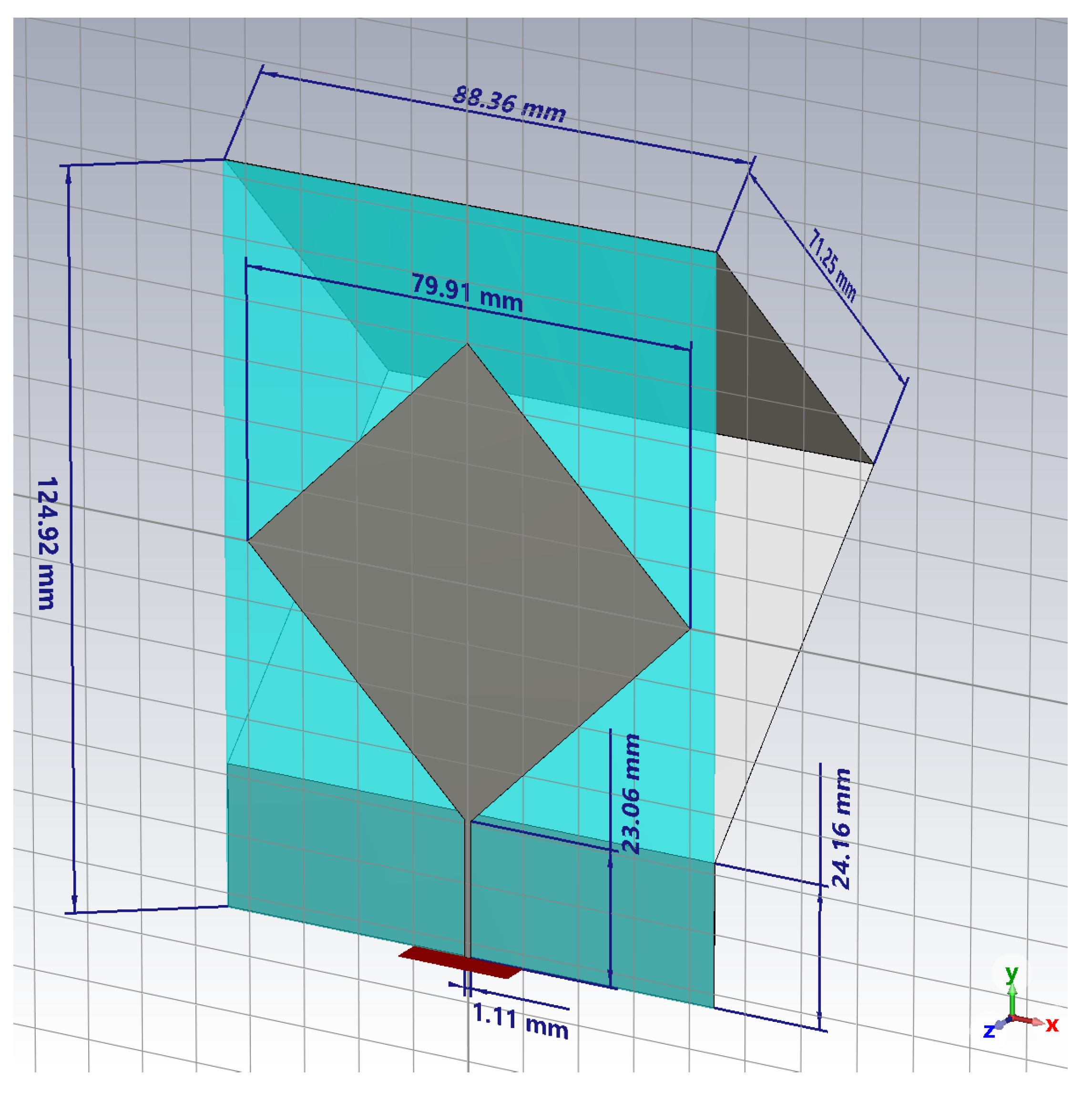
Figure 2.
Simulated reflection coefficient of the antenna.
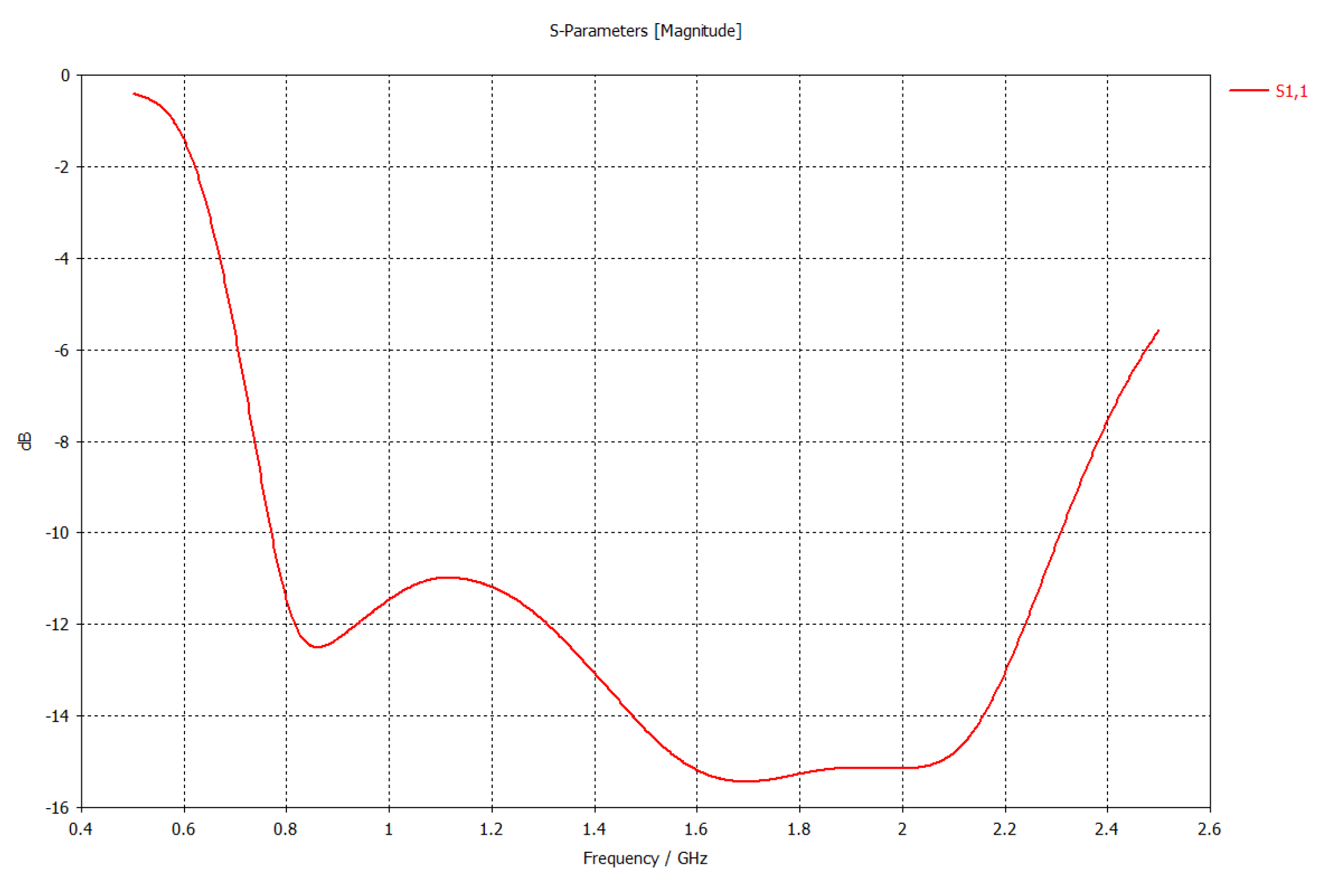
Figure 3.
RMS value of the electric field of the antenna; cut plane, in the middle of the antenna.
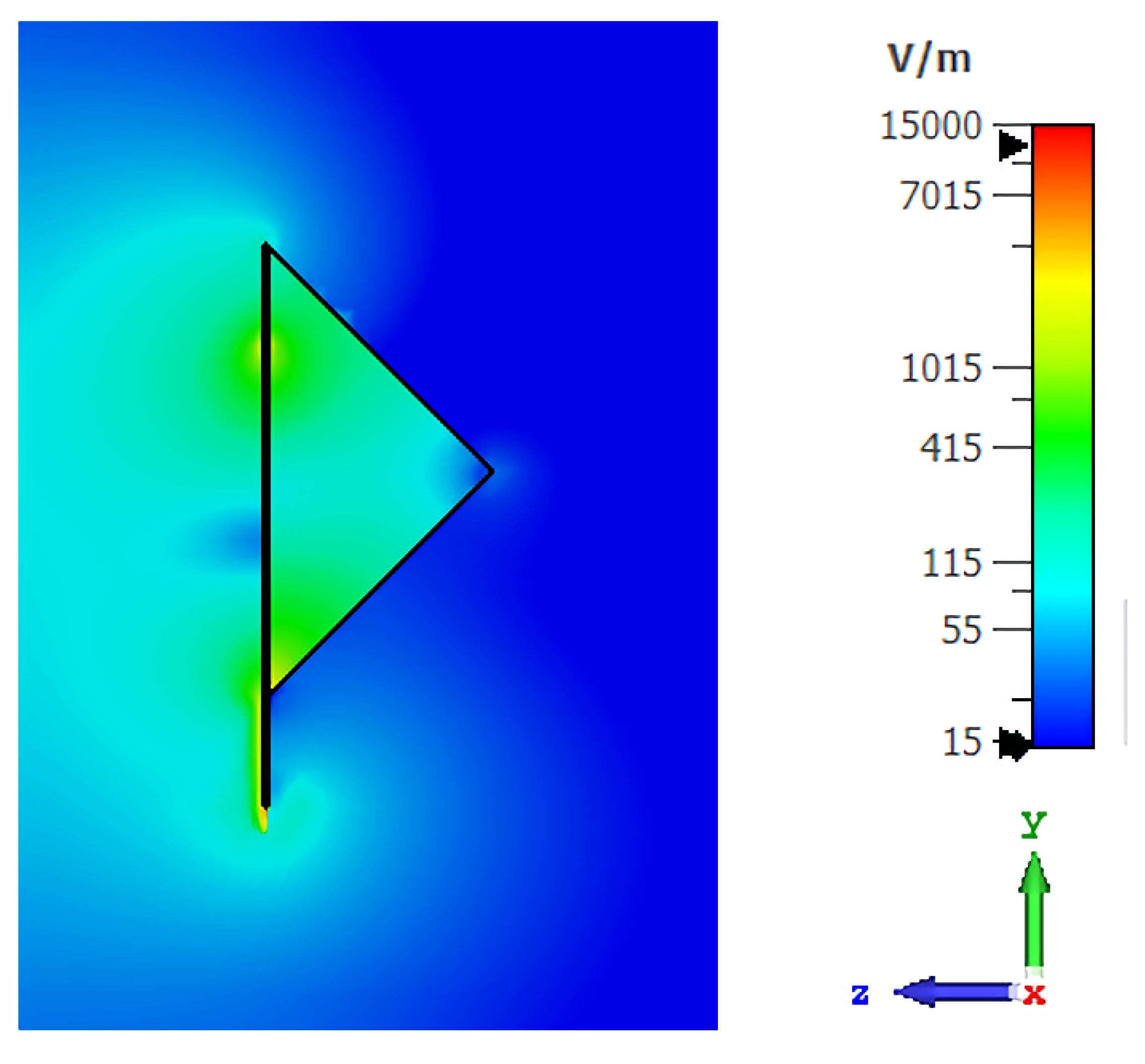
Figure 4.
Radiation pattern of the antenna at the frequency of 1.5GHz.
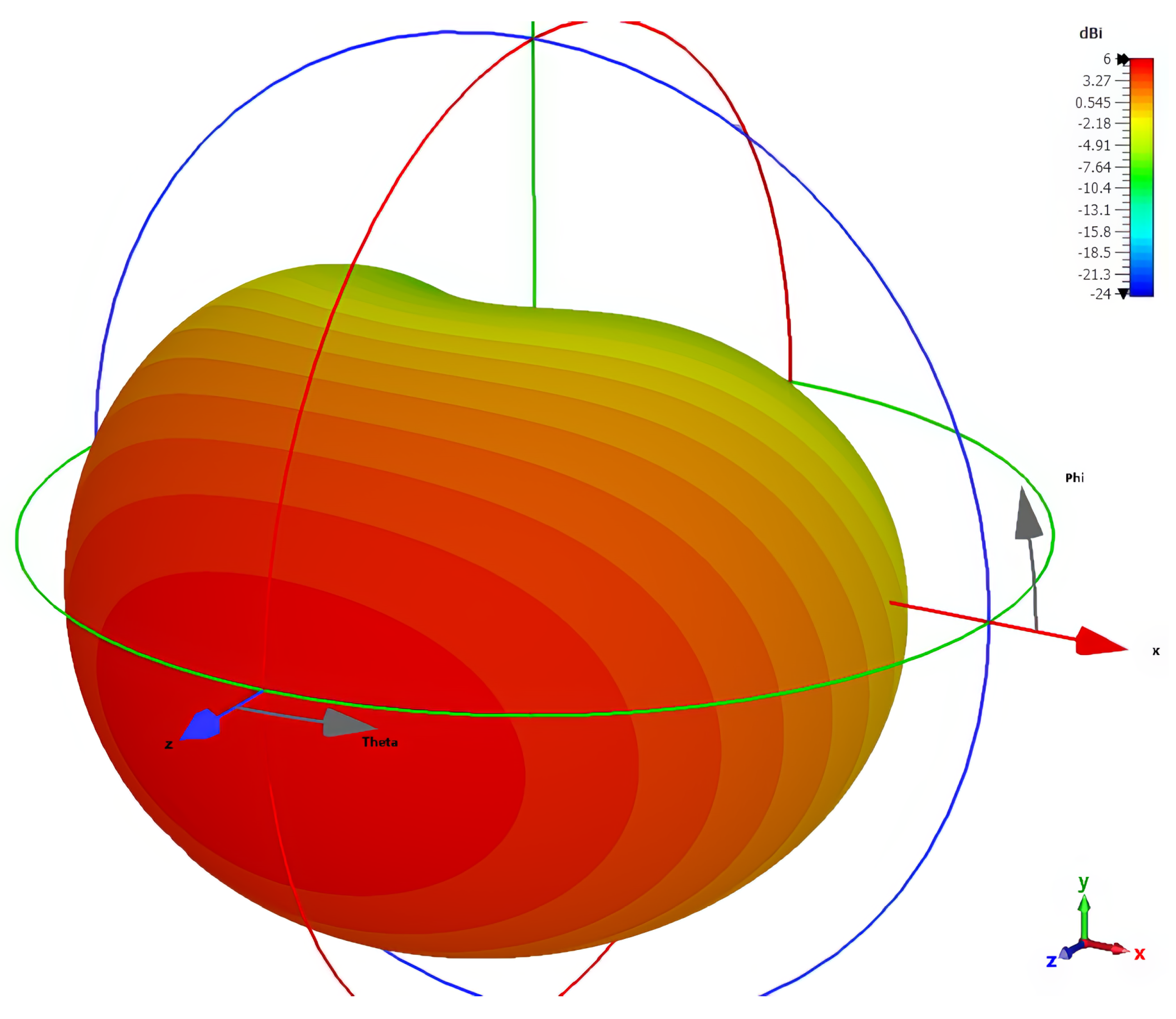
Figure 5.
Variation of the pattern of the antenna in plane for a)1.0GHz, b)1.2GHz, c)1.4GHz, d)1.6GHz, e)1.8GHz and f)2.0GHz.
Figure 5.
Variation of the pattern of the antenna in plane for a)1.0GHz, b)1.2GHz, c)1.4GHz, d)1.6GHz, e)1.8GHz and f)2.0GHz.
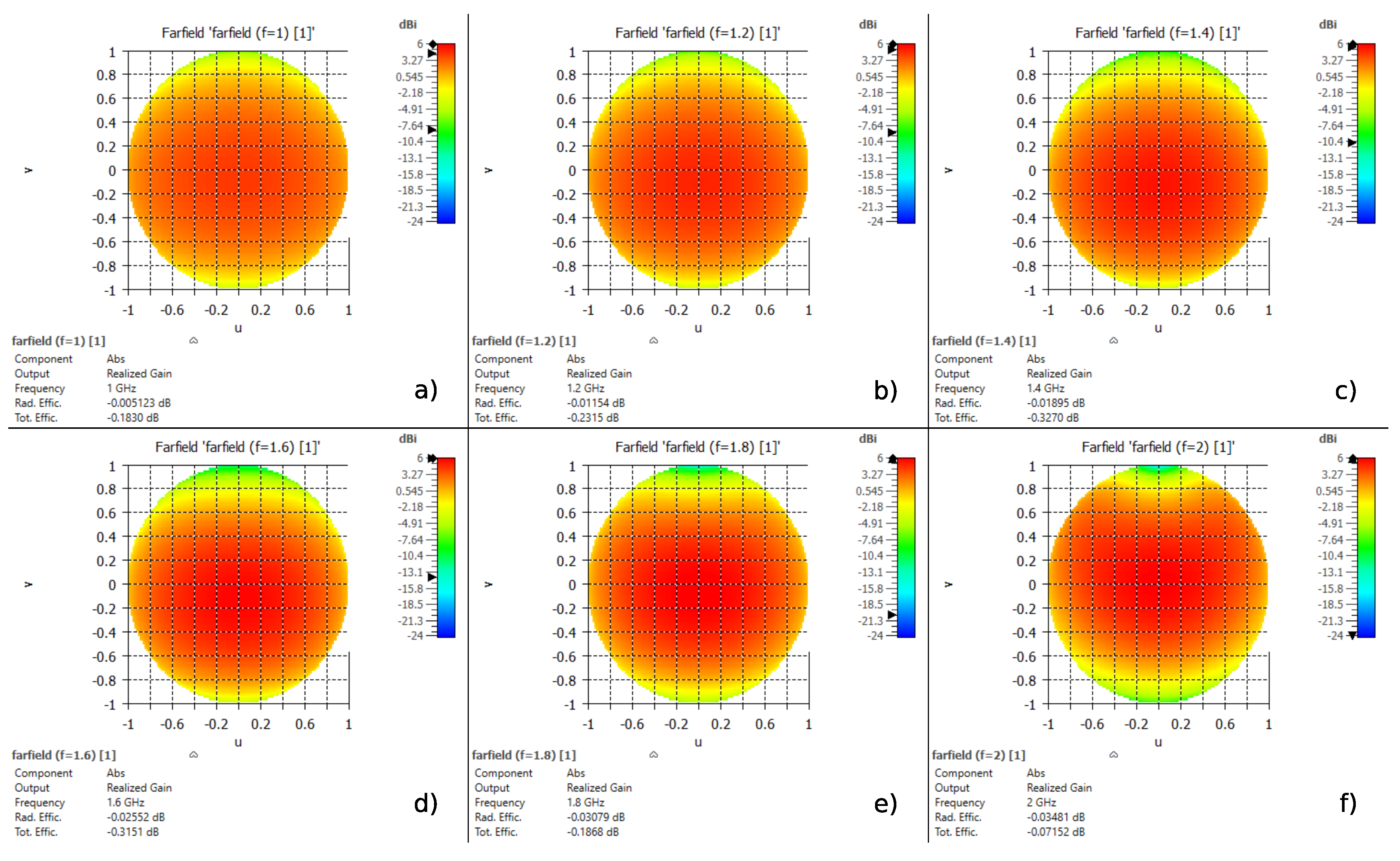
Figure 6.
The connector soldered to the stripline.
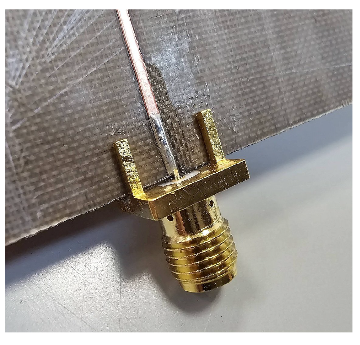
Figure 7.
Photo of the realized prototype; front view of the diamond monopole.
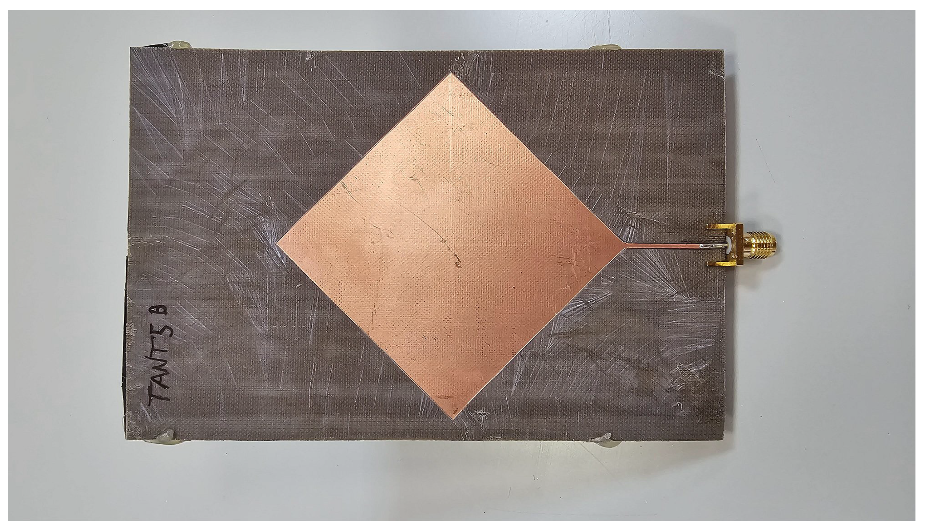
Figure 8.
Photo of the realized prototype; back view of the corner reflector.
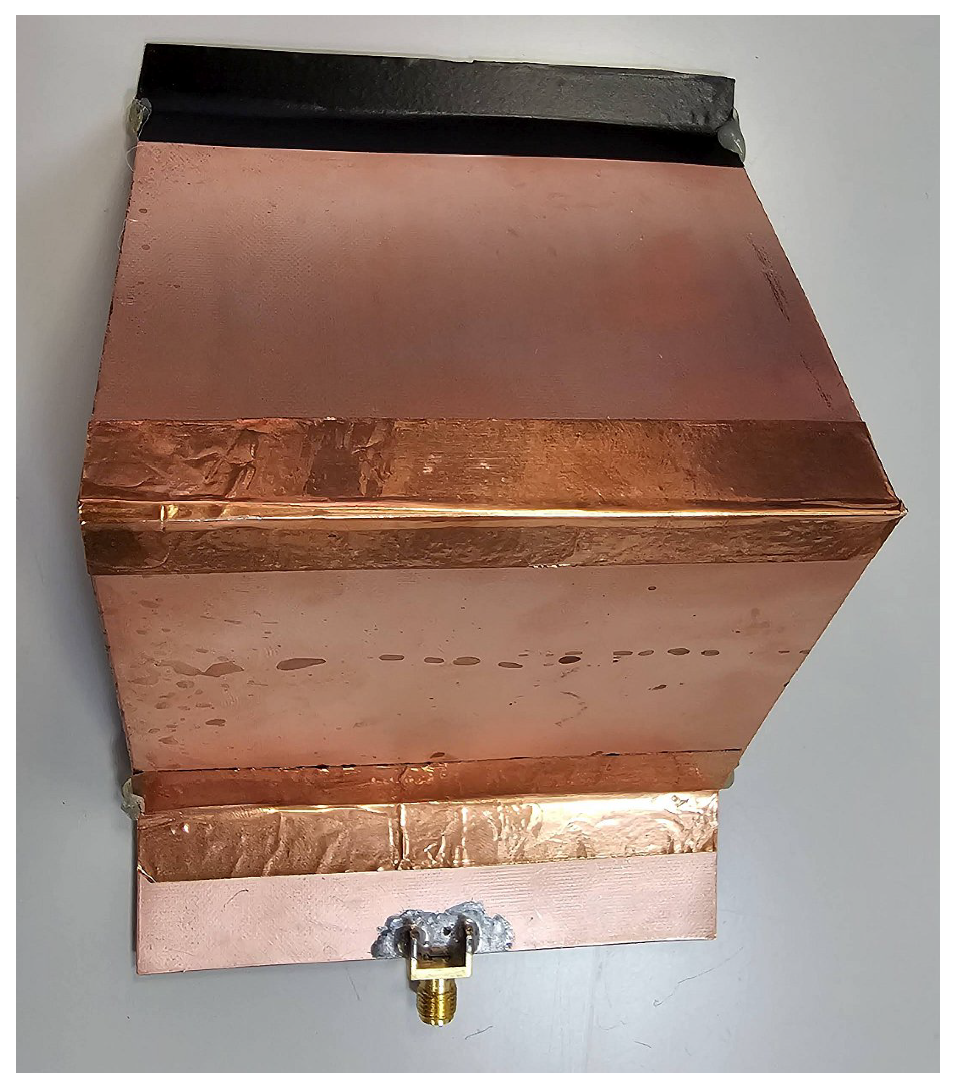
Figure 9.
Photo of the realized prototype; side view of the overall structure.
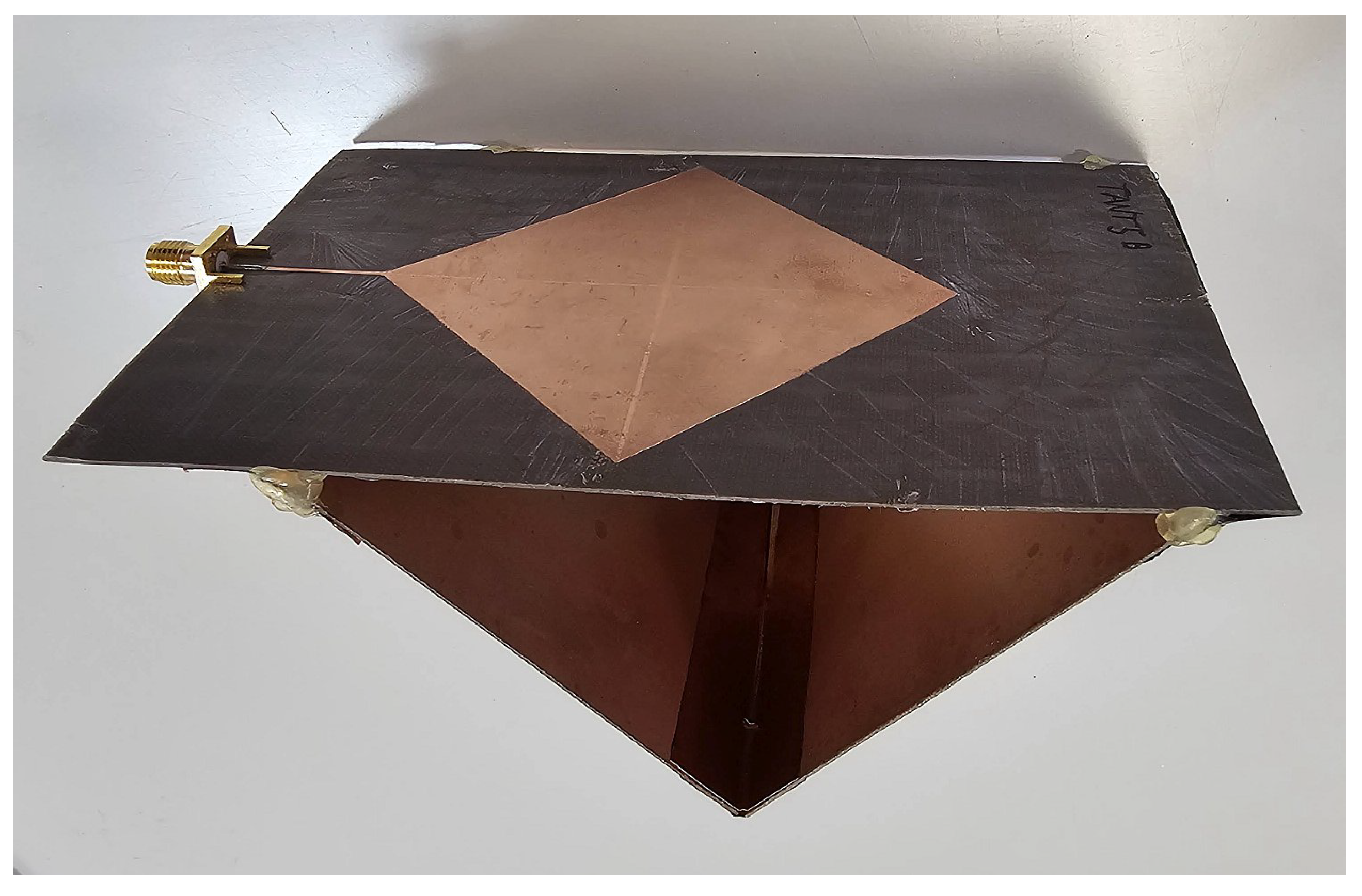
Figure 10.
Measurement of the reflection coefficient of the antenna.
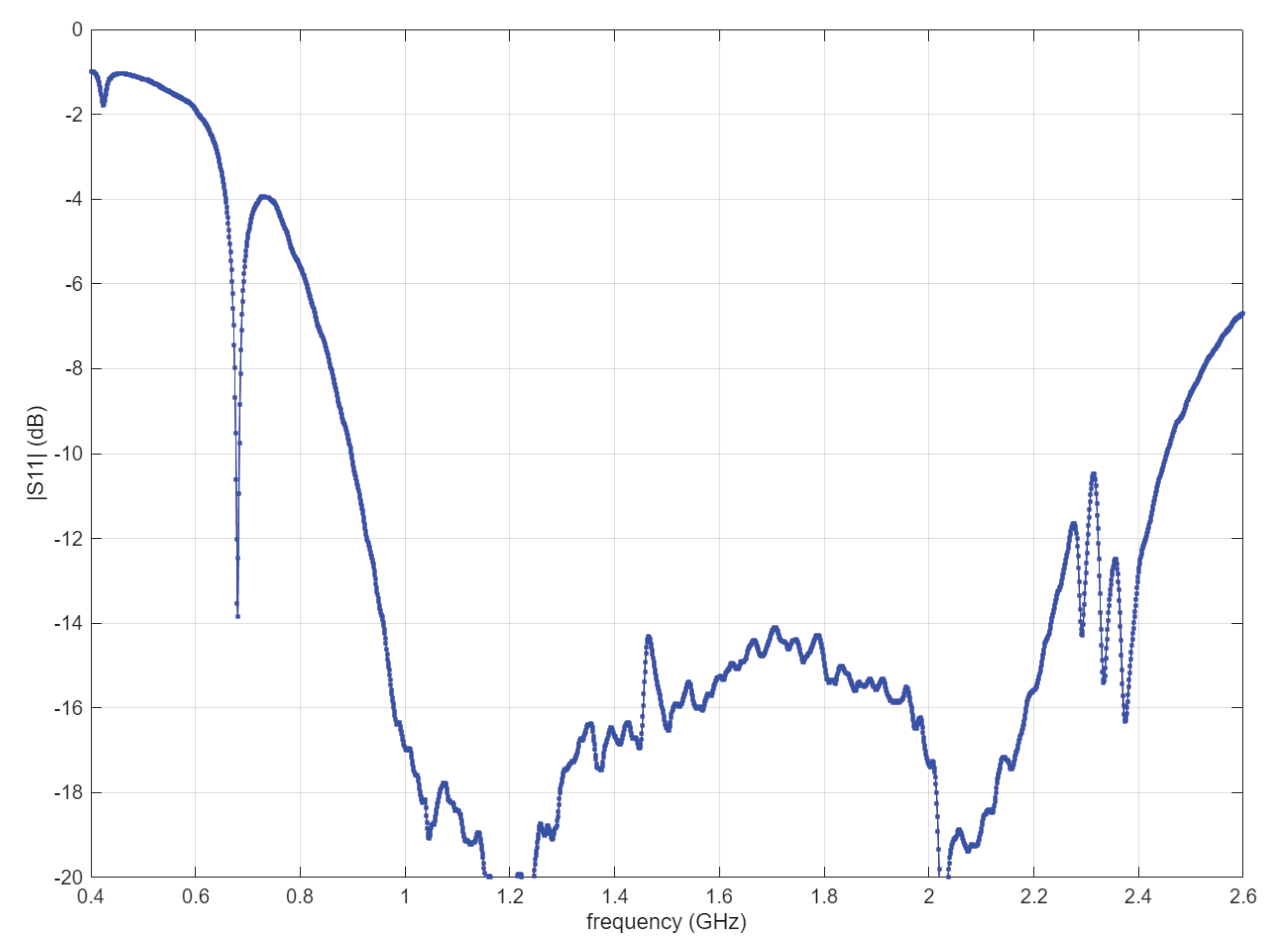

Table 1.
Variation of the maximum gain with frequency.
| Frequency (GHz) | 1.0 | 1.2 | 1.4 | 1.6 | 1.8 | 2.0 |
| Realized Gain (dB) | 4.4 | 5.1 | 5.8 | 6.0 | 6.3 | 6.1 |
Table 2.
Comparison with state-of-the-art UAV GPR antennas/systems.
| Reference | Antenna/System Type | Bandwidth | Weight | Pattern Stability |
| [12] | 3D Printed Horn | 1-4 GHz | ≈180g | Medium |
| [23] | Cavity backed | 2-6 GHz | n.d. | Medium-High |
| [21] | Planar reflector | 0.5-1.3 GHz | n.d. | Medium |
| This Work | Corner Reflector | 1-2 GHz | <40g | High |
Disclaimer/Publisher’s Note: The statements, opinions and data contained in all publications are solely those of the individual author(s) and contributor(s) and not of MDPI and/or the editor(s). MDPI and/or the editor(s) disclaim responsibility for any injury to people or property resulting from any ideas, methods, instructions or products referred to in the content. |
© 2026 by the authors. Licensee MDPI, Basel, Switzerland. This article is an open access article distributed under the terms and conditions of the Creative Commons Attribution (CC BY) license (http://creativecommons.org/licenses/by/4.0/).
Copyright: This open access article is published under a Creative Commons CC BY 4.0 license, which permit the free download, distribution, and reuse, provided that the author and preprint are cited in any reuse.


