Preprint
Article

This version is not peer-reviewed.

Numerical Study of the Dynamic Loads Observed in the Drive Units of Scraper Conveyors Featuring an Innovative Clutch

Submitted:

29 December 2025

Posted:

30 December 2025

You are already at the latest version

Abstract

For many years, the hard coal mining industry has been searching for engineering solutions ensuring greater reliability of the machines operating in difficult underground conditions. The foregoing applies in particular to the scraper conveyors used in longwall systems, started up very frequently and exposed to variable dynamic loads, leading to accelerated wear of powertrain components. The authors of this study have developed a longwall scraper conveyor equipped with a torsionally flexible metal clutch of novel design. The article provides a description of a mathematical model of a conveyor featuring two centrally arranged chains along with a main (discharge) and auxiliary (return) drive, as well as results of the computer simulations performed for two variants of the drive system setup analysed: one with a typical flexible clutch and the other with the innovative torsionally flexible clutch. Analysis of these results has revealed that the solution proposed significantly reduces the amplitude of dynamic loads, which contributes to increased durability and reliability of conveyors under mining conditions.

Keywords: 
;  ;  ;  ;  ;  

1. Introduction

What has been observed for many years in hard coal mining, especially with regard to longwall mining systems, is a demand for drive systems offering increased resistance to loads resulting from operation in difficult underground conditions [1,2,3,4,5]. Some of the machines particularly exposed to intense mining processes are scraper conveyors which, due to the abrasive impact of the material being excavated [6,7,8,9], as well as frequent start-ups and variable dynamic loads [10,11], are subject to accelerated degradation of drive system components, increasing the risk of failure [12,13]. These conveyors represent a crucial element of underground haulage systems, whose availability factor is expected to exceed 95% for longwall conditions [14]. In order to achieve such high reliability, they must be based on structures [15,16,17] designed to ensure increased fatigue strength and resistance to impact loads, while offering reduced dimensions, at the same time.
One of the main operational problems related to scraper conveyors is that of the dynamic forces generated over the course of frequent start-ups and sudden workload changes [18,19,20,21]. In transient states, the above factors cause overloads, increase the amplitude of torsional vibrations, and accelerate the wear of couplings, gear transmissions and chains. Consequently, the drive system durability declines while the likelihood of failure grows.
A typical conveyor drive system [22,23,24,25] features an electric motor, a gear transmission, and a clutch placed between the other two components (Figure 1). The clutch is integrated with the drivetrain, which is why the dynamic modelling of the former requires taking the mass-elastic properties of the other system’s elements into consideration. The clutch protects the motor from the overloads generated by the driven machine, e.g. due to the crushing resistance in crusher systems or the variable resistance attributable to the motion of both the chain and the coal output being hauled [26]. It should limit the dynamic torque on start-up and ensure repeatable start-ups without exceeding the permissible thermal limits. On account of the frequent starts under load and the torque variability under steady-state operation, the clutch must offer adequate torsional flexibility to enable controlled torsional angles, torsional vibration damping, and dynamic stabilisation of the entire system.
A gear transmission operating in a drive system of such a layout is directly exposed to high dynamic loads [27], including moments resulting from abrupt actuator blocking, e.g. the plough head stopping while the body of coal is being mined. The clutches traditionally in use, i.e. rigid, insert-type, and hydrokinetic, offer limited effectiveness in damping these overloads [28,29,30,31,32]. Insert-type clutches (Figure 2), despite their simple design and low cost, do not reduce dynamic loads significantly, while the hydrokinetic ones – although more effective – are characterised by high weight, high price, dependence of operating parameters on the liquid level, and the need to satisfy the ATEX directive requirements.
In response to these challenges, numerous researchers, including the authors of this paper, have been studying new design solutions which are better suited to extreme operating conditions and enable effective minimisation of dynamic loads [33,34]. Particular attention is paid to the development of torque damping systems intended for scraper conveyor drives as well as mechanically flexible components capable of operating under harsh mining conditions. One of the deliverables of this research is the torsionally flexible metal clutch in question (Figure 3), whose operating principle is based on the relationship between the torque value and the axial displacement of clutch components [35,36].
The torque is transmitted from the active side of the clutch [35,36] by means of the shaft (Figure 3a, item 1) to the sliding sleeve (Figure 3a, item 2) via a multiple-start threaded mechanism. An increasing torque causes the shaft to rotate relative to the sleeve and the clutch housing (Figure 3a, item 4), thus producing axial force in the threaded mechanism and initiating plane motion of the sleeve along the shaft axis. The sleeve’s motion is restricted to the axial direction only by a splined coupling (Figure 3a, item 5) between the sleeve and the housing. The sleeve’s displacement results in the compression of an assembly of disc springs (Figure 3a, item 3), adequately selected to achieve the desired clutch flexibility characteristics. Elastic deformation force is generated in the spring system which – when in a state of equilibrium – balances the axial force generated in the threaded mechanism by the running torque. Thus established, the equilibrium defines the momentary position of the sleeve relative to the shaft and the housing, and by that means, also the angle of relative rotation of the active and passive members, at which torque is transmitted. Any momentary overload of the drive system causes additional compression of the springs, while load reduction leads to their relaxation. Once the drive has been completely relieved of load, the sliding sleeve returns to its initial position relative to the clutch shaft axis under the impact of the elastic force produced by the spring assembly.
In order to verify the assumptions underlying the design in practice, the authors built a scraper conveyor prototype adapted for the installation of a torsionally flexible clutch capable of transmitting power of not less than 400 kW. This solution made it possible to run operational tests under conditions close to real-life ones and to assess the effectiveness of dynamic load damping in the drive system.
The conveyor prototype designed by the authors (Figure 4) was subject to detailed laboratory and in-service tests. The goal of these tests was to assess the cooperation between the drive system and the torsionally flexible clutch, and to verify the latter’s impact on the conveyor’s dynamic characteristics. As part of the tests, free and forced vibrations were measured, and a modal analysis was performed to determine the frequency and form of the system’s free vibrations.
The results thus obtained [37,38] have confirmed that the flexible clutch is capable of cooperating properly with the conveyor’s drive system, both being fully compatible in structural and functional terms. It has been concluded that the application of the torsionally flexible clutch reduces both torsional vibrations and dynamic loads in the drive system. The results of the in-service tests and of the modal analysis have shown stable operation of the prototype across the entire rotational speed range, thus rendering the underlying design assumptions effective and confirming that the solution in question can be used in real-life industrial conditions. At the same time, given that the researchers could not install the conveyor at an operating longwall, and that the power of the drive units was insufficient to fully compress the springs, it was not possible to run the tests in genuine real-life conditions, and therefore further studies performed to investigate the properties of the conveyor featuring the innovative clutch were based on mathematical modelling.
Dynamic analysis of the scraper conveyor’s drive system, where the innovative torsionally flexible clutch has been applied, makes it possible to determine not only its dynamic characteristics but also other operational and structural properties, such as maximum load capacity, clutch dimensions, materials to be used, and durability. This is precisely why – if correctly developed and verified – a dynamic model is a valuable machine engineering tool. Such a model should be simple enough to allow practical application and accurate enough to enable a quantitative and qualitative assessment of the dynamic state of the entire drive system.
In numerous cases, it is not only more convenient but also more economically sound to build dynamic models, since the cost, time, and labour intensity of simulations are many times lower than the expenses incurred under fully fledged experimental studies, while making it possible to analyse a broad array of different variants of structural and operational parameters at the same time [39]. This approach enables a preliminary assessment of the behaviour of the drive system under diverse operating conditions, both during start-up and steady-state operation, while the results of time and frequency analyses provide grounds for designing new or modifying existing driven machines.
The main advantage of simulation studies is the capacity to accurately test the response of the entire mechanical system to various forms of dynamic forcing within a wide range of combinations of structural, technological, and operational parameters of the clutch. This makes it possible not only to optimise the system preliminarily, but also to determine with a high degree of precision the parameter ranges which should then be verified under limited experimental studies. Such an approach is completely substantiated from a research point of view, as it enables identification of the key dynamic relationships and prediction of the system’s behaviour under conditions that are difficult to reproduce in a laboratory or under real-life operating conditions [40,41,42,43]. Studies of the dynamic characteristics of scraper conveyors under real-life conditions are particularly costly, difficult, and labour-intensive, which is why most researchers rely on laboratory studies conducted at test benches or numerical simulations [44].
In order to accurately reproduce the actual operating conditions of a conveyor, joint simulation methods are often applied, employing software suites such as ADAMS, EDEM, ANSYS, or MATLAB/Simulink. Such an approach enables accurate reproduction of material motion, interactions between chain links, and the operation of the entire drive system. For example, Swider et al. [45] developed a simulation model of a conveyor drive system based on ADAMS-Simulink, demonstrating the dependence of torque on motor load and current. Wang et al. [46] used the MBD-DEM-FEM simulation to analyse the motion of a conveyor and the forces acting on the chain links under clamping conditions. Zhang et al. [47] created a three-dimensional model of a plough in the ANSYS and SolidWorks environment to optimise structural reinforcements which improved the machine’s mechanical properties and extended its service life.
In order to increase the accuracy of models, the researchers applied various discretisation methods and different combinations of system elements, e.g. a model of chain segments linked with the use of the Kelvin-Voigt model, enabling dynamic analysis of sagging in the centre groove [48]. Shprekher et al. [49,50] developed a multi-mass model comprising a motor, a reduction gear, and a drive wheel, making it possible to simulate start-up under full and no-load conditions. Zhang et al. [51] created a dynamic multi-body model, which they verified by measuring deformations at fixed points, and introduced a method for estimating the stress distribution in the chain. At the same time, experimental studies of conveyor drive systems were conducted. Jiang et al. [52,53,54] developed a test rig to monitor the speed difference between drive wheels at different chain speeds, loads and terrain configurations, which allowed them to identify key factors affecting the system dynamics, such as chain tension and the frequency of secondary meshing of the reducing gear. The problem of modelling and testing of the dynamics of scraper conveyors was also analysed in studies [55,56,57,58,59,60,61,62,63].
The overall body of research conducted by Dolipski and Sobota [64,65,66,67,68,69,70,71] to date shows that dynamic modelling of scraper conveyors is crucial for assessing the behaviour of the entire drive system under the conditions of variable loads, frequent start-ups, and high resistance to motion. The authors analysed the dynamics of clutches, both hydrokinetic and torsionally flexible, as well as the interaction between actuators, including plough assemblies, enabling identification of torsional vibrations, overloads, and the dynamic properties of an entire conveyor.
What these models allow for is not only assessment of the system’s behaviour under various operating conditions, but also analysis of the impact of the structural and operational parameters of clutches on the operating stability and durability of the drive unit. This makes it possible to optimise the clutch flexibility characteristics, project dynamic moments across the entire system, and design drive systems with increased resistance to overloads and vibrations. When analysing the dynamics of scraper conveyors, vibration damping related problems are also considered important [72].
A similar approach was adopted in the study addressed in this paper, as a mathematical model of the entire conveyor was developed by taking the new torsionally flexible metal clutch into account. This made it possible to verify in numerical terms the impact of the clutch on the reduction of dynamic loads and the torsional vibration damping in the drive system while assuming conditions typical of mining operations.
The main objective of the study was to perform numerical examinations of the dynamic properties of a scraper conveyor by developing a mathematical model of the drive system with the new torsionally flexible metal clutch and to determine the dynamic forces acting under diverse operating conditions. The novel aspect of the study is the assessment of the effect of the clutch in question on the reduction of dynamic loads as well as on the damping of torsional vibrations in the entire drive system compared to traditional flexible clutches. The results of the analyses performed make it possible to verify the effectiveness of the design assumptions adopted and to provide a solid foundation for further research and design of conveyors offering increased reliability and durability under difficult mining conditions.

2. Materials and Methods

2.1. Assumptions for the Mathematical Model of the Scraper Conveyor

For purposes of numerical verification of the impact exerted by torsionally flexible metal clutches on conveyor dynamics, a mathematical model of the complete drive system featuring such a clutch was developed. The model was based on previously verified dynamic models of scraper conveyors [67,68] as well as on a model of a drive system equipped with a flexible clutch [35].
Simulation tests were performed using a discrete mathematical model of a double-chain conveyor with a main and auxiliary drive unit supported by dedicated computer software intended for solving systems of differential equations describing motion and for numerical analyses. The motion in the upper and lower conveyor branches as well as in the main and auxiliary drive units was described using a system of ordinary second-order differential equations.
In order to develop the relevant physical model, a number of simplifications and assumptions had to be adopted [67,68], including the following:
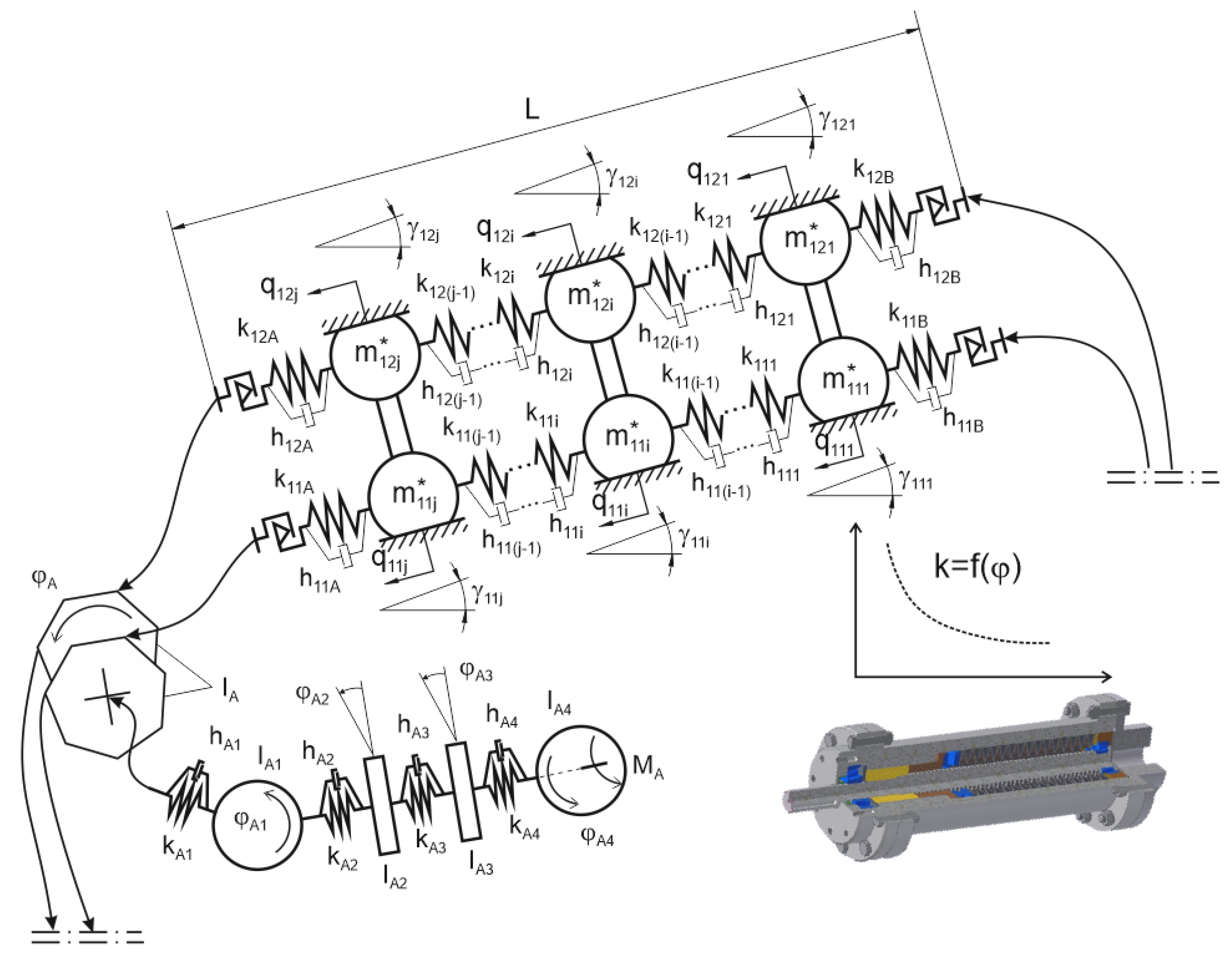
the upper branch chains were replaced with a finite number of concentrated masses connected by elastic massless bonds and contact elements; the mass of each section was concentrated in its centre, also taking scrapers and coal output into account,
the lower branch chains were replaced with a finite number of concentrated masses connected by elastic massless bonds and contact elements; the mass of each section was concentrated in its centre, also taking scrapers and pulverised fine coal into account,
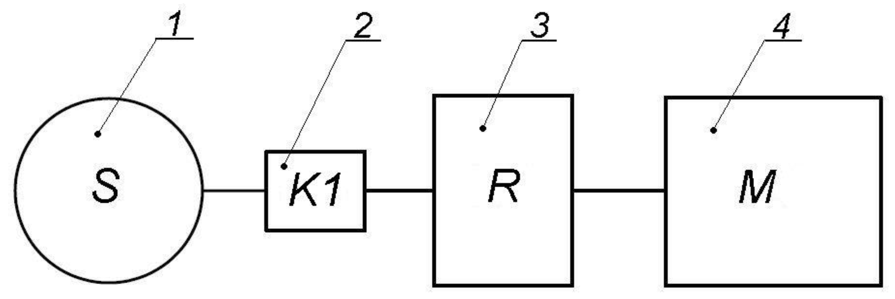
the drive systems were replaced with rigid polygons, modelling the operation of chain wheels, linked with solids of revolution via viscoelastic bonds,
the following moments of inertia were reduced for the polygons and solids of revolution:
  • moment of inertia of the chain drum (IA, IB) and the gear transmission (IA1, IB1),
  • moment of inertia of the output element of the torsionally flexible metal clutch seated on the high-speed transmission shaft (IA2, IB2),
  • moment of inertia of the input element of the torsionally flexible metal clutch seated on the high-speed transmission shaft (IA3, IB3),
  • moment of inertia of the drive motor rotor (IA4, IB4).
Thus constructed, the model enables simulation tests of the entire conveyor, taking into account the effect of the torsionally flexible metal clutch on torsional vibration damping, the distribution of dynamic moments, and the response of the entire drive system to variable operating conditions. The model provides a solid foundation for assessing the effectiveness of the novel clutch against that of traditional flexible solutions, as well as for further design work on conveyors offering increased reliability and durability under harsh mining conditions.

2.2. Dynamic Scraper Conveyor Model

Following the formalisation of the dynamic phenomena occurring in the physical model of a high-performance double-chain scraper conveyor, featuring a main and auxiliary drive unit, equipped with two torsionally flexible metal clutches, a mathematical model of the machine was developed. This model constitutes a system of nonlinear ordinary differential equations of the second order [73].
The dynamic model thus created comprises a single main drive and an auxiliary drive, each equipped with a torsionally flexible metal clutch. Engineered in such a manner, the model makes it possible to analyse the dynamic phenomena observed in the entire conveyor drive system (Figure 5).
The dynamic model described above enables simulation studies to be conducted in the following areas:
the effect of the torsional stiffness of the torsionally flexible metal clutch on the dynamic loads in the conveyor,
the effect of the damping properties of the metal clutch on the behaviour of dynamic loads,
the effect of the conveyor parameters and external loads on the operational dynamics of clutches.
The results of the foregoing studies can be utilised as grounds for selecting the optimal configuration of drive characteristics for a specific conveyor and clutch parameters, including: spring assembly setup, number and type of springs, geometric dimensions of the clutch, and the angle of inclination of the thread helix.
Based on the dynamic model of the double-chain conveyor developed by the authors, including a main drive (A) and an auxiliary drive (B), simulation tests were conducted for one state of tension of the scraper chain. Two clutch types were analysed:
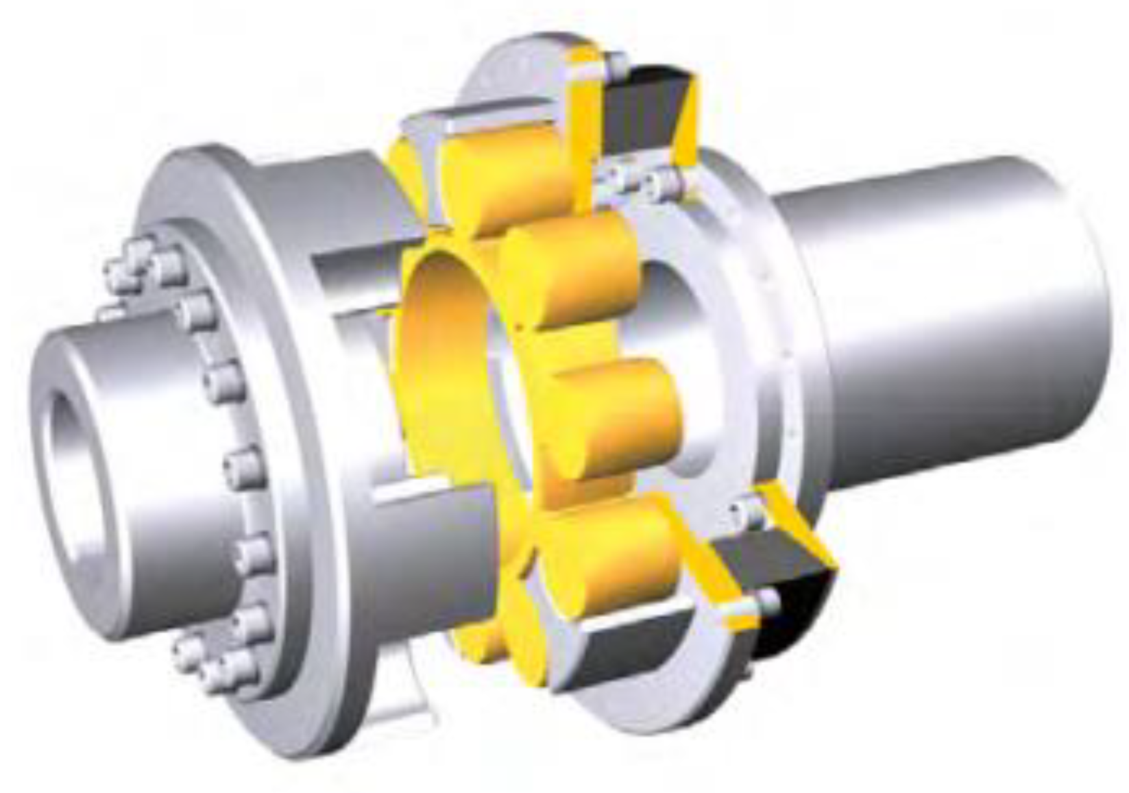
flexible insert-type clutch (FC),
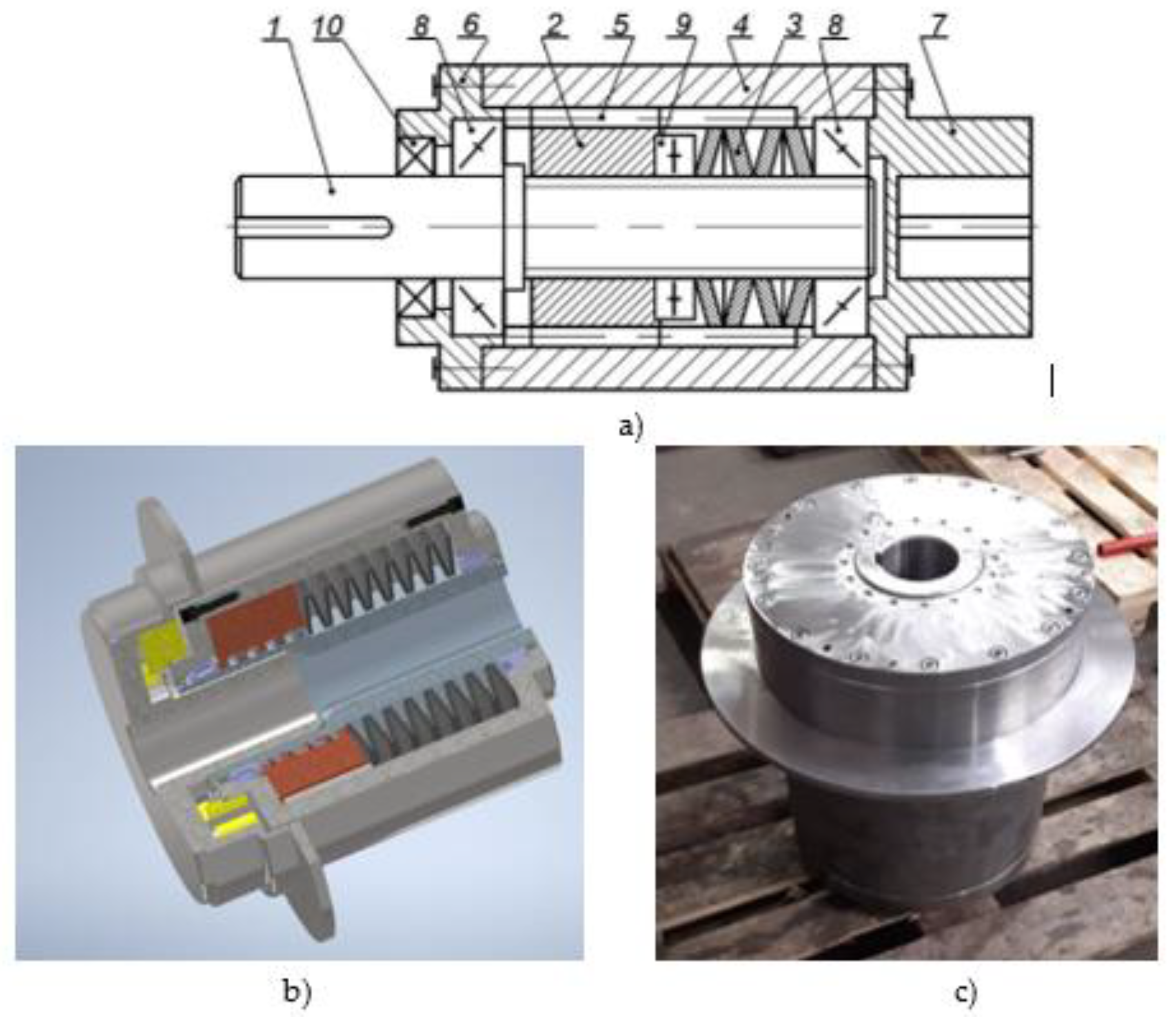
torsionally flexible metal clutch (TFC).
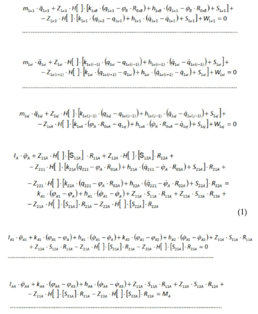
The characteristics obtained in such a manner made it possible to assess the impact of the clutch type on the dynamic loads affecting the conveyor as well as on torsional vibration damping, which had provided grounds for further design work aimed at increasing the reliability and durability of conveyors intended to operate under harsh mining conditions.
Equation (1) represents the mathematical notation of the equations of motion applied in the said model, used to test the conveyor featuring the torsionally flexible metal clutch. Such a notation enables quantitative and qualitative analysis of the dynamic behaviour of the conveyor’s drive system, including the impact of the newly designed clutch on the reduction of dynamic loads and on torsional vibration damping.
Preprints 192043 i001
i = 2, 3, ... , j-1
κ = 1, 2
where:
j - number of sections into which the upper and lower conveyor branches were divided in the physical modelling process,
κ - numerical chain designation; for a double-chain conveyor, this is either 1 or 2,
h - equivalent damping coefficients,
k - specific stiffness of elastic bonds,
q - translation coordinates,
ϕ - rotation coordinates,
R - radiuses of chain run-up onto the chain drum and radiuses of chain run-off from the drive drum,
H[] - Heaviside function,
S - static loads in the drive chain,
Z - coefficient determining the point of the drive chain breakage,
I - moments of inertia of the masses rotating in the drive systems,
M - driving torque of asynchronous motors in the main and auxiliary drive systems.

2.3. Methodology for Dynamic Scraper Conveyor Simulation

The dynamic simulation of the scraper conveyor was performed using proprietary computer software composed of three modules: a pre-processor, a solver, and a post-processor. The pre-processor and post-processor were developed in a database management system (DBMS), enabling effective management of model parameters and simulation results. The pre-processor is intended to prepare input files for the solver, defining all geometric and mechanical parameters as well as initial conditions of the conveyor components, including torsionally flexible metal clutches and drives. The post-processor is used to process calculation results, generating time characteristics and dynamic analysis reports.
The solver was deployed as a separate executable file in Embarcadero’s Delphi environment. Delphi was chosen on account of the high performance of the machine code it generates, which proves crucial when solving complex systems of nonlinear differential equations of the second order. The system of equations describes the dynamics of the masses concentrated in the conveyor branches, drive units, and torsionally flexible metal clutches, and it is solved by the Runge-Kutta-Fehlberg method (RKF45) with an adaptive time step. This method automatically adjusts the calculation step to maintain the pre-set local error, ensuring simulation stability and accuracy over a wide range of dynamic loads.
The results were analysed using the Matlab environment from Mathworks, enabling visualisation of the time characteristics, dynamic loads, and torsional vibrations in the conveyor drive system.
On account of the complexity of the mathematical model, three-element indices were used to uniquely identify each dynamic quantity in the model: the first character denotes the conveyor branch (1 – upper, 2 – lower), the second character denotes the chain number, and the third character denotes the position in the chain outline. The letters A and B refer to the main (discharge) and auxiliary (return) drive units, respectively. Having assumed such a convention, one can accurately assign dynamic parameters to individual elements and efficiently configure simulations for different drive system variants.

2.4. Model Input Data

The scraper conveyor assumed for the numerical studies was characterised by the following parameters:
conveyor length: 230 m,
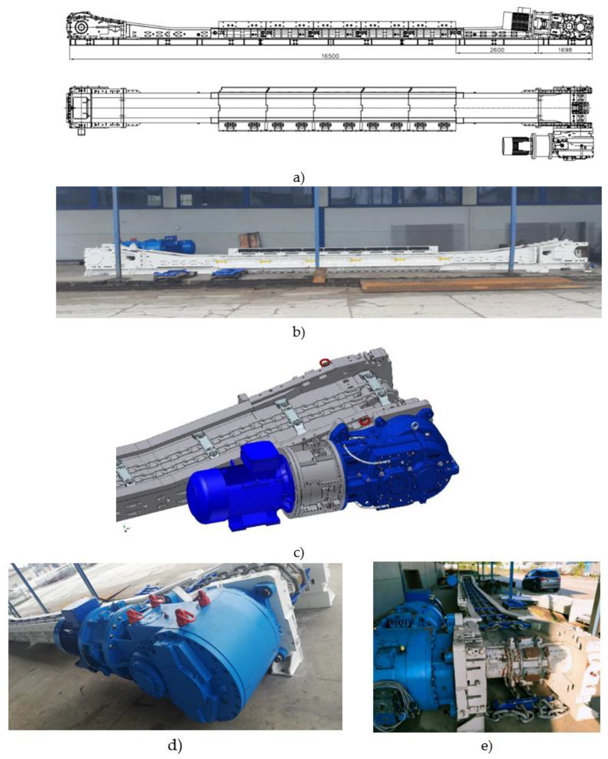
drives: main and auxiliary, each with a 315 kW asynchronous motor,
evenly distributed coal output: 170 kg/m,
heading inclination: 0°, lower branch unloaded,
34×126 link chain of constant stiffness along the entire outline,
identical mechanical characteristics of the motors,
simultaneous activation of motors in both drives,
no variation in the pitch of the scraper chain links,
values of torsional stiffness and damping of the drive system featuring the torsionally flexible metal clutch taken from previously defined ranges (see section 6.5).
The mathematical model of the conveyor takes two types of clutches into account:
flexible insert-type clutch, used in the main and auxiliary drives,
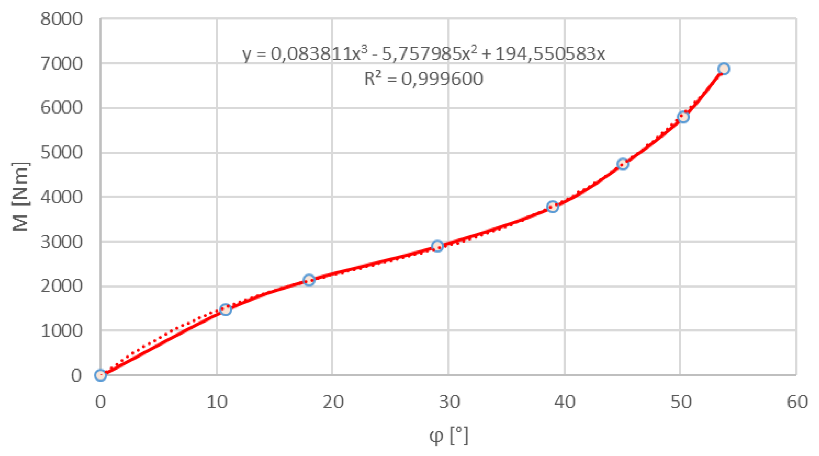
torsionally flexible metal clutch, introduced into the model by way of the characteristics obtained in the experimental studies (Figure 6).

3. Results and Discussion

Figure 7 and Figure 8 show the characteristic curves of the angular velocities of the chain drums and the dynamic loads of the clutches operating in the main drive (blue) and auxiliary drive (red) in the conveyor subject to tests, relative to time, for setup no. 1 and setup no. 2, respectively. In both setups analysed, the conveyor start-up time was less than 5 seconds. The harsh conveyor start-up was attributable to the very high load of the coal output hauled on the upper branch. The assumption adopted for purposes of the computer simulation was that the output would be transported at a rate of 500 kg/m. The significant irregularities observed in the angular velocities of the drive chain drums during the conveyor start-up represent a familiar phenomenon [74]. They usually occur in conveyors of considerable length, loaded by a stream of coal output transported at a very high rate. Where this is the case, and especially during machine start-ups, excessive elastic chain elongation occurs, accumulating at the point where it runs off the drive drums in the main and/or auxiliary drive.
Figure 9 shows the curves of the dynamic load observed in the upper branch of the chain at the point where it runs up onto the chain drum in the main drive (blue) and at the point where it runs off the chain drum in the auxiliary drive (red).
For the time characteristics of the dynamic loads observed in the chain at the point where it runs up onto the chain drum in the main drive, amplitude spectra were established. They have been provided in Figure 10. The spectrum determined for the conveyor version featuring a conventional insert-type clutch has been shown on the left-hand side, while the right-hand graph corresponds to the spectrum established for the machine equipped with the highly flexible clutch, representing setups no. 1 and 2, respectively.
The time characteristics obtained in the numerical tests of a 230 m long scraper conveyor loaded with coal output along its entire length made it possible to assess the effectiveness of the torsionally flexible metal clutch installed in the machine’s drive units. The following quantities were assumed as the clutch assessment criteria (Table 1):
maximum load torque of the clutch in the main drive (MSPA,max) and (peak-to-peak) amplitude of this load (AMSPA) (Figure 7b and Figure 8b – blue),
maximum load torque of the clutch in the auxiliary drive (MSPB,max) and (peak-to-peak) amplitude of this load (AMSPB) (Figure 7b and Figure 8b – red),
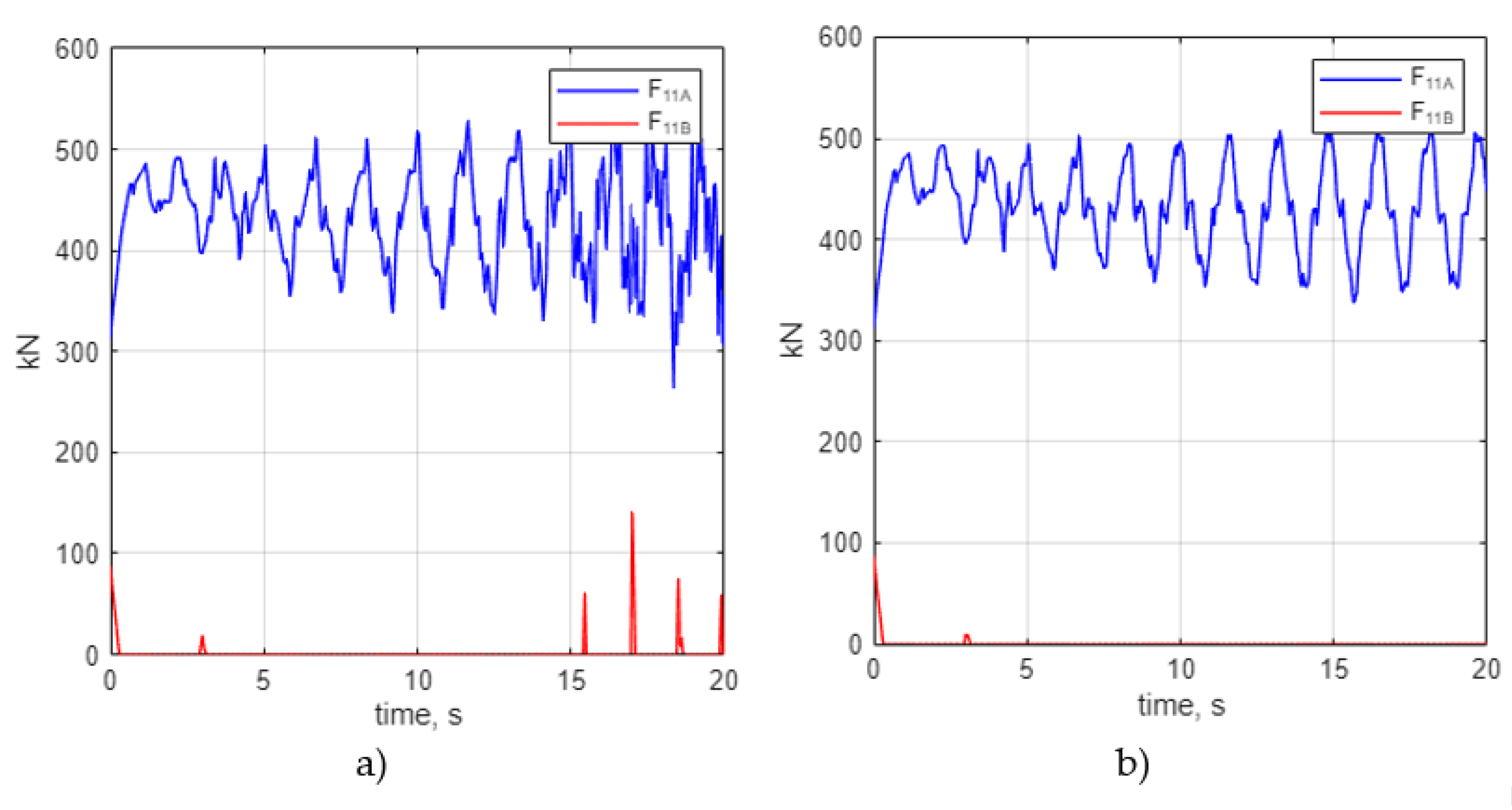
maximum value of the dynamic load in the chain at the point where it runs up onto the chain drum in the main drive (F11A,max) and the amplitude of this load (AF11A) (Figure 9 – blue).
The numerical studies performed on a 230 m long scraper conveyor loaded with a stream of output hauled at a high rate (500 kg/m) made it possible to conduct a detailed analysis of the dynamics of the system during start-up as well as to assess the impact of the type of the clutch installed in the machine’s drive units. Thus obtained, the time characteristics of the angular velocities of the chain drums and of the dynamic loads affecting the clutches (Figure 7 and Figure 8) clearly imply significant motion irregularities in the initial phase of operation. Their main cause is probably the accumulation of elastic elongations of the chain, especially in the zone where it runs off the auxiliary drum. This phenomenon is also evident in the chain load profiles shown in Figure 9.
The analysis of the dynamic loads observed in the chain (Figure 9) revealed explicit differences between the two drive system setups subject to tests. In setup no. 1, featuring a conventional flexible clutch, short-lived, yet evident, load peaks were observed, implying periodical chain slackening. In setup no. 2, where a metal clutch of high torsional flexibility was used, there was virtually no complete slackening, which can be attributed to more effective vibration damping and smoother torque transmission.
Under operating conditions, the slack between chain links tends to accumulate at the auxiliary drive, which contributes to the phenomenon of scraper chain slackening. As shown in the numerical graphs, this condition manifests itself as the sections of the dynamic chain load curve in the zone where the chain runs off the auxiliary drum, coinciding with the horizontal axis of the coordinate system (Figure 9b). Furthermore, the short-term force peaks observed in some configurations (Figure 9a) imply periodical chain slackening, which is highly detrimental to both drive systems and the service life of the chain itself.
The application of the metal clutch of high torsional flexibility (setup no. 2) significantly changed the dynamic characteristics of the drive system. Owing to its increased torsional flexibility, this clutch effectively acts as a high-performing torsional vibration damping element, limiting the transmission of rapid torque changes between the motor and the chain drum. The foregoing was confirmed by the results of the spectral analysis of the chain loads (Figure 10), where setup no. 2 showed a clear reduction in the amplitudes of the three main frequency components and a notable disturbance reduction in the higher frequency range. This means that the equivalent stiffness of the drive train is reduced and that the clutch is more capable of straining elastically and – by that means – supressing vibrations. Consequently, the novel clutch solution effectively limits the propagation of torsional vibrations to the chain and improves the stability of the entire system.
The data compiled in Table 1 clearly confirm the effectiveness of the clutch with increased torsional flexibility. The largest relative reductions apply to clutch load amplitudes AMSPB (85.6%) and AMSPA (49.8%), which shows how greatly the oscillatory nature of the load torques is reduced. The smaller, yet significant, reduction in maximum torque values (21.5% for MSPA,max and 6.3% for MSPB,max) indicates that the clutch is also effective in decreasing maximum peak loads, albeit to a lesser extent than the amplitudes of cyclic vibrations.
In terms of the dynamic chain loads, the application of the torsionally flexible metal clutch resulted in a 41.3% reduction in the amplitude of force AF11A and an 8.5% reduction in the maximum value of F11A,max. The higher reduction of the amplitude than of the maximum value implies that the clutch primarily suppresses the oscillatory components responsible for the occurrence of local dynamic overloads, while the overall level of forces associated with the mass of the output stream being hauled remains limited by the mass-geometric characteristics of the system.
The torsionally flexible metal clutch applied in setup no. 2 has significantly improved the dynamic properties of the conveyor by:
reducing the irregularity in the angular velocity of the drums,
limiting the chain slackening phenomenon,
strongly damping torsional vibrations,
reducing peak as well as amplitude loads in both the clutches and the chain.

5. Conclusions

As part of the study, a detailed dynamic model of a scraper conveyor equipped with a torsionally flexible metal clutch (TFC) has been developed and analysed. The model comprises both the most essential elements of the drive system, such as the chain, drums, transmission and clutch, as well as the dynamic phenomena related to variable loads and transient states. Due to technical and logistic constraints, it was not possible to conduct fully-fledged tests of the prototype under real-life mining conditions, which is why the effectiveness of the TFC was assessed by way of advanced computer simulations. The results obtained under various analyses have made it possible to assess the performance of the clutch in terms of dynamic load reduction and to confirm the utility value of the chosen design parameters of individual drive system components.
What the analyses have revealed, and explicitly evidenced, is that the torsionally flexible metal clutch (setup no. 2) ensures reduction of the dynamic effects associated with the conveyor operation, which makes it a solution particularly recommended for drive systems exposed to high dynamic loads.
Based on the numerical studies of a 230 m long scraper conveyor operating under heavy duty conditions (haulage rate of 500 kg/m), the following conclusions have been drawn:
  • The conveyor dynamics on start-up are significantly conditioned by the torsional flexibility of the clutch.
  • The application of a metal clutch characterised by increased flexibility has effectively eliminated the phenomenon of chain slackening.
  • Offering higher torsional flexibility, the clutch ensures adequate damping of torsional vibrations.
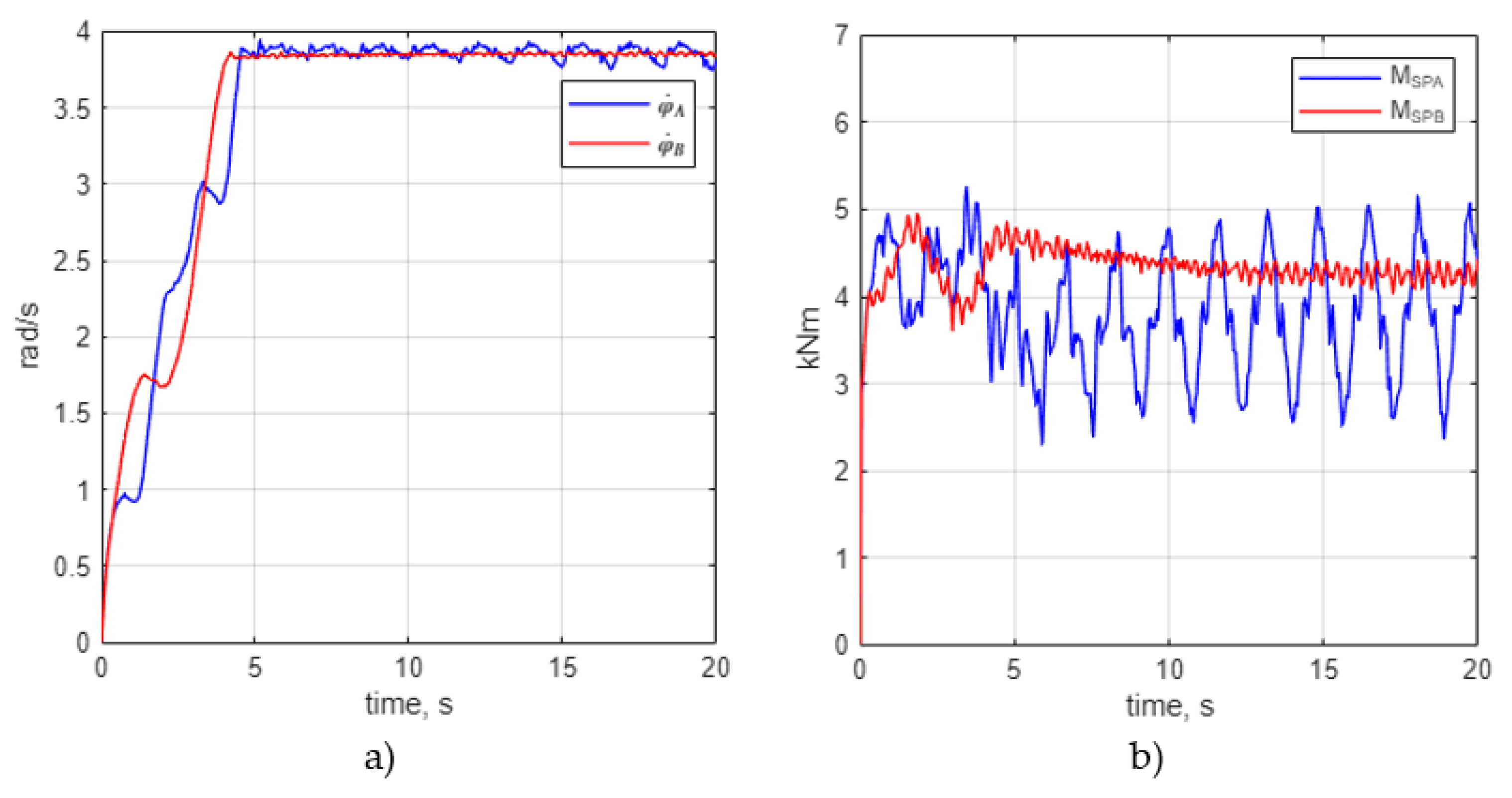
  • In setup no. 1 (typical mining clutch), evident irregularities were observed in terms of the angular velocity and chain slackening in the auxiliary drive area.
  • In setup no. 2 (highly flexible clutch), no force behaviour typical of periodic chain slackening was observed in the section where the chain runs off the drum.
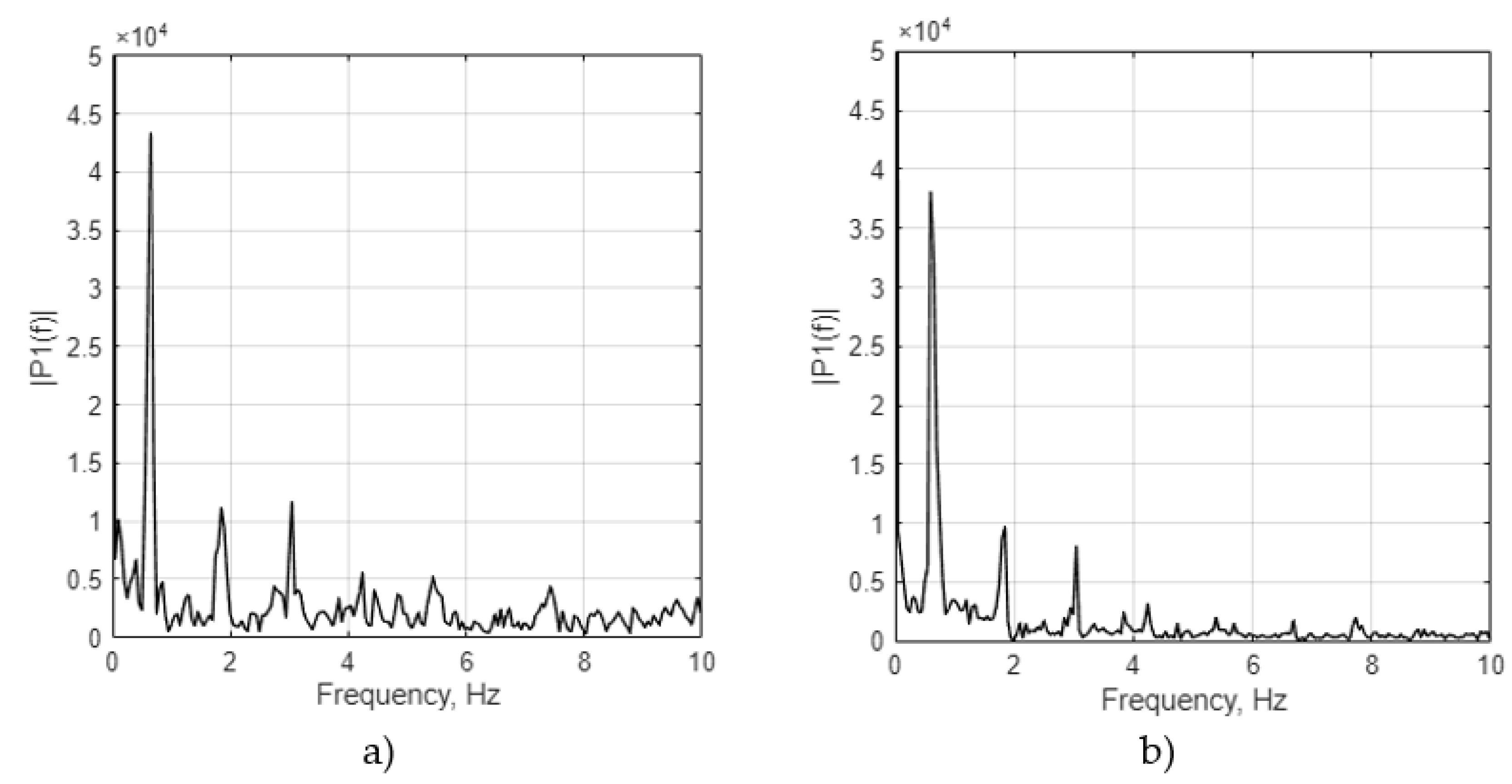
  • Spectral analysis has revealed reduced amplitudes of the three dominant frequency components and a decrease in the intensity of high-frequency disturbances.
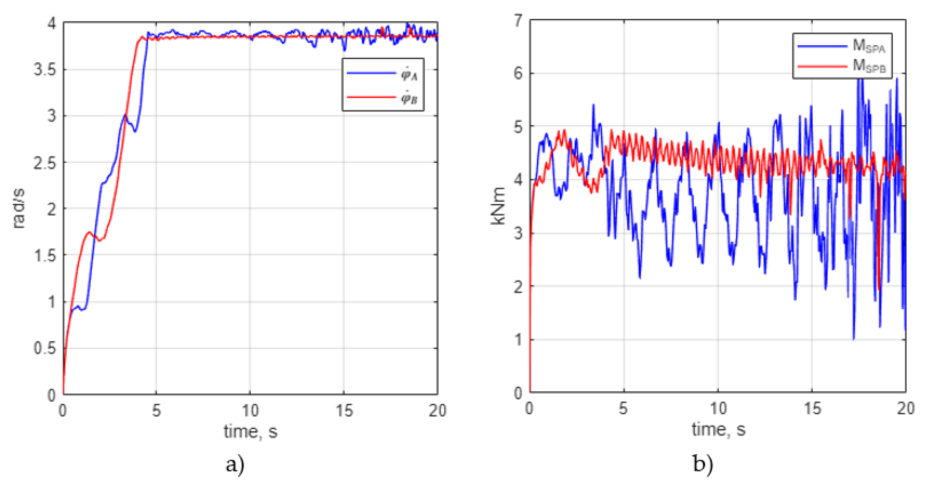
  • The application of the flexible metal clutch has effectively decreased the amplitude of the maximum load torque of the clutch operating in the auxiliary drive (AMSPB) – by as much as 85.6%, as well as in the main drive (AMSPA) – by 49.8%, while the maximum load torque of the main drive (MSPA,max) was reduced by 21.5%, and that of the auxiliary drive (MSPB,max) – by 6.3%.
  • The amplitude of the dynamic loading force affecting the conveyor chain at the point where it runs up onto the chain drum (AF11A) was reduced by 41.3%, while the maximum force acting in the main drive (F11A,max) dropped by 8.5%.

Author Contributions

Conceptualization, A.N.W., K.F. and E.R., methodology, M.K., E.R. and K.F..; investigation, E.R. and M.K.; formal analysis, F.K. and R.B., resources, M.K. and A.P, validation, R.B., A.N.W. and K.F.; formal analysis, M. K. and R.B.; writing—original draft, A.N.W., and E.R.; Writing—Review and Editing, K.F., and M.K. All authors have read and agreed to the published version of the manuscript.

Funding

This research was developed under project POIR.04.01.04-00-0081/17 entitled “Develop innovative scraper conveyors with increased start-up flexibility and service life”, co-financed by the National Centre for Research and Development in Poland.

Data Availability Statement

Not applicable.

Conflicts of Interest

Not applicable.

References

  1. Wang, Y.; Chen, Q.; Dai, B.; Wang, D. Guidance and review: Advancing mining technology for enhanced production and supply of strategic minerals in China. Green and Smart Mining Engineering 2024, 1, 2–11. [Google Scholar] [CrossRef]
  2. Doyle, K.; Moore, K.; Foster, P. Criteria-driven socio-environmental maturity modelling for mining: Driving positive sustainability attitudes and perceptions at diverse operational scales. Resources Policy 2025, 105, 105606. [Google Scholar] [CrossRef]
  3. Onifade, M.; Zvarivadza, T.; Adebisi, J.A.; Said, K.O.; Dayo-Olupona, O.; Lawal, A.I.; Khandelwal, M. Advancing toward sustainability: The emergence of green mining technologies and practices. Green and Smart Mining Engineering 2024, 1, 157–174. [Google Scholar] [CrossRef]
  4. Brodny, J.; Alszer, S.; Krystek, J.; Tutak, M. Availability analysis of selected mining machinery. Arch. Control Sci. 2017, 27. [Google Scholar] [CrossRef]
  5. Stecuła, K.; Brodny, J. Meaning of Knowledge to the Increased Effectiveness of the Use of Mining Machines. In Zeszyty Naukowe; Organizacja i Zarządzanie/Politechnika Śląska; Politechnika Śląska: Gliwice, Poland, 2017. [Google Scholar]
  6. Xia, R.; Li, B.; Wang, X.; Yang, Z.; Liu, L. Screening the main factors affecting the wear of the scraper conveyor chute using the Plackett–Burman method. Mathematical Problems in Engineering 2019, 2019, 1–11. [Google Scholar] [CrossRef]
  7. Li, S.; Zhu, Z.C.; Lu, H.; Shen, G. A system reliability-based design optimization for the scraper chain of scraper conveyors with dependent failure modes. Eksploatacja i Niezawodność 2019, 21, 392–402. [Google Scholar]
  8. Tylczak, J.H. Abrasive wear. In ASM Handbook—Friction, Lubrication, and Wear Technology; ASM International, 1992; pp. 184–190. [Google Scholar]
  9. Hawk, J.A.; Wilson, R.D. Tribology of Earthmoving, Mining, and Minerals Processing. In Modern Tribology Handbook; CRC Press LLC, 2001. [Google Scholar]
  10. Wieczorek, A.N.; Konieczny, Ł.; Wojnar, G.; Wyroba, R.; Filipowicz, K.; Kuczaj, M. Reduction of dynamic loads in the drive system of mining scraper conveyors through the use of an innovative highly flexible metal coupling. Eksploatacja i Niezawodnosc – Maintenance and Reliability 2024, 26(2), Art. 181171. [Google Scholar] [CrossRef]
  11. Głodniok, M. Problemy eksploatacji przenośników ścianowych w warunkach zintensyfikowanej produkcji węgla. Przegląd Górniczy 2014, 70, 34–39. [Google Scholar]
  12. Wang, H.; Li, Z. Safety management of coal mining process. In IOP Conference Series: Earth and Environmental Science; IOP Publishing: Bristol, UK, 2020; Volume 598. [Google Scholar]
  13. Angeles, E.; Kumral, M. Optimal inspection and preventive maintenance scheduling of mining equipment. Journal of Failure Analysis and Prevention 2020, 20, 1408–1416. [Google Scholar] [CrossRef]
  14. Antoniak, J. Tendencje rozwojowe w budowie napędów przenośników zgrzebłowych o dużej wydajności transportowej; Politechnika Śląska, Instytut Mechanizacji Górnictwa: Gliwice, Poland, 1998. [Google Scholar]
  15. Suchoń, J. Górnicze przenośniki zgrzebłowe. Budowa i zastosowanie; Instytut Techniki Górniczej KOMAG: Gliwice, Poland, 2012. [Google Scholar]
  16. Suchoń, J. Górnicze przenośniki zgrzebłowe. Teoria, badania i eksploatacja; Instytut Techniki Górniczej KOMAG: Gliwice, Poland, 2012. [Google Scholar]
  17. Wieczorek, A.N. Designing machinery and equipment in accordance with the principle of sustainable development. Manag. Syst. Prod. Eng. 2015, 1, 28–34. [Google Scholar]
  18. Sikora, M.; Dąbek, D.; Szota, P. Analiza dynamiki układów napędowych przenośników zgrzebłowych. Mechanizacja i Automatyzacja Górnictwa 2020, 583, 12–18. [Google Scholar]
  19. Gramblička, S.; Kohár, R.; Stopka, M. Dynamic analysis of mechanical conveyor drive system. Procedia Eng. 2017, 192, 259–264. [Google Scholar] [CrossRef]
  20. Wieczorek, A.N.; Konieczny, Ł.; Burdzik, R.; Wojnar, G.; Filipowicz, K.; Kuczaj, M. A complex vibration analysis of a drive system equipped with an innovative prototype of a flexible torsion clutch as an element of pre-implementation testing. Sensors 2022, 22(6), 2183. [Google Scholar] [CrossRef] [PubMed]
  21. Wojnar, G.; Burdzik, R.; Wieczorek, A.N.; Konieczny, Ł. Multidimensional data interpretation of vibration signals registered in different locations for system condition monitoring of a three-stage gear transmission operating under difficult conditions. Sensors 2021, 21(23), 7808. [Google Scholar] [CrossRef]
  22. Oberg, E.; Jones, F.D.; Horton, H.L. Machinery’s Handbook; Industrial Press: New York, USA, 2016. [Google Scholar]
  23. Mark’s Standard Handbook for Mechanical Engineers; Baumeister, T., Avallone, E.A., Baumeister, L.S., Eds.; McGraw-Hill: New York, USA, 1996. [Google Scholar]
  24. Niemann, G.; Winter, H. Maschinenelemente, Band 1–3; Springer-Verlag: Berlin/Heidelberg, Germany, 2003. [Google Scholar]
  25. Roloff, H.; Matek, W. Maschinenelemente; Springer-Vieweg: Wiesbaden, Germany, 2015. [Google Scholar]
  26. Żmuda-Trzebiatowski, K. Podatne elementy mechaniczne w systemach napędowych; Wydawnictwo Politechniki Gdańskiej: Gdańsk, Poland, 2006. [Google Scholar]
  27. Franz, W. Getriebetechnik und Antriebstechnik; Vogel Fachbuch: Würzburg, Germany, 2009. [Google Scholar]
  28. Allen, D. Couplings and Joints: Design, Selection and Application; Marcel Dekker: New York, USA, 1999. [Google Scholar]
  29. Żółtowski, J. Podstawy Konstrukcji Maszyn: Połączenia, Łożyskowanie, Sprzęgła; Oficyna Wydawnicza Politechniki Warszawskiej: Warszawa, Poland, 2008. [Google Scholar]
  30. Skoć, A.; Spałek, J.; Markusik, S. Podstawy Konstrukcji Maszyn, Tom 2; Wydawnictwa Naukowo-Techniczne: Warszawa, Poland, 2000. [Google Scholar]
  31. Markusik, S. Sprzęgła mechaniczne; WNT: Warszawa, Poland, 1979. [Google Scholar]
  32. Markusik, S. Wysokopodatne sprzęgła do napędów dużej mocy w napędach przenośnikowych. II Sympozjum – Eksploatacja napędów górniczych, 1995; KOMEL: Katowice, Poland. [Google Scholar]
  33. Kuczaj, M.; Wieczorek, A.N.; Konieczny, Ł.; Burdzik, R.; Wojnar, G.; Filipowicz, K.; Głuszek, G. Research on vibroactivity of toothed gears with highly flexible metal clutch under variable load conditions. Sensors 2022, 23, 287. [Google Scholar] [CrossRef]
  34. Li, T.; Huang, Z.; Chen, Z.; Wang, J.; Wang, C. Study on the torsional stiffness and vibration response law of laminated coupling considering the effect of excess. Mechanical Systems and Signal Processing 2025, 222, 111739. [Google Scholar] [CrossRef]
  35. Filipowicz, K. Doświadczalna i teoretyczna identyfikacja cech dynamicznych nowej konstrukcji sprzęgła podatnego w zastosowaniu do układu napędowego maszyn górniczych; Wydawnictwo Politechniki Śląskiej: Gliwice, Poland, 2009. [Google Scholar]
  36. Filipowicz, K. Determining of the static characteristics of a torsionally flexible metal coupling. Acta Montan. Slovaca 2007, 12, 304–308. [Google Scholar]
  37. Wieczorek, A.N. Własności eksploatacyjne metalowych sprzęgieł podatnych do korytarzowych przenośników zgrzebłowych. 25. Międzynarodowa Konferencja Naukowo-Techniczna KOMTECH: Górnictwo w dobie zielonej transformacji, 2024. [Google Scholar]
  38. Kotwica, K.; Kulinowski, P.; Stopka, G.; Kasza, P.; Zarzycki, J. Report on the Performance of a Research Service including Testing the Properties of a Prototype Scraper Conveyor with a Built-in Metal Flexible Clutch and an Insert Clutch; AGH University of Science and Technology: Cracow, Poland, 2021. [Google Scholar]
  39. Mężyk, A. Analiza kształtowania cech dynamicznych napędów elektromechanicznych; Wydawnictwo Politechniki Śląskiej: Gliwice, Poland, 2002. [Google Scholar]
  40. Mielniczuk, L.; Rosikowski, J.; Antoniak, J.; Lutyński, A. Development and investigations of technology involved in highly productive longwall faces at the Piast Coal Mine with regard to CST intelligent drive system. International Kolloquium High-Performance Longwall Operations, 2000; RWTH Aachen; pp. 547–559. [Google Scholar]
  41. Sydenham, P.H.; Thorn, R. Handbook of Measuring System Design; John Wiley & Sons Ltd.: New York, USA, 2005. [Google Scholar]
  42. Banerjee, S. Dynamics for Engineers; John Wiley & Sons Ltd.: Chichester, UK, 2005. [Google Scholar]
  43. Dresig, H.; Holzweißig, F. Maschinendynamik; Springer-Verlag: Berlin/Heidelberg, Germany, 2006. [Google Scholar]
  44. He, H.; Zhao, S.F.; Guo, W.; Wang, Y.; Xing, Z.X.; Wang, P.F. Multi-fault recognition of gear based on wavelet image fusion and deep neural network. AIP Adv. 2021, 11, 125025. [Google Scholar] [CrossRef]
  45. Swider, J.; Herbuś, K.; Szewerda, K. Dynamic analysis of scraper conveyor operation with external loads. MATEC Web Conf. 2017, 94, 01009. [Google Scholar] [CrossRef]
  46. Wang, Z.S.; Li, B.; Liang, C.; Wang, X.W.; Li, J.H. Response analysis of a scraper conveyor under chain faults based on MBD-DEM-FEM. J. Mech. Eng. 2021, 67, 501–515. [Google Scholar] [CrossRef]
  47. Zhang, Q.; Zhang, R.X.; Tian, Y. Scraper conveyor structure improvement and performance comparative analysis. Strength Mater. 2020, 52, 683–690. [Google Scholar] [CrossRef]
  48. Yuan, P.F.; He, B.Y.; Zhang, L.H. Planar dynamic modelling of round link chain drives considering the irregular polygonal action and guide rail. Proc. Inst. Mech. Eng. Part K-J. Multi-Body Dyn. 2021, 235, 338–352. [Google Scholar] [CrossRef]
  49. Shprekher, D.M.; Babokin, G.I.; Kolesnikov, E.B.; Ovsyannikov, D.S. Research of load unbalance of a two-motor variable frequency drive for scraper conveyor. Izvestiya Vysshikh Uchebnykh Zavedenii Elektromekhanika 2021, 64, 37–45. [Google Scholar]
  50. Shprekher, D.M.; Babokin, G.I.; Zelenkov, A.V.; Ovsyannikov, D.S. Universal computer model for studying the dynamics of a two-motor scraper conveyor. Izvestiya Vysshikh Uchebnykh Zavedenii Elektromekhanika 2021, 64, 56–64. [Google Scholar]
  51. Zhang, X.; Li, W.; Zhu, Z.C.; Jiang, F. Fault detection for scraper chain using an observer-based tension distribution estimation algorithm. Curr. Sci. 2020, 118, 1792–1802. [Google Scholar] [CrossRef]
  52. Jiang, S.B.; Lv, R.B.; Wan, L.R.; Mao, Q.H.; Zeng, Q.L.; Gao, K.D.; Yang, Y. Dynamic characteristics of the chain drive system of scraper conveyor based on the speed difference. IEEE Access 2020, 8, 168650–168658. [Google Scholar] [CrossRef]
  53. Jiang, S.B.; Ren, W.J.; Mao, Q.H.; Zeng, Q.L.; Yu, P.F.; Gao, K.D.; Wang, L. Dynamic analysis of the scraper conveyor under abnormal operating conditions based on the vibration and speed characteristics. Shock Vib. 2021, 8887744. [Google Scholar] [CrossRef]
  54. Jiang, S.B.; Huang, S.; Mao, Q.H.; Zeng, Q.L.; Gao, K.D.; Lv, J.W. Dynamic properties of chain drive in a scraper conveyor under various working conditions. Machines 2022, 10, 579. [Google Scholar] [CrossRef]
  55. Li, X.; Xu, Y.; Liu, J.; Liu, J.; Pan, G.; Shi, Z. A dynamic model for a shell-propulsion shaft system considering the shell and shaft flexibilities. Mechanical Systems and Signal Processing 2025, 224, 111928. [Google Scholar] [CrossRef]
  56. Ren, W.J.; Wang, L.; Mao, Q.H.; Jiang, S.B.; Huang, S. Coupling properties of chain drive system under various and eccentric loads. Int. J. Simul. Model. 2020, 19, 643–654. [Google Scholar] [CrossRef]
  57. Jiang, S.B.; Huang, S.; Zeng, Q.L.; Wang, C.L.; Gao, K.D.; Zhang, Y.Q. Dynamic properties of chain drive system considering multiple impact factors. Int. J. Simul. Model. 2022, 21, 284–295. [Google Scholar] [CrossRef]
  58. Dai, K.; Zhu, Z.; Shen, G.; Li, X.; Tang, Y.; Wang, W. Modeling and adaptive tension control of chain transmission system with variable stiffness and random load. IEEE Trans. Ind. Electron. 2021, 69, 8335–8345. [Google Scholar] [CrossRef]
  59. Yuan, P.F.; He, B.Y.; Zhang, L.H. Planar dynamic modelling of round link chain drives considering the irregular polygonal action and guide rail. Proc. Inst. Mech. Eng. Part K-J. Multi-Body Dyn. 2021, 235, 338–352. [Google Scholar] [CrossRef]
  60. Zhao, S.F.; Wang, P.F.; Li, S.J. Study on the fault diagnosis method of scraper conveyor gear under time-varying load condition. Appl. Sci. 2020, 10, 5053. [Google Scholar] [CrossRef]
  61. Szewerda, K.; Świder, J.; Herbuś, K. Analysis of impact of longitudinal inclination of a chain conveyor on dynamical phenomena during operation. MATEC Web Conf. 2017, 94, 01010. [Google Scholar] [CrossRef]
  62. Li, L.; Cui, H.W.; Lian, Z.S.; Wang, Q.L. Modeling and optimization of soft start-up for hydroviscous drive applied to scraper conveyor. Math. Probl. Eng. 2019, 6131364. [Google Scholar] [CrossRef]
  63. Wang, Y.Y.; Bao, J.S.; Ge, S.R.; Yin, Y.; Wang, S.B.; Zhang, L. Simulation and experimental study on electromechanical coupling model of permanent magnet direct drive system for scraper conveyor. J. China Coal Soc. 2020, 45, 2127–2139. [Google Scholar]
  64. Dolipski, M.; Sobota, P. Porównanie rozruchu przenośnika zgrzebłowego ze sprzęgłami hydrokinetycznymi i podatnymi. Przegląd Górniczy 1992, 1–254. [Google Scholar]
  65. Dolipski, M. Ugleichmäßige Belastung von Antriebssystemen in kettengetriebenen Betriebsmitteln mit Kopf- und Heckantrieb. In Proceedings of the 5. Ingenieurtag am Fachbereich Maschinenbau der FH Trier.
  66. Dolipski, M.; Sobota, P. Porównanie rozruchu przenośnika zgrzebłowego ze sprzęgłami hydrokinetycznymi i podatnymi. Przegląd Górniczy 1992, 10. [Google Scholar]
  67. Dolipski, M. Dynamika górniczych przenośników zgrzebłowych; Zeszyty Naukowe Politechniki Śląskiej, Seria Górnictwo: Gliwice, Poland, 1989; Volume Z. 177. [Google Scholar]
  68. Dolipski, M. Dynamika przenośników łańcuchowych; Wydawnictwo Politechniki Śląskiej: Gliwice, Poland, 1997. [Google Scholar]
  69. Dolipski, M. Dynamika rozruchu ścianowych przenośników zgrzebłowych wyposażonych w sprzęgła hydrokinetyczne. Wiadomości Górnicze 1987, 11–12. [Google Scholar]
  70. Dolipski, M. Modelowanie i badania zespołów strugowych; Wydawnictwo Politechniki Śląskiej: Gliwice, Poland, 1993. [Google Scholar]
  71. Sobota, P. BW-592/RG-2/98/T-9; Identyfikacja i określenie możliwości redukcji przeciążeń zespołów napędowych w przenośnikach ścianowych. Gliwice, Poland, 1998.
  72. Klein, M. Vibration Damping in Mechanical Systems; Springer: Berlin/Heidelberg, Germany, 2011. [Google Scholar]
  73. Bickford, J.H. Introduction to the Design and Behavior of Bolted Joints; CRC Press, Taylor & Francis Group Ltd.: London, UK, 2008. [Google Scholar]
  74. Brychta, P. Antriebstechnische Möglichkeiten zur Verbesserung des Schweranlaufs von Kettenkratzerförderern. Glückauf 1984, 12. [Google Scholar]
Figure 1. Block diagram of the drive system of a single-clutch driven machine: 1 – drive motor, 2 – K1 clutch, 3 – gear transmission, 4 – driven machine.
Preprints 192043 g001
Figure 2. Flexible insert-type clutch used in scraper conveyors.
Preprints 192043 g002
Figure 3. Design (a), model (b), and prototype (c) of a torsionally flexible metal clutch: 1 – clutch shaft, 2 – sliding sleeve, 3 – assembly of disc springs, 4 – clutch housing, 5 – moving splined coupling, 6 – cover, 7 – clutch hub, 8 – cone bearings, 9 – thrust bearing, 10 – sealing ring.
Preprints 192043 g003
Figure 4. Scraper conveyor featuring the innovative flexible clutch: a – conveyor diagram, b – image of the conveyor designed, c – model of the conveyor drive unit showing the layout of the flexible clutch installation inside a mounting flange, d – image of the proposed drive unit with the innovative clutch, e – conveyor during the verification of the clutch operation.
Preprints 192043 g004
Figure 5. Physical model of the upper branch of the scraper conveyor featuring a main drive unit with the torsionally flexible metal clutch.
Preprints 192043 g005
Figure 6. Experimental characteristic curve of the torsionally flexible metal clutch adapted for use in scraper conveyor drive systems.
Preprints 192043 g006
Figure 7. Scraper conveyor setup no. 1: a) angular velocities of chain drums in main drive φ ˙ A and auxiliary drive φ ˙ A , b) dynamic moments of clutches in main drive M S P A and auxiliary drive M S P B .
Preprints 192043 g007
Figure 8. Scraper conveyor setup no. 2: a) angular velocities of chain drums in main drive φ ˙ A and auxiliary drive φ ˙ A , b) dynamic moments of clutches in main drive M S P A and auxiliary drive M S P B .
Preprints 192043 g008
Figure 9. Dynamic loads in the chain at the point where it runs up onto the chain drum in main drive F 11 A and at the point where it runs off the chain drum in auxiliary drive F 11 B : a) setup no. 1, b) setup no. 2.
Preprints 192043 g009
Figure 10. Amplitude spectrum of the dynamic load in the chain at the point where it runs up onto the chain drum in the main scraper conveyor drive F 11 A : a) setup no. 1, b) setup no. 2.
Preprints 192043 g010
Table 1. Comparison of the dynamic loads observed in a scraper conveyor with a length of L = 230 m for drive unit setup no. 1 and setup no. 2.
Parameter Unit Configuration No 1 Configuration No 2 Change, %
MSPA,max kNm 6.56 5.15 21.5
AMSPA kNm 5.56 2.79 49.8
MSPB,max kNm 4.75 4.45 6.3
AMSPB kNm 2.84 0.41 85.6
F11A,max kN 557.93 510.26 8.5
AF11A kN 293.76 172.53 41.3
Disclaimer/Publisher’s Note: The statements, opinions and data contained in all publications are solely those of the individual author(s) and contributor(s) and not of MDPI and/or the editor(s). MDPI and/or the editor(s) disclaim responsibility for any injury to people or property resulting from any ideas, methods, instructions or products referred to in the content.
Copyright: This open access article is published under a Creative Commons CC BY 4.0 license, which permit the free download, distribution, and reuse, provided that the author and preprint are cited in any reuse.
Prerpints.org logo

Preprints.org is a free preprint server supported by MDPI in Basel, Switzerland.

Subscribe

Disclaimer

Terms of Use

Privacy Policy

Privacy Settings

© 2026 MDPI (Basel, Switzerland) unless otherwise stated