
Submitted:
29 December 2025
Posted:
30 December 2025
You are already at the latest version
Abstract
Modern electronic devices generate heat fluxes that often exceed the capabilities of conventional cooling methods such as passive heat sinks and air cooling. Microchannel heat sinks offer an effective alternative due to their high surface-area-to-volume ratio, but most numerical studies assume perfectly smooth channel walls, despite the unavoidable surface roughness introduced by fabrication processes. This work numerically investigates the influence of idealized surface roughness on heat transfer and pressure drop in a copper microchannel heat sink cooled by water. Three roughness geometries—semi-circular, triangular, and rectangular—are examined using a two-dimensional, laminar, non-isothermal conjugate heat-transfer model implemented in COMSOL Multiphysics. A smooth-wall microchannel is first simulated as a reference case and shows good agreement with established single-phase microchannel correlations. Relative to the smooth channel, all roughened configurations enhance local fluid velocity and disrupt the thermal boundary layer, resulting in improved heat transfer at the expense of increased pressure drop. The triangular roughness provides the best thermal performance, yielding the lowest peak fluid temperature of approximately 295 K, while the rectangular roughness shows the weakest cooling enhancement. The results highlight the trade-off between thermal performance and pumping power and identify roughness geometries that offer effective cooling without excessive hydraulic penalties.
Keywords:
microchannel heat sink
; surface roughness
; thermal–hydraulic performance
; conjugate heat transfer
; laminar flow
; COMSOL Multiphysics
1. Introduction
Continued miniaturization and performance scaling in electronics have driven substantial increases in local heat flux, with modern processors and power devices routinely dissipating hundreds to thousands of watts per square centimeter from compact footprints [1,2,14,15]. As power density rises, thermal management becomes a primary constraint on performance, reliability, and energy efficiency, because elevated temperatures accelerate material degradation, induce thermal stresses, and can lead to catastrophic failure. Traditional cooling solutions such as finned heat sinks with forced air convection are often unable to remove these large heat loads efficiently, especially when package size, weight, and noise must be minimized [3,4].
Microchannel heat sinks, first proposed by Tuckerman and Pease for high-performance VLSI cooling, exploit small hydraulic diameters to achieve very high surface-area-to-volume ratios and greatly enhanced convective heat transfer [5,19,33,39]. Their compact geometry, low thermal resistance, and compatibility with liquid coolants have led to widespread investigation for applications in CPUs, 3D integrated circuits, power electronic modules, and concentrator photovoltaics [6,7,8,9]. Under the predominantly laminar flow conditions typical of microchannels, velocity and temperature fields can be predicted with reasonable accuracy using continuum models, enabling careful optimization of both geometry and operating conditions.
In practice, the performance of microchannel heat sinks depends sensitively on geometric parameters such as channel length, width, height, aspect ratio, and manifold design, as well as on flow distribution and material properties [16,17,33,41]. Real fabrication techniques—including deep reactive ion etching, micromachining, molding, and additive manufacturing—introduce surface roughness and geometric deviations that modify friction factor and Nusselt number, sometimes in ways that differ from classical smooth-channel correlations [10,12,13,43]. Roughness can promote mixing and boundary-layer disruption, but it also increases pressure drop and can complicate flow stability, especially when roughness elements interact with developing hydrodynamic and thermal boundary layers [11,20,21,31].
A substantial literature addresses single-phase laminar heat transfer in smooth or ideally roughened microchannels, producing families of correlations for friction factor, Nusselt number, and entry-length behavior over a wide range of Prandtl number and aspect ratio [19,20,21,33]. Many studies focus on engineered geometric perturbations, such as ribs, cavities, wavy channels, or vortex generators, to intensify mixing and improve heat transfer, often relying on numerical simulations due to the experimental challenges of instrumenting microscale flows [24,25,26,27]. Several recent studies have reported complementary insights into thermal transport and evaporation phenomena in micro- and nanoscale systems using both numerical and molecular approaches [34,35,36,37,38]. Other works examine the use of nanofluids as working media, reporting performance gains that depend on nanoparticle concentration, stability, and viscosity penalties [28,29,30,44].
Despite this activity, relatively few studies directly compare multiple surface-roughness morphologies—such as semi-circular, triangular, and rectangular features—within a single, unified modeling framework that also includes conjugate heat transfer through a solid substrate. Furthermore, many numerical investigations idealize walls as perfectly smooth and do not explicitly account for fabrication-induced roughness scales or patterns [9,17,39,43]. This gap complicates attempts to generalize design rules or to anticipate how realistic roughness will shift the trade-off between heat transfer enhancement and pumping power in microchannel heat sinks.
The primary objective of this study is therefore two-fold: (i) to construct and validate a conjugate, laminar, nonisothermal microchannel model in COMSOL Multiphysics that reproduces expected smooth-wall behavior, and (ii) to use that validated framework to evaluate the thermal–hydraulic impact of three distinct roughness geometries: sinusoidal (modeled as semi-circular dimples), triangular protrusions, and rectangular protrusions. By applying identical operating conditions to all configurations, the study isolates the influence of roughness shape on velocity field, temperature distribution, pressure drop, and overall cooling performance, yielding practical guidance for microchannel designs that must tolerate or intentionally use surface roughness.
2. Methods and Materials
2.1. Microchannel Geometry
Four microchannel geometries were created in SolidWorks to define both three-dimensional representations and two-dimensional profiles suitable for import into COMSOL Multiphysics. Exporting CAD cross-sections as DXF files preserves geometric fidelity and is a standard workflow in microchannel and microfluidic simulations, where complex shapes are routinely constructed in mechanical design tools and then meshed in finite-element environments [22,23,31,32].
Each microchannel shares the same primary dimensions: a channel height of mm, a width of mm, and a length of 25 mm, which are consistent with high-performance liquid-cooled microchannel heat sinks used in electronic packaging [16,33,39,41]. Copper is used as the heat-sink material because of its high thermal conductivity and prevalence in microchannel coolers, where efficient in-plane heat spreading reduces peak chip temperatures and mitigates local hot spots [14,15,40,45]. Water serves as the coolant, reflecting its widespread use and well-characterized thermo-physical properties in electronics cooling applications [2,9,33,44].
The baseline geometry is a smooth rectangular microchannel without any internal surface texture. Three additional geometries incorporate periodic roughness along the bottom wall: (i) semi-circular dimples (approximating sinusoidal roughness), (ii) triangular protrusions, and (iii) rectangular protrusions. In each case, the characteristic roughness element has a width of mm, a height of mm, and a spacing of mm between adjacent features, so that the pitch and amplitude are directly comparable across geometries. These dimensions are chosen to be representative of roughness scales achievable by microfabrication or additive manufacturing methods while still being large enough to noticeably affect flow and heat transfer [10,12,43,44].
2.2. Dimensionality and Domain Definition
To reduce computational cost while capturing the essential physics, a two-dimensional representation of the microchannel cross-section is used instead of a full three-dimensional model. This approach is widely adopted in microchannel research when the channel depth is uniform and much larger than the characteristic roughness scale, because spanwise variations are relatively small and the dominant gradients occur in the streamwise and wall-normal directions [20,21,41,42].
The computational domain is partitioned into a fluid region, representing the water-filled channel, and a solid region, representing the copper substrate and, where applicable, the added roughness geometry. Figure 6, Figure 7 and Figure 8 illustrate the selected domains for water and copper in the COMSOL model.
2.3. Meshing Strategy
The presence of numerous small roughness features increases geometric complexity and demands careful meshing to resolve local velocity and temperature gradients without excessive computational expense. A relatively coarse global mesh is adopted but refined near the channel walls and around roughness elements, using quadrilateral elements for the baseline geometry and primarily triangular elements for roughened configurations. This strategy balances accuracy and runtime, producing 6706 elements for the smooth channel, 65318 elements for the semi-circular channel, 22752 elements for the triangular channel, and 19908 elements for the rectangular channel. Figure 9 and Figure 10 show representative meshes for the baseline and semi-circular cases.
2.4. Governing Equations
The simulations employ COMSOL’s conjugate heat transfer interface, which couples laminar flow with heat transfer in both solids and fluids under nonisothermal conditions. The model solves the incompressible steady Navier–Stokes equations for the fluid region and the energy equation for both fluid and solid regions.
2.4.1. Heat Transfer in Solids and Fluids
The conductive heat flux in the solid and fluid domains is expressed as
where is the heat flux vector, k is the thermal conductivity, and T is the temperature.
The corresponding volumetric energy balance for a control volume of characteristic thickness can be written in finite-volume form as
where is the density, is the specific heat capacity, is the velocity vector, Q is any volumetric heat source, represents pressure-work contributions, captures viscous dissipation, is an externally imposed surface heat flux, and is the net conductive flux into the control volume. In the present simulations, volumetric sources are set to zero except for the imposed bottom-surface heat flux, and viscous dissipation is negligible under the studied conditions.[1,2,44]
On external boundaries where a heat flux is prescribed, the boundary condition takes the form
where is the outward unit normal vector and is the applied heat flux.
2.4.2. Laminar Flow
The steady, incompressible Navier–Stokes equations governing the fluid flow are
where p is pressure, is the viscous stress tensor, and is a body force per unit volume. For a Newtonian fluid, the stress tensor is
with dynamic viscosity . Under the low-Reynolds-number conditions considered, inertial terms remain modest, and the flow remains laminar and steady, as in many microchannel cooling applications.[19,33,44]
At the inlet, a uniform velocity boundary condition is imposed:
where is the prescribed mean inlet speed and is the inward normal vector. At the outlet, a fixed static pressure condition is applied:
which corresponds to atmospheric pressure at the reference plane. No-slip conditions are enforced along all solid–fluid interfaces, ensuring that the fluid velocity vanishes at the walls [2,7,14].
2.4.3. Nonisothermal Coupling
The nonisothermal flow problem couples the velocity and temperature fields through convective transport in the energy equation and, if desired, temperature-dependent properties in the momentum equation. The viscous dissipation term in Equation (2) can be written as
but this contribution is generally small for the laminar, moderate-velocity flows studied here and is not the dominant source of heating. The fully coupled solution yields spatially varying temperature and velocity profiles that reflect both fluid convection and solid conduction, which is essential for realistic prediction of microchannel heat-sink performance [22,40,44,45].
2.5. Boundary Conditions and Operating Parameters
A uniform heat flux of 1000 W/m2 is applied to the bottom surface of the copper substrate to approximate heating from an active semiconductor device bonded beneath the heat sink. Constant heat-flux boundary conditions are commonly used in microchannel heat-sink simulations because they mimic the nearly uniform power dissipation across a chip footprint and simplify comparison across different channel geometries.[14,44,45,47] Reported heat fluxes in modern microprocessors and power modules span several hundred to several thousand watts per square centimeter when measured directly at the chip level, but the effective flux through the heat-spreading substrate can be considerably lower due to thermal spreading and packaging details [1,15,33,46]. The value used in this work lies in a representative low-to-moderate range for compact electronic systems.
At the channel inlet, a uniform velocity of m/s is specified, with water at an inlet temperature consistent with typical coolant conditions in laboratory demonstrations and compact liquid-cooling loops. The outlet is set to atmospheric pressure (1 atm), and all solid–fluid interfaces use the no-slip boundary condition. The channel is modeled as a shallow structure with an effective depth equal to the out-of-plane thickness, which is incorporated as a parameter in the COMSOL formulation; this treatment has been successfully used in prior microchannel and corrugated-channel CFD studies to represent 3D effects in a reduced-dimensional model [29,30,42,48].
3. Results and Discussion
3.1. Baseline Smooth Microchannel Behavior
The baseline smooth-walled microchannel is simulated first to validate the modeling approach and to provide a reference for subsequent comparisons. As expected for laminar flow entering a narrow channel, the velocity profile develops from a relatively uniform inlet condition toward a fully developed shape, accompanied by a modest entrance-region acceleration due to the geometric contraction and viscous effects.[Lee2005,Rosa2009] The pressure drop between inlet and outlet is on the order of 1000 Pa under the specified conditions, consistent with trends predicted by laminar duct-flow correlations for similar dimensions and Reynolds numbers [19,20,47].
Figure 14 shows the velocity field in the baseline channel, and Figure 15 presents the corresponding temperature distribution. The temperature gradually increases from inlet to outlet along the heated bottom wall, while the unheated top wall remains cooler, creating a transverse temperature gradient and a developing thermal boundary layer. These qualitative features agree with classical analyses of laminar forced convection with constant heat flux in rectangular ducts, supporting the validity of the simplified two-dimensional model [33,44,47].
3.2. Effect of Roughness on Velocity Fields
Introducing periodic roughness elements along the bottom wall alters the local velocity distribution by creating acceleration zones around protrusions or cavities and by generating recirculation regions that disturb the boundary layer. Such geometric perturbations are known to enhance convective transport by increasing surface renewal and thinning the thermal boundary layer, though they also increase frictional losses and therefore pumping power [24,25,26,27].
Figure 16, Figure 17 and Figure 18 display the velocity fields for the semi-circular, triangular, and rectangular roughness geometries. The semi-circular case exhibits the highest peak velocity near the channel entrance and around the curved surfaces, as the flow accelerates to negotiate the reduced local cross-sectional area while maintaining volumetric flow rate. However, the average velocity over the channel length is lower than in the triangular and rectangular cases because the smoother curvature induces less persistent mixing and weaker flow disturbance downstream [11,24,43].
In contrast, the triangular roughness generates sharp corners that cause pronounced local accelerations and stronger recirculation zones behind the features, leading to more sustained flow disturbance and elevated shear near the wall. The rectangular protrusions also perturb the flow, but their blunt geometry can promote larger wake regions with slower-moving fluid, which may reduce the net enhancement compared to the triangular case [Kose2022,Gonul2025,Salamatbakhsh2023].
Although all roughness geometries increase local velocities relative to the smooth channel, the overall hydraulic penalty differs by shape. The triangular configuration tends to maintain higher average velocities and more persistent mixing, whereas the rectangular case can suffer larger effective blockage and wake-induced stagnation, increasing pressure drop without proportionally improving heat transfer.[Lu2020,Kose2022,Gong2025] These trends align qualitatively with prior studies on ribbed and vortex-generator-based microchannels, where sharper or more streamlined features are often tuned to balance enhancement against added drag [24,25,26,27].
3.3. Effect of Roughness on Temperature Fields
The modified velocity fields directly influence the temperature distributions by altering convective transport and boundary-layer structure. Figure 19, Figure 20 and Figure 21 show the temperature fields for the semi-circular, triangular, and rectangular roughness geometries under the same heat-flux and inlet conditions used for the baseline.
All roughened channels exhibit lower maximum fluid temperatures compared with the smooth channel, confirming that surface roughness enhances heat removal by promoting mixing and surface renewal near the heated wall. Among the tested configurations, the triangular roughness yields the lowest peak temperature, reaching approximately 295 K, indicating the most effective cooling performance under the studied conditions. The semi-circular geometry also reduces the maximum temperature relative to the baseline, but its improvement is somewhat more modest than that of the triangular case, reflecting differences in how each shape disturbs the boundary layer [Lu2020,Zhou2016,Gonul2025].
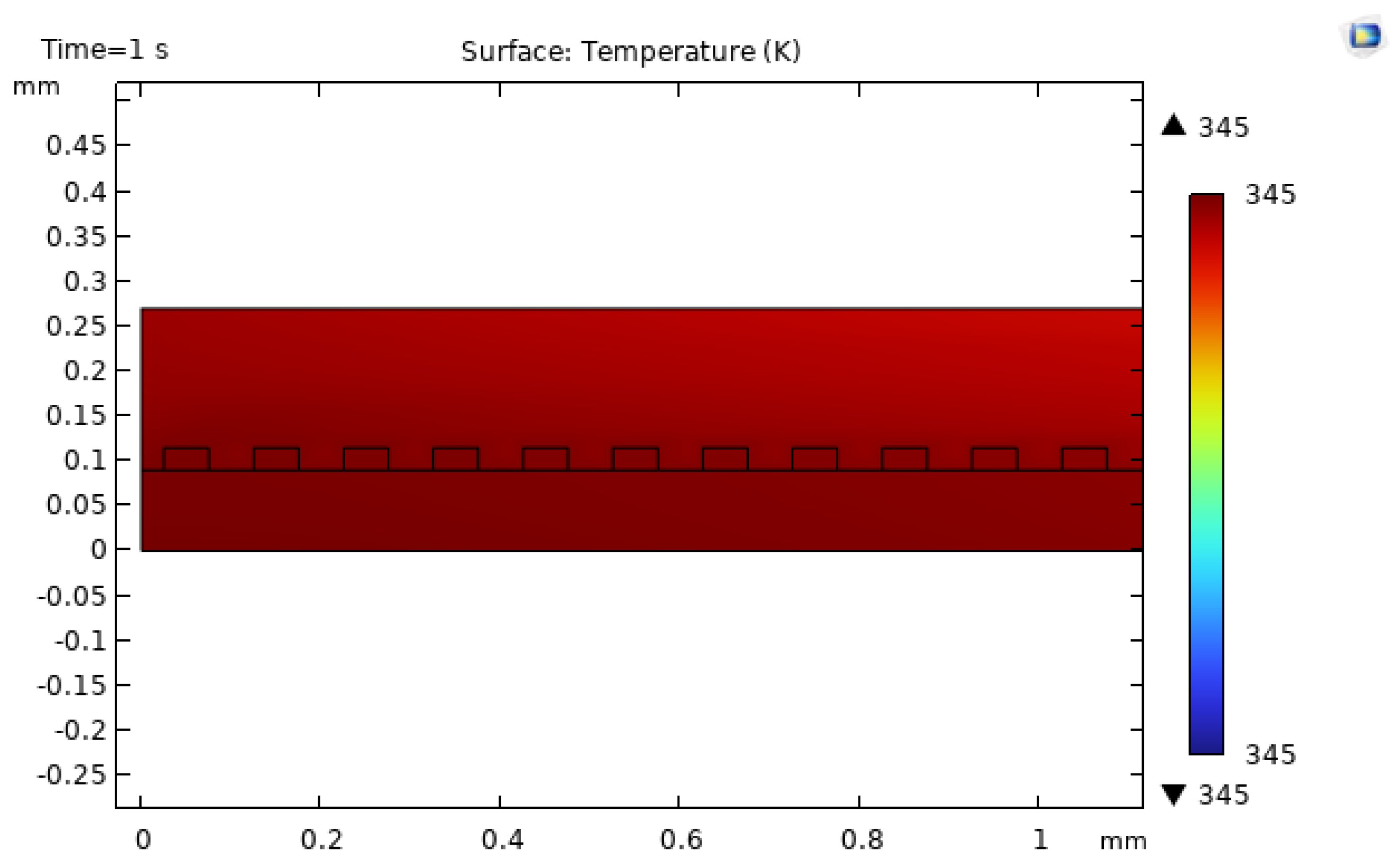
The rectangular roughness provides the weakest thermal enhancement, with maximum temperatures rising to around 345 K, only modestly better than (or in some regions comparable to) the baseline channel. This outcome suggests that the rectangular protrusions create regions of slow-moving fluid and thicker thermal boundary layers on their lee sides, which partially offset the benefits of increased surface area and localized acceleration [20,31,33,43].
3.4. Thermal–Hydraulic Performance Trade-Offs
A central goal in microchannel design is to maximize heat-transfer performance while limiting the associated increase in pressure drop and pumping power [2,21,39,44]. The present simulations illustrate this trade-off by demonstrating that all roughness shapes improve cooling compared with the smooth channel, but they also introduce additional flow resistance whose magnitude depends sensitively on geometry.
The triangular roughness case offers the most favorable balance among the configurations considered, combining strong boundary-layer disruption and mixing with a manageable pressure drop that remains within a practical range for microchannel pumping systems. The semi-circular case achieves good local enhancement near the entrance but allows the flow to adapt relatively quickly, leading to a situation where the channel behaves almost as if the effective wall location has shifted upward, with limited further gains downstream. The rectangular case, by contrast, incurs a comparatively high hydraulic penalty and exhibits large wake regions with elevated temperatures, making it less attractive from a system-level perspective.
These observations echo broader findings in the literature, where optimized roughness and vortex-generator designs often rely on streamlined or tapered shapes to maintain momentum while still thinning the thermal boundary layer [24,25,26,27]. Further work could quantify these trade-offs using performance metrics such as the thermal–hydraulic performance factor or entropy generation minimization, as commonly used in advanced microchannel design studies [21,31,32,44].
4. Conclusion
This study developed and applied a conjugate, laminar, nonisothermal COMSOL Multiphysics model to investigate how idealized surface-roughness geometries influence thermal–hydraulic performance in a copper microchannel heat sink cooled by water. A baseline smooth channel was first simulated to establish reference behavior and to verify that the model captured expected trends in pressure drop, velocity development, and wall temperature distribution under a uniform bottom heat flux. Three additional configurations—semi-circular, triangular, and rectangular roughness along the heated wall—were then evaluated under identical operating conditions to isolate the influence of roughness shape on flow and heat transfer.
The results show that all roughened channels reduce maximum fluid temperature relative to the smooth baseline, confirming that geometric perturbations can enhance convective cooling by disturbing laminar boundary layers and promoting mixing. Among the studied geometries, the triangular roughness provided the best thermal performance, achieving a minimum peak temperature of around 295 K with a moderate increase in pressure drop, while the rectangular roughness produced the weakest enhancement and the highest peak temperatures, on the order of 345 K. The semi-circular geometry delivered intermediate performance, with strong local acceleration near the entrance but less sustained disturbance farther downstream.
These findings highlight the importance of carefully tailoring roughness morphology, amplitude, and spacing when designing microchannel heat sinks that must either tolerate or exploit fabrication-induced surface textures [11,21,31,43]. Future work could extend the present two-dimensional analysis to fully three-dimensional geometries, explore a wider range of Reynolds numbers and heat fluxes, and incorporate temperature-dependent fluid properties, thereby providing a more comprehensive picture of how realistic surface roughness impacts microchannel cooling in next-generation electronic systems [22,29,30,45].
References
- D. G. Cahill et al., “Nanoscale thermal transport,” J. Appl. Phys., vol. 93, no. 2, pp. 793–818, 2003. [CrossRef]
- S. V. Garimella et al., “Thermal challenges in next-generation electronic systems,” IEEE Trans. Compon. Packag. Technol., vol. 31, no. 4, pp. 801–815, 2008. [CrossRef]
- M. Z. M. Hanafi, F. S. Ismail, and R. Rosli, “Radial plate fins heat sink model design and optimization,” in 2015 10th Asian Control Conference (ASCC), pp. 1–5, 2015.
- B. Li, Z. Cui, Q. Cao, and W. Shao, “Increasing efficiency of a finned heat sink using orthogonal analysis,” Energies, vol. 14, no. 3, p. 782, 2021.
- D. B. Tuckerman and R. F. W. Pease, “High-performance heat sinking for VLSI,” IEEE Electron Device Lett., vol. 2, no. 5, pp. 126–129, 1981.
- D. Sekar et al., “A 3D-IC technology with integrated microchannel cooling,” in 2008 International Interconnect Technology Conference, pp. 13–15, 2008.
- W. Zhang, F. Yang, R. Qiao, and D. Boroyevich, “Integrated microchannel cooling for power electronic modules,” Addit. Conf. Device Packag. HiTEC HiTEN CICMT, vol. 2016, pp. 122–129, 2016.
- N. Gilmore, V. Timchenko, and C. Menictas, “Microchannel cooling of concentrator photovoltaics: A review,” Renew. Sustain. Energy Rev., vol. 90, pp. 1041–1059, 2018.
- N. A. C. Sidik, M. N. A. W. Muhamad, W. M. A. A. Japar, and Z. A. Rasid, “An overview of passive techniques for heat transfer augmentation in microchannel heat sink,” Int. Commun. Heat Mass Transf., vol. 88, pp. 74–83, 2017.
- J. M. Acosta-Cuevas et al., “Surface roughness analysis of microchannels featuring microfluidic devices fabricated by three different materials and methods,” Coatings, vol. 13, no. 10, p. 1676, 2023.
- H. Lu et al., “Effects of surface roughness in microchannel with passive heat transfer enhancement structures,” Int. J. Heat Mass Transf., vol. 148, p. 119070, 2020.
- L. Pereira, T. Letcher, and G. Michna, “The effects of 3D printing parameters and surface roughness on convective heat transfer performance,” in ASME 2019 Heat Transfer Conference, 2019.
- T. M. F. Amin, M. Q. Huda, J. Tulip, and W. Jäger, “Sidewall roughness control in deep reactive ion etch process for micromachined Si devices,” in 2012 7th International Conference on Electrical and Computer Engineering, pp. 82–85, 2012.
- J. Du et al., “Optimization of embedded cooling for hotspots based on compound plate thermal spreading model,” Int. J. Heat Mass Transf., vol. 231, p. 125866, 2024.
- K. Goodson and Y. S. Ju, “Heat conduction in novel electronic films,” Annu. Rev. Mater. Sci., vol. 29, pp. 261–293, 1999.
- S. G. Kandlikar and W. J. Grande, “Evolution of microchannel flow passages—thermohydraulic performance and fabrication technology,” Heat Transf. Eng., vol. 24, no. 1, pp. 3–17, 2003.
- A. Yadav and Y. Singh, “A review on microchannel heat exchanger and the effects of various parameters,” AIP Conf. Proc., vol. 2521, p. 030016, 2023.
- A. Mukhopadhyay, S. Banerjee, and C. Gupta, “Fully developed hydrodynamic and thermal transport in combined pressure and electrokinetically driven flow in a microchannel with asymmetric boundary conditions,” Int. J. Heat Mass Transf., vol. 52, no. 7, pp. 2145–2154, 2009.
- P.-S. Lee, S. V. Garimella, and D. Liu, “Investigation of heat transfer in rectangular microchannels,” Int. J. Heat Mass Transf., vol. 48, no. 9, pp. 1688–1704, 2005.
- M. Ghobadi and Y. S. Muzychka, “A review of heat transfer and pressure drop correlations for laminar flow in curved circular ducts,” Heat Transf. Eng., vol. 37, no. 10, pp. 815–839, 2016.
- J. Zhang, Z. Zou, and C. Fu, “A review of the complex flow and heat transfer characteristics in microchannels,” Micromachines, vol. 14, no. 7, p. 1451, 2023.
- COMSOL AB, “CFD simulation of micro-channel heat sink used for cooling applications,” Application Library, accessed Dec. 2025.
- M. B. Turgay and A. G. Yazıcıoğlu, “Numerical simulation of fluid flow and heat transfer in a trapezoidal microchannel with COMSOL multiphysics: A case study,” Numer. Heat Transf. Part A, vol. 73, no. 5, pp. 332–346, 2018.
- J. Zhou, M. Hatami, D. Song, and D. Jing, “Design of microchannel heat sink with wavy channel and its time-efficient optimization with combined RSM and FVM methods,” Int. J. Heat Mass Transf., vol. 103, pp. 715–724, 2016.
- A. Gönül, “Enhancement of heat transfer characteristics in wavy microchannel heat sinks with streamlined micropins within convergent–divergent flow passages,” Appl. Therm. Eng., vol. 258, p. 124574, 2025.
- D. K. Raj and A. Datta, “Numerical analysis of microchannel heat sink performance using delta vortex generator,” Phys. Fluids, vol. 36, no. 4, p. 043615, 2024.
- E. Salamatbakhsh and Ö. Bayer, “Hydrothermal performance of a wavy minichannel heatsink with longitudinal vortex generators,” SSRN 4654996, 2023.
- H. Wu and S. Zhang, “Numerical study on the fluid flow and heat transfer characteristics of Al2O3–water nanofluids in microchannels of different aspect ratio,” Micromachines, vol. 12, no. 8, p. 868, 2021.
- M. Kalteh et al., “Experimental and numerical investigation of nanofluid forced convection inside a wide microchannel heat sink,” Appl. Therm. Eng., vol. 36, pp. 260–268, 2012.
- X. Zeng, H. Yu, T. He, and N. Mao, “A numerical study on heat transfer characteristics of a novel rectangular grooved microchannel with Al2O3/water nanofluids,” Energies, vol. 15, no. 19, p. 7187, 2022.
- H. A. Kose, A. Yildizeli, and S. Cadirci, “Parametric study and optimization of microchannel heat sinks with various shapes,” Appl. Therm. Eng., vol. 211, p. 118368, 2022.
- Y. Xiong et al., “Multi-objective designs of microchannel heat sink for multilayer composite chip heat transfer systems using topology optimization,” Appl. Therm. Eng., vol. 279, p. 127876, 2025.
- P. Rosa, T. G. Karayiannis, and M. W. Collins, “Single-phase heat transfer in microchannels: The importance of scaling effects,” Appl. Therm. Eng., vol. 29, no. 17, pp. 3447–3468, 2009.
- M. A. Hussain, S. Yesudasan, and S. Chacko, “Nanofluids for solar thermal collection and energy conversion,” Preprints, 2020, preprint article.
- S. Yesudasan, “The critical diameter for continuous evaporation is between 3 and 4 nm for hydrophilic nanopores,” Langmuir, vol. 38, no. 21, pp. 6550–6560, 2022.
- S. Yesudasan, “Thermal dynamics of heat pipes with sub-critical nanopores,” arXiv:2406.xxxxx [physics.flu-dyn], 2024, arXiv preprint. arXiv:2406.xxxxx.
- M. M. Mohammed and S. Yesudasan, “Molecular dynamics study on the properties of liquid water in confined nanopores: Structural, transport, and thermodynamic insights,” in Proc. ASEE Northeast Section Conf., 2025, pp. 1–7.
- V. Hotchandani, B. Mathew, S. Yesudasan, and S. Chacko, “Thermo-hydraulic characteristics of novel MEMS heat sink,” Microsyst. Technol., vol. 27, no. 1, pp. 145–157, 2021.
- S. G. Kandlikar et al., “Heat transfer in microchannels—2012 status and research needs,” J. Heat Transf., vol. 135, no. 091001, 2013.
- A. Jain and G. Krishnan, “Thermal spreading in a multilayer geometry with convective cooling along the side wall of each layer,” Int. J. Heat Mass Transf., vol. 236, p. 126253, 2025.
- J. Li and G. P. Peterson, “3-dimensional numerical optimization of silicon-based high performance parallel microchannel heat sink with liquid flow,” Int. J. Heat Mass Transf., vol. 50, no. 15, pp. 2895–2904, 2007.
- M. M. Rahman et al., “Comparison of 2D and 3D modelling applied to single phase flow of nanofluid through corrugated channels,” Computational Fluid Dynamics Letters, vol. 14, no. 1, pp. 128–139, 2022.
- Y. Gong and G. Zhou, “Numerical simulation of structured surface roughness effects on flow boiling characteristics in microchannel,” Chem. Eng. Process., vol. 216, p. 110439, 2025.
- S. Li et al., “A state-of-the-art overview on the developing trend of heat transfer enhancement by single-phase flow at micro scale,” Int. J. Heat Mass Transf., vol. 143, p. 118476, 2019.
- J. Dix and A. Jokar, “Fluid and thermal analysis of a microchannel electronics cooler using computational fluid dynamics,” Appl. Therm. Eng., vol. 30, no. 8, pp. 948–961, 2010.
- L. Zhao et al., “Thermal modeling for processors and systems-on-chip,” in Thermal and Power Management of Integrated Circuits, pp. 1–26, 2015.
- R. Kakac, R. Shah, and W. Aung, Laminar Flow Forced Convection in Ducts. Academic Press, 1987.
- M. Azmi and N. Hafiz, “CFD analysis of single-phase nanofluid flow through corrugated channels: 2D vs 3D,” Int. Commun. Heat Mass Transf., vol. 142, p. 106754, 2023.
Figure 1.
Three-dimensional models of the four microchannel configurations: smooth (baseline), semi-circular roughness, triangular roughness, and rectangular roughness.
Figure 1.
Three-dimensional models of the four microchannel configurations: smooth (baseline), semi-circular roughness, triangular roughness, and rectangular roughness.
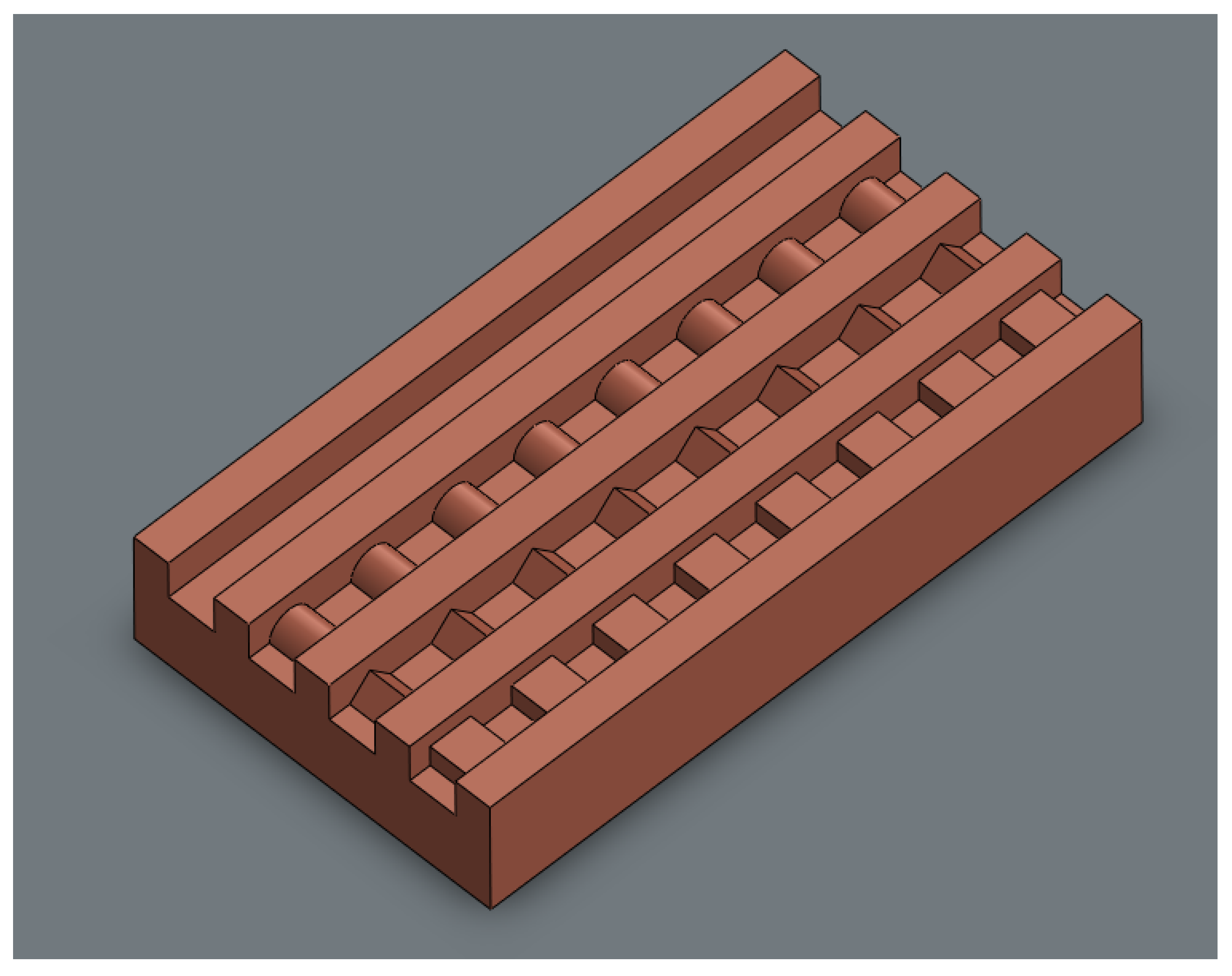
Figure 2.
Two-dimensional geometry of the baseline smooth microchannel, showing channel height, width, and copper substrate.
Figure 2.
Two-dimensional geometry of the baseline smooth microchannel, showing channel height, width, and copper substrate.
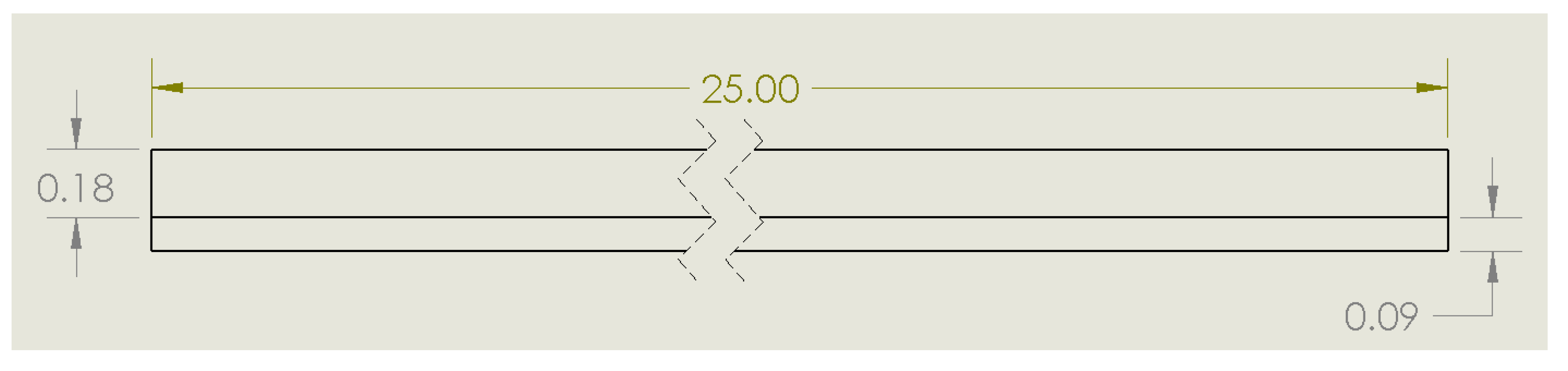
Figure 3.
Two-dimensional geometry of the microchannel with semi-circular roughness elements along the bottom wall.
Figure 3.
Two-dimensional geometry of the microchannel with semi-circular roughness elements along the bottom wall.
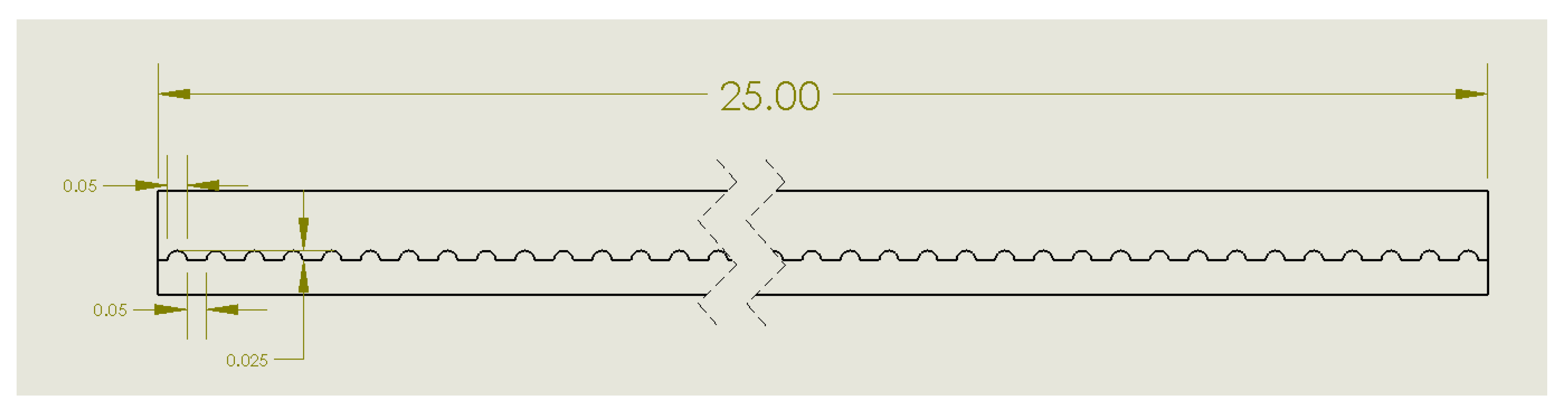
Figure 4.
Two-dimensional geometry of the microchannel with triangular roughness elements along the bottom wall.
Figure 4.
Two-dimensional geometry of the microchannel with triangular roughness elements along the bottom wall.
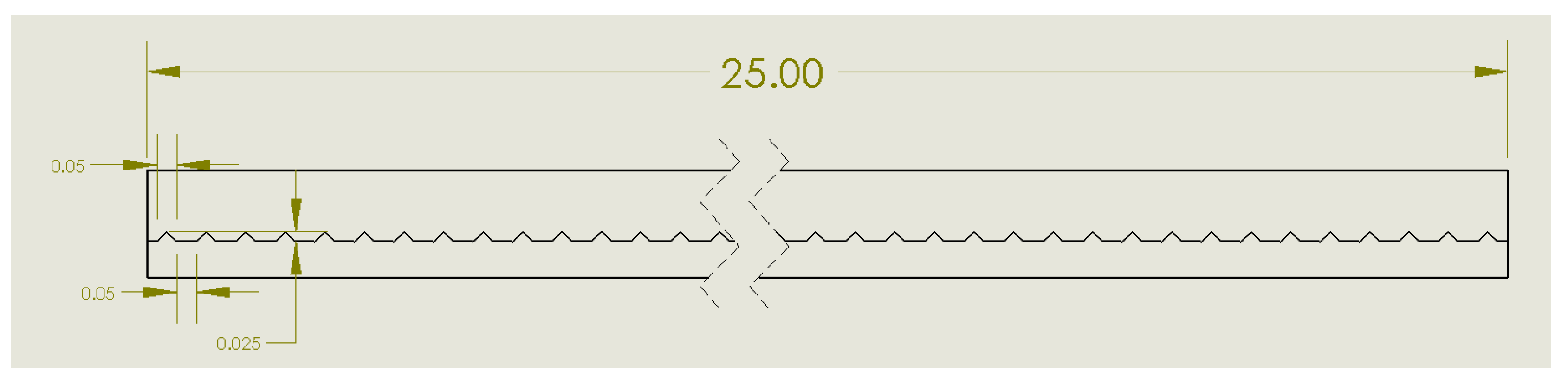
Figure 5.
Two-dimensional geometry of the microchannel with rectangular roughness elements along the bottom wall.
Figure 5.
Two-dimensional geometry of the microchannel with rectangular roughness elements along the bottom wall.
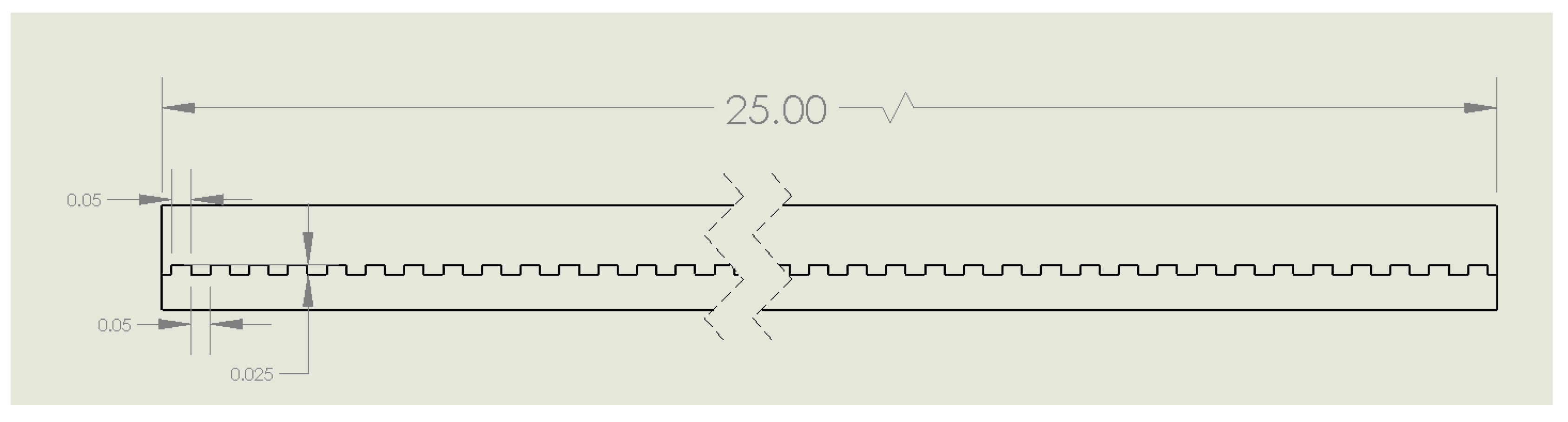
Figure 6.
Fluid (water) domain selection in COMSOL for the two-dimensional microchannel model.
Figure 7.
Copper substrate domain selection for the baseline microchannel configuration.
Figure 8.
Copper domain selection including the additional roughness geometries used in the roughened-channel simulations.
Figure 8.
Copper domain selection including the additional roughness geometries used in the roughened-channel simulations.
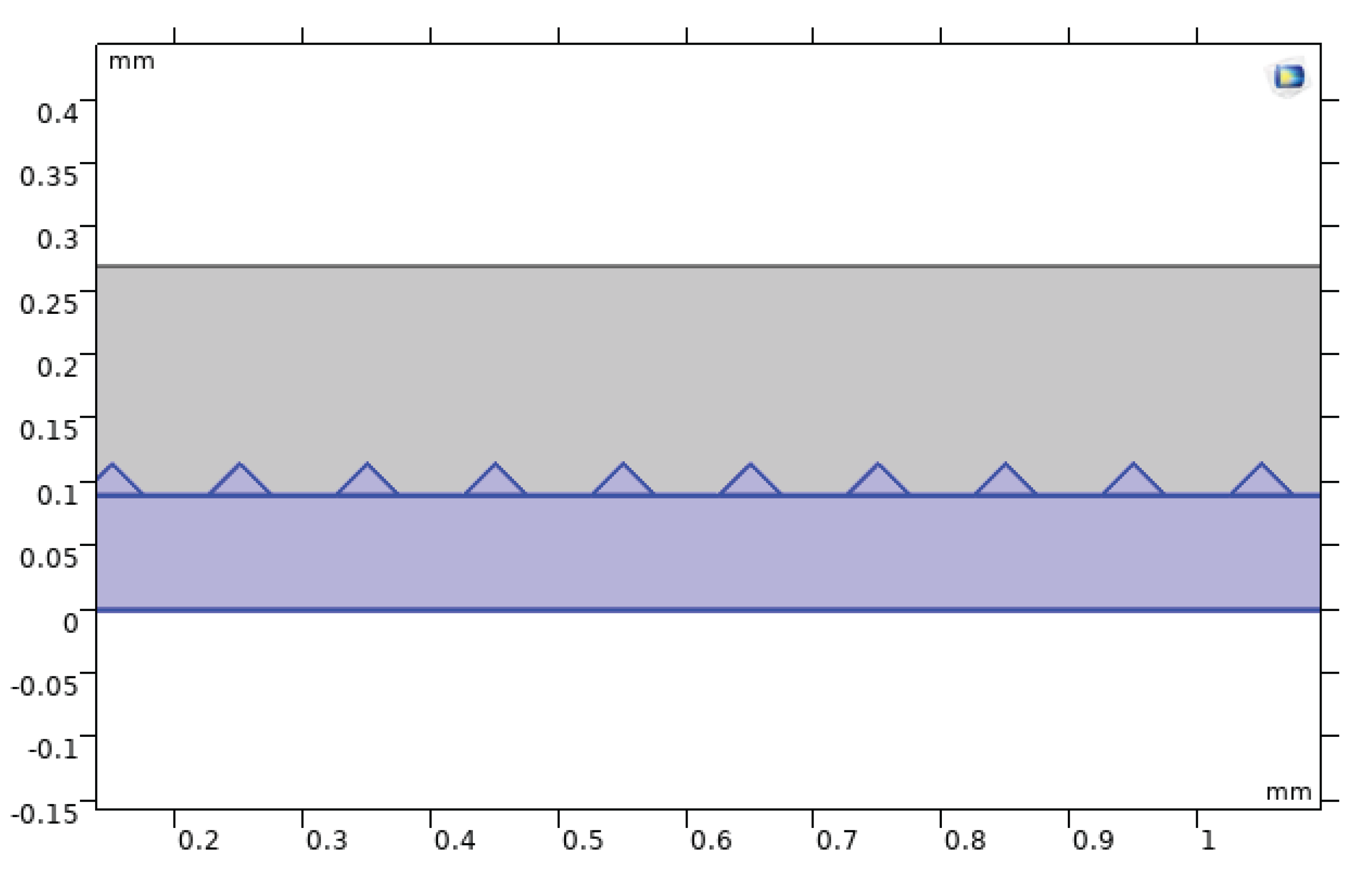
Figure 9.
Finite-element mesh for the baseline smooth microchannel.
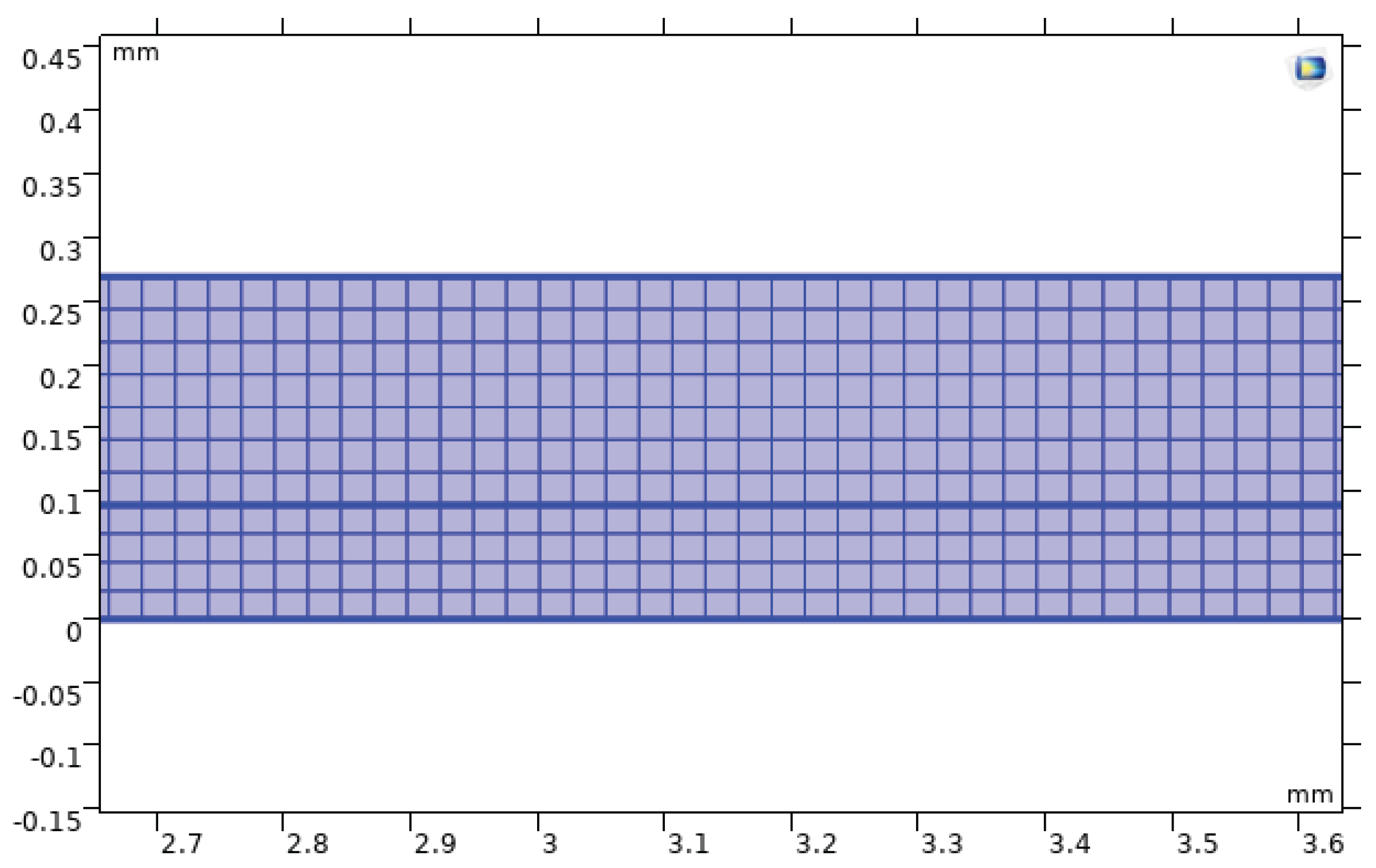
Figure 10.
Finite-element mesh for the microchannel with semi-circular roughness elements.
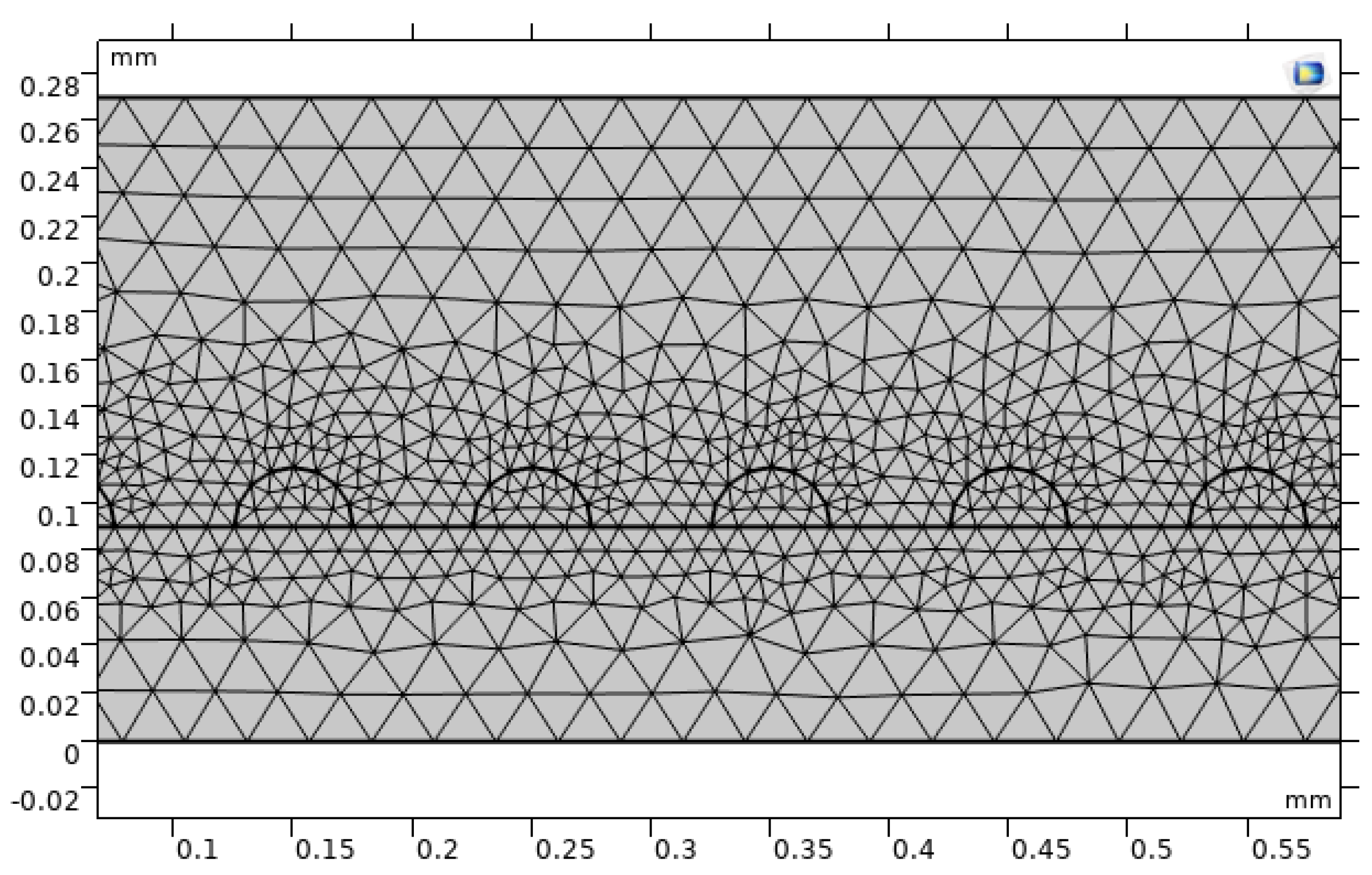
Figure 11.
Boundary selection for the applied uniform heat flux at the bottom copper surface.
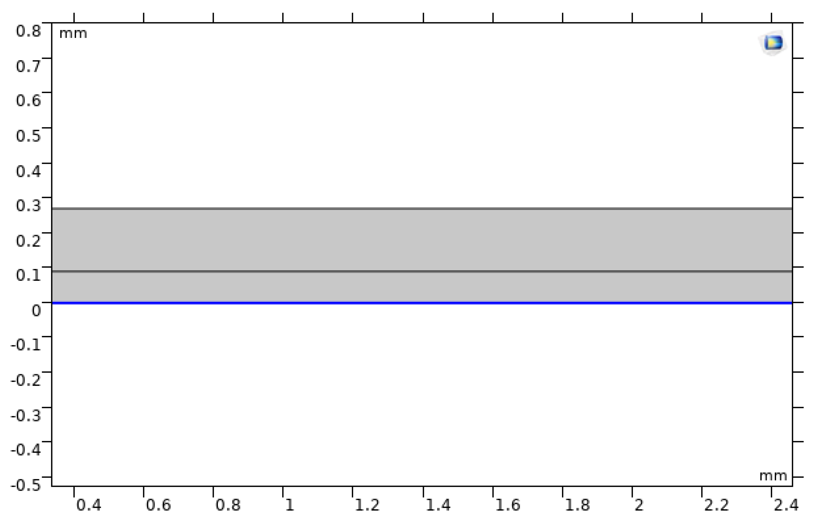
Figure 12.
Boundary selection and definition of the inlet velocity condition for the microchannel.
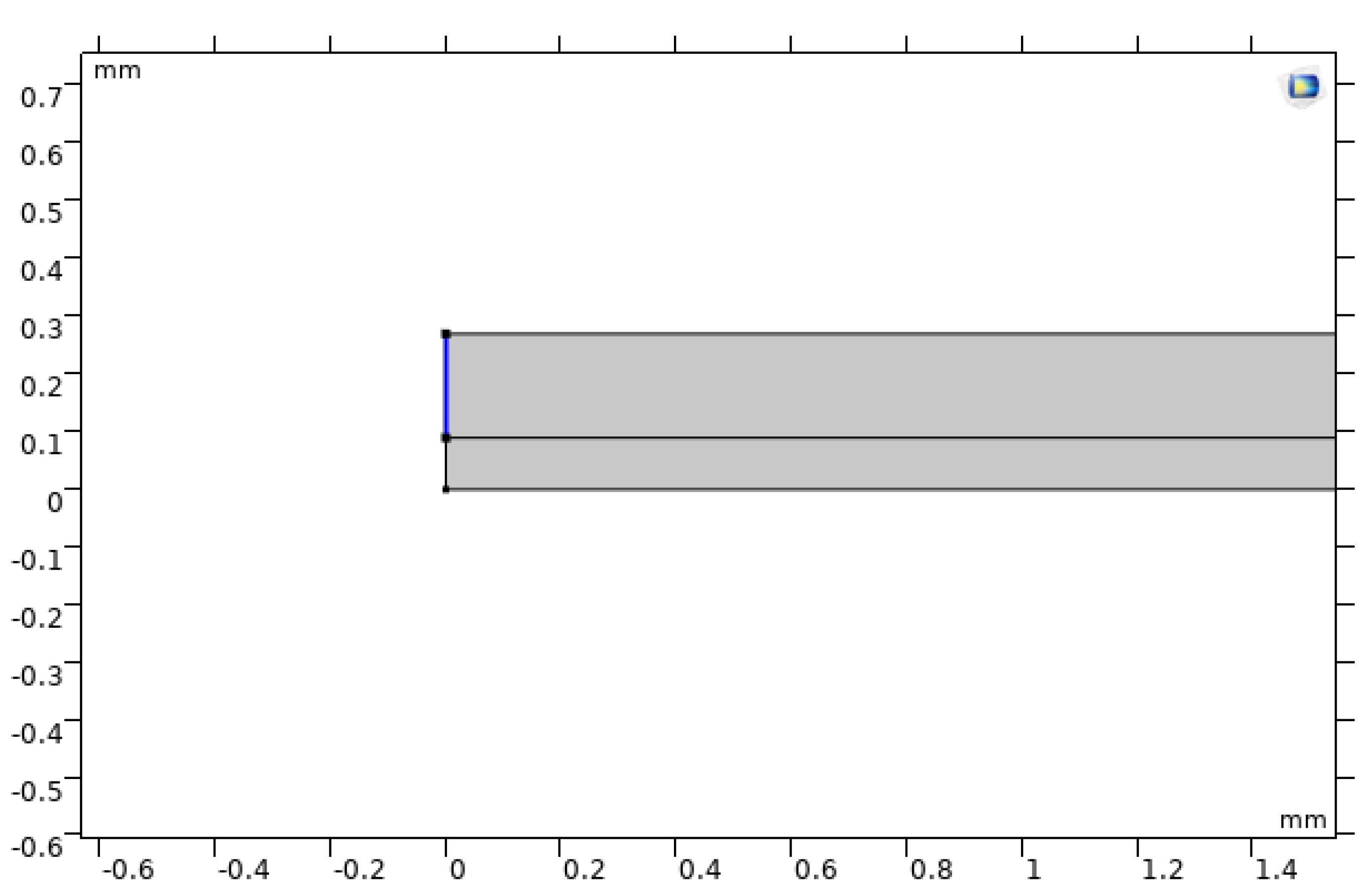
Figure 13.
Boundary selection and definition of the outlet pressure condition for the microchannel.
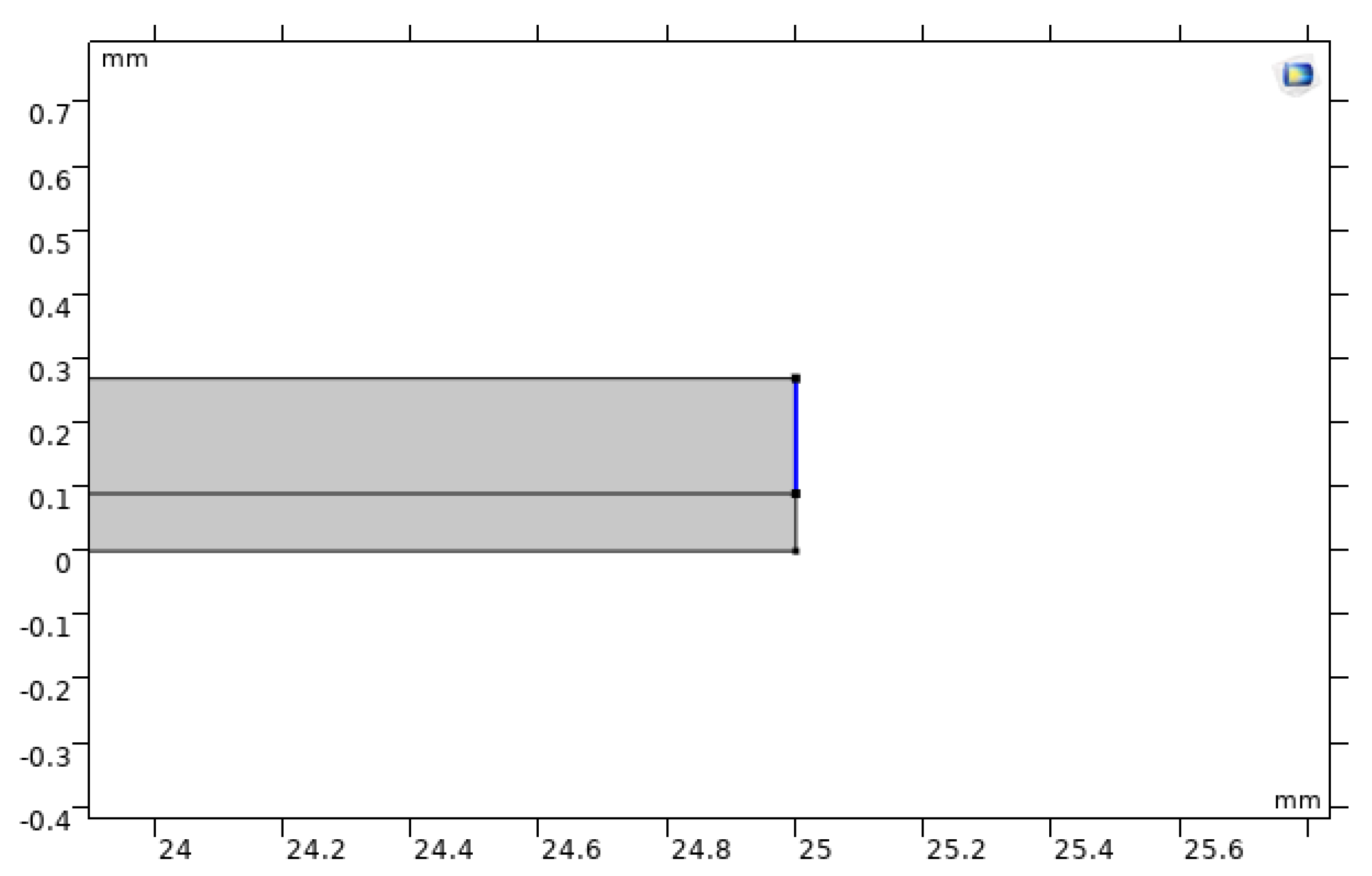
Figure 14.
Velocity field in the baseline smooth microchannel, showing entrance-region development and acceleration.
Figure 14.
Velocity field in the baseline smooth microchannel, showing entrance-region development and acceleration.
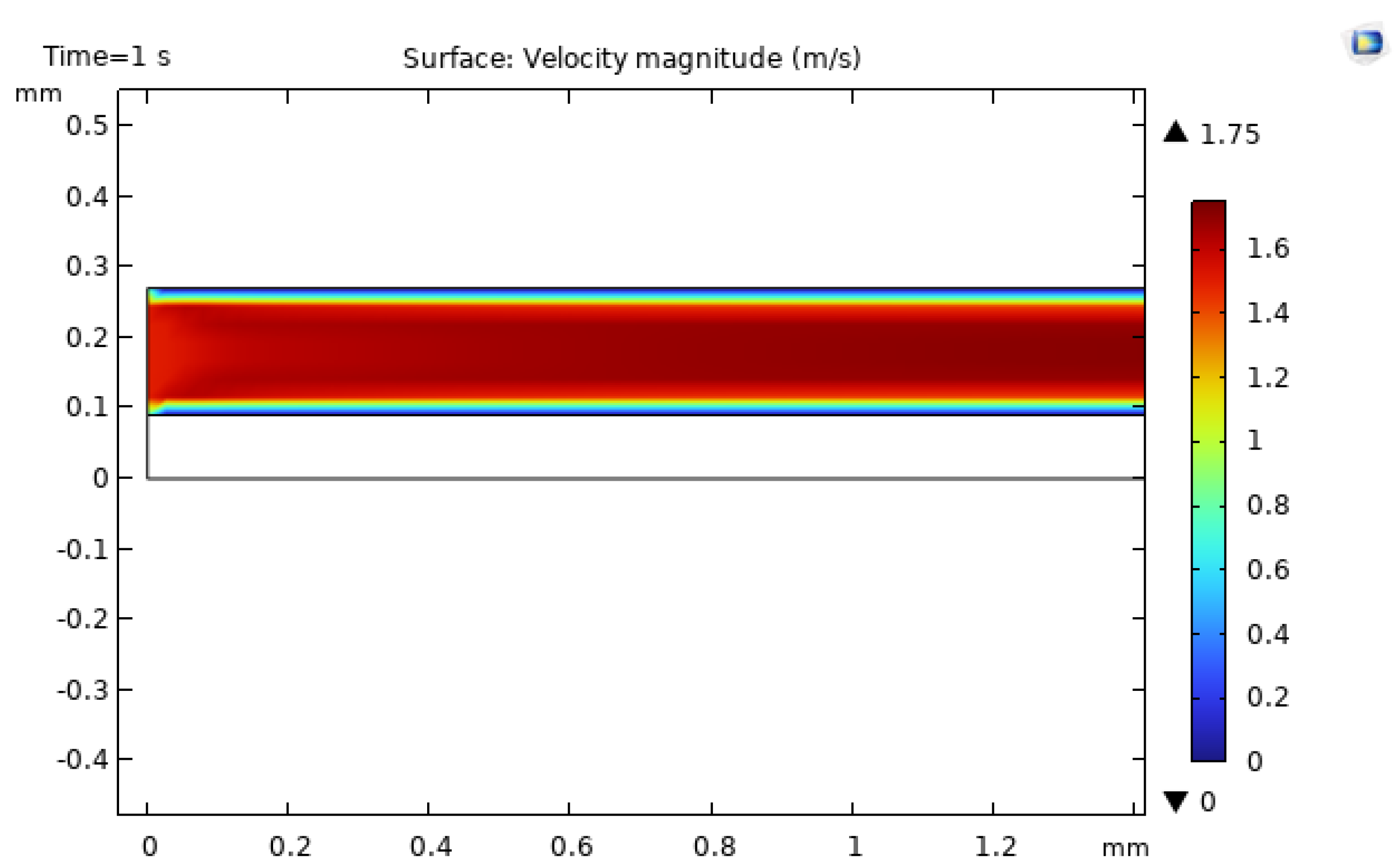
Figure 15.
Temperature distribution in the baseline smooth microchannel, illustrating the gradual temperature rise along the heated wall.
Figure 15.
Temperature distribution in the baseline smooth microchannel, illustrating the gradual temperature rise along the heated wall.
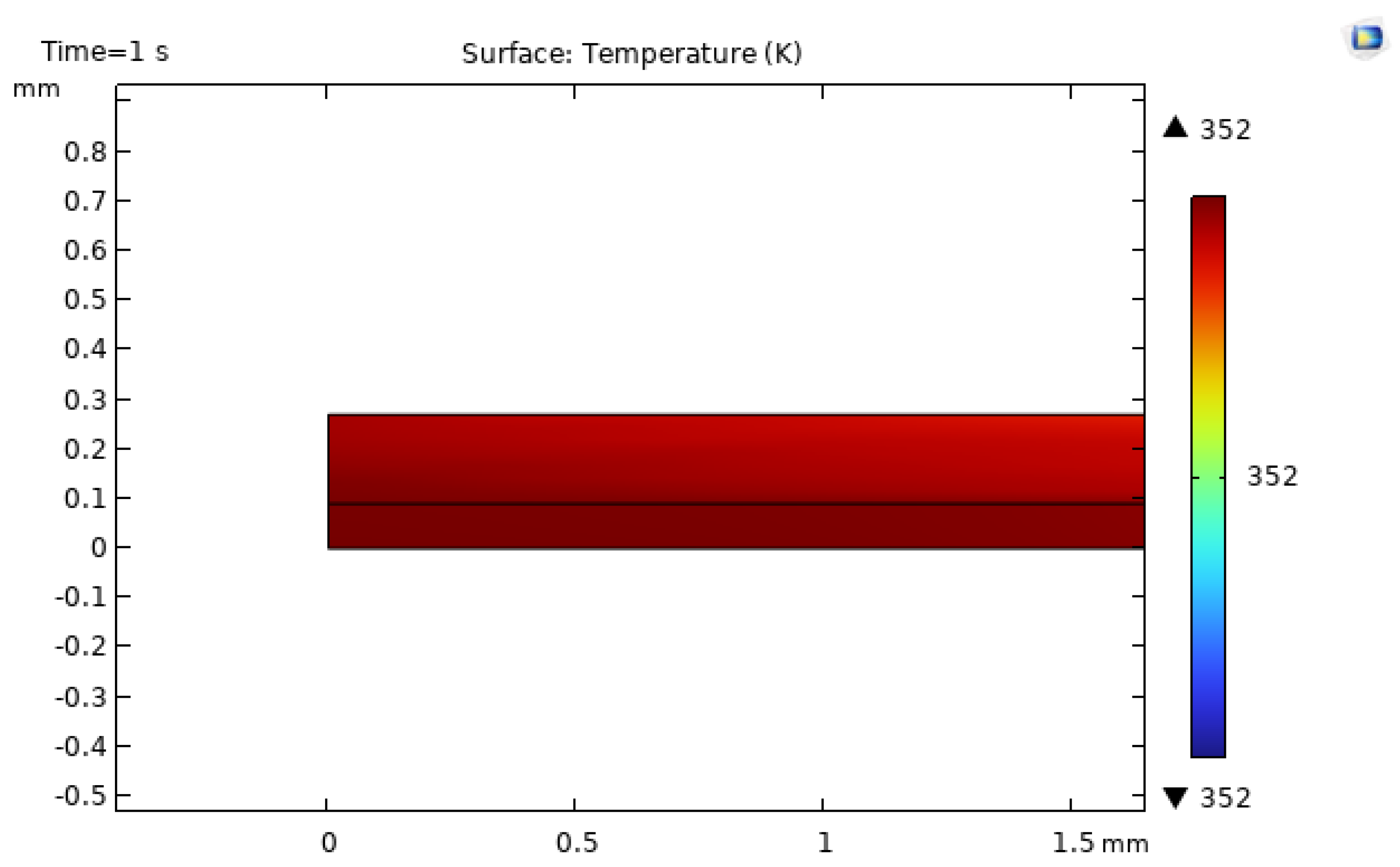
Figure 16.
Velocity field in the microchannel with semi-circular roughness elements, highlighting local acceleration around curved features.
Figure 16.
Velocity field in the microchannel with semi-circular roughness elements, highlighting local acceleration around curved features.
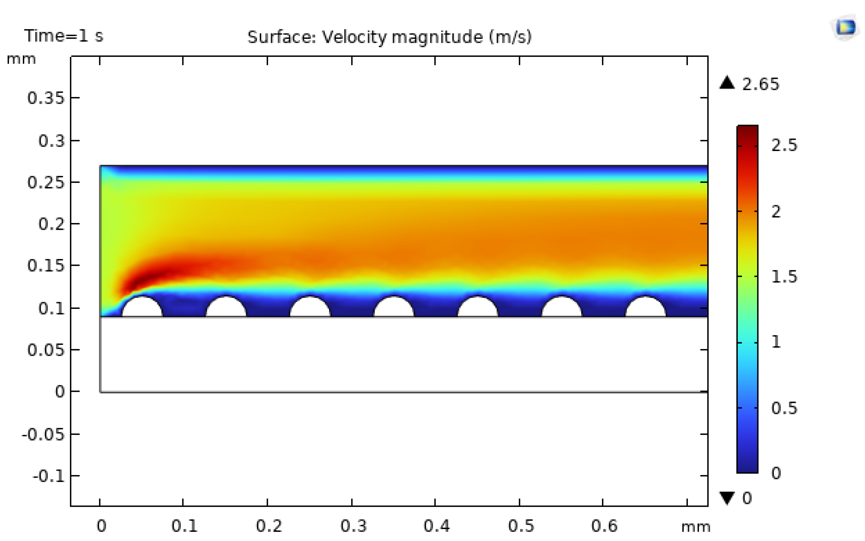
Figure 17.
Velocity field in the microchannel with triangular roughness elements, showing strong local accelerations and wake regions downstream of each feature.
Figure 17.
Velocity field in the microchannel with triangular roughness elements, showing strong local accelerations and wake regions downstream of each feature.
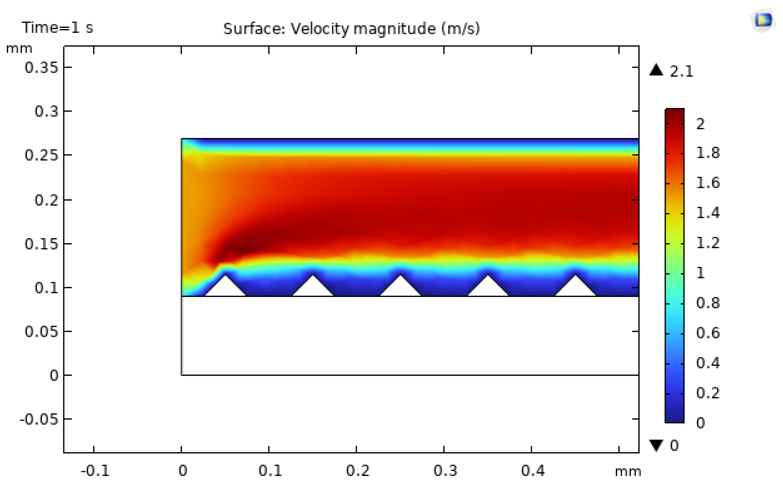
Figure 18.
Velocity field in the microchannel with rectangular roughness elements, indicating flow separation and recirculation behind protrusions.
Figure 18.
Velocity field in the microchannel with rectangular roughness elements, indicating flow separation and recirculation behind protrusions.
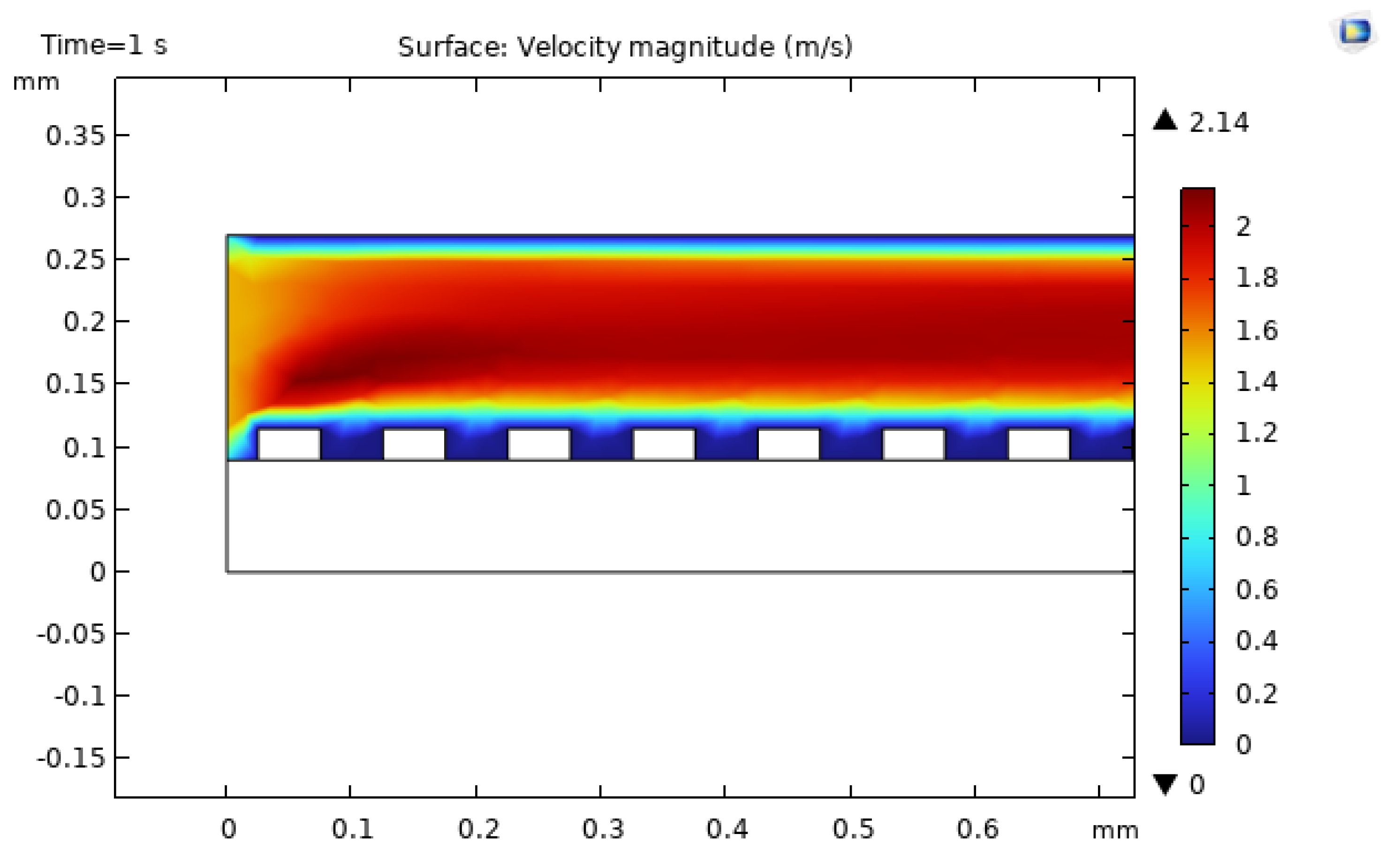
Figure 19.
Temperature distribution in the microchannel with semi-circular roughness elements, showing reduced peak temperatures compared with the smooth baseline.
Figure 19.
Temperature distribution in the microchannel with semi-circular roughness elements, showing reduced peak temperatures compared with the smooth baseline.
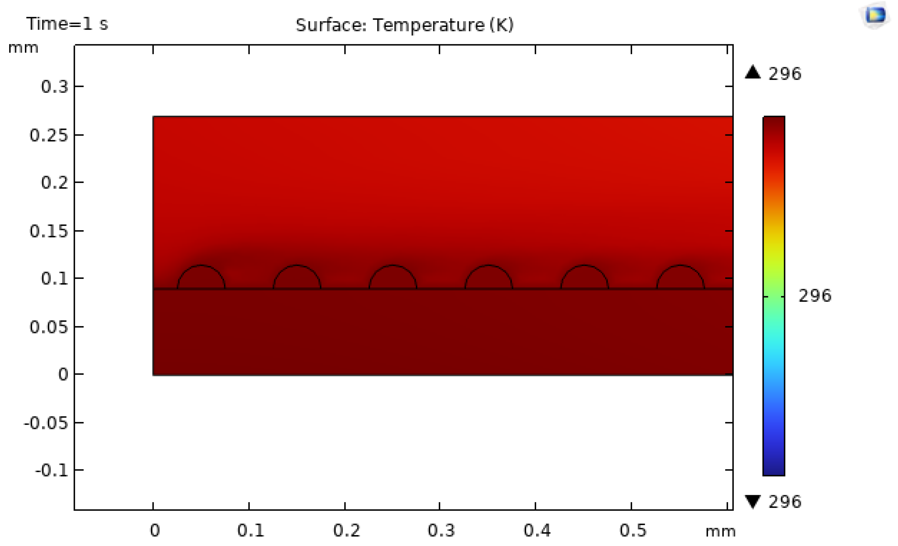
Figure 20.
Temperature distribution in the microchannel with triangular roughness elements, exhibiting the lowest maximum temperature among all studied geometries.
Figure 20.
Temperature distribution in the microchannel with triangular roughness elements, exhibiting the lowest maximum temperature among all studied geometries.
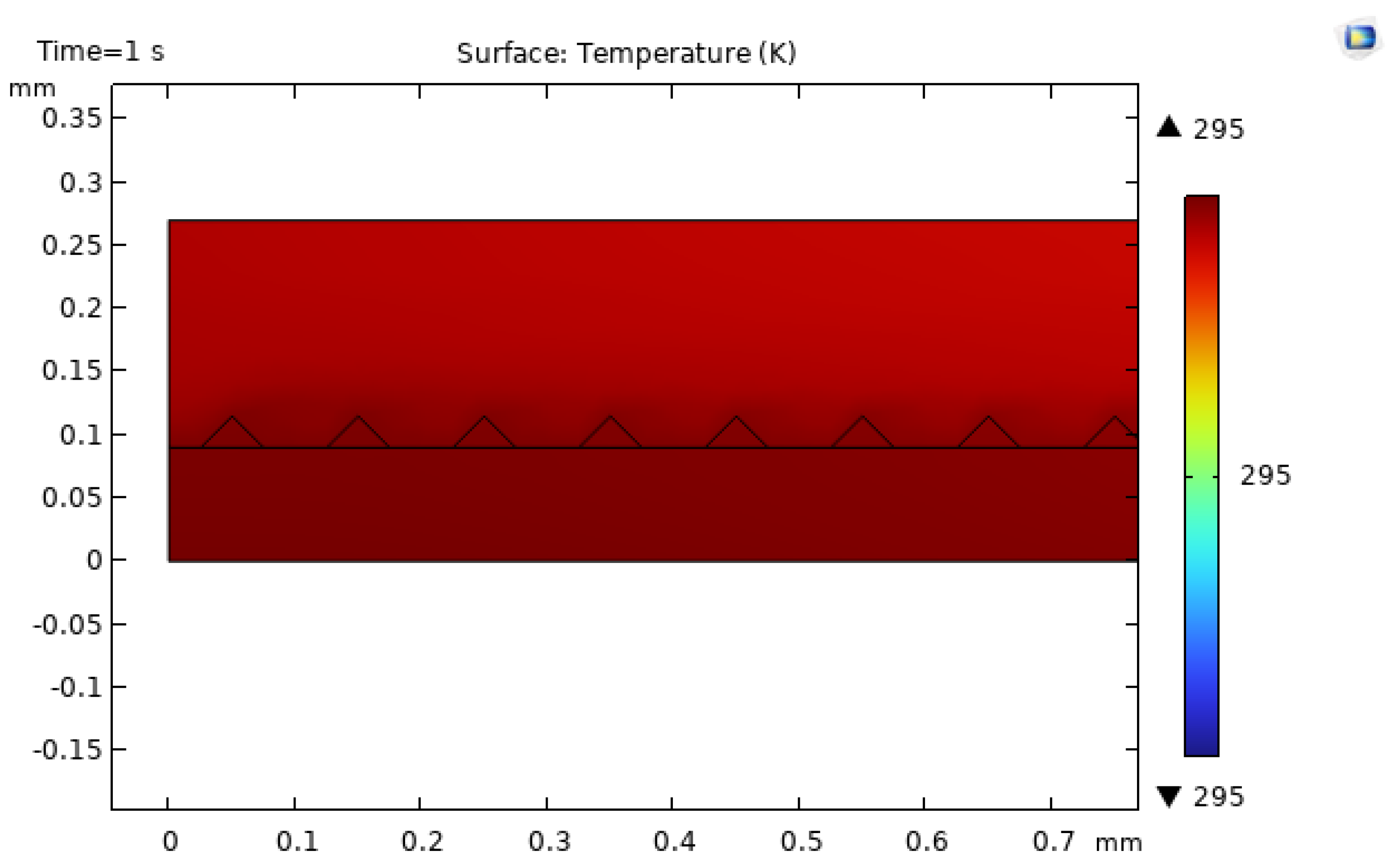
Figure 21.
Temperature distribution in the microchannel with rectangular roughness elements, showing weaker thermal enhancement and higher peak temperatures.
Figure 21.
Temperature distribution in the microchannel with rectangular roughness elements, showing weaker thermal enhancement and higher peak temperatures.
Disclaimer/Publisher’s Note: The statements, opinions and data contained in all publications are solely those of the individual author(s) and contributor(s) and not of MDPI and/or the editor(s). MDPI and/or the editor(s) disclaim responsibility for any injury to people or property resulting from any ideas, methods, instructions or products referred to in the content. |
© 2025 by the authors. Licensee MDPI, Basel, Switzerland. This article is an open access article distributed under the terms and conditions of the Creative Commons Attribution (CC BY) license (http://creativecommons.org/licenses/by/4.0/).
Copyright: This open access article is published under a Creative Commons CC BY 4.0 license, which permit the free download, distribution, and reuse, provided that the author and preprint are cited in any reuse.


