Submitted:
28 December 2025
Posted:
30 December 2025
You are already at the latest version
Abstract
Electronic devices and compact energy systems are becoming smaller and more powerful, which creates serious challenges for thermal management. Large amounts of heat must be removed from very small areas without exceeding safe operating temperatures. Microchannel heat exchangers (MCHXs) can address this problem because they provide a high surface-to-volume ratio and strong convective heat transfer in a compact volume. In this work, a three-dimensional copper microchannel heat sink is developed and analyzed using COMSOL Multiphysics 6.2 by coupling the Laminar Flow and Heat Transfer in Solids and Fluids interfaces. The baseline geometry consists of ten parallel rectangular microchannels with a width of 1mm and a fin thickness of 0.5mm. The heat sink is subjected to a uniform heat flux of 5x10⁴ W/m2 and is cooled by water entering at 293.15 K. The study explores how geometric parameters such as channel width, fin thickness, and channel count influence both thermal performance (maximum temperature, thermal resistance, and Nusselt number) and hydraulic performance (pressure drop and pumping power). The results show that narrower channels and thinner fins can significantly reduce maximum temperature and improve temperature uniformity, but they also increase pressure drop and required pumping power. The optimized configuration achieves a good balance between low thermal resistance and moderate pressure drop. The modeling approach provides a simple, repeatable procedure that can be extended to more complex geometries, alternative coolants, and optimization frameworks.
Keywords:
microchannel heat exchanger
; COMSOL
; laminar flow
; conjugate heat transfer
; pressure drop
; optimization
1. Introduction
Electronic components such as processors, power electronics, and laser diodes generate large amounts of heat in increasingly small volumes. If this heat is not removed effectively, device temperatures will rise, which can reduce efficiency, shorten lifetime, and even cause catastrophic failure [4,5]. Traditional air-cooled finned heat sinks are often not sufficient for the highest power densities, especially when there is limited space or when strict temperature limits must be maintained.
Microchannel heat exchangers (MCHXs) offer a promising way to improve thermal management in such applications. When the hydraulic diameter of a channel is reduced to the microscale, the surface-area-to-volume ratio increases sharply. This increase allows more heat to be transferred per unit volume, and the thermal boundary layer remains relatively thin, which supports higher local heat transfer coefficients [1]. At the same time, the small size of microchannels makes some physical effects more important, such as axial heat conduction in the solid, viscous resistance, and transitions between laminar and turbulent flow at lower Reynolds numbers compared with larger channels [4].
A major challenge in microchannel design is that improvements in heat transfer usually come at the cost of higher pressure drop. Narrowing channels, adding internal structures, or introducing sharp turns and complex manifolds can all enhance mixing and heat transfer, but they also increase frictional losses and thus the pumping power required to drive the flow [3,6]. If the pressure drop becomes too large, the required pump may be bulky, noisy, or inefficient, offsetting the benefits gained on the thermal side. For this reason, modern design studies focus on both thermal and hydraulic performance simultaneously, rather than looking at one in isolation [2,26].
Several recent review papers summarize the rapid progress in microchannel heat sink technology, covering topics such as new channel geometries, manifold and header designs, advanced working fluids, and optimization strategies [26,27,28,29,30]. These reviews highlight that there is no single universally optimal microchannel configuration. Instead, effective design requires balancing conflicting goals such as high heat transfer, low pressure drop, manufacturability, and robustness to fouling or clogging.
In this study, a copper microchannel heat sink is modeled in COMSOL Multiphysics to investigate this balance in a controlled and transparent way. A relatively simple geometry with straight rectangular channels is chosen to keep the configuration realistic and easy to manufacture. The main questions addressed are: (1) How do channel width, fin thickness, and the number of channels affect maximum temperature, thermal resistance, and Nusselt number? and (2) How do these same parameters influence pressure drop and pumping power? By answering these questions, the work provides a clear, step-by-step procedure for designing microchannel heat sinks that minimize pressure drop while maximizing heat transfer within practical constraints.
2. Literature Review
Microchannel heat sinks have been widely studied for cooling integrated circuits, batteries, laser diodes, and other high heat flux devices. Properly designed systems can dissipate several hundred to around a thousand while maintaining acceptable temperature levels [7]. The high surface-area-to-volume ratio of microchannels enhances convective heat transfer, but it also makes the flow and temperature fields highly sensitive to geometric details.
A number of studies have examined how basic geometric parameters such as channel width, height, and aspect ratio affect performance. Ege et al. found that reducing channel width decreases thermal resistance but increases flow friction and pressure drop [8]. Kumar showed that trapezoidal cross-sections with grooves can enhance mixing and increase the Nusselt number compared with rectangular channels, at the cost of a more complex geometry [9]. These examples demonstrate that channel shape strongly influences both heat transfer and hydraulic behavior.
More recent work has focused on deliberately modified geometries to further boost performance. Wavy channels, for example, have been used to periodically disturb the thermal boundary layer and generate secondary flows, leading to higher local and average Nusselt numbers [10,31,32]. Cross-ribbed and roughened microchannels can further enhance mixing and turbulence (or quasi-turbulent structures in laminar regimes), which tends to reduce maximum temperatures and make the temperature distribution more uniform [33,34,36]. Biomimetic or bionic designs inspired by branching rivers, leaf veins, or vascular networks aim to improve flow distribution and thermal performance by mimicking efficient natural structures [28,35].
Flow maldistribution in parallel microchannel systems is another critical issue. Even when all channels share the same cross-section, they may not carry equal flow rates if the inlet and outlet manifolds are not well designed. Manoj Siva et al. showed that maldistribution can greatly reduce the effectiveness of microchannel cooling in integrated device packages [11]. Lin et al. demonstrated that tapered manifolds and carefully shaped inlet structures can reduce maldistribution and improve temperature uniformity by more than 10% in some configurations [12]. Several recent studies have reported complementary insights into thermal transport and evaporation phenomena in micro- and nanoscale systems using both numerical and molecular approaches [42,43,44,45,46]. Building on such efforts, several studies have applied multi-objective optimization, topology optimization, and adjoint-based design to manifold microchannel heat sinks. These advanced techniques search for channel and header shapes that minimize temperature nonuniformity and pressure drop simultaneously [37,38,39,40,41].
The choice of working fluid adds another layer of complexity. Nanofluids and hybrid nanofluids, which contain suspended nanoparticles such as metal oxides or hybrid mixtures, can significantly increase effective thermal conductivity and convective heat transfer [16,29]. Several studies since 2020 have reported 20–50% increases in heat transfer coefficients by using nanofluids in microchannel heat sinks, but also substantial increases in viscosity and pressure drop [30,47,48,49]. Other works have examined porous fillings, internal fins, and hybrid microchannel–heat pipe or jet-impingement configurations to further improve performance at manageable pumping costs [17,18,50,51,52].
Several recent reviews tie these developments together and emphasize the need for integrated, system-level evaluation of microchannel designs [26,27,28]. They recommend that new geometries be assessed not only in terms of heat transfer enhancements but also in terms of pressure drop, manufacturability, fouling resistance, and long-term stability. The present work follows this guidance by focusing on a realistic, manufacturable geometry and reporting both thermal and hydraulic metrics for each configuration studied.
3. Design Methodology
The microchannel heat sink considered in this study is a copper block with multiple straight channels carrying water as the coolant. The design is intentionally simple, using rectangular channels arranged in parallel, to keep the geometry realistic and to match many existing experimental and numerical benchmarks. The main aim is to understand how channel width, fin thickness, and the number of channels affect both temperature and pressure drop under fixed operating conditions.
The model is implemented in COMSOL Multiphysics 6.2 using two physics interfaces: Laminar Flow (spf) for the coolant and Heat Transfer in Solids and Fluids (ht) for the combined solid–fluid domain. This approach allows the simulation to resolve velocity and pressure in the fluid, as well as temperature in both the copper and water, with full conjugate heat transfer [22,23]. The overall modeling steps can be summarized as:
- Define the geometry of the copper block, internal channels, and manifolds.
- Assign material properties to the copper and water domains.
- Specify boundary and initial conditions for velocity, pressure, and temperature.
- Generate an appropriate mesh, refined near solid–fluid interfaces.
- Solve the steady-state coupled fluid flow and heat transfer problem.
- Extract key performance metrics such as maximum temperature, thermal resistance, Nusselt number, pressure drop, and pumping power.
This workflow is similar to that used in several recent numerical studies on microchannel heat sinks and allows results to be compared or extended using alternative geometries and fluids [13,20,21,37,38].
Design Requirements
All simulations are performed using COMSOL Multiphysics 6.2. The model is intended to represent a compact heat sink suitable for mounting on high-power electronic packages. The design should satisfy three main requirements:
- Provide sufficient heat transfer capacity to keep maximum temperature within safe limits.
- Maintain a moderate pressure drop to avoid excessive pumping power.
- Use a geometry that is realistic to fabricate with current manufacturing methods for copper and typical microfabrication or machining processes.
Geometry
The copper heat sink has overall dimensions of . Inside this block, ten straight microchannels are cut along the flow direction. Each channel is wide and high. The solid fins between adjacent channels are thick. This arrangement provides a compromise between three needs: a large heat transfer surface area, enough mechanical strength of the copper fins, and sufficient flow area to keep the pressure drop at a manageable level [14,20].
Figure 1 shows the top view of the microchannel heat sink, including the inlet and outlet manifolds and the surrounding solid walls. The ten channels run parallel to each other along the length of the device, and short inlet and outlet extensions help guide the flow into and out of the channels. The outer walls are thicker than the internal fins to provide mechanical strength and to allow easy mounting onto a heat source.
A side view of the geometry is shown in Figure 2. This figure highlights the total length of the main channel section (25 mm), the lengths of the inlet and outlet extensions, and the diameters of the inlet and outlet ports. These features influence how the flow develops before it enters the channels and how it is collected at the outlet. In practice, the inlet and outlet regions must be designed to promote a uniform distribution of flow among the channels and to minimize recirculation zones, which can cause local hot spots.
Material and Fluid Properties
The solid domain is made of copper, and the fluid domain is filled with water at an inlet temperature of . Table 1 summarizes the main material properties used in the simulations. Copper and water properties are taken at room temperature. Water viscosity is modeled as temperature-dependent within COMSOL, while density, specific heat, and thermal conductivity are treated as constant over the operating range for simplicity.
Boundary and Operating Conditions
The inlet boundary condition specifies a uniform velocity of and a coolant temperature of . At the outlet, the pressure is fixed to gauge. A uniform heat flux of is applied to the bottom surface of the heat sink to represent the heat generated by an electronic component. All external side and top walls are assumed adiabatic so that heat can only leave through the coolant flowing in the channels. The solid–fluid interfaces inside the channels are fully coupled, allowing conjugate heat transfer between the copper and water.

Table 2.
Boundary and operating conditions.
| Boundary type | Condition | Value / description |
|---|---|---|
| Inlet | Velocity inlet | , |
| Outlet | Pressure outlet | (gauge) |
| Heated base | Uniform heat flux | |
| Walls | No-slip, adiabatic | Fluid walls no-slip, external walls adiabatic |
| Coupled surfaces | Conjugate heat transfer | Automatic fluid–solid coupling |
Design Variables and Optimization Range
To study the influence of geometry on performance, three main design variables are considered: channel width, fin thickness, and number of channels. The overall external dimensions of the heat sink are kept fixed, so changes in these variables alter the internal layout and flow passages while preserving the footprint.
Table 3.
Design variables and optimization ranges.
| Parameter | Symbol | Range (mm) | Description |
|---|---|---|---|
| Channel width | 0.4–1.0 | Affects Reynolds number, , and Nusselt number | |
| Fin thickness | 0.2–0.8 | Affects conduction path and available flow area | |
| Channel count | N | 8–12 | Controls total heat transfer surface area |
4. Physics Interfaces and Governing Equations
The Laminar Flow (spf) and Heat Transfer in Solids and Fluids (ht) interfaces are used to model the physics in COMSOL [22]. The coolant flow is assumed incompressible and laminar, which is reasonable for the channel size and velocities considered.
The continuity equation for incompressible flow is
where is the velocity vector. This equation expresses mass conservation for an incompressible fluid.
The steady-state momentum equation is given by [24]
where is the fluid density, p is the static pressure, and is the dynamic viscosity. The left-hand side represents inertial effects, and the right-hand side accounts for pressure forces and viscous stresses.
Heat conduction in the solid is described by Fourier’s law [25]:
where is the heat flux vector, is the solid thermal conductivity, and T is temperature. In the fluid, convective and conductive transport are both present. Convective performance is often summarized by the Nusselt number [23]:
where h is the average convection coefficient, is the hydraulic diameter, and is the fluid thermal conductivity.
Table 4.
Definitions of symbols, parameters, and units used in this study.
| Symbol | Definition | Units |
|---|---|---|
| Velocity vector | ||
| u | Velocity magnitude | |
| p | Static pressure | |
| Density | ||
| Dynamic viscosity | ||
| Specific heat | ||
| T | Temperature | |
| Average wall temperature | ||
| Maximum temperature | ||
| Inlet temperature | ||
| Fluid thermal conductivity | ||
| Solid thermal conductivity | ||
| Heat flux | ||
| Q | Total heat input | |
| h | Convection coefficient | |
| Nusselt number | – | |
| Thermal resistance | ||
| Pressure drop | ||
| Volumetric flow rate | ||
| Pumping power | ||
| Hydraulic diameter |
Figure 3 shows the 3D COMSOL model of the microchannel heat exchanger, including both the solid copper domain and the internal fluid region. All external walls except the heated base are treated as thermally insulated, so that heat primarily leaves the system through the coolant in the channels.
The physics-controlled mesh generated by COMSOL is illustrated in Figure 4. The mesh is refined near the solid–fluid interfaces and in narrow regions where large velocity and temperature gradients are expected, while coarser elements are used in more uniform regions. This strategy helps resolve important features of the solution without making the problem excessively expensive to solve.
Mesh Statistics and Independence
Table 5 summarizes basic mesh statistics for coarse, normal, and fine meshes. The total mesh volume is nearly the same for all meshes, which confirms that the full geometry is meshed in each case.
Mesh independence is checked by comparing the maximum temperature and pressure drop for the three mesh levels, as shown in Table 6. The changes between the normal and fine meshes are small, which suggests that the solution is sufficiently mesh independent.
The difference in maximum temperature between the normal and fine meshes is less than 0.5%. Therefore, the normal mesh is chosen for the final simulations, as it provides a good balance between accuracy and computational cost.
5. Results and Discussion
This section presents the main results from the COMSOL simulations and discusses how the geometry and operating conditions affect the temperature, velocity, and pressure distributions in the microchannel heat exchanger. The baseline case considered here uses an inlet velocity of , an inlet temperature of , and a uniform heat flux of applied to the base.
Temperature Distribution and Thermal Performance
Figure 5 shows the two-dimensional surface temperature distribution on the copper heat sink. The temperature is lowest near the inlet, where the coolant first enters at the imposed temperature, and increases gradually along the flow direction as the fluid absorbs heat from the base. The minimum temperature is about close to the inlet, while the maximum temperature reaches approximately near the outlet. The smooth, almost monotonic increase in temperature along each channel suggests that the flow is effective at continuously removing heat and that no severe local hot spots are present [14,18].
The three-dimensional temperature field inside the microchannel heat exchanger is shown in Figure 6. This figure illustrates how heat is conducted through the copper base and fins and then convected away by the coolant. The hottest regions appear near the heated base toward the outlet, while cooler regions are found near the inlet and at the top surface. This overall pattern is expected, because the fluid becomes warmer as it flows downstream and the base continues to supply heat along the entire length.
Figure 7 shows a mid-plane temperature slice through the microchannel heat sink. This cross-sectional view highlights vertical temperature gradients from the heated base up into the fins and the coolant. It also shows how the temperature varies across individual channels and fins, providing insight into how effectively the copper spreads heat before it is removed by the fluid.
Using the simulated temperatures, several performance metrics can be computed. With a maximum temperature , an inlet temperature , and an applied heat load , the overall thermal resistance is
This relatively low value indicates that the heat sink spreads and removes heat efficiently within the operating range. The average wall temperature and bulk outlet temperature are about and , respectively. Using the imposed heat flux , the average convection coefficient is
With a hydraulic diameter and fluid conductivity , the corresponding Nusselt number is
which is consistent with laminar convection in straight microchannels under similar conditions [19].
Velocity and Pressure Fields
Figure 8 shows the velocity magnitude distribution within the microchannels. The flow remains laminar and is reasonably well distributed among the ten parallel channels. The highest velocities occur in the core regions of each channel and near the outlet, where the fluid accelerates slightly due to the pressure gradient and local geometric transitions. The absence of strong recirculation regions or backflows suggests that the inlet and outlet manifolds are performing adequately in distributing the coolant into the channels without causing severe flow separation [14].
The pressure distribution from inlet to outlet is shown in Figure 9. The pressure decreases almost linearly along the length of the channels, which is typical for laminar flow in straight passages. The total pressure drop between the inlet and outlet is about , which is modest and within typical design limits for compact electronic cooling applications [13]. From the pressure drop and the volumetric flow rate , the pumping power is estimated as
which is very small compared with the thermal power being removed.
The combined temperature and velocity fields are illustrated in Figure 10. This plot highlights how the coolant accelerates through the channels while simultaneously absorbing heat from the copper base and fins. Regions with higher velocities in the channel cores correspond to stronger local convective transport, while slower regions near the walls correspond to thicker thermal and velocity boundary layers. Such combined plots are useful for identifying where geometric modifications might further improve performance, for example by enhancing mixing near hot spots or by smoothing flow distribution in the manifolds [27,28].
Overall, the results indicate that the baseline configuration provides low thermal resistance and moderate pressure drop. Parametric studies with alternative geometries (not fully detailed here) suggest that narrowing the channels or thinning the fins can further reduce maximum temperature and improve temperature uniformity, but these changes also increase pressure drop and pumping power. This behavior is consistent with many previous studies, which report a clear tradeoff between enhanced cooling performance and hydraulic losses in microchannel heat sinks [13,14,15].
Although the present work focuses on water-cooled, smooth copper microchannels, the same COMSOL framework can be extended to evaluate nanofluids, porous inserts, or biomimetic geometries that have shown promising results in recent publications [35,47,48,50,53]. Data-driven or machine-learning-assisted optimization could also be integrated with the physics-based model to accelerate exploration of large design spaces and identify improved geometries more efficiently [28,53].
6. Conclusion
This paper presented the design and numerical analysis of a microchannel heat exchanger modeled in COMSOL Multiphysics 6.2 using coupled laminar flow and conjugate heat transfer. The baseline design consists of ten copper microchannels with 1 mm width, 1 mm height, and 0.5 mm fin thickness, cooled by water under a uniform heat flux of . The simulations produced detailed information about temperature, velocity, and pressure distributions, and allowed key performance metrics such as maximum temperature, thermal resistance, Nusselt number, pressure drop, and pumping power to be evaluated.
For the baseline configuration, the maximum temperature was about , the pressure drop was about , the overall thermal resistance was approximately , and the Nusselt number was around 4.17. These results indicate that the heat sink removes heat effectively while maintaining a moderate pressure drop. Parametric variations in channel width, fin thickness, and channel count (not fully detailed here) showed that thermal performance can be improved by around 20–30% relative to the baseline, but only by accepting higher pressure drops and greater pumping power, in line with trends reported in other microchannel optimization studies [13,14,18].
The modeling approach used here provides a clear and repeatable framework for balancing heat transfer and pressure drop in microchannel heat sinks. Future extensions of this work could consider more complex manifolds or biomimetic geometries, porous or finned inserts, advanced coolants such as nanofluids or phase-change materials, and integration with data-driven or machine-learning-based optimization methods. Experimental validation of the numerical predictions would also be valuable for confirming the accuracy of the COMSOL models and for guiding further refinements of the design methodology.
References
- Chen, C.-H.; Yaji, K. Topology optimization for microchannel heat sinks with nanofluids using an Eulerian–Eulerian approach. Int. J. Heat Mass Transfer 2025, vol. 243, 126870. [Google Scholar] [CrossRef]
- Zhang, S.; Ahmad, F.; Khan, A.; Ali, N.; Badran, M. Performance improvement and thermodynamic assessment of microchannel heat sink with different types of ribs and cones. Sci. Rep. 2022, vol. 12, 10802. [Google Scholar] [CrossRef]
- Sakkay, M.; El Ghandouri, I.; El Maakoul, A.; Saadeddine, S.; Meziane, M.; Dani, A. Enhancing heat transfer efficiency and entropy generation minimization in micro-channel heat sinks through pillar spacing and diameter optimization. Int. J. Heat Fluid Flow 2024, vol. 108, 109492. [Google Scholar] [CrossRef]
- Asadi, M.; Xie, G.; Sunden, B. A review of heat transfer and pressure drop characteristics of single and two-phase microchannels. Int. J. Heat Mass Transfer 2014, vol. 79, 34–53. [Google Scholar] [CrossRef]
- Yu, H.; Li, T.; Zeng, X.; He, T.; Mao, N. A critical review on geometric improvements for heat transfer augmentation of microchannels. Energies 2022, vol. 15, 9474. [Google Scholar] [CrossRef]
- Alnaimat, F.; Rahhal, A.; Mathew, B.; Berrouk, A. Fluid flow and heat transfer investigation of microchannel heat sink with sidewall triangle ribs. Int. J. Thermofluids 2025, vol. 26, 101141. [Google Scholar] [CrossRef]
- Cong, B. , Investigation on the heat dissipation of high heat flux chip array by fractal microchannel networks. Therm. Sci. 2023, vol. 27, 869–880. [Google Scholar] [CrossRef]
- Ege, F.; Turgut, O.; Elibol, E. A. Flow and heat transfer in a trapezoidal cross-sectional microchannel heat sink using nanofluid. Gazi Univ. J. Sci. 2021, vol. 34, 1107–1126. [Google Scholar] [CrossRef]
- Kumar, P. Numerical investigation of fluid flow and heat transfer in trapezoidal microchannel with groove structure. Int. J. Therm. Sci. 2019, vol. 136, 33–43. [Google Scholar] [CrossRef]
- Dai, D.; Zhu, J.; Li, H.; Ma, S.; Lv, H.; Lv, Q. Numerical investigation of heat transfer performance in parallel and symmetric wavy microchannel heat sinks. Therm. Sci. 2025. [Google Scholar] [CrossRef]
- Manoj Siva, V.; Pattamatta, A.; Das, S. K. Investigation on flow maldistribution in parallel microchannel systems for integrated microelectronic device cooling. IEEE Trans. Compon. Packag. Manuf. Technol. 2014, vol. 4, 438–450. [Google Scholar] [CrossRef]
- Lin, Y.-S.; Chen, K.; Ke, H.-B.; Xie, Y.-H. Study on flow non-uniformity and design of tapered manifold inlet structure of manifold microchannels. Int. J. Heat Fluid Flow 2024, vol. 110, 109645. [Google Scholar] [CrossRef]
- Vaferi, K. , Thermo-hydraulic performance optimization of a disk-shaped microchannel heat sink applying computational fluid dynamics, artificial neural network, and response surface methodology. Heliyon 2023, vol. 9, e21031. [Google Scholar] [CrossRef] [PubMed]
- Shanmugam, M.; Maganti, L. S. Multi-objective optimization of parallel microchannel heat sink with inlet/outlet U, I, Z type manifold configuration by RSM and NSGA-II. Int. J. Heat Mass Transfer 2023, vol. 201, 123641. [Google Scholar] [CrossRef]
- Abouzied, A. S. , Thermal performance optimization of microchannel heat sinks with triangle wave fin designs and various heat transfer fluids using GA/RSM/TOPSIS. Case Stud. Therm. Eng. 2025, vol. 72, 106407. [Google Scholar] [CrossRef]
- Cheng, X. , Three-dimensional numerical investigation on flow and heat transfer characteristics and multi-objective optimization of interconnected microchannels. Int. Commun. Heat Mass Transfer 2024, vol. 159, 108102. [Google Scholar] [CrossRef]
- Li, L.; Leong, J. C. Effects of porous filling and nanofluids on heat transfer in Intel i9 CPU minichannel heat sinks. Electronics vol. 14, 1922, 2025. [CrossRef]
- Wei, X.; Feng, Y.; Yan, T.; Li, W.; Lv, Q.; Qin, J. Optimization of manifold microchannel heat sink based on design of experiment method. ASME J. Heat Mass Transfer 2024, vol. 146, 081701. [Google Scholar] [CrossRef]
- Yu, Z.-Q.; Li, M.-T.; Cao, B.-Y. A comprehensive review on microchannel heat sinks for electronics cooling. Int. J. Extreme Manuf. 2024, vol. 6, 022005. [Google Scholar] [CrossRef]
- Du, K.; Li, K.; Wang, H.; Liu, C.; Sunden, B. Numerical and experimental investigation of film cooling effectiveness distribution predictions considering the effects of the turbulent Schmidt number. Int. J. Heat Mass Transfer 2025, vol. 236, 126294. [Google Scholar] [CrossRef]
- Zanetti, E.; Bordignon, S.; Conte, R.; Bisi, A.; Azzolin, M.; Zarrella, A. Experimental and numerical analysis of a CO2 dual-source heat pump with PVT evaporators for residential heating applications. Appl. Therm. Eng. 2023, vol. 233, 121165. [Google Scholar] [CrossRef]
- Ferziger, J. H.; Perić, M. Computational Methods for Fluid Dynamics; Springer, 2002. [Google Scholar]
- Peterson, P. F.; Tien, C. L. Mixed double-diffusive convection in gas-loaded heat pipes. J. Heat Transfer 1990, vol. 112, 78–83. [Google Scholar] [CrossRef]
- Pope, S. B. Turbulent Flows; Cambridge University Press, 2000. [Google Scholar]
- Dubi, Y.; Di Ventra, M. Fourier’s law: Insight from a simple derivation. Phys. Rev. E 2009, vol. 79, 042101. [Google Scholar] [CrossRef] [PubMed]
- Yu, Z.-Q.; Li, M.-T.; Cao, B.-Y. A comprehensive review on microchannel heat sinks for electronics cooling. Int. J. Extreme Manuf. 2024, vol. 6, 022005. [Google Scholar] [CrossRef]
- Zhang, H.; Li, L.; Chen, Y. A review on design alteration in microchannel heat sink for improved thermal management. Renew. Sustain. Energy Rev. 2023. [Google Scholar]
- Li, Y.; Wang, X.; Zhao, J. Review of bionic study on enhanced microchannel heat transfer by biomimetic structures. Renew. Sustain. Energy Rev. 2025. [Google Scholar]
- Wang, Y.; Zhang, X.; Liu, L. Review on coupled thermo-hydraulic performance of nanofluids in microchannels. Nanomaterials 2022, vol. 12. [Google Scholar] [CrossRef]
- Ali, M.; Khan, S.; Ahmed, R. Nanofluids in microchannel heat sinks for efficient flow and heat transfer: A review. Energy Storage Mater., 2023. [Google Scholar]
- Jasim, K.; Najim, M. F.; Al-Najjar, A. K. Improving the performance of mini-channel heat sink by using wavy channel and nanofluids. Sci. Rep. 2022, vol. 12. [Google Scholar] [CrossRef]
- Zhou, S.; Liu, Y. Performance improvement of rectangular microchannel heat sinks using wavy channels. Heat Transfer Eng. 2022, vol. 43(no. 17), 1–16. [Google Scholar]
- Zhang, L.; Zhao, X.; Yang, H. Evaluation and optimization of a cross-rib micro-channel heat sink. Micromachines 2022, vol. 13, 140. [Google Scholar] [CrossRef]
- Lozano, J.; Quintela, A.; Valiente, A. M. Microchannel heat sink with designed roughness: analysis and optimization. J. Thermophys. Heat Transfer 2024. [Google Scholar]
- Wang, C.; Li, J.; Zhou, H. A biomimetic microchannel heat sink for enhanced thermal management of electronic devices. In Micromachines; 2025. [Google Scholar]
- Kandlikar, A.; Grande, W.; Schiavone, L. Microchannel heat sink with designed surface roughness for enhanced single-phase heat transfer. J. Heat Transfer 2008, vol. 130, 041402. [Google Scholar]
- Yang, Y.; Li, H.; Zhou, X. Topologically optimized manifold microchannel heat sink with extreme cooling performance for high heat flux electronics. Int. J. Heat Mass Transfer, 2024. [Google Scholar]
- Liu, Q.; Fang, J.; Chen, M. Systematic shape optimization of manifold microchannel heat sinks based on adjoint sensitivity analysis. Int. J. Heat Mass Transfer, 2025. [Google Scholar]
- Zhou, X.; Sun, L.; Li, J. Topology optimization of microchannel heat sinks for laminar flows under relaxed energy dissipation constraints. Int. J. Heat Mass Transfer, 2025. [Google Scholar]
- Kumar, R.; Singh, P. Comparative analysis of microchannel heat sinks for different geometric configurations. In Heat Transfer Eng.; 2024. [Google Scholar]
- Patel, S. R.; Kumar, A. Efficacy of parallel microchannel configurations towards hot-spot mitigation in electronic cooling. Proc. Inst. Mech. Eng. C J. Mech. Eng. Sci., 2024. [Google Scholar]
- Hussain, M. A.; Yesudasan, S.; Chacko, S. Nanofluids for solar thermal collection and energy conversion. Preprints preprint article 2020. [Google Scholar]
- Yesudasan, S. The critical diameter for continuous evaporation is between 3 and 4 nm for hydrophilic nanopores. Langmuir 2022, vol. 38(no. 21), 6550–6560. [Google Scholar] [CrossRef] [PubMed]
- Yesudasan, S. Thermal dynamics of heat pipes with sub-critical nanopores; [physics.flu-dyn]; arXiv, 2024. [Google Scholar]
- Mohammed, M. M.; Yesudasan, S. Molecular dynamics study on the properties of liquid water in confined nanopores: Structural, transport, and thermodynamic insights. Proc. ASEE Northeast Section Conf., 2025; pp. 1–7. [Google Scholar]
- Hotchandani, V.; Mathew, B.; Yesudasan, S.; Chacko, S. Thermo-hydraulic characteristics of novel MEMS heat sink. Microsyst. Technol. 2021, vol. 27(no. 1), 145–157. [Google Scholar] [CrossRef]
- Mohammed, H. A.; Ali, S. M.; Al-Shammari, N. Z. Performance improvement of rectangular microchannel heat sinks using different nanofluids. Heat Transfer Eng., 2022. [Google Scholar]
- Al-Dulaimi, A.; Najim, M. F.; Kareem, A. S. Study of impact of nanofluids on performance of microchannel heat sinks using CFD. Case Stud. Therm. Eng. 2024. [Google Scholar]
- Rahman, A.; Khan, S.; Islam, M. Effect of CuO nanofluid concentrations on pressure drop of straight microchannel heat sinks. AIP Conf. Proc. 2024, vol. 2991, 040050. [Google Scholar]
- Liu, K.; Zhang, X.; Wang, J. Multi-objective optimization of porous microchannel heat sinks with T-shaped configuration. J. Appl. Phys. 2025, vol. 138, 064503. [Google Scholar] [CrossRef]
- Ahmadian-Elmi, S.; Karimi, A. Performance enhancement of microchannels with internal fins and porous inserts. Int. Commun. Heat Mass Transfer 2024. [Google Scholar]
- Fazeli, M. M.; Vafai, K. Hybrid microchannel and heat pipe configurations for high heat flux cooling. Int. J. Heat Mass Transfer, 2023. [Google Scholar]
- Gao, R.; Li, J.; Chen, Q. Data-driven optimal design of flattened microchannel heat sinks using machine learning. Heat Transfer Eng., 2023. [Google Scholar]
Figure 1.
Top view of the microchannel heat sink (MCHX). Ten parallel channels with a width of 1 mm are separated by 0.5 mm thick fins inside a copper block of size . Inlet and outlet extensions help distribute and collect the coolant.
Figure 1.
Top view of the microchannel heat sink (MCHX). Ten parallel channels with a width of 1 mm are separated by 0.5 mm thick fins inside a copper block of size . Inlet and outlet extensions help distribute and collect the coolant.
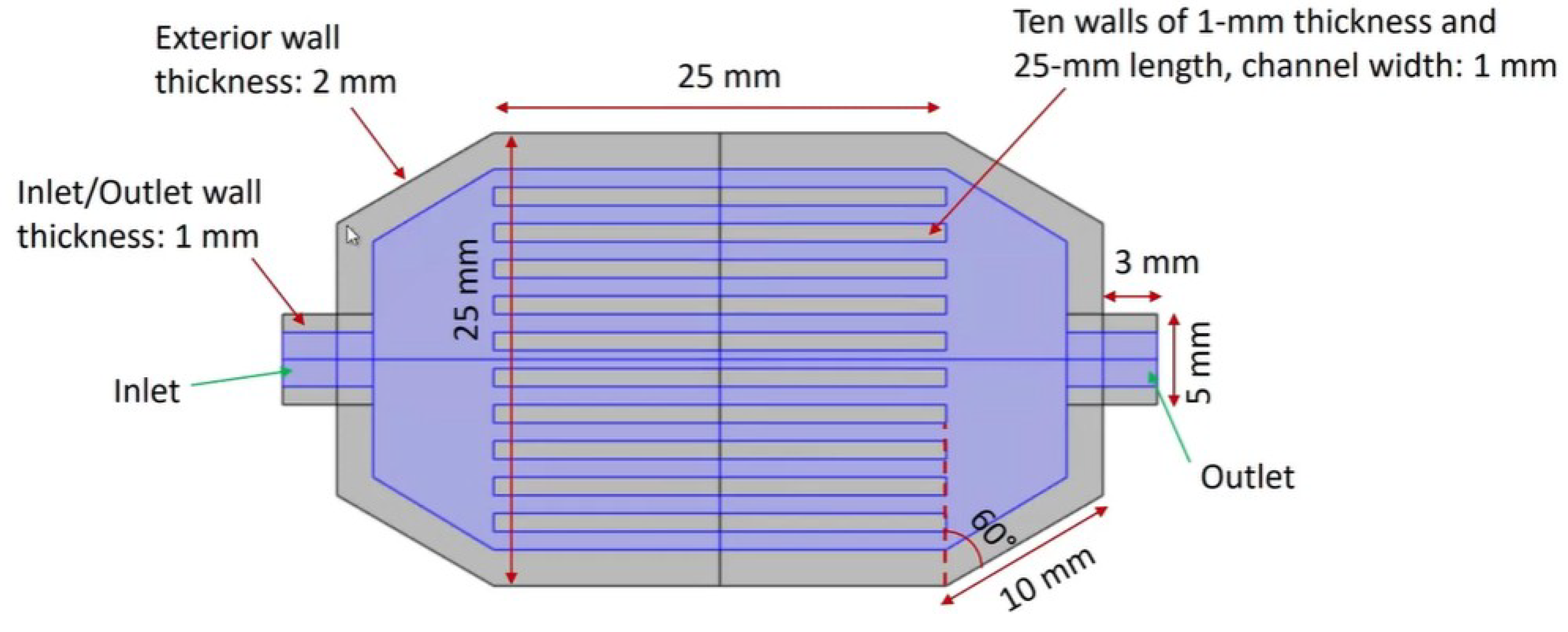
Figure 2.
Side view of the microchannel heat exchanger (MCHX). The main channel section is 25 mm long. Inlet and outlet extensions and circular ports provide space for flow development and connection to external piping or manifolds.
Figure 2.
Side view of the microchannel heat exchanger (MCHX). The main channel section is 25 mm long. Inlet and outlet extensions and circular ports provide space for flow development and connection to external piping or manifolds.
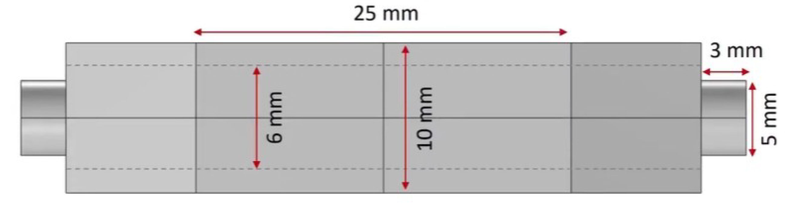
Figure 3.
Three-dimensional COMSOL model of the MCHX, including the copper solid domain and the internal fluid region. Thermal insulation is applied on external walls except at the heated base.
Figure 3.
Three-dimensional COMSOL model of the MCHX, including the copper solid domain and the internal fluid region. Thermal insulation is applied on external walls except at the heated base.
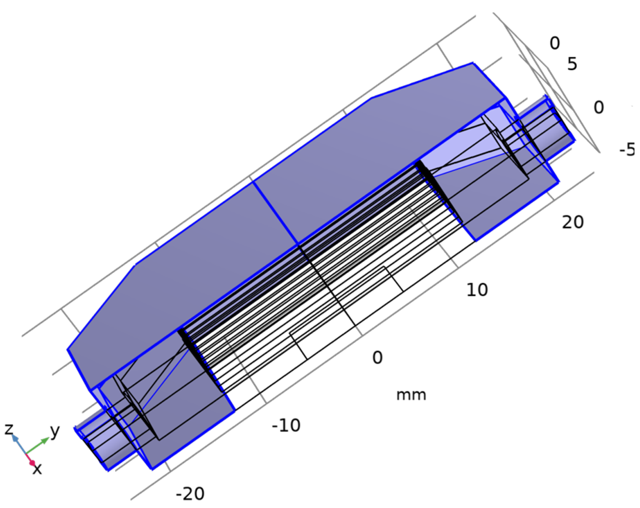
Figure 4.
Physics-controlled mesh of the MCHX geometry in COMSOL. Finer elements are used near solid–fluid interfaces and in narrow regions, while coarser elements are used where the solution varies slowly.
Figure 4.
Physics-controlled mesh of the MCHX geometry in COMSOL. Finer elements are used near solid–fluid interfaces and in narrow regions, while coarser elements are used where the solution varies slowly.
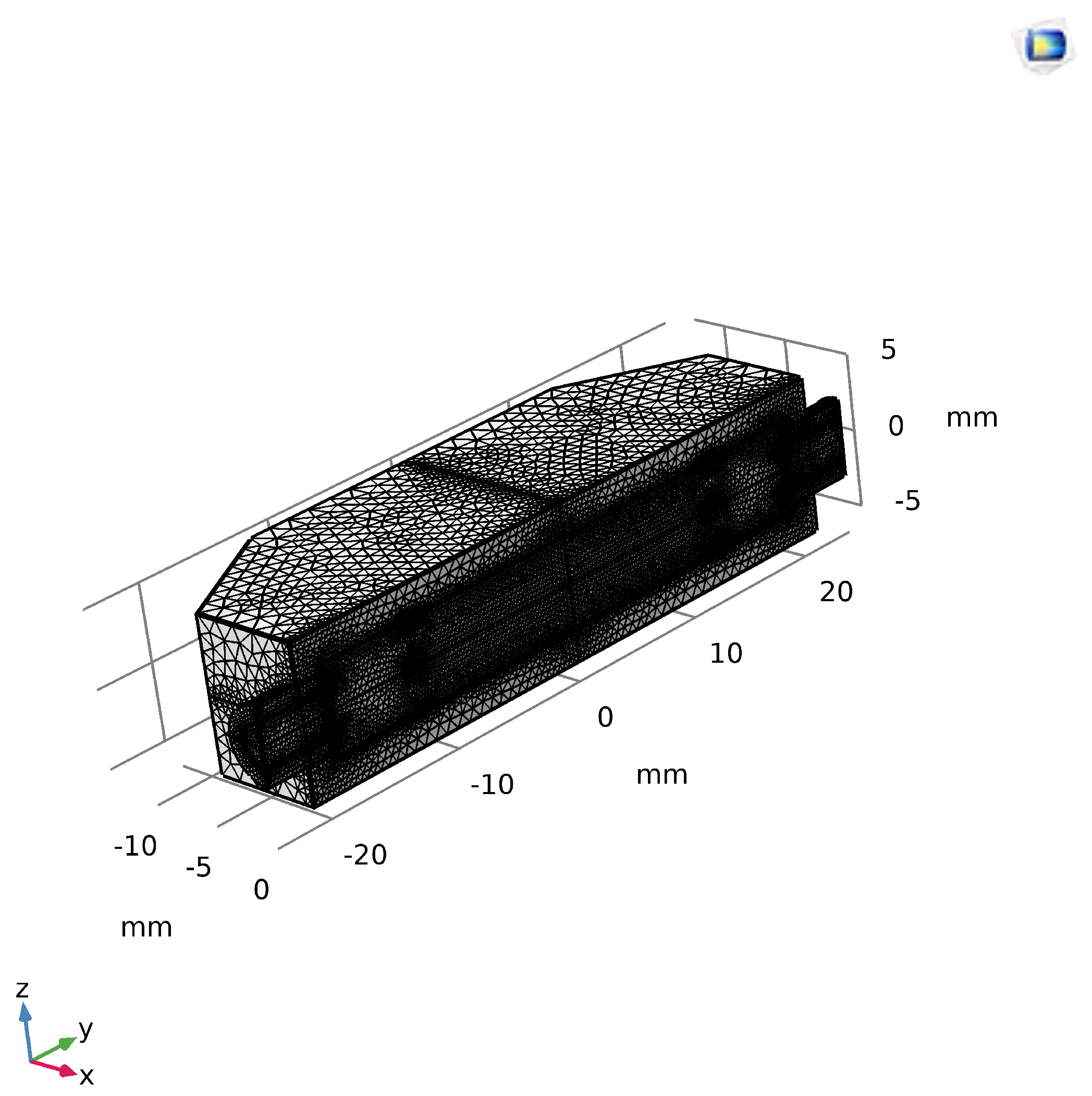
Figure 5.
Two-dimensional surface temperature distribution of the copper microchannel heat sink at an inlet velocity of and inlet temperature of . The temperature increases from inlet to outlet as the coolant picks up heat from the base.
Figure 5.
Two-dimensional surface temperature distribution of the copper microchannel heat sink at an inlet velocity of and inlet temperature of . The temperature increases from inlet to outlet as the coolant picks up heat from the base.
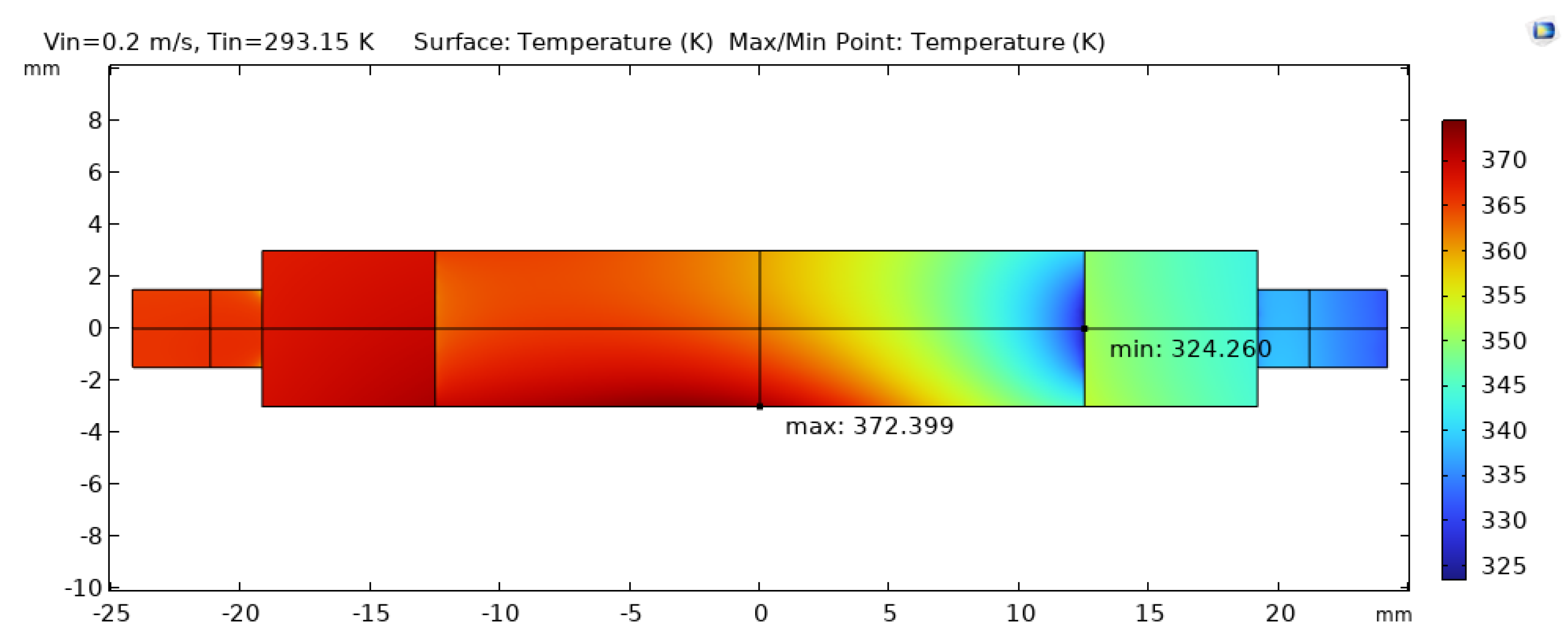
Figure 6.
Three-dimensional temperature distribution in the MCHX at steady state. The hottest regions appear near the heated base toward the outlet, while cooler regions are located near the inlet and at the top surface.
Figure 6.
Three-dimensional temperature distribution in the MCHX at steady state. The hottest regions appear near the heated base toward the outlet, while cooler regions are located near the inlet and at the top surface.
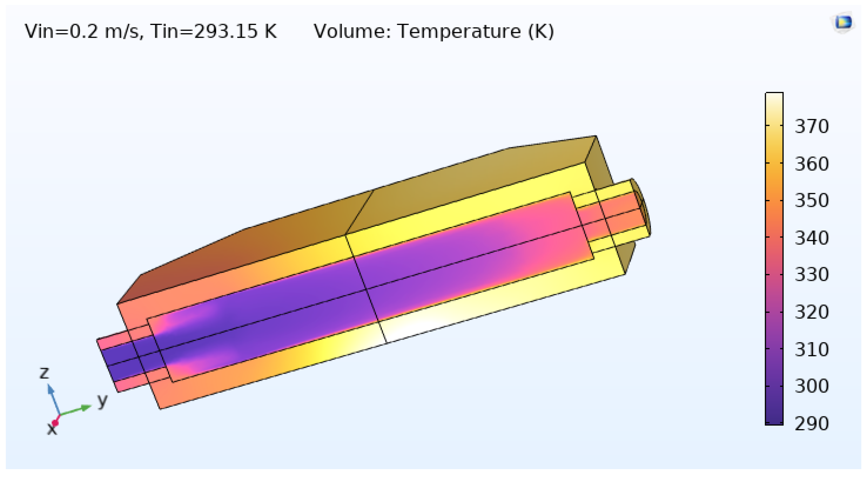
Figure 7.
Mid-plane temperature distribution in the MCHX. The section cut reveals temperature gradients in both the copper solid and the coolant, from the heated base toward the channel outlets.
Figure 7.
Mid-plane temperature distribution in the MCHX. The section cut reveals temperature gradients in both the copper solid and the coolant, from the heated base toward the channel outlets.
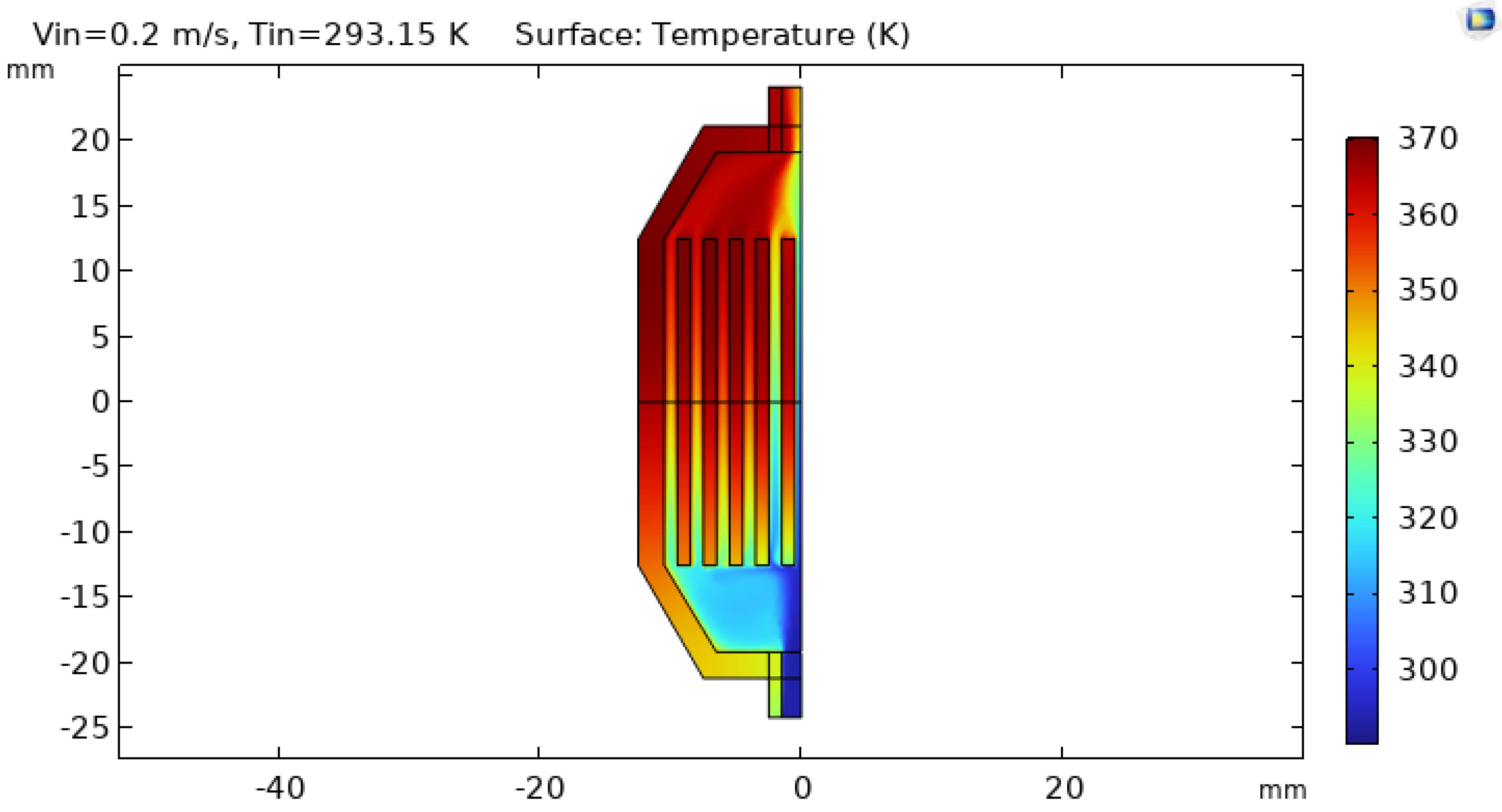
Figure 8.
Velocity magnitude distribution in the MCHX at steady state (, ). Flow remains laminar, and the velocity is fairly uniform across the channels.
Figure 8.
Velocity magnitude distribution in the MCHX at steady state (, ). Flow remains laminar, and the velocity is fairly uniform across the channels.
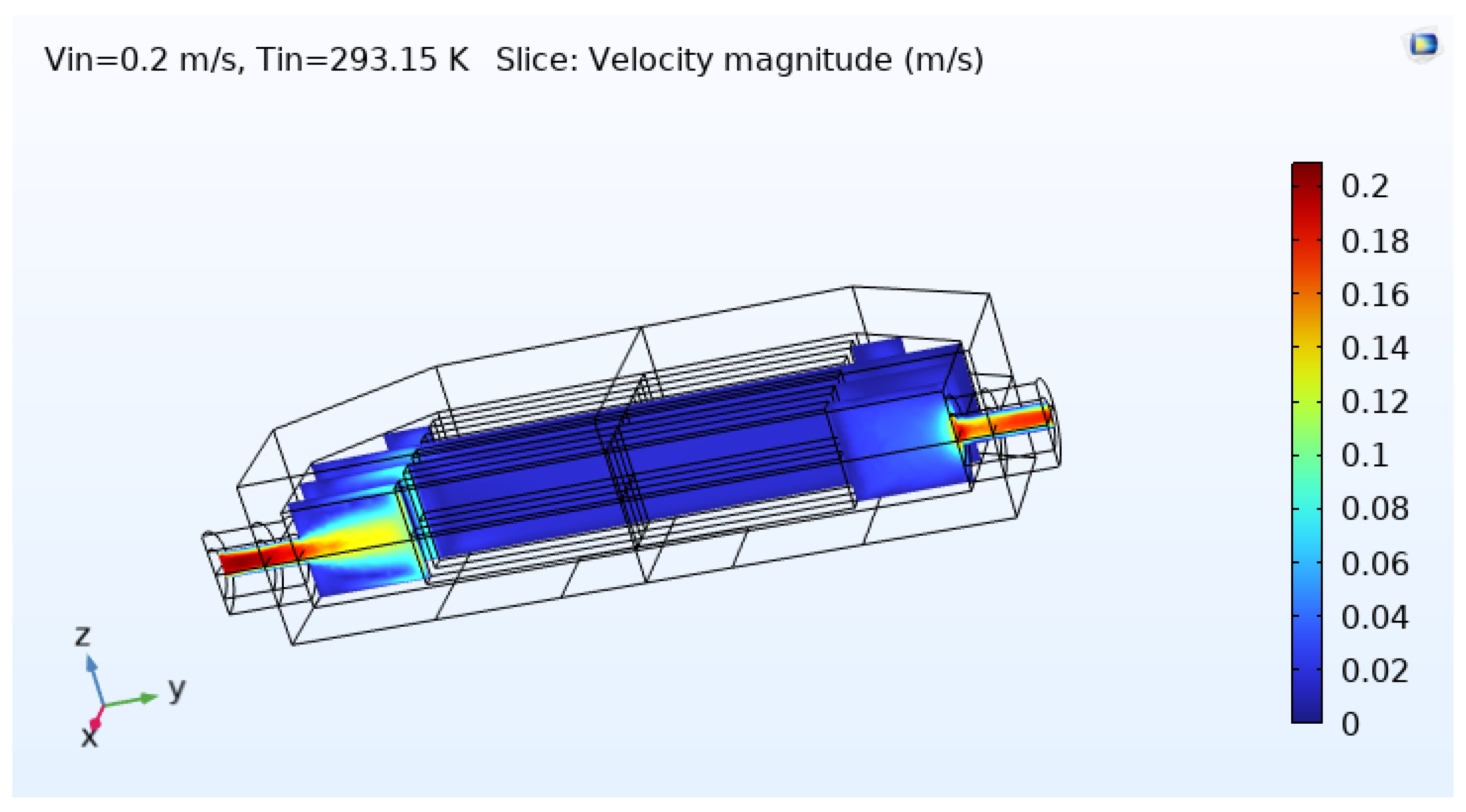
Figure 9.
Pressure distribution within the MCHX at steady state. The nearly linear decrease from inlet to outlet confirms laminar flow and indicates a moderate overall pressure drop.
Figure 9.
Pressure distribution within the MCHX at steady state. The nearly linear decrease from inlet to outlet confirms laminar flow and indicates a moderate overall pressure drop.
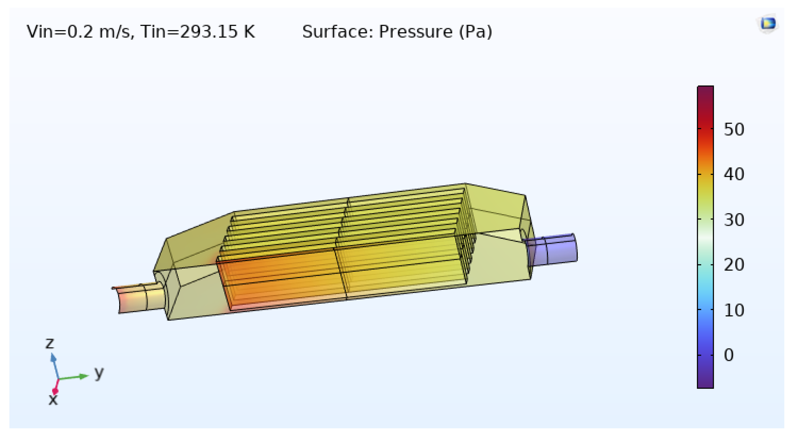
Figure 10.
Combined temperature and velocity field in the MCHX. The plot shows how the coolant accelerates through the channels while picking up heat, linking flow behavior to temperature distribution.
Figure 10.
Combined temperature and velocity field in the MCHX. The plot shows how the coolant accelerates through the channels while picking up heat, linking flow behavior to temperature distribution.
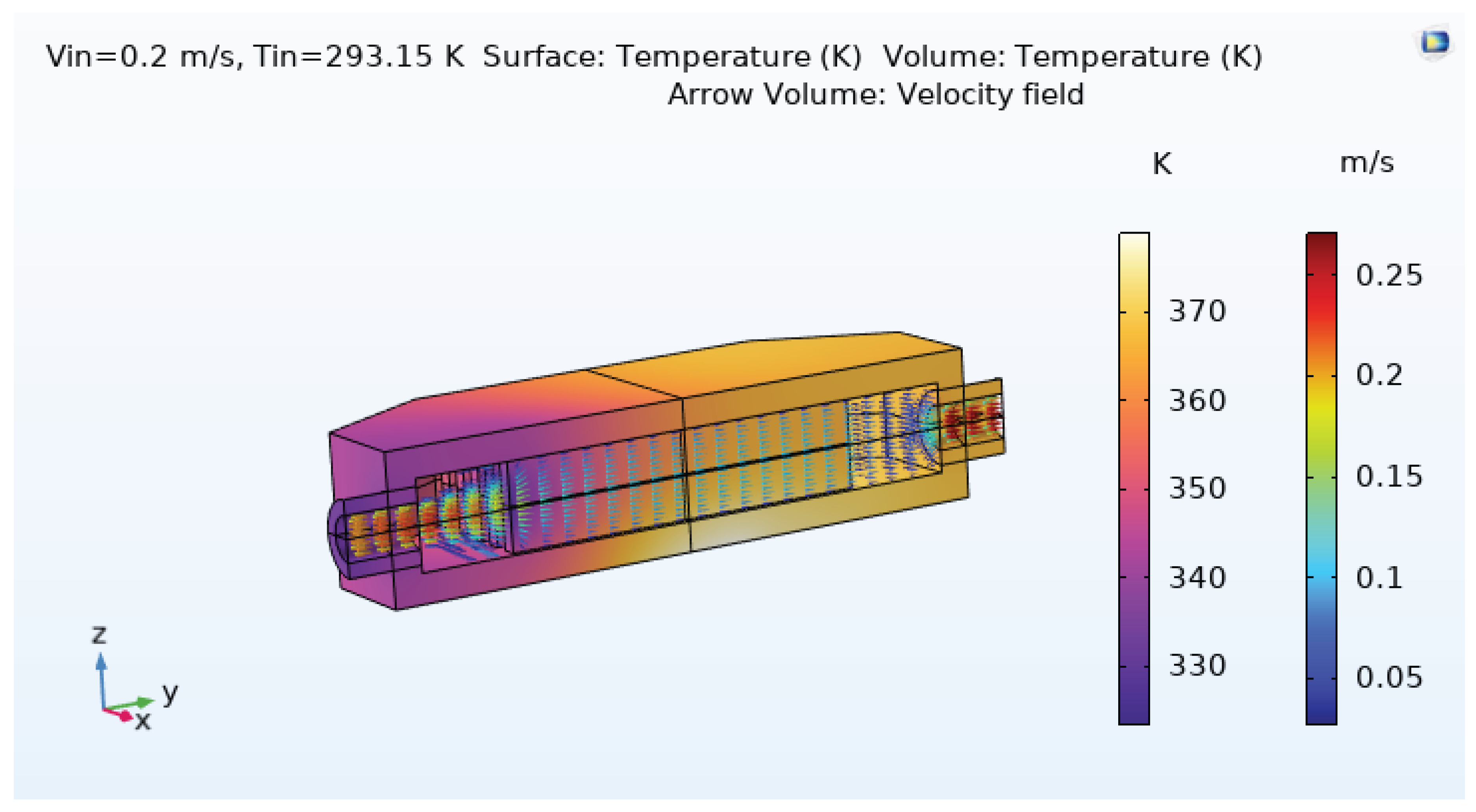
Table 1.
Material and fluid properties used in the model.
| Domain | Material | Density () | Thermal cond. () | Specific heat () |
|---|---|---|---|---|
| Solid | Copper | 8960 | 400 | 385 |
| Fluid | Water (293 K) | 998 | 0.6 | 4182 |
Table 5.
Mesh statistics for coarse, normal, and fine meshes.
| Metric | Coarse | Normal | Fine |
|---|---|---|---|
| Number of elements | 208,651 | 2,956,998 | 1,005,923 |
| Mesh volume () | 4915 | 4916 | 4916 |
| Minimum element quality | 0.09208 | 0.09015 | 0.09521 |
| Average element quality | 0.6403 | 0.6801 | 0.6723 |
Table 6.
Mesh-convergence results for the microchannel heat exchanger.
| Mesh level | Elements | () | () | % change | % change |
|---|---|---|---|---|---|
| Coarse | 208,651 | 358.2 | 165 | – | – |
| Normal | 2,956,998 | 364.9 | 182 | +1.87% | +10.30% |
| Fine | 1,005,923 | 366.1 | 185 | +0.33% | +1.64% |
Disclaimer/Publisher’s Note: The statements, opinions and data contained in all publications are solely those of the individual author(s) and contributor(s) and not of MDPI and/or the editor(s). MDPI and/or the editor(s) disclaim responsibility for any injury to people or property resulting from any ideas, methods, instructions or products referred to in the content. |
© 2025 by the authors. Licensee MDPI, Basel, Switzerland. This article is an open access article distributed under the terms and conditions of the Creative Commons Attribution (CC BY) license (http://creativecommons.org/licenses/by/4.0/).
Copyright: This open access article is published under a Creative Commons CC BY 4.0 license, which permit the free download, distribution, and reuse, provided that the author and preprint are cited in any reuse.


