Submitted:
21 December 2025
Posted:
25 December 2025
You are already at the latest version
Abstract
Carbon Steel SA 178 grade C is a common material used for boiler tubes. A boiler is a crucial unit in the energy industry, meanwhile its services life can be degraded after long term operation. If it malfunctions, the processing operations must be halted, resulting in financial losses for the company. The aim of this study is to examines the effect of microstructural evolution especially transformation of lamellar pearlite into spheroidized pearlite on the service life degradation of boiler tubes. Understanding these changes is essential for preventing catastrophic system failures. The methodology of this study involves the use of Small-Angle X-ray Scattering (SAXS), supported by metallographic analysis, Scanning Electron Microscopy (SEM), Energy-Dispersive X-ray Spectroscopy (EDX), and mechanical testing. The SAXS results indicate that the microstructure of SA-178, initially consisting of lamellar ferrite and pearlite, gradually transforms into spheroidized pearlite. These microstructural changes lead to reductions in tensile strength from 523 MPa for 0% spheroidization to 335 MPa for 100% spheroidization, and hardness from 175HV to 89 HV, ultimately decreasing the service life of the boiler tube.

Keywords:
boiler
; tube
; spheroidized
; pearlite
; neutron
1. Introduction
Majority of Indonesian oil and gas industries equipment had been operated for around 20 and 30 years. This operational duration is already nearing the manufacturer’s recommended lifetime, specifically on the equipment that are running continuously for 24 hours throughout the years at elevated temperature, along with the static load. With the aforementioned condition, the oil and gas industry is demanded to accurately assess the current remaining life time and the integrity of this equipment to prevent catastrophic failure that could cause damage and fatality. Immediate damage example could be seen as simple as production stop, but the effect of indirect damage is as crucial as the immediate damage because it could affect the national economic condition by causing fuel shortage and electricity blackouts across the region [1,2]. Other minor effects of the damage are loss of consumer trust for the affiliated companies in the oil and gas industry. Industrial equipment that are operated in elevated temperature while simultaneously carrying static load will always be undergoing gradual microstructural evolution overtime, which decrease the mechanical properties. Boiler is one of the equipment in energy facilities that carries static load in elevated temperature. The decrease of mechanical properties will consequently reduce the remaining operational life time of the equipment, so that preventive maintenance should be done to avoid catastrophic damage by correctly assessing the equipment’s actual remaining life time [3,4]. During maintenance of power plant boiler components, the remaining life of steel materials is commonly estimated through a combination of non-destructive testing (NDT) and hardness testing. Hardness reflects not only the material’s resistance to deformation but also the extent of long-term degradation. Therefore, the remaining service life of the material can be estimated from changes in hardness data when the operating temperature and pressure are known. However, microstructural inhomogeneity in different regions of the material may lead to anomalous hardness values. To accurately characterize material degradation, both hardness measurements and microstructural observations should be considered. Zhao Q. et.al [5] provide crucial insights into the microstructural evolution of spheroidized pearlite, thereby contributing to a better understanding of its mechanical properties and potential applications in various industrial fields. The spheroidizing process aims to transform carbide particles in steel from irregular, elongated lamellar morphologies into a rounded (spheroidal) form. This transformation significantly alters the carbide particle size and distribution, thereby enhancing the material’s ductility and mechanical strength. Therefore, research about mechanism of service life degradation on SA 178 boiler tubes caused by microstructure evolution is needed. A complete and integrated study should be done to obtain comprehensive data to prevent damage and remaining operational life is known so that a quick decision can be made to avoid losses [5].
2. Materials and Methods
2.1. Materials
Material that selected in this research is medium carbon steel which normally used as boiler pipe and it is standardized by AISI SA 178 grade C. This material has composition as listed in Table 1. Hardness of untreated SA 178 is 175 HV, while its tensile strength is about 325 MPa and yield strength is about 180 MPa. Material of this research is in the form of round bar to make it easier for tensile test specimen to be machined and heat treated [6].
2.2. Methods
The methodology of this study involves the use of Small-Angle X-ray Scattering (SAXS), supported by metallographic analysis, Scanning Electron Microscopy (SEM), Energy Dispersive X-ray Spectroscopy (EDX), and mechanical testing. To obtain spheroidized pearlite at different percentages the specimens are heat treated at various temperature and various holding times. The heat-treated specimens are then evaluated their microstructure, particle size distribution, and percentage of spheroidized pearlite [7]. The parameters of heat treatment are listed in Table 2.
The scanning electron microscopy (SEM) was applied to investigate the microstructure change and to measure the spheroidization ratio (SR) of the specimens. To measure the spheroidization ratio, the SEM micrographs were analyzed by image analysis program (Image J). This program was used to obtain the local information in the area and the aspect ratio of the cementite particles. Refer to Ho Seon Joo et al. the spheroidized cementite particles were considered to be an elliptical shape with an aspect ratio represented by the ratio of the major to minor axes. the cementite was considered to be spheroidized up to the aspect ratio of 5:1. The cementite area was used to calculate the spheroidization ratio (SR), the equation (1) is used for experimental measurements.
Where Vt and Vs are the cementite area of the total and spheroidized cementite area, respectively. However, the calculation of circularity of the cementite using formula in equation (2).
Where As is the spheroidized cementite area and Ps is perimeter of cementite particle. The result is then used as a basic step for testing of mechanical properties as well as neutron scattering. A neutron diffractometer using the neutron diffraction method is used for the characterization of crystal structure, texture, and residual stress. The texture neutron diffractometer (DN2) is installed in the experimental hall of the reactor (XHR) on beam tube S5. DN2 is set to a neutron wavelength of 1.2799 angstroms, using a Helium monitor detector and a BF main detector. Material characterization is conducted at a reactor power of 5 MW using the preset count (PRSC) method. Since the reactor operates only at 5 MW, it is somewhat challenging to perform texture characterization to obtain a complete pole figure, as a minimum power of 15 MW is required. For texture characterization, the sample is placed on an Euler cradle located on the sample table. The sample is then tilted and rotated alternately within a specific angular range. Tilting is performed within the angle range of 0° ≤ χ ≤ 90°, while rotation is carried out within the angle range of 0° ≤ φ ≤ 360°. Moreover, to study the evolution of lamellar pearlite become spheroidized pearlite is implementing Small-Angle X-ray Scattering (SAXS). Mechanical properties tests consist of hot tensile test and hardness test. Another examination to explore pearlite spheroidization is conducted by optical metallography and scanning electron microscope examination as well as Energy Dispersive X-Ray Spectrometer (EDX) to examine the particle composition.
3. Results and Analysis
The results from all tests and examinations provide valuable information that can guide to further discussion.
3.1. Chemical Composition
Chemical composition test result indicated that the specimen composition is in accordance with AISI SA178 grade C specification, there is no impurities elements which are found in the specimens. Detail of chemical composition test can be seen in Table 1. The carbon content is lower (0.18%) than the standard maximum of 0.35%, which means the amount of cementite in the pearlite is lower than the standard specification.
3.2. Metallography examination result
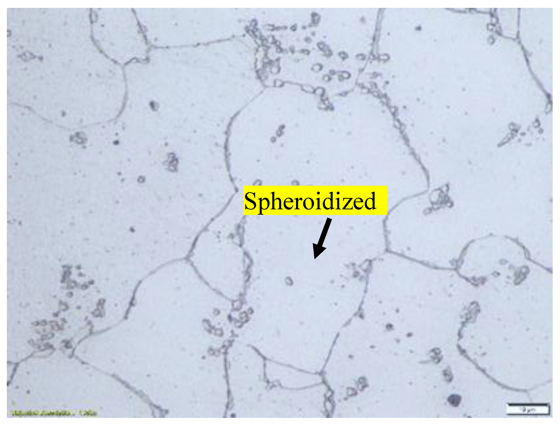
Microstructure of samples either un-heat treated or after heat treated at a particular time and temperatures were examined by optical microscopy. The results are presented starting from Figure 1 to Figure 3. From Figure 1, it is clearly seen that for specimen that has not been heat treated the microstructure of SA 178 material consists of a mixture of ferrite and lamellar pearlite. However, after several hours holding time in high temperature during heat treatment the lamellar pearlite becomes spheroidized [8,9,10] (Figure 2 and Figure 3).
Figure 1.
Microstructure of specimen that has not been heat treated consists of a mixture of ferrite and lamellar pearlite.
Figure 1.
Microstructure of specimen that has not been heat treated consists of a mixture of ferrite and lamellar pearlite.
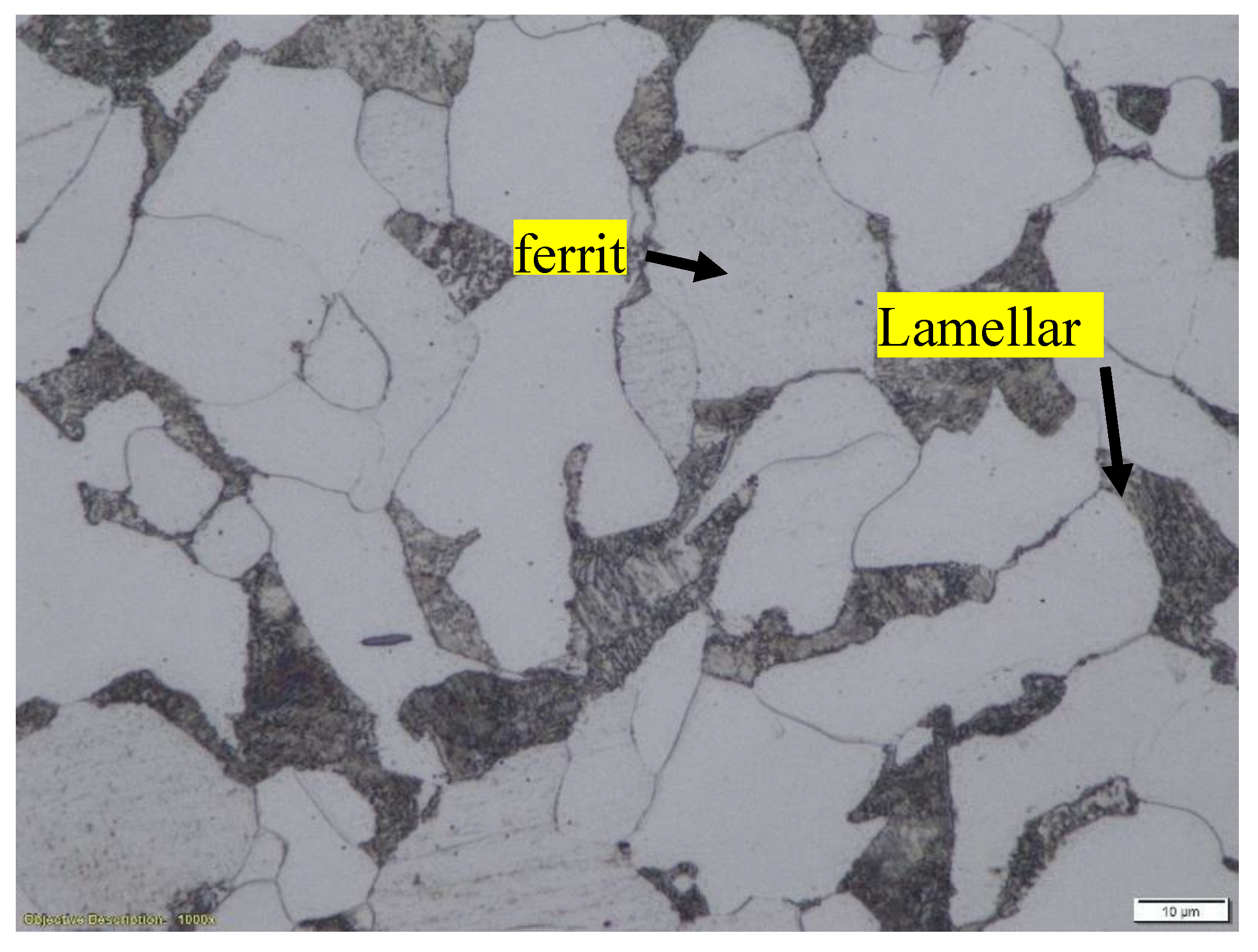
Figure 2.
Microstructure of specimen that has been heat treated at 750 °C for 30 hours. The lamellar pearlite mostly converted to spheroidized pearlite.
Figure 2.
Microstructure of specimen that has been heat treated at 750 °C for 30 hours. The lamellar pearlite mostly converted to spheroidized pearlite.
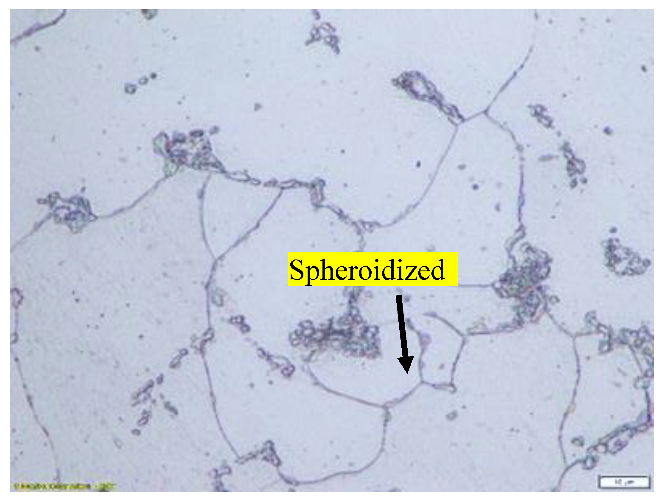
Figure 3.
Microstructure of specimen that has been heat treated at 650 °C for 72 hours. The lamellar pearlite completely converted to spheroidized pearlite.
Figure 3.
Microstructure of specimen that has been heat treated at 650 °C for 72 hours. The lamellar pearlite completely converted to spheroidized pearlite.
3.3. Scanning Electron Microscopy (SEM) examination result
Examination of samples microstructure by SEM either for un-heat treated and for heat treated in particular temperature and holding time can be seen in Figure 4 to Figure 5. From these Figures it confirms that initially pearlite has lamellar cementite (Figure 4). After heat treatment, the lamellar pearlite is transformed to spheroidize pearlite, that means the cementite become spheroidized (Figure 5).
3.4. Energy Dispersive X-ray Spectrometer (EDX) Test
To identify the kind of particles which were formed after heat treatment, Energy Dispersive X-ray (EDX) Spectrometer examination was conducted on samples that had been heated for specific durations and temperatures, as shown in Figure 6 and Table 3. The test results show that the spectrum observed in spheroidized pearlite is dominated by Fe and C, confirming that the particles consist of Fe3C. This indicates that the spheroidized particles originate from the transformation of lamellar Fe3C, which was initially alternating with ferrite in the pearlite structure. There is no other spectra appeared in the EDX analysis at that particle
3.5. Spheroidization ratio taken by image analysis program.
The result of spheroidization ratio taken by image analysis program is presented in Figure 7 and Figure 8. From this figure it is clearly seen that majority of the lamellar pearlite which consist of alternating between ferrite and cementite (carbide) has been broken become small size carbide.
By implemented image analysis, the distribution and percentage of spheroidized pearlite for each specimen can be obtained. Therefore, correlation between heat treatment parameters and percentage of spheroidized pearlite can be observed. It is clearly seen from Figure 2, Figure 3 and Figure 9 that increasing holding time during heat treatment the number of lamellar pearlite transformed to spheroidized pearlite is increasing [11,12]. The effect of annealing time on percentage of spheroidized pearlite can be seen in Figure 9.
From this figure it is clearly seen that the longer time to be exposed in the heat treatment furnace the greater percentage of spheroidized pearlite can be obtained.
3.6. Texture Characterization of Spheroidized Pearlite Using Neutron Diffraction Method
Neutron diffraction is a powerful technique for characterizing the texture of spheroidized pearlite, offering detailed insights into the crystallographic orientation distribution of the material. In this study, a texture neutron diffractometer (DN2) was used, installed in the experimental hall of the reactor (XHR) on beam tube S5. The instrument was operated at a neutron wavelength of 1.2799 angstroms, utilizing a helium (He) monitor detector and a boron trifluoride (BF3) main detector [13,14].
The spheroidized pearlite sample was placed on an Euler cradle mounted on the sample table. The texture measurement process involved tilting (χ) the sample within an angular range of 0° ≤ χ ≤ 90° and rotating (φ) it within 0° ≤ φ ≤ 360°. Data collection was carried out at a reactor power of 5 MW using the preset count (PRSC) method. However, due to the reactor’s operational limitation of 5 MW, obtaining a complete pole figure is challenging, as a minimum power of 15 MW is required for comprehensive texture characterization [15,16,17].
This analysis provides crucial information on the microstructural evolution of spheroidized pearlite, aiding in the understanding of its mechanical properties and potential applications in various industrial fields [18]. The spheroidizing process aims to transform carbide particles in steel from an irregular, elongated lamellar shape into a rounded (spheroid) form. Thus, spheroidized steel can be considered a modification of the steel’s microstructure through a heat treatment process (annealing). This transformation significantly affects the particle size of the material, enhancing its ductility and machinability. From the crystal structure analysis, the spheroidized pearlite sample exhibits a body-centered cubic (BCC) crystal structure with a lattice parameter of 2.8665 angstroms [19,20]. In facts ferrite itself has a BCC structure, but the overall crystallographic characteristics of lamellar pearlite can be complex due to interlamellar interfaces and stress states. The determination of the BCC structure of the spheroidized sample through neutron diffraction and other characterizations indicates that the spheroidization process is a microstructural transformation rather than a fundamental change in the crystal structure.
Inspection using high resolution powder diffractometer (HRPD) where the beam used is neutrons. The difference from the low resolutions powder diffractometer (LRPD) is related to the angular spacing of the measurements, where the HRPD has a smaller spacing compared to the LRPD. As a result, HRPD provides better data accuracy because overlapping peaks can be separated. The HRPD results indicate that the difference in the percentage of spheroidized pearlite affects the appearance of the Fe3C spectrum peak at the 2-theta angle [17,21,22]. The higher the percentage of spheroidized pearlite, the further the spectrum peak shifts to the right, appearing at a larger 2-theta angle (Figure 10).
Additionally, the percentage of spheroidized pearlite also influences the intensity of the Fe3C spectrum, where a higher percentage of spheroidized pearlite results in lower spectrum intensity. This occurs because the atomic configuration in the lamellar form of Fe3C differs from the configuration in the spheroidal form [23,24] [24].
3.7. X-Ray Diffractometer
The XRD examination was conducted on all test specimens that had undergone heat treatment at each percentage of pearlite spheroidization obtained, and the results of the test are shown in Figure 11.
The results of the test specimen examination using an X-Ray Diffractometer (Figure 11) indicate peak shifts, peak broadening, intensity reduction, and the appearance of new peaks. These changes occur because pearlite spheroidization affects the atomic spacing in each structure, transitioning from a lamellar to a spheroidized form, which in turn influences the X-Ray Diffractometer spectrum configuration [25]. The alteration in atomic spacing within the bulk material may lead to a decline in mechanical properties, as dislocation movement within the material becomes easier under external forces, ultimately resulting in a decrease in tensile strength [26,27].
4. Discussion
4.1. Microstructure Evolution
Microstructure of samples after heat treated at a particular time and temperatures were examined by optical and scanning electron microscopy (SEM). From Figure 2, Figure 3 and Figure 5 it is clearly seen that spheroidization of pearlite is highly affected by annealing time and temperature. The longer time to be exposed in the heat treatment furnace the greater percentage of spheroidized pearlite can be obtained (Figure 9). This mean that the longer boiler tubes exposed on high temperature during operation the higher percentage of spheroidized pearlite is formed. From experimental result indicated that time of exposure is more dominant than increasing temperature from 650 °C to 750 °C (Figure 2 and Figure 3). From Figure 7 and Figure 8 indicated that the distribution of spheroidized particle sizes between 0 and 6 hours of annealing indicates that the largest group of spheroidized particles is below 0.225 µm2. These results suggest that the increase in spheroidized particles is due to the fragmentation of lamellar cementite, which occurs at the initial stage of annealing to reduce surface energy [11,12]. As a result of this process, the fractured cementite rapidly transforms into a spherical shape. Specifically, the area fraction of spheroidized cementite with a size of 0.425 µm2 is higher at an 80% spheroidized pearlite percentage. There is little change in both annealing processes at spheroidized pearlite percentages between 40% and 50%, where, during spheroidization, the newly formed particles develop at the same rate as the coarsening of the pre-existing particles [13,14]. The observed distribution at 100% spheroidization shows that spheroidized cementite particles of 0.325 µm2 exhibit a greater increase compared to newly formed spheroidized particles (0.025 µm2). This occurs because, with longer annealing time, the spheroidized particles tend to cluster (agglomerate), resulting in larger spheroidized particles [8]. However, at 100% spheroidization, the spheroidized particles remain below a size of 0.35 µm2. From Figure 7 and Figure 8 show that approximately 131 carbide particles per µm2 undergo spheroidization, indicating that pearlite fragmentation occurs under these conditions. Additionally, the number of carbide particles decreases to 31 particles/mm2 after 72 hours of heat treatment at 700 °C. Pearlite fragmentation continues up to 50 hours during heat treatment at 650 °C in the spheroidization process [15,16].
4.2. Small Angel X-ray Scattering Analysis (SAXS).
Small Angle X-ray Scattering (SAXS) is a widely used technique for analyzing microstructural changes in materials, especially those related to morphological transformations caused by thermal treatment. Research involving quantitative analysis of the spheroidization process in the pearlite system using small-angle scattering techniques with neutrons as the probe has also been conducted. In this study, the spheroidization of cementite in pearlite was analyzed using the SAXS technique for steel with a low carbon content of about 0.32%. The carbon steel was then heat-treated at a temperature of 700 °C through an annealing process with varying durations of 0, 3, 4, 6, 20, 50, and 72 hours. The X-ray scattering data from the measurements log I(q) vs log q(Å-1) can be seen in Figure 12.
To simply observe the effect of heat treatment on low-carbon steel, especially in relation to morphological changes during spheroidization, one can examine the changes in scattering intensity as a function of annealing time. In this case, in Figure 13, the SAXS characterization results can be seen for annealing durations of 3, 4, 50, and 72 hours.
In Figure 13, it is clearly shown that the SAXS scattering patterns exhibit a shift of the scattering peak position toward smaller q values as the annealing time increases. Considering the relationship d = 4π sin(θ) / λ; for small-angle scattering this can be approximated as d = 2π / q, this indicates that atomic diffusion into the core not only enlarges (coarsens) the particles but also increases their spatial separation. This is consistent with SEM observations, which show that with increasing annealing time, particle clustering becomes evident. The decrease in intensity with increasing annealing time is very likely related to the reduction in phase contrast due to accelerated atomic diffusion during heat treatment. In other words, the shift of the peak toward lower q values and the decrease in intensity are caused by microstructural reorganization within the low-carbon steel system. A more quantitative analysis has been carried out using the measured data processed with the SAS View software version 6.0.
4.3. Quantitative Analysis of SAXS Data.
Quantitative analysis of the SAXS data was carried out using the SASView software version 6.0. A PANalytical diffractometer was used for the SAXS measurements, employing X-ray scattering with a Cu-Kα target at room temperature. Prior to the measurements, the sample surface was polished using 1000-grit sandpaper. Based on the SEM observations, the microstructural deformation process of the heat-treated low-carbon steel shows a transition from a lamellar system to a spheroidized system, depending on the annealing duration. The microstructural changes were analyzed using the small-angle X-ray scattering method. In this study, the SAXS data analysis was performed using an Ellipsoid model approach. Considering that, in the low-carbon steel system, it is highly possible for an ellipsoidal ferrite structure to form, surrounded by an Fe3C shell, the SAXS analysis in this research employed the “ellipsoid-core model” (Figure 14) [28].
Based on the analysis of the fitting results shown in Figure 15, it can be seen that in the initial condition, before the annealing process, the material has a very long major axis, which is consistent with the microstructure being in the form of thin lamellar layers. However, after the heat treatment, the major axis of the ellipsoid decreases drastically and then tends to stabilize during further annealing. The change in the length of the major axis with increasing annealing time is very likely related to the microstructural transformation process from a lamellar form toward the formation of spheroidized particles. This is supported by the results of the analysis of the shell thickness, which tends to increase as the annealing time increases, as shown in Figure 16.
Based on the changes in the length of the major axis and the shell thickness, it can be inferred that the microstructural transformation process from a lamellar system to a spheroidized system has already begun during the initial stages of heat treatment at 700 °C and continues throughout the subsequent annealing process. The microstructural changes corresponding to the variations in the SAXS intensity patterns shown in Figure 13 can be confirmed by the changes in the shell volume in relation to the heating duration, as presented in Figure 17.
4.4. Mechanical Properties Evolution
4.4.1. Hardness Value Evolution
Hardness test has been conducted on specimens for spheroidized pearlite at different percentage and presented in Table 4 and Figure 18. It is clearly seen from this table and figure that hardness value is decreased as the percentage of spheroidized pearlite increase. This phenomenon can be explained that by increasing annealing time all of internal stress and grain damaged caused by previous mechanical treatment or machining have been recrystallized and recovered. Moreover, some of pile up dislocations caused by cold working or other cold deformation are annihilated with longer annealing time therefore hardness value is decreased.
Table 4 Vickers Hardness Test Result.
4.4.2. Strength at Elevated Temperature.
To evaluate the mechanical properties changes of spheroidized pearlite specimens of SA 178 steel at elevated temperature, the tensile test was conducted at the boiler’s operational temperature of 275 °C. The test results indicate that as the percentage of spheroidized pearlite increases, the tensile strength decreases (Figure 19).
This occurs because, under tensile loading, dislocations move more easily in the spheroidized pearlite microstructure compared to the lamellar structure [29]. The lamellar pearlite structure presents greater obstacles to dislocation movement, whereas the spheroidized structure allows for easier dislocation motion, leading to a reduction in tensile strength [29]. The effect of annealing time on the mechanical properties of SA 178 shows that by increasing annealing time, the tensile strength obtained is decreasing (Figure 20).
This phenomenon occurs due to several factors, including the increasing percentage of spheroidized pearlite and the reduction of obstacles from deformed grains that have undergone recrystallization. These two factors facilitate dislocation movement under mechanical loading, leading to a decrease in tensile strength at the same time increasing elongation (Figure 21). The lamellar pearlite structure presents greater obstacles to dislocation movement, whereas the spheroidized structure allows for easier dislocation motion, resulting in improved ductility of the metal [30,31].
Annealing time significantly affects the elongation properties of the material, as a longer annealing duration means more thermal energy is applied to the test specimen. This is not only facilitates the transformation of lamellar pearlite into a spheroidized structure but also promotes recrystallization and the rearrangement of atoms into a more ordered configuration. As a result, resistance to dislocation movement decreases, making the material more capable of flowing in the direction of the applied tensile load [32,33]. Consequently, elongation increases with longer annealing time. The spheroidization ratio, calculated as the proportion of spheroidized pearlite area to the total area, indicates that a higher spheroidization ratio corresponds to lower tensile strength. This occurs because the greater the amount of lamellar pearlite that undergoes spheroidization within a given area, the easier it becomes for dislocations to move under tensile loading compared to the lamellar pearlite structure (Figure 22).
5. Conclusions
Based on the results of all tests and examinations and deep analysis for SA 178 boiler material, it can be concluded that:
- ▪ Number of spheroidized pearlite is increasing with additional time of exposure at elevated temperature
- ▪ Higher percentage of pearlite to be spheroidized the tensile strength and hardness of boiler tube material decreases
- ▪ With decreasing of tensile strength and hardness, meaning its ability to withstand operational loads is also reduced.
Therefore, if the operating temperature of boiler remains constant between 250 °C and 350 °C, the remaining service life of the boiler tubes can be estimated by monitoring the percentage of spheroidized pearlite.
Author Contributions
Conceptualization, A.S. and A.A.H.; methodology, A.A.H.; software, E.F. and R; validation, A.Z.S., A.S. and R.; formal analysis, R.,M.R.M, AI.; investigation, E.F, R, S.S, G.C.K.; resources, B.,S.,H.; data curation, E.F., A.A.H, A.I., M.R.M, S.,B., H.; writing—original draft preparation, A.S, R.,E.F.; writing—review and editing, A.S., E.F., R.,A.Z.S.; visualization, E.F., A.S, R., G.C.K, M.R..M.; supervision, A.Z.S., S.S.; project administration, E.F.; funding acquisition, A.S.,A.A.H. All authors have read and agreed to the published version of the manuscript
Funding
The authors disclosed receipt of the following financial support for the authorship, and/or publication of this article: This publication was supported by the Lembaga Pengelola Dana Pendidikan (LPDP) / Indonesia Endowment Fund for Education (IEFE) through scholarship. No: LOG-16032/LPDP.3/2024.
Data Availability Statement
The original contributions presented in this study are included in the article. Further inquiries can be directed to the corresponding author
Acknowledgments
The authors wish to acknowledge LPDP for funding of this research. We also extend our gratitude to the head of OREM-BRIN and his management for managing the whole administration process of this research. We would like to thank to head of PRTKS-BRIN and head of LKS-BRIN laboratory for their guidance throughout this work.
Conflicts of Interest
The authors declare that they have no known competing financial interests or personal relationships that could have appeared to influence the work reported in this paper.
References
- Suhadi, A; Febriyanti, E; Sari, L N. The Role of Failure Analysis on Maintaining Reliability of Oil Refinery for Sustainable Development Goals. In IOP Conference Series: Materials Science and Engineering 1053; IOP Publishing, 2021; p. 012100. [Google Scholar] [CrossRef]
- Chatterjee, U. 2012. MICROSTRUCTURAL IMPRINTS IN FAILURE OF POWER PLANT BOILER TUBES. The International Conference on Applied Mechanics and Mechanical Engineering 15. Egypts Presidential Specialized Council for Education and Scientific Research: 1–12. [CrossRef]
- Suhadi, Amin, Adimas Aprilio, and Eka Febriyanti. 2023. Structural Strength Degradation of Oil and Gas Refinery Equipment. Case Study: Heat Exchanger Tubes of Hydrocarbon Vapor. EVERGREEN Joint Journal of Novel Carbon Resource Sciences & Green Asia Strategy. Vol. 10.
- Syahril, M.; Suhadi, Amin; Febriyanti, Eka; Afandi, Yusuf; Karuana, Feri. Evaluation of refinery unit tube heater condition after ±15 years in service by NDT methods. AIP Conference Proceedings, 2024; American Institute of Physics; Vol. 3069. [Google Scholar] [CrossRef]
- Zhao, Qiu-Hong; Jiang, Bin; Wang, Jia-Mei. Pearlite Spheroidization Mechanism and Lifetime Prediction of 12Cr1MoV Steel used in Power Plant Tianjin special equipment inspection institute; Tianjin, 2016. [Google Scholar]
- Aggen, G; Akstens, Frank W; Michael, C; Adjelian, Allen; Rubeli, Allen; Babu, P; et al. ASM Handbook, Volume 1, Properties and Selection: Irons, Steels, and High Performance Alloys Section: Publication Information and Contributors Publication Information and Contributors Authors and Reviewers; 2005; Vol. 1. [Google Scholar]
- Felipe; Ugioni, Gabrieli Borges; Junca, Eduardo; Arnt, Ângela Beatriz Coelho; da Rocha, Márcio Roberto; Dal-Bó, Alexandre Gonçalves. Heat treatment analysis of astm a106 steel spheroidization and erosive wear at high temperatures. In REM - International Engineering Journal.; Escola de Minas, 2020; Volume 73, pp. 539–546. [Google Scholar] [CrossRef]
- Alcántara, Victor; Alza, Víctor Alcántara. Spheroidizing in Steels: Processes, Mechanisms, Kinetic and Microstructure-A Review. IOSR Journal of Mechanical and Civil Engineering (IOSR-JMCE 18, 63–81. [CrossRef]
- Song, Wenwen; Choi, Pyuck-Pa; Inden, Gerhard; Prahl, Ulrich; Raabe, Dierk; Bleck, Wolfgang. On the spheroidized carbide dissolution and elemental partitioning in a high carbon bearing steel 100Cr6.
- Czarski, A.; Skowronek, T.; Matusiewicz, P. Stability of a lamellar structure - Effect of the true interlamellar spacing on the durability of a pearlite colony. In Archives of Metallurgy and Materials; Committee of Metallurgy, 2015; Volume 60, pp. 2499–2503. [Google Scholar] [CrossRef]
- Amos, P. G.Kubendran; Bhattacharya, Avisor; Nestler, Britta; Ankit, Kumar. Mechanisms of pearlite spheroidization: Insights from 3D phase-field simulations. In Acta Materialia; Acta Materialia Inc, 2018; Volume 161, pp. 400–411. [Google Scholar] [CrossRef]
- Bhadeshia, H K D H. Interpretation of the microstructure of steels.
- Joo, Ho Seon; Hwang, Sun Kwang; Baek, Hyun Moo; Im, Yong Taek; Son, Il Heon; Bae, Chul Min. The effect of a non-circular drawing sequence on spheroidization of medium carbon steel wires. In Journal of Materials Processing Technology; Elsevier Ltd., 2015; Volume 216, pp. 348–356. [Google Scholar] [CrossRef]
- Nutal, Nicolas; Gommes, Cedric J.; Blacher, Silvia; Pouteau, Philippe; Pirard, Jean Paul; Boschini, Frédéric; Traina, Karl; Cloots, Rudi. Image analysis of pearlite spheroidization based on the morphological characterization of cementite particles. In Image Analysis and Stereology; International Society for Stereology, 2010; Volume 29, pp. 91–98. [Google Scholar] [CrossRef]
- Wang, Shifu; Cao, Luowei; Zhang, Zheng. Influence of carbide morphology on the deformation and fracture mechanisms of spheroidized 14CrMoR steel. In Metals; MDPI AG, 2019; Volume 9. [Google Scholar] [CrossRef]
- O’brien, James M; Hosford, William F. Spheroidization Cycles for Medium Carbon Steels.
- Su, Yuhua; Morooka, Satoshi; Ohnuma, Masato; Suzuki, Junichi; Tomota, Yo. Quantitative Analysis of Cementite Spheroidization in Pearlite by Small-Angle Neutron Scattering. In Metallurgical and Materials Transactions A: Physical Metallurgy and Materials Science; Springer Boston, 2015; Volume 46, pp. 1731–1740. [Google Scholar] [CrossRef]
- Tomota, Yo; Wang, Yan Xu; Ohmura, Takahito; Sekido, Nobuaki; Harjo, Stefanus; Kawasaki, Takuro; Gong, Wu; Taniyama, Akira. In situ neutron diffraction study on ferrite and pearlite transformations for a 1.5Mn-1.5Si-0.2C steel. In ISIJ International; Iron and Steel Institute of Japan, 2018; Volume 58, pp. 2125–2132. [Google Scholar] [CrossRef]
- Tejero-Martin, Daniel; Bai, Mingwen; Mata, Jitendra; Hussain, Tanvir. Evolution of porosity in suspension thermal sprayed YSZ thermal barrier coatings through neutron scattering and image analysis techniques. In Journal of the European Ceramic Society; Elsevier Ltd., 2021; Volume 41, pp. 6035–6048. [Google Scholar] [CrossRef]
- Onuki, Yusuke; Hirano, Takashi; Hoshikawa, Akinori; Sato, Shigeo; Tomida, Toshiro. In Situ Observation of Bainite Transformation and Simultaneous Carbon Enrichment in Austenite in Low-Alloyed TRIP Steel Using Time-of-Flight Neutron Diffraction Techniques. In Metallurgical and Materials Transactions A: Physical Metallurgy and Materials Science; Springer Boston, 2019; Volume 50, pp. 4977–4986. [Google Scholar] [CrossRef]
- Gray, V.; Galvin, D.; Sun, L.; Gilbert, E. P.; Martin, T.; Hill, P.; Rawson, M.; Perkins, K. Precipitation in a novel maraging steel F1E: A study of austenitization and aging using small angle neutron scattering. In Materials Characterization; Elsevier Inc., 2017; Volume 129, pp. 270–281. [Google Scholar] [CrossRef]
- Chung; Ping, Ping; Mata, Jitendra; Wang, James; Durandet, Yvonne. Application of Small- and Ultra-Small-Angle Neutron Scattering for the Characterization of Mechanically Plated Coatings. [CrossRef]
- Ji, Yeping; Radlinski, Andrzej P.; Blach, Tomasz; de Campo, Liliana; Vu, Phung; Roshan, Hamid; Regenauer-Lieb, Klaus. How to avoid multiple scattering in strongly scattering SANS and USANS samples. In Fuel 325; Elsevier Ltd, 2022. [Google Scholar] [CrossRef]
- Barré, Loic. Contribution of small-angle X-ray and neutron scattering (SAXS and SANS) to the characterization of natural nanomaterials. In X-ray and Neutron Techniques for Nanomaterials Characterization; Springer Berlin Heidelberg, 2016; pp. 665–716. [Google Scholar] [CrossRef]
- Gräwert, Melissa; Svergun, Dmitri. 4.0 (CC BY-NC-ND) Beginner’s Guide A beginner’s guide to solution small-angle X-ray scattering (SAXS) 2020.
- Simm, Thomas Hadfield; Sun, Lin; Galvin, Deri Rhys; Hill, Paul; Rawson, Martin; Birosca, Soran; Gilbert, Elliot Paul; Bhadeshia, Harshad; Perkins, Karen. The effect of a two-stage heat-treatment on the microstructural and mechanical properties of a maraging steel. In Materials; MDPI AG, 2017; Volume 10. [Google Scholar] [CrossRef]
- Shin, E. J.; Seong, B. S.; Han, Y. S.; Lee, C. H.; Kim, H. R. Study of precipitate and texture in low-carbon steels by neutron scattering techniques. In Physica B: Condensed Matter; Elsevier, 2004; Vol. 350. [Google Scholar] [CrossRef]
- Nist Igor/Danse, and Steve King. 2025. core_shell_ellipsoid. https://www.sasview.org/docs/user/models/core_shell_ellipsoid.html. December 21.
- Seong, B. S.; Cho, Y. R.; Shin, E. J.; Kim, S. I.; Choi, S. H.; Kim, H. R.; Kim, Y. J. Study of the effect of nano-sized precipitates on the mechanical properties of boron-added low-carbon steels by neutron scattering techniques. Journal of Applied Crystallography 2008, 41, 906–912. [Google Scholar] [CrossRef] [PubMed]
- Mates, Steven; Stoudt, Mark; Gangireddy, Sindhura. Measuring the Influence of Pearlite Dissolution on the Transient Dynamic Strength of Rapidly Heated Plain Carbon Steels. In JOM 68; Minerals, Metals and Materials Society, 2016; pp. 1832–1838. [Google Scholar] [CrossRef]
- Jia, N.; Shen, Y. F.; Liang, J. W.; Feng, X. W.; Wang, H. B.; Misra, R. D.K. Nanoscale spheroidized cementite induced ultrahigh strength-ductility combination in innovatively processed ultrafine-grained low alloy medium-carbon steel. In Scientific Reports; Nature Publishing Group, 2017; Volume 7. [Google Scholar] [CrossRef]
- Chen, Jun; Jin, Shi Jie; Qiao, Dan. Nondestructive evaluation of microstructure degradation of pearlitic steel. Proceedings of 2020 IEEE Far East NDT New Technology and Application Forum, FENDT 2020, 2020; Institute of Electrical and Electronics Engineers Inc; pp. 27–30. [Google Scholar] [CrossRef]
- Grygier, Dominika; Dudziński, Włodzimierz; Gerstein, Gregory; Nürnberger, Florian. The effectiveness of spheroidization pearlitic steel with regard to the degree of plastic deformation.
Figure 4.
Microstructure of specimen that has not been heat treated shows clearly that pearlite is in the form of lamellar structure.
Figure 4.
Microstructure of specimen that has not been heat treated shows clearly that pearlite is in the form of lamellar structure.
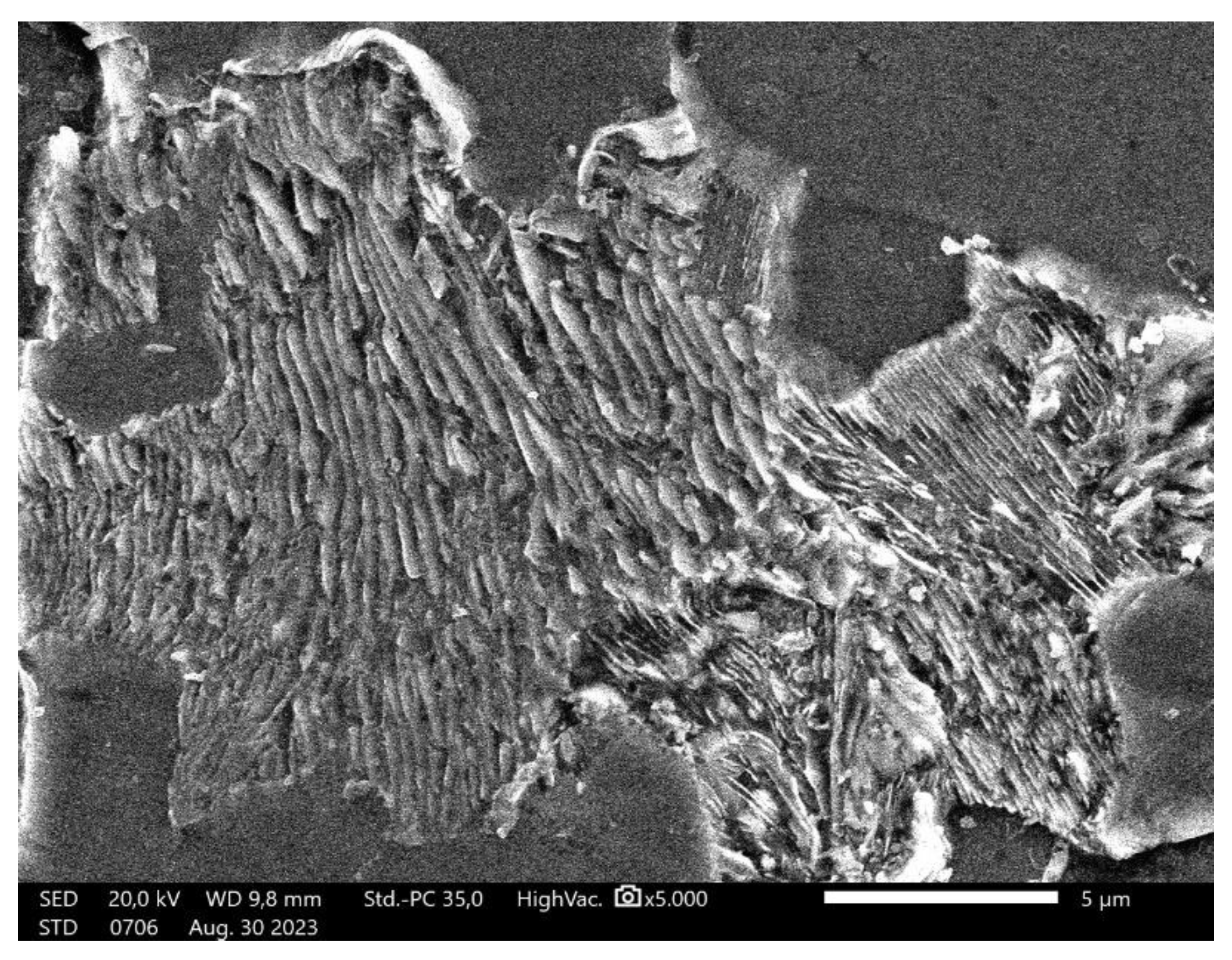
Figure 5.
(a) SEM result of specimen that has been heat treated at 750 °C for 30 hours. Most of the lamellar pearlite are converted to spheroidized pearlite; (b) SEM of specimen that has been heat treated at 650 °C for 72 hours. The lamellar pearlite completely converted to spheroidized pearlite.
Figure 5.
(a) SEM result of specimen that has been heat treated at 750 °C for 30 hours. Most of the lamellar pearlite are converted to spheroidized pearlite; (b) SEM of specimen that has been heat treated at 650 °C for 72 hours. The lamellar pearlite completely converted to spheroidized pearlite.
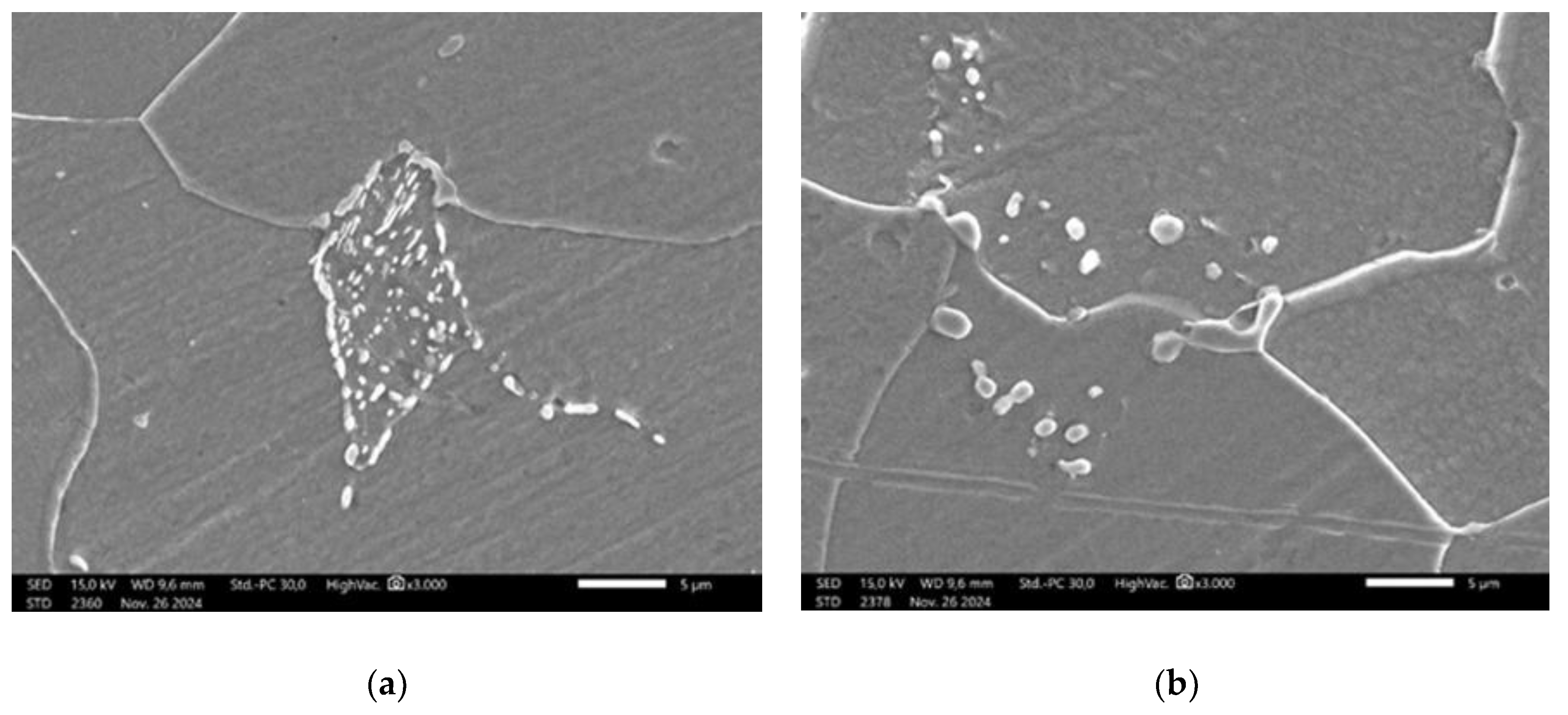
Figure 6.
(a) EDX test location on particle that formed after heat treatment; (b) Spectrum of EDX test on particle which is suspected as spheroidized cementite.
Figure 6.
(a) EDX test location on particle that formed after heat treatment; (b) Spectrum of EDX test on particle which is suspected as spheroidized cementite.
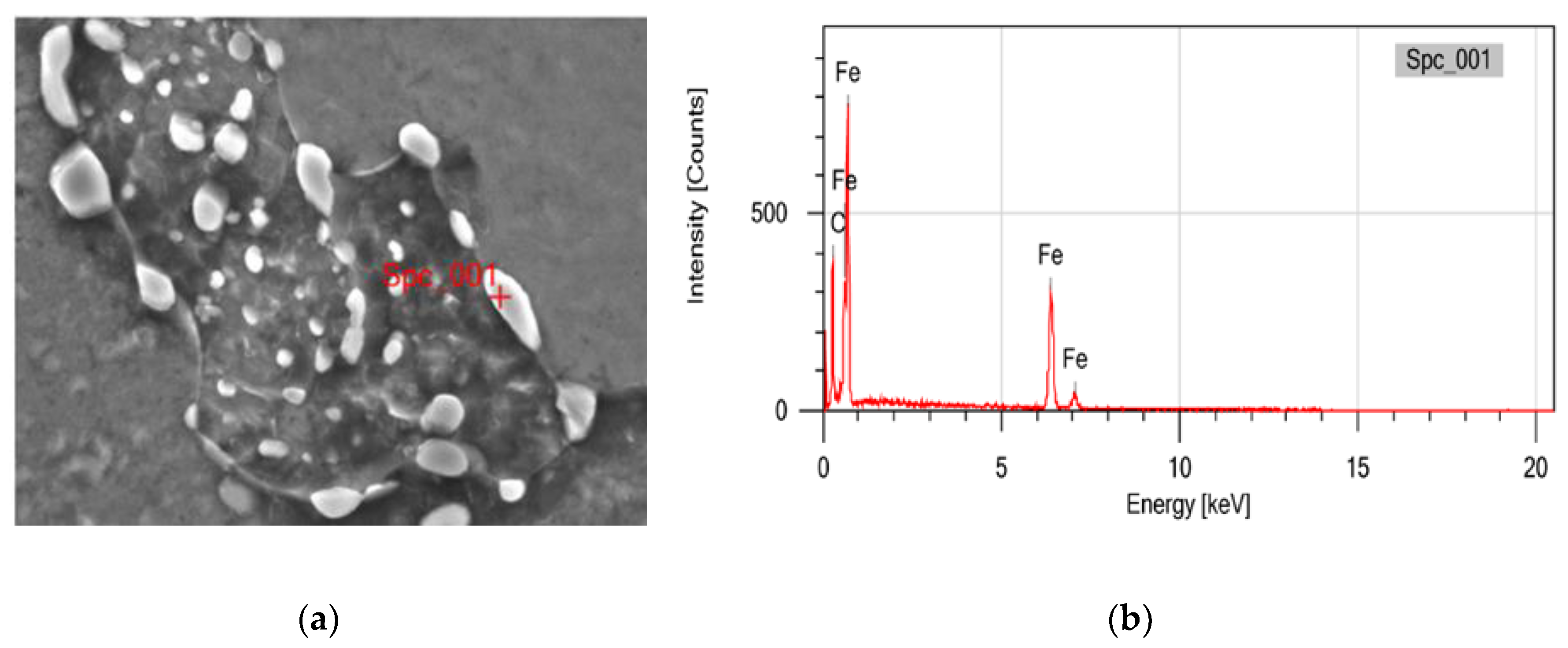
Figure 7.
The distribution of carbide quantity (per µm2) vs. carbide area (µm2) for specimens subjected to heat treatment with varying spheroidization ratios (%).
Figure 7.
The distribution of carbide quantity (per µm2) vs. carbide area (µm2) for specimens subjected to heat treatment with varying spheroidization ratios (%).
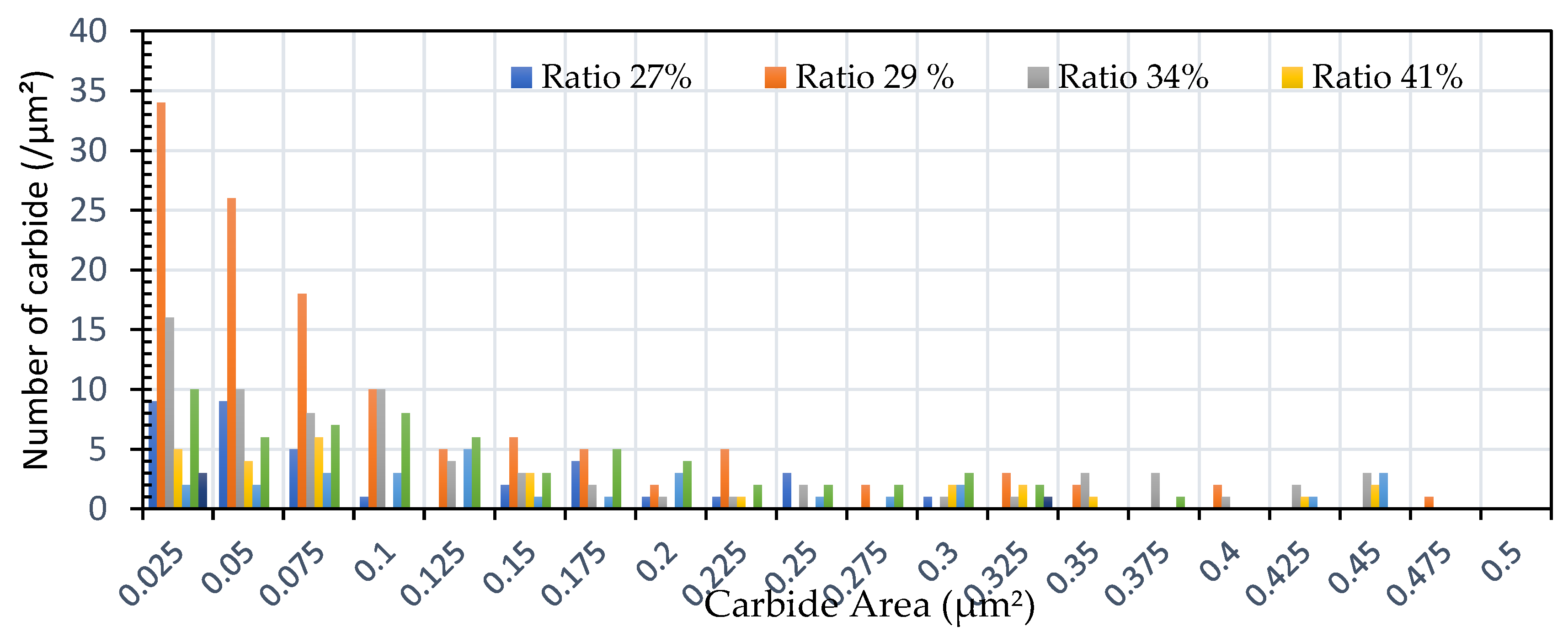
Figure 8.
The distribution of carbide quantity (per µm2) vs carbide area (µm2) for specimens subjected to heat treatment with varying spheroidized pearlite percentages (%).
Figure 8.
The distribution of carbide quantity (per µm2) vs carbide area (µm2) for specimens subjected to heat treatment with varying spheroidized pearlite percentages (%).
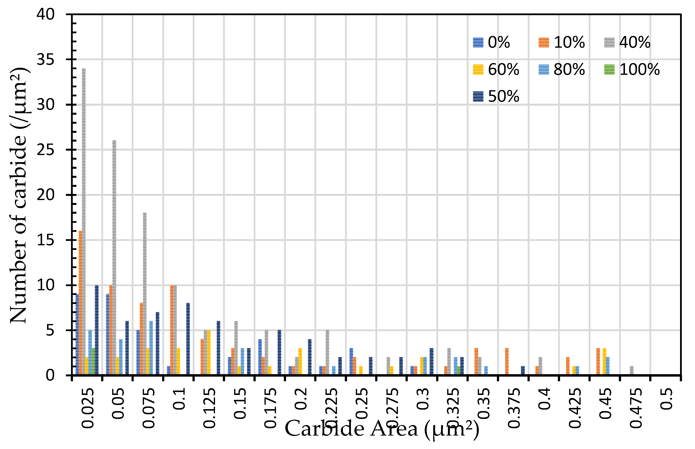
Figure 9.
Percentage of spheroidized pearlite against annealing time. .
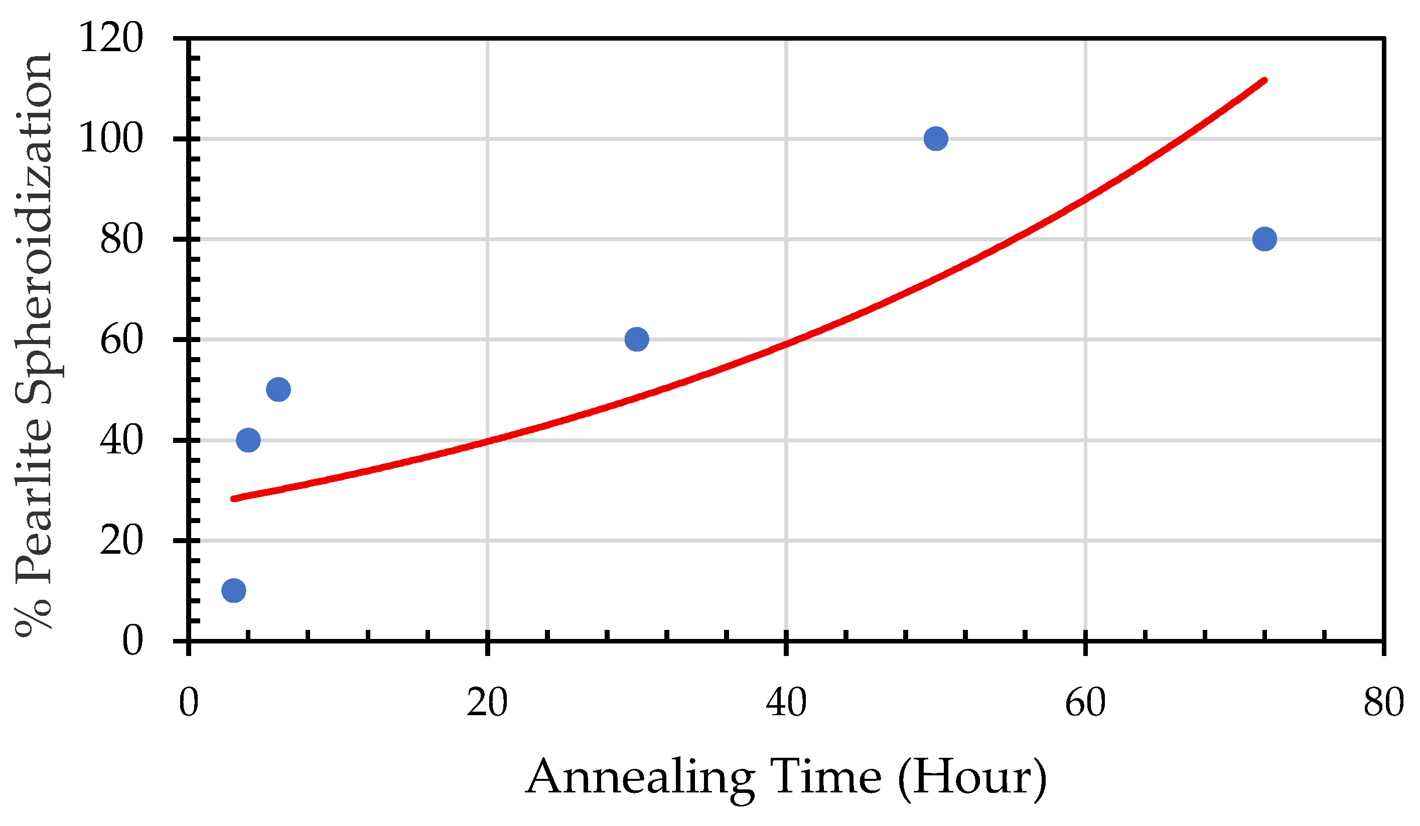
Figure 10.
HRPD Characterization of Spheroidized pearlite using neutron beam.
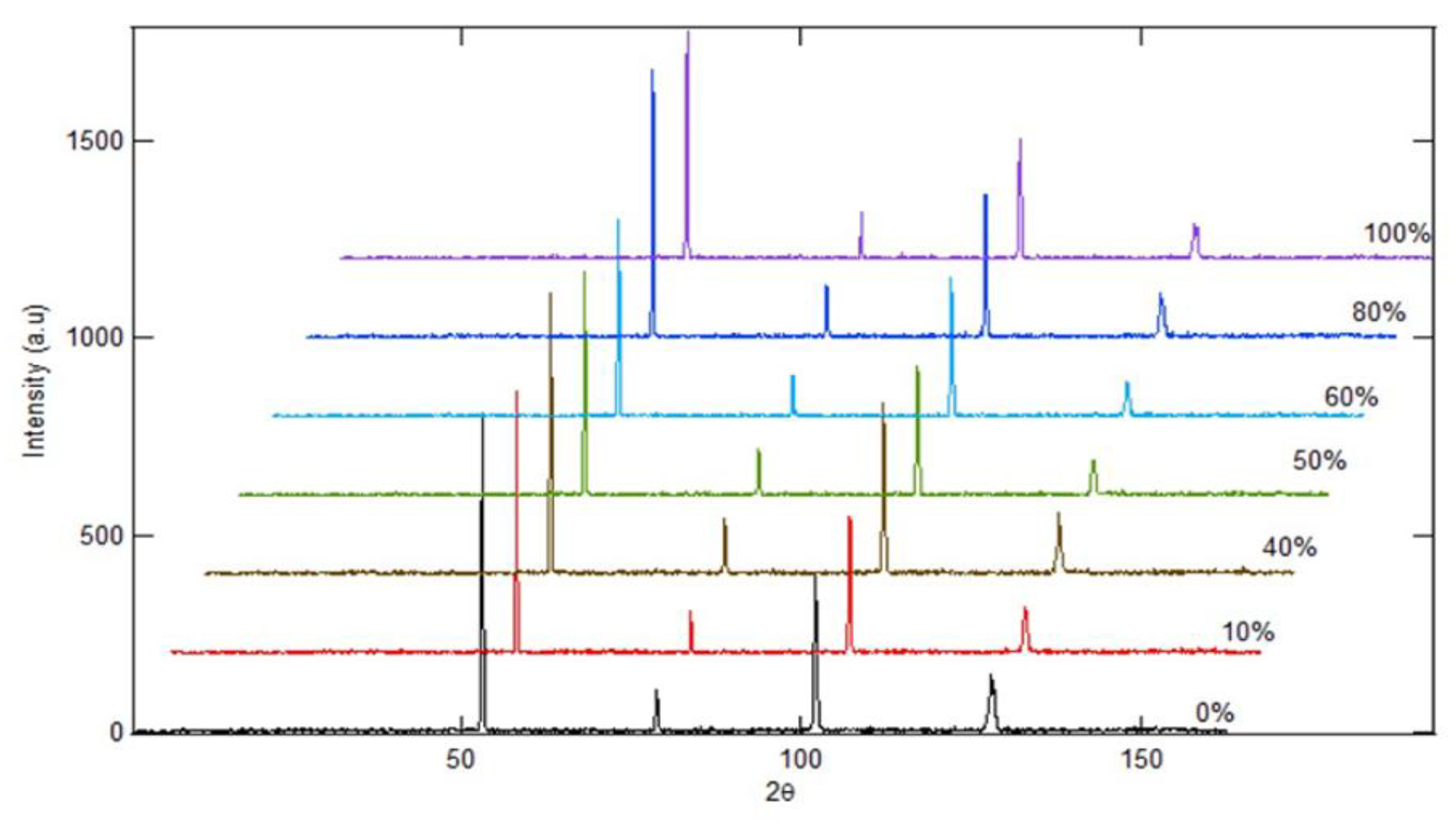
Figure 11.
(a) The results of X-Ray Diffractometer (XRD) analysis with observations on one of the spectrum angles, 2θ, in the range of 40-50. (b) The magnification of Figure 11 (a) shows a shift in the spectrum peak.
Figure 11.
(a) The results of X-Ray Diffractometer (XRD) analysis with observations on one of the spectrum angles, 2θ, in the range of 40-50. (b) The magnification of Figure 11 (a) shows a shift in the spectrum peak.
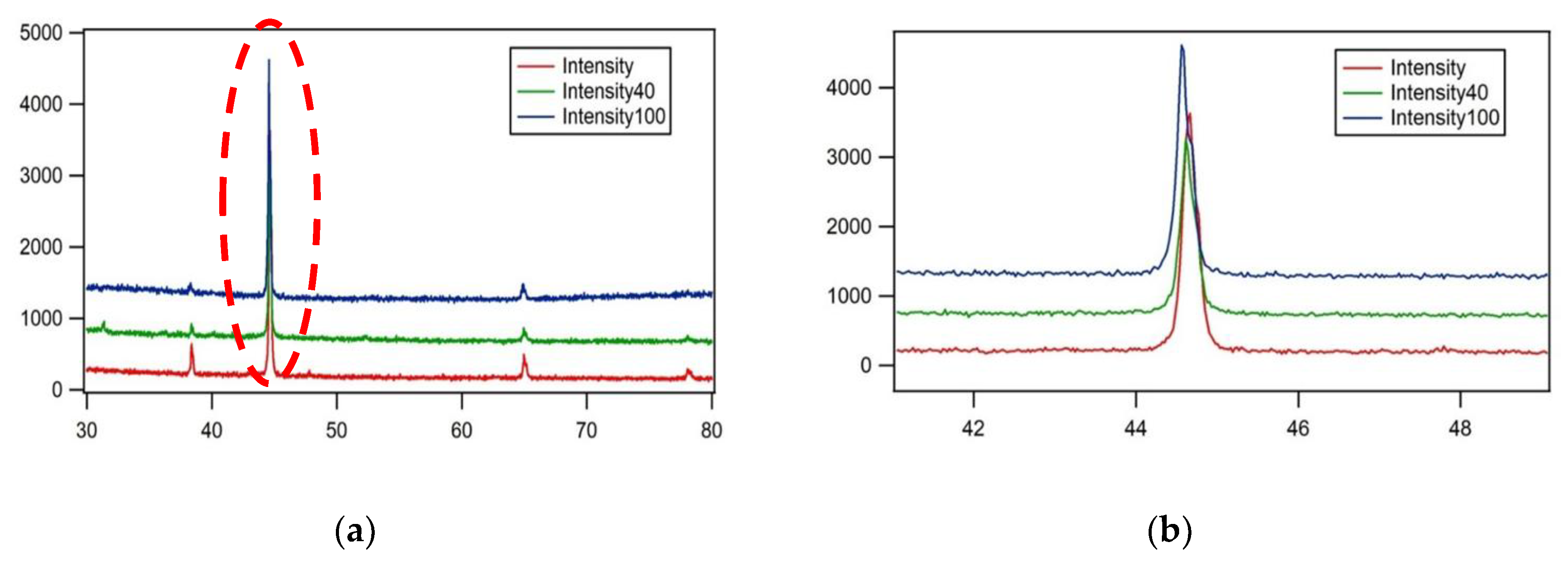
Figure 12.
SAXS scattering patterns of 0.32% carbon steel after annealing at 700 °C for durations of 0, 3, 4, 5, 20, 50, and 72 hours.
Figure 12.
SAXS scattering patterns of 0.32% carbon steel after annealing at 700 °C for durations of 0, 3, 4, 5, 20, 50, and 72 hours.
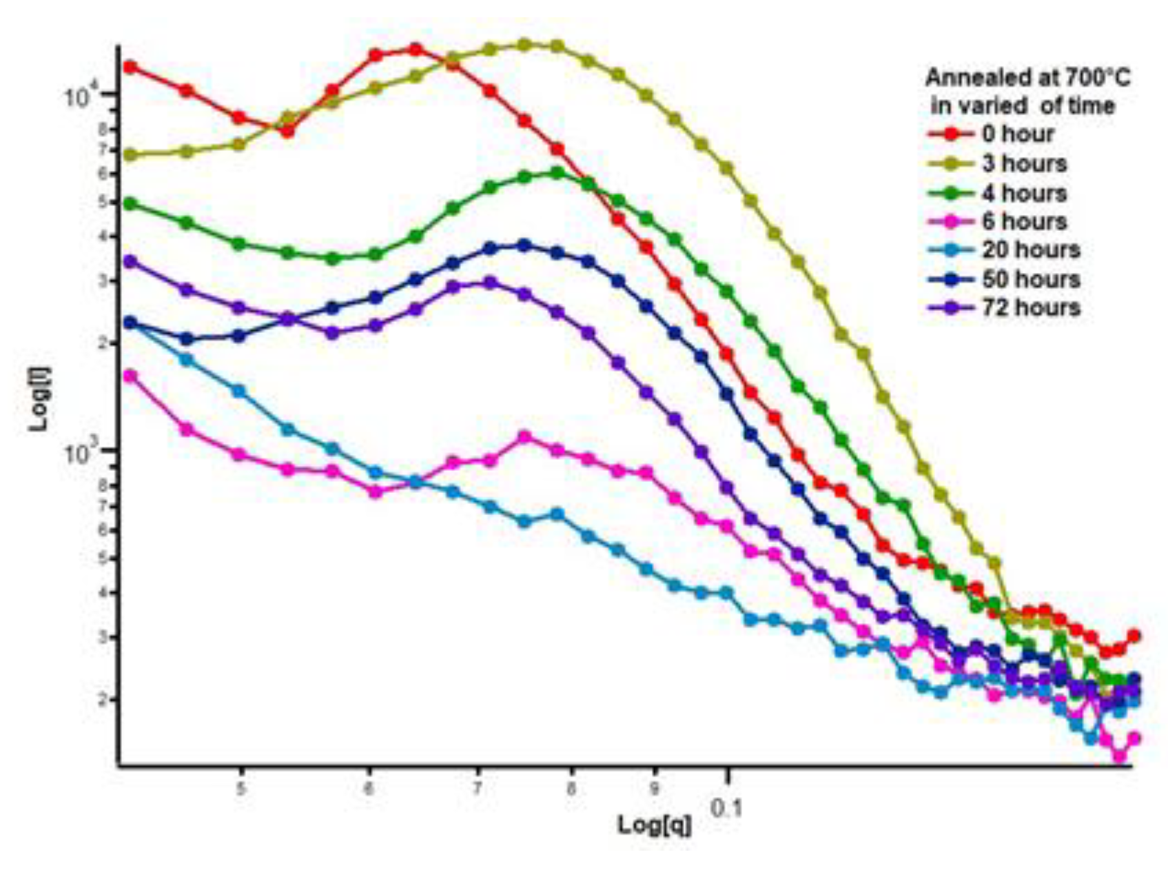
Figure 13.
SAXS scattering patterns from the heat-treated low-carbon steel at 700 °C for annealing durations of 3, 4, 50, and 72 hours.
Figure 13.
SAXS scattering patterns from the heat-treated low-carbon steel at 700 °C for annealing durations of 3, 4, 50, and 72 hours.
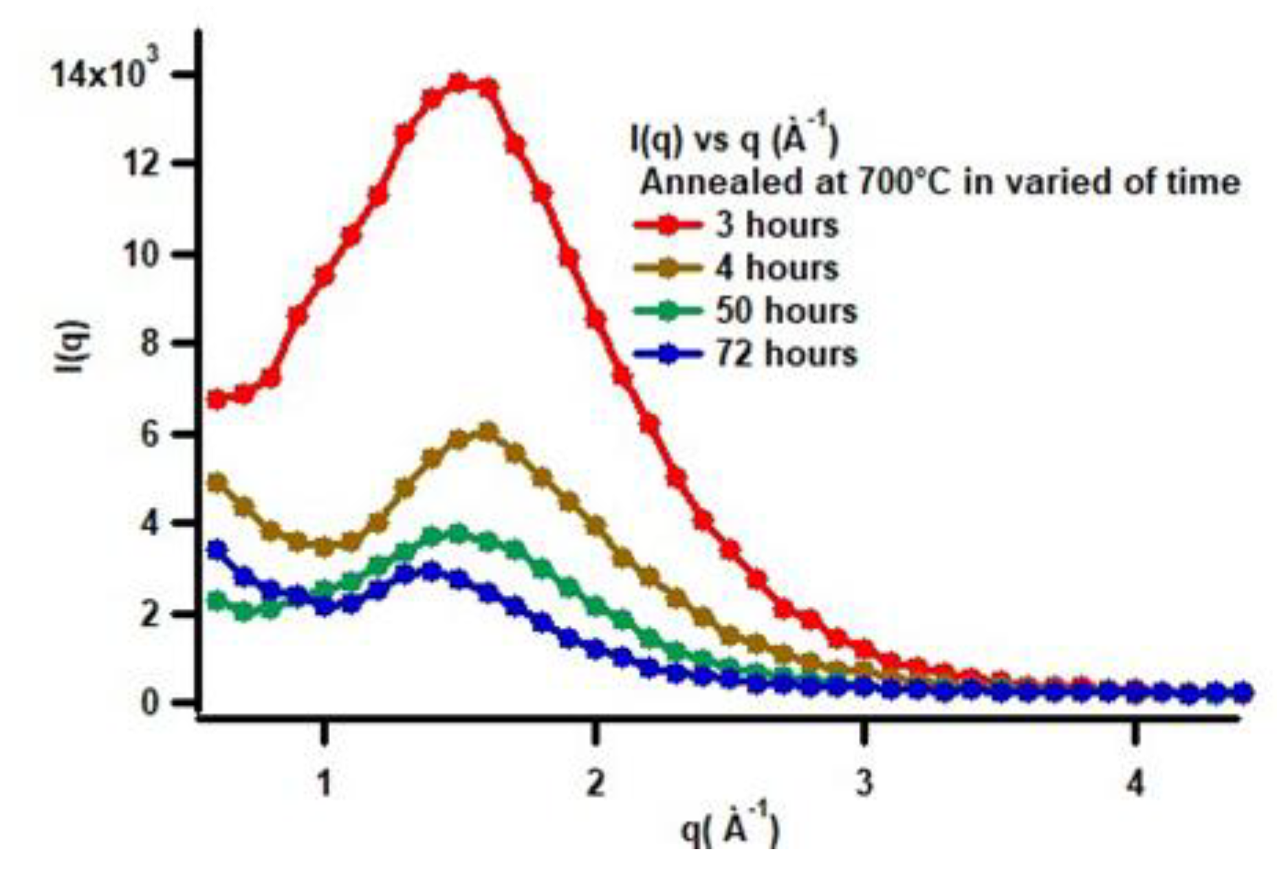
Figure 14.
The geometric parameters of this model shows (a) a cut through at the circular equator, and (b) a cross section through the poles, of a prolate ellipsoid.
Figure 14.
The geometric parameters of this model shows (a) a cut through at the circular equator, and (b) a cross section through the poles, of a prolate ellipsoid.
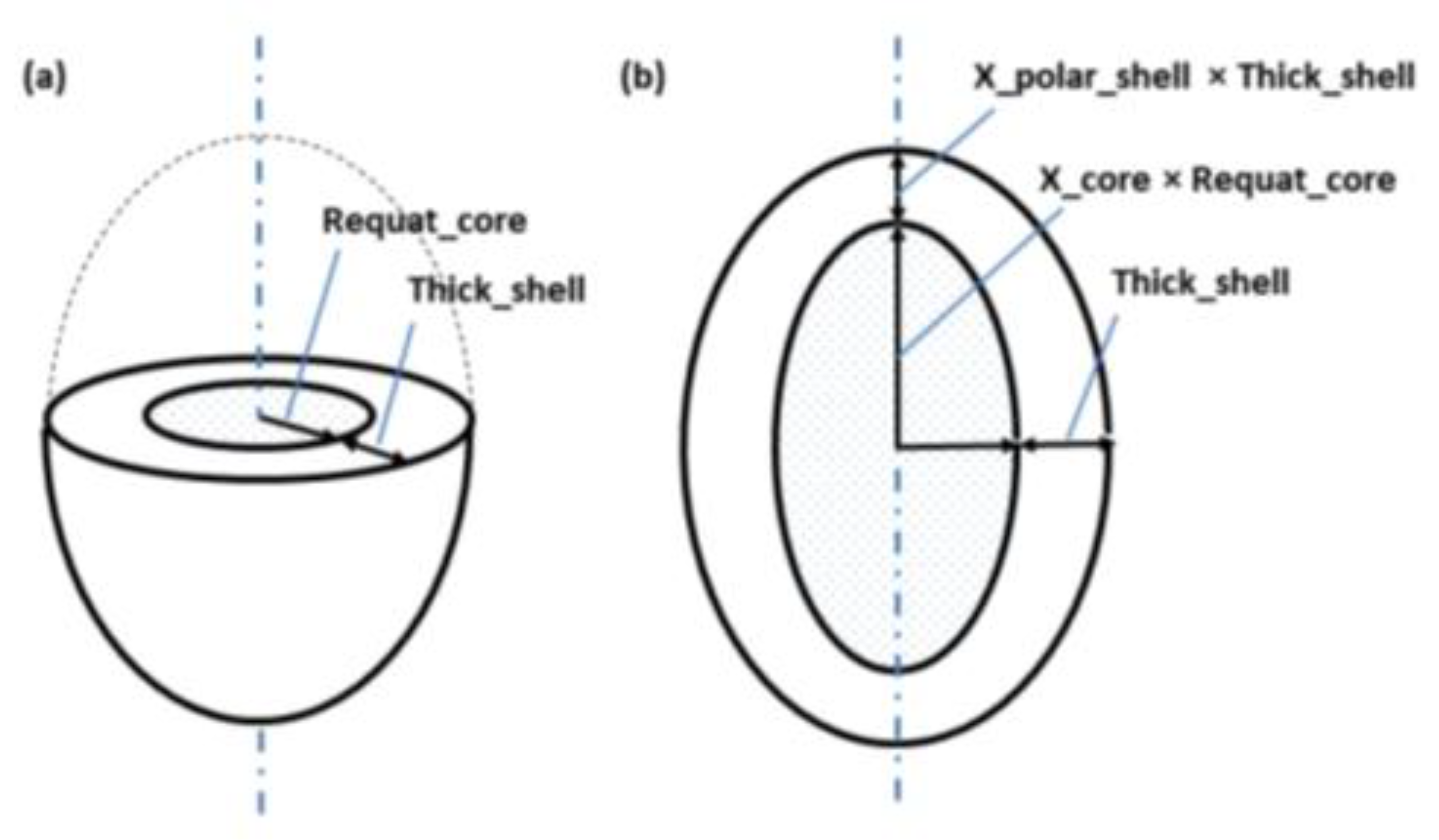
Figure 15.
The change in the length of the major axis with increasing annealing time.
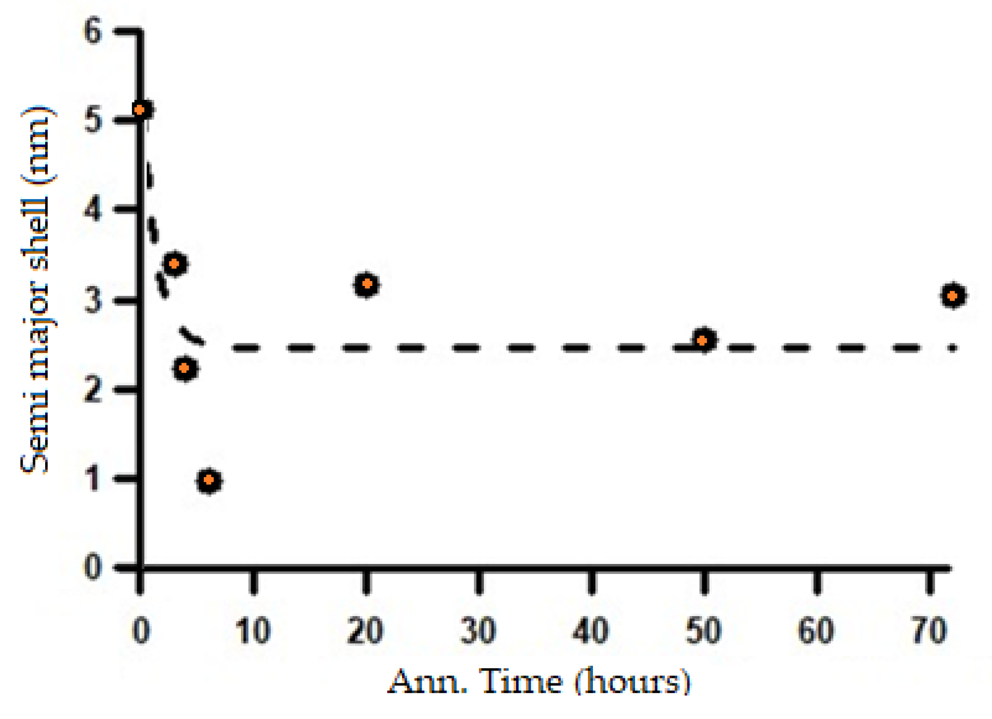
Figure 16.
The change in shell thickness corresponding to the increase in annealing time.
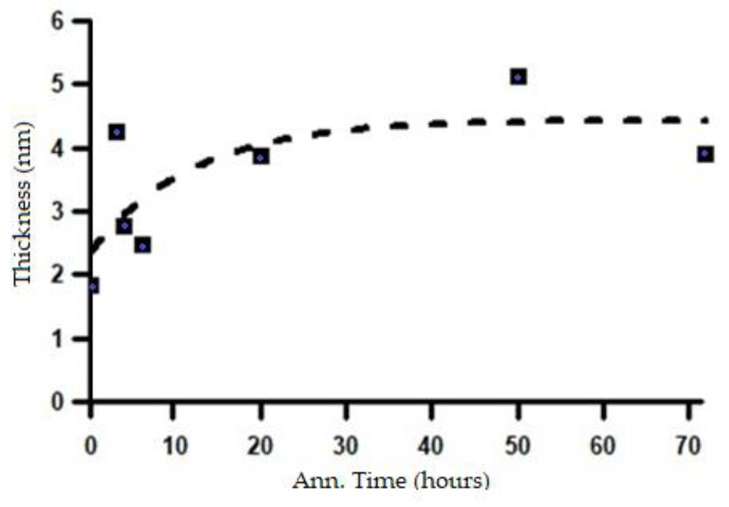
Figure 17.
Change in shell volume with increasing annealing time based on SAXS analysis using the ellipsoid core–shell model.
Figure 17.
Change in shell volume with increasing annealing time based on SAXS analysis using the ellipsoid core–shell model.
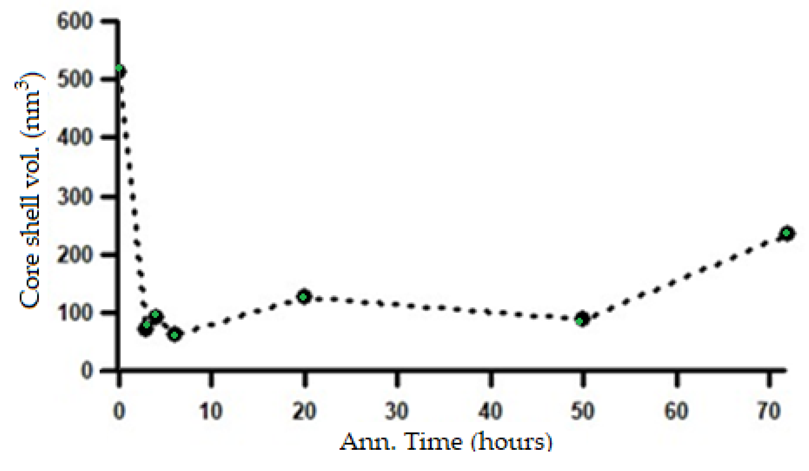
Figure 18.
Effect of percentage spheroidized pearlite on hardness value.
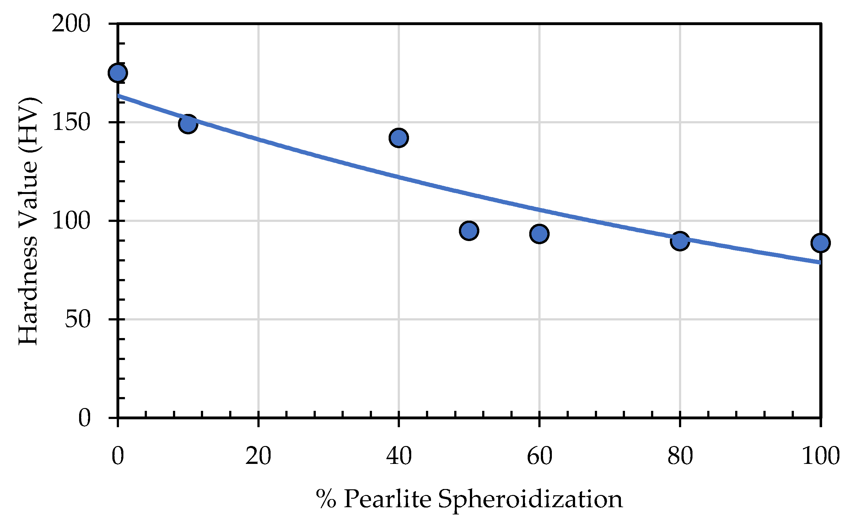
Figure 19.
Effect of percentage spheroidized pearlite on tensile strength.
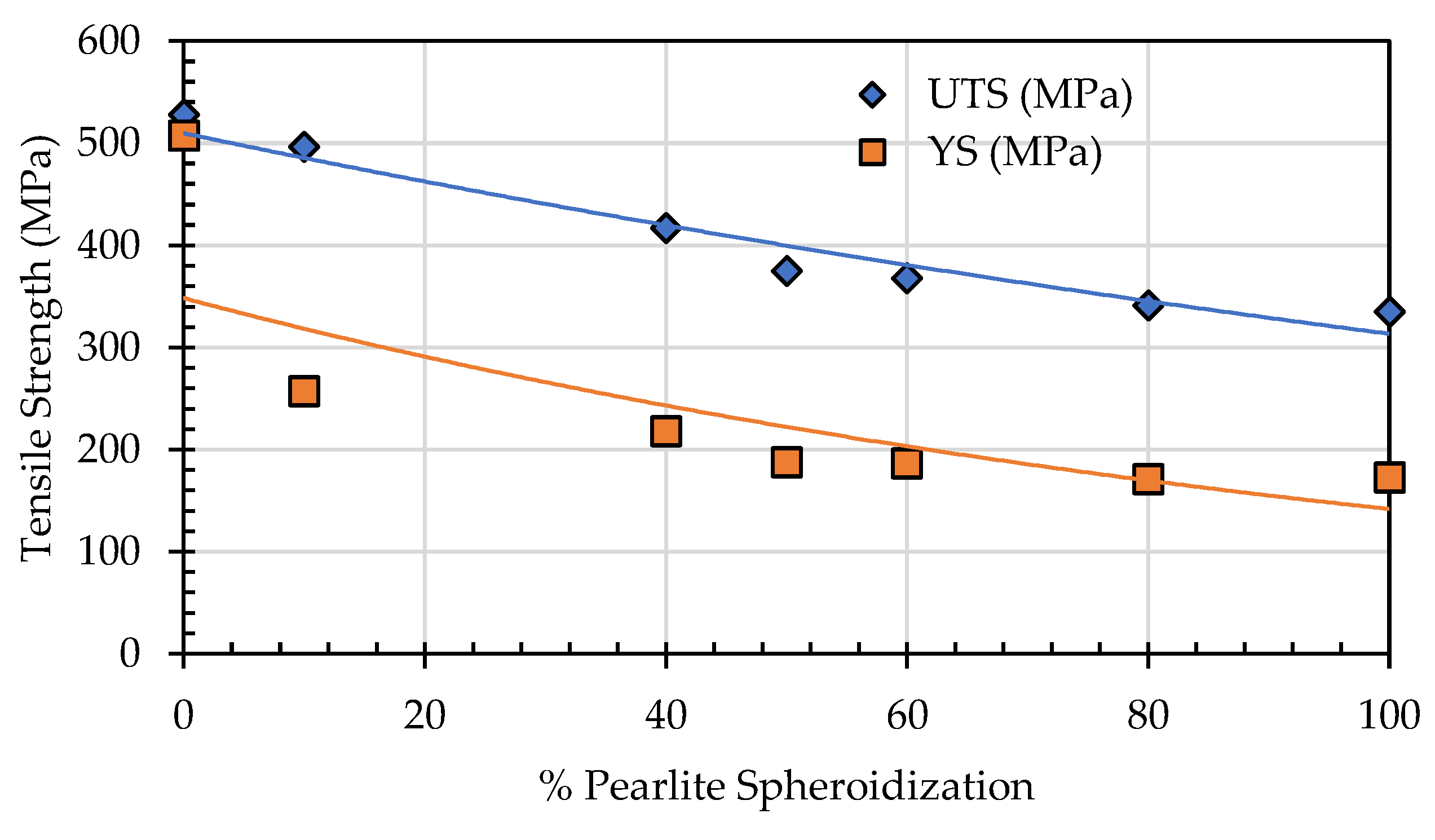
Figure 20.
Effect of annealing time on tensile strength of SA 178 materials.
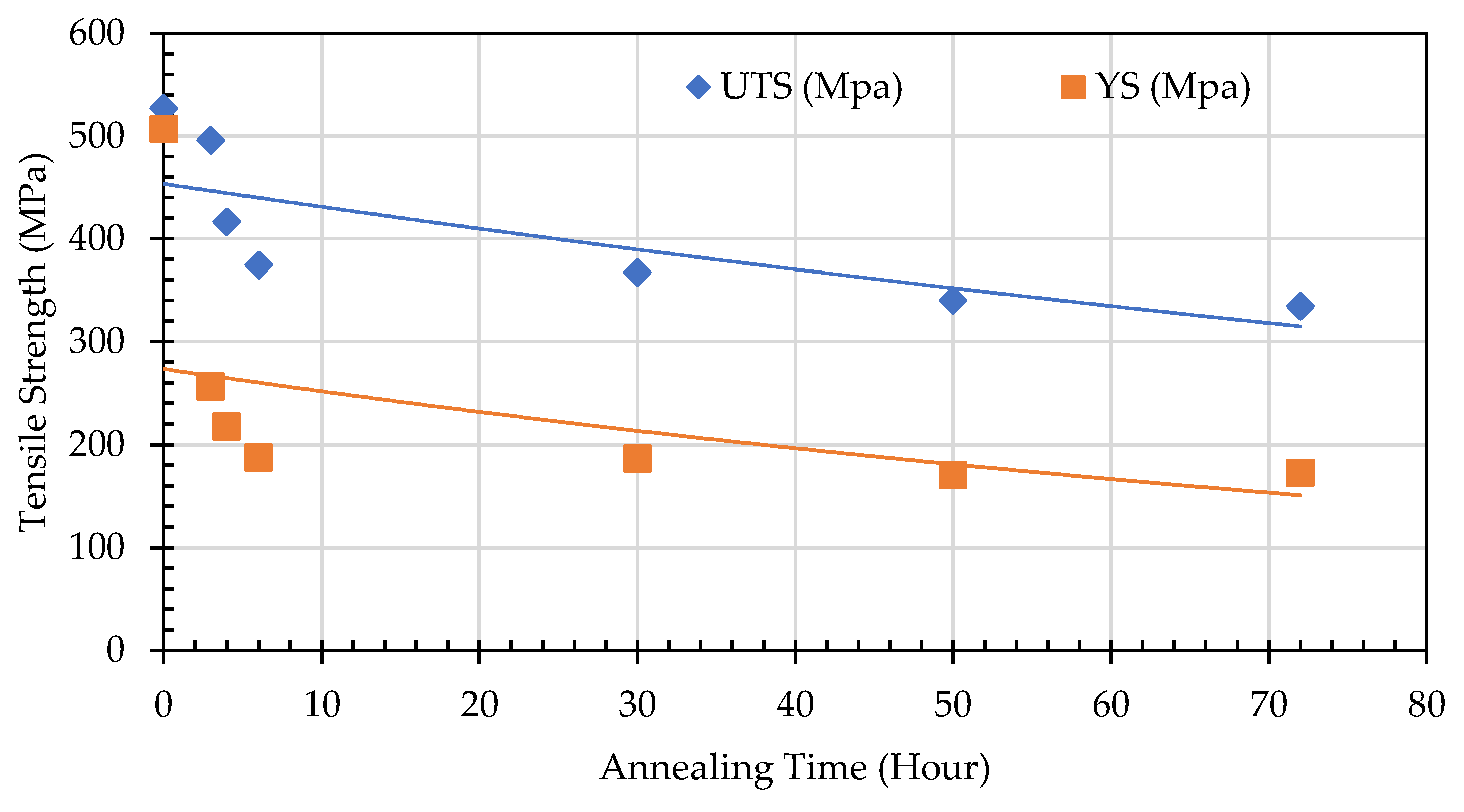
Figure 21.
Effect of pearlite spheroidization on elongation of SA 178 materials.
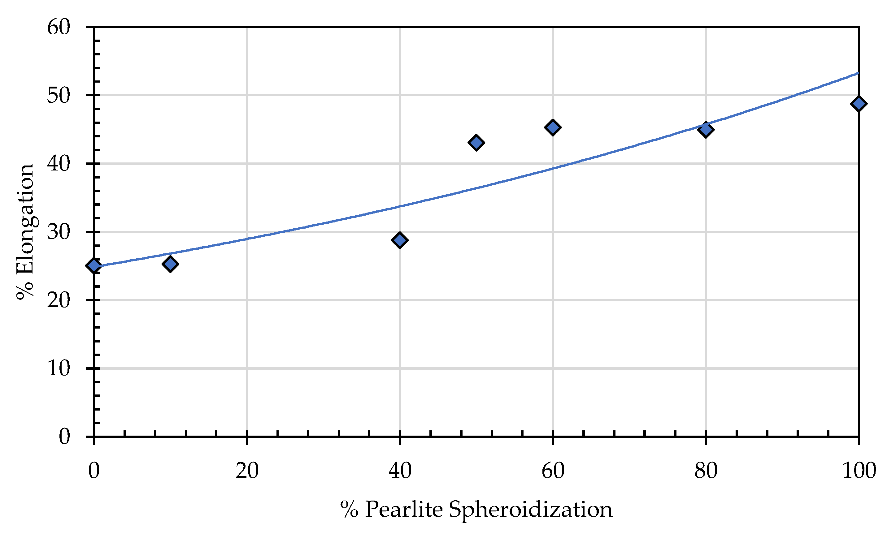
Figure 22.
Effect of Spheroidization Ratio (%) on ultimate tensile strength (MPa).
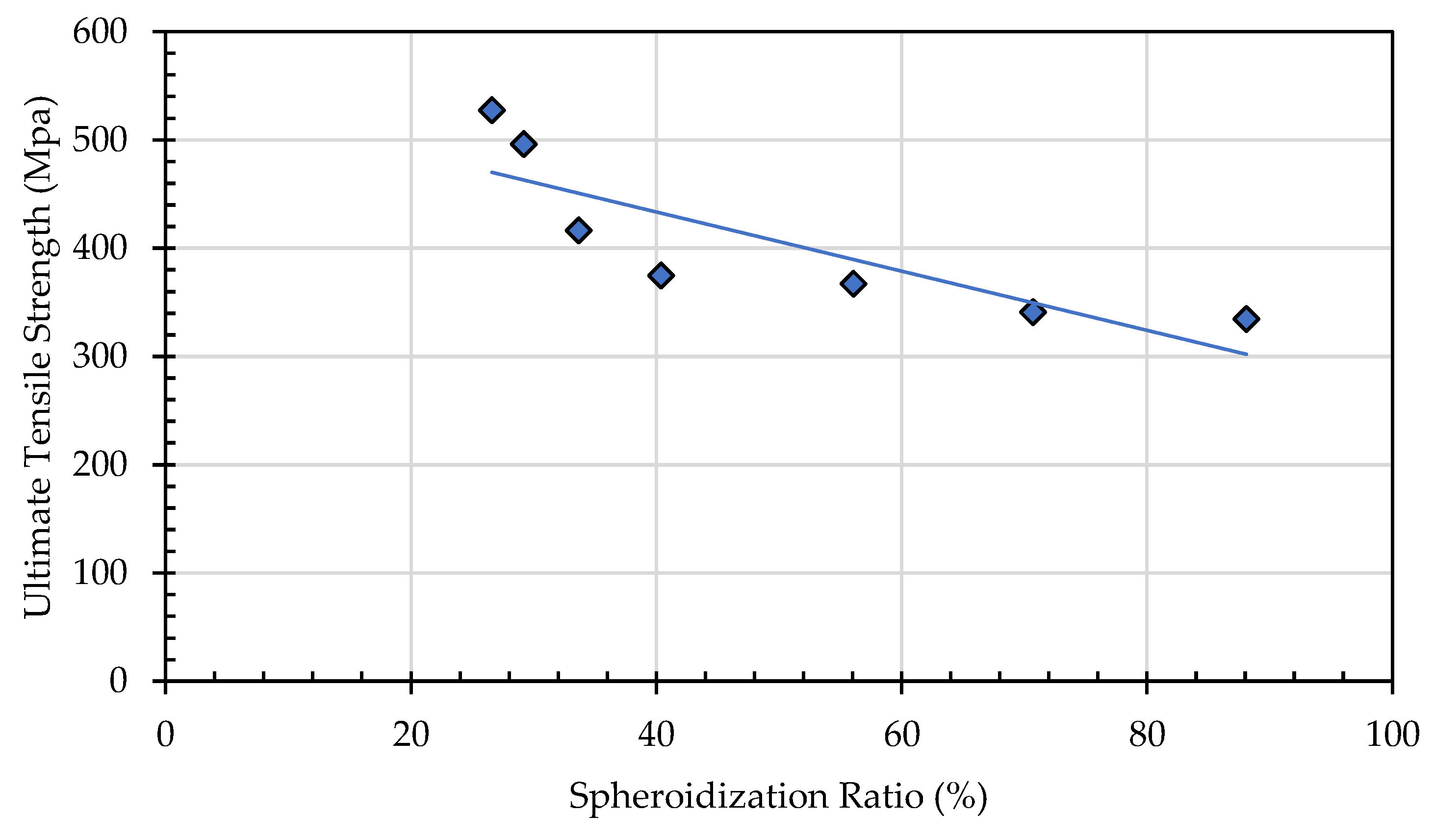

Table 1.
Chemical Composition of AISI SA 178 grade C.
| Element (wt%) |
C | Mn | P | S | Fe |
|---|---|---|---|---|---|
| Standard specification |
0.35 Max. | 0.80 Max. | 0.035 Max. | 0.035 Max. | Bal. |
| Test result | 0.184 | 0.452 | 0.0138 | 0.0051 | Bal. |
Table 2.
Temperature and time parameters for heat treatment to obtain spheroidized pearlite.
| Heating Temperature |
Holding Time (hours) | ||||
|---|---|---|---|---|---|
| 650 °C | 4 | 6 | 30 | 50 | 72 |
| 750 °C | 3 | 6 | 30 | 50 | - |
| Cooling | All of specimens are slow cooled (furnace cooling) | ||||
Table 3.
EDX result on particle that formed after heat treatment.
| Element | (wt%) |
|---|---|
| Fe | 67,55 ± 1,40 |
| C | 32,45 ± 0,39 |
Table 4.
Vickers Hardness Test Result.
| Spheridized Pearlite (%) |
0 | 10 | 40 | 50 | 60 | 80 | 100 |
| Hardness Value (HV) | 175 | 149 | 142 | 95 | 93 | 89 | 88 |
Disclaimer/Publisher’s Note: The statements, opinions and data contained in all publications are solely those of the individual author(s) and contributor(s) and not of MDPI and/or the editor(s). MDPI and/or the editor(s) disclaim responsibility for any injury to people or property resulting from any ideas, methods, instructions or products referred to in the content. |
© 2025 by the authors. Licensee MDPI, Basel, Switzerland. This article is an open access article distributed under the terms and conditions of the Creative Commons Attribution (CC BY) license (http://creativecommons.org/licenses/by/4.0/).
Copyright: This open access article is published under a Creative Commons CC BY 4.0 license, which permit the free download, distribution, and reuse, provided that the author and preprint are cited in any reuse.


