
Submitted:
16 December 2025
Posted:
18 December 2025
You are already at the latest version
Abstract
Aiming at continuum robots with high flexibility but poor stiffness, which limits its application in certain high-precision and high-load occasions, and the traditional method of changing stiffness has the problems of complicated structure, small range and slow response, etc., and this paper proposes a stiffness adjustment method based on Twisted Multi-String Actuators (hereinafter referred to as TSA) for bionic spine-like continuum robots. Firstly, a bionic spine-like configuration design is proposed to accommodate the variable stiffness method of the force-locking. Secondly, the proposed TSA variable stiffness method is theoretically analysed in terms of geometrical relationship and stiffness to provide a basis for constructing other mathematical models such as its string-twisted. Finally, an experimental prototype was constructed for flexibility testing, and then the experiments of the TSA variable stiffness method under the conditions of two/three/four-strand string were carried out to investigate the retraction and stiffness characteristics under different numbers of torsion turns and different loads, respectively. The results demonstrate that the stiffness of the robot increases with the TSA method, and the increase in the number of string strands improves the failure point of the robot, and the characteristic curves show that the design and model in this paper are more effective than the traditional force-locking design with single string. The design is simple, responsive and has a large adjustment range, which provides a reference value for the study of the stiffness of continuum robots.
Keywords:
continuum robot
; force-locking
; variable stiffness
; TSA
; spine-like
0. Introduction
Compared with rigid robots, continuum robots have unlimited degrees of freedom and flexibility of bending [1,2,3], and also smaller weight and size [4], so they have higher adaptability in small spaces [5], and can replace manual work in small, complex and dangerous spaces, such as in the inspection of aircraft intakes, nuclear inspection, restricted space welding, in-orbit tasks and medical tasks, etc. [6,7,8,9]. However, in general, the design of structures with large aspect ratios will also amplify the problem of low stiffness: in the case of continuum robots, the larger the aspect ratio, the worse the stiffness will be, making them unable to adapt to high-load tasks [10]. Further, the stiffness characteristics of continuum robots hinder their ability to operate under high load conditions with high stiffness for precise positioning and low stiffness for safe motions such as collision-free [11]. To overcome this drawback, it is therefore necessary to introduce a variable stiffness design for continuum robots so that their stiffness can be controlled in real-time with the task demands.
In the previous continuum research, researchers have focused on variable stiffness control using material-based methods, that is, the use of materials in different conditions of the phase transition to get different stiffness of the robot, such as the use of low-melting-point alloys, through the change of the temperature to control the state of the material [12] , but also through the characteristics of memory alloys, such as the current, the temperature and so on, by controlling shape memory alloys wrapped on the surface [13] or mounted on other components [14,15,16,17] to control the stiffness of the robot, but this method has obvious drawbacks: the response speed is too slow, making it inconvenient to adjust the stiffness, and part of the design exists media harmful to the human body and the environment, which is not suitable for all application scenarios [18] ; there is also the jamming structure, which achieves variable stiffness through jamming and is specifically divided into layer jamming and particle jamming [19,20,21] . Particle blocking is the process of locking the shape of particles by compressing them through negative air pressure, so that the particles change from a loose flow state at normal air pressure to a solidified state, thus increasing the stiffness. Layer blocking, on the other hand, improves stiffness by generating increased friction between layers to resist loads; as for the variable stiffness scheme from the structural design’s point of view, also called shape-locking, there is generally only one stiffness mode that can be adjusted, and there is no way to make continuous stiffness adjustments, so it can only be used for a specific mission objective, and there may also be problems with structures colliding with each other [22], or structures jamming on each other [23].
It is easy to see that, for the continuum, all of the above methods suffer, to varying degrees, from structural complexity, slow response, and hazardous or motion-affecting media. Therefore, this paper will focus on the force-locked variable stiffness method: it generally provides a larger friction force to the continuum using string, etc., to resist the load and increase the stiffness. However, for this method, the friction provided needs to be large to increase the friction of the continuum robot [24,25]. The traditional design starts with variable stiffness methods such as variable stretching with only a single rope, which cannot provide a large friction force, some variable stiffness mechanisms are not decoupled from the motion control mechanism, which increases the difficulty of control, and some studies are limited to single joints, which narrows down the advantages of the flexibility of the continuum robot. Further studies have shown that changing the design of the traditional force-locked variable stiffness device kind of only one wire rope stretch to provide tension, and introducing TSA, a variable stiffness method based on multi-stranded rope torsion, can regulate a wider range of stiffness [26].
In this paper, to overcome the shortcomings of previous force-locked variable stiffness methods [27], a spine-like continuum configuration is first proposed, which is designed with a hollow structure at the base of the configuration and improves the problem of slippage that the continuum of the previous configurations is prone to, and the characteristics of its configuration make it more adaptable to the force-locked variable stiffness method. Using the above configuration, a force-locked variable stiffness method based on the torsion of multi-strand ropes is proposed, whose stiffness can be continuously and quickly adjusted to the robot’s stiffness by the torsion of multi-strand ropes on the axis. Secondly, the stiffness model of the robot and the theoretical model of the multi-stranded rope are discussed. Finally, the robot was assembled, and the robot motion flexibility experiment was completed to verify the feasibility of the mechanism; the experiment of rope retraction and motor angle was completed to determine the control relationship; under the condition of the number of strands of multi-stranded ropes, n=2, n=3 and n=4, the stiffness experiment was carried out on the robot under the condition of different tension force and the number of rotating motor laps; the results of the above experiments have proved that the principle and model proposed in this paper is effective and the assembled objects can be used for the robot. The above experimental results prove that the principle and model proposed in this paper are effective, and the assembly object can provide a reference for the stiffness of the continuum robot.
1. Matrix Structure Design
Conventional robots are not flexible enough to adapt to complex environments, and continuum robots are more flexible, but they cannot meet the load and accuracy requirements. Therefore, the variable stiffness control of continuum robots has emerged. Therefore, this paper proposes a spine-like configuration of the substrate design, so that it is more suitable for the force-locked variable stiffness method, followed by the use of TSA for the robot to perform force-locked variable stiffness control. However, the contraction of the multi-stranded rope is more obvious after the execution of rope torsional stiffening [28], and the length of the continuum is not changeable, resulting in a conflict between the continuum and the multi-stranded rope’s retraction [29], therefore, a retraction mechanism is proposed based on the spine-mimicking configuration [30], so that it can be adapted to the length contraction of the robot due to the TSA.
1.1. Spine-like Structure Design
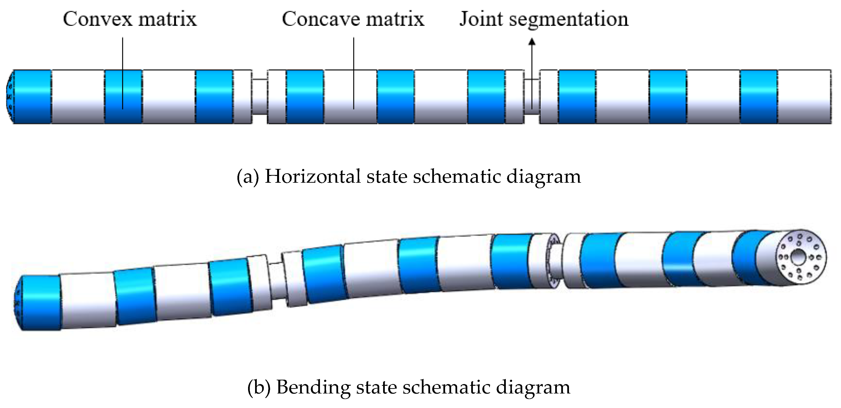
The robot with a spine-like configuration described in this paper starts from the principle of bionics. A concave-convex-concave contact substrate with spherical contact is designed according to the vertebrae-disc-vertebrae configuration of the spine. This matrix increases the friction by changing the line contact to a spherical contact compared to the conventional force-locking configuration.
As shown in Figure 1(b) is the schematic diagram of the three bases (concave-convex-concave) of the robot, the robot adopts two types of substrates: ‘concave’ and ‘convex’ (see Figure 2). Their working principle is as follows: the motion of the substrates (and thus the entire continuum robot) is controlled by wire ropes passing through rope holes distributed circumferentially near the outer side; sensor signal lines pass through rope holes distributed circumferentially near the inner side. The two substrates work as follows: the motion of the substrate is controlled by the wire rope passing through the rope holes distributed in the circumference near the outside, thus controlling the overall motion of the continuum robot; the sensor signal wires are passed through the rope holes distributed in the circumference near the inside. The hollow rope holes are the key to the force-locking mechanism: the multi-stranded ropes responsible for regulating the robot’s stiffness pass through the middle rope holes and are twisted by the variable stiffness motors to provide different tension forces to control the robot’s stiffness. For ease of identification, the “concave” matrix is labelled in grey and the “convex” matrix in blue.
Each substrate has nine rope holes distributed evenly around the circumference. Three holes at 120° intervals are responsible for controlling a continuum joint with two degrees of freedom, “pitch” and “yaw”. The continuum robot is designed with three joints and six degrees of freedom, providing ample application space.
Due to the multi-substrate mechanism, the TSA variable stiffness design principle of the continuum robot is to change the pressure between the substrates through the tightening and loosening of the multi-stranded ropes in the intermediate rope holes, thus changing the friction between the substrates, and using this friction to resist external loads and deformations, thus changing the flexibility and stiffness of the robot. At the same time, the substrate structure also implies the need to fix the robot arm through the end of the drive rope and the front end of the drive box link, so that the substrates are closely fitted to each other and can only rotate along the contact sphere. Therefore, the length of a single substrate will also affect the number of substrates, and thus the joint angles, pressure transfer and other parameters of a continuum robot, for a certain overall length design index [28]. In this paper, the length of the individual substrate is 15 mm for the “concave” type and 20 mm for the “convex” type, with a radius of 5 mm and a total length of 300 mm.
Figure 3.
Model of three-joint continuum.
The joints of the spine-like continuum prepared using resin material are shown in Figure 4. The continuum’s joints are composed of substrates: six form the first joint (from the right), six form the second joint, and five form the third joint, and the “convex” substrate for the third joint is chosen for the convenience of the subsequent end-equipment retrofitting. The black matrix at the joint division is a “concave” matrix with an outer circle removed from the middle part, which is used to fix the driving rope and can better distinguish the joints.
1.2. Rollback
Force-locking mechanisms that take a single rope tend to stiffen the continuum by adjusting the rope tension. In the case of only a single rope, due to the low tension, there is no situation where the variable stiffness rope length decreases due to the tension, thus driving the continuum back. However, in the case of TSA, the multi-stranded rope shrinks more and provides a larger range of variable stiffness, which can cause the continuum to back out. Further, when there exists a retraction situation, the variable stiffness operation cannot be realised because the continuum is usually fixed to the box, which leads to motion conflicts. Therefore, there is a need to design a retraction mechanism that can be used for TSA variable stiffness based on the spine-like continuum robot proposed in this paper.
The structure of the return mechanism is shown in Figure 5, which mainly consists of a sleeve and a slider. A section of the sleeve is embedded in the continuum structure, and the other end cooperates with the slider and slides through the four grooves arranged in the circumference of the sleeve. The sleeve is linked to the drive box. The motion principle of the retraction mechanism is shown in Figure 6. When the multi-stranded rope is twisted to provide a certain stiffness for the continuum, the multi-stranded rope through the middle rope hole will contract, thus driving the continuum back. At this time, the bolts at both ends of the slider linked to the drive box will be relaxed, so that it can obtain the freedom of sliding along the sleeve, and the retracted continuum will drive the slider to move, to realise the retraction of the continuum with the variable stiffness multi-stranded rope after the twisting of the multi-stranded rope. After the retraction is completed, the bolts linked to the drive box body are re-fixed to ensure its positioning.
As described in the design section, the spine-like structure is proposed to provide resistance to displacement for the robot variable stiffness from the perspective of friction; and the retraction mechanism is proposed to ensure that the rope-driven retraction displacement does not conflict with the structure when the robot performs the variable stiffness operation. The combination of the two ensures that the variable stiffness operation described in this paper is carried out smoothly.
2. Geometric Model Research
2.1. Geometric Model of String Twisting
TSA due to the existence of torsional motion, compared with general variable stiffness methods, its model analysis requires constructing mathematical models starting from the untwisted cylinder to analyse the geometric changes in the relationship between its length and other quantities, the specific structure is shown in Figure 7. Where L0 is the original length of the rope, R0 is the original diameter of the rope, r0 is the original radius of the rope, T is the tension on the rope, Mmotor is the tension provided by the motor, ΔL is the amount of change in the length of the rope after torsion, Ltwisted is the new length of the rope after torsion, and Fstring is the force that resists deformation after the deformation of the rope.
When the rope is twisted by θ its cylindrical expansion is shown in Figure 8, and the colours of the sides of the right triangle constructed in the geometric relationship diagram correspond to the sides in the above diagram. The length of the rope after twisting can be derived as follows:
However, in the force-locked twisting of a multi-stranded rope, after twisting at a certain angle, its radius cannot be the same as the traditional cylindrical model with the default radius unchanged. Rather, after twisting, and shortening a certain length, the diameter will increase to Rtwisted, and its post-twisting schematic is shown in Figure 9 for the post-twisting diameter. It can be assumed that the volume of the rope remains constant during twisting [31], i.e.,:
It is not difficult to derive the mathematical relationship between the radius rtwisted after twisting and the initial radius r0 from the cylinder formula:
Therefore, the conventional unfolding model of Figure 7 can be modified after taking into account the nonlinear increase of the rope radius produced by torsion. After torsion θ, the change in rope length ΔL can be calculated by the following equation:
Further, it can be derived that after twisting, the helix angle α produced on the rope is:
However, this paper found in the actual research, based on the equal volume assumption of Equation (2), in the case of multi-stranded ropes, due to the large gap in the multi-stranded ropes, as shown in Figure 10, in the process of torsion, the behaviour of the TSA will be to fill in the gap first in the uniform torsion, resulting in the more the number of rope strands, the greater the error in the calculation of Equation (4) is calculated and is not applicable to the method of multi-stranded ropes with continuous body locking as described in this paper. In this paper, from the energy point of view, to establish the expression applicable to this robot. The shaded portion of the figure shows the much considered gap under the assumption of equal volume.
Since this paper only investigates the case under equilibrium conditions, it follows that when the TSA is not loaded, the total input is provided by the motor torque Mmotor, which leads to a certain amount of elastic force in the rope after twisting. Therefore, the formula for Δl is proposed as follows in Equation (6):
Where k is the elasticity coefficient of the material used and rtwisted is easier to measure compared to Δl, therefore, in this paper, the validity of the above equation will be verified experimentally.
2.2. Analyses of Variable-Stiffness
The variable stiffness structure of the robot is a core component and one of the design goals of this robot. The variable stiffness design proposed in this article, as mentioned earlier, uses TSA to control the motor and twist the multi-rope connected to it, causing axial tension T to be generated on the multi-strand rope passing through the central axis of the robot, thereby increasing the pressure N between the substrates and changing the frictional force used to resist external loads, ultimately causing a change in the stiffness of the robot. The principle is shown in Figure 11.
The black solid line represents the entire continuum, the black dashed line represents the continuum matrix, and the blue solid line represents the driving rope. From the figure, it can be seen that the end of the robot is a continuous free end, used to perform continuous motion and medical functions. The front end is fixed at the connection on the support plate. Therefore, when conducting mechanical or stiffness analysis, the continuous part of the robot can be regarded as a cantilever beam structure.
As shown in Figure 11 (a), the robot is not performing variable stiffness operation at this time. After being subjected to the end radial load F, the flexible joints of the robot are composed of discrete matrix cascades. When the joint itself is not subjected to axial tension, it does not have radial stiffness and cannot resist the end load. Therefore, under the action of the load, there will be a displacement D in the radial direction and a rotation angle θ will be generated; When the robot performs TSA variable stiffness operation, as shown in Figure 11(b), the discrete joints of the robot are squeezed against each other, becoming rigid joints as a whole to resist deformation. In more detail, the TSA motor of the variable stiffness section rotates N turns, driving the connected multi strand ropes to twist and generate axial tension force T, completing the TSA process. At this time, under the action of tension force T, the substrates are squeezed against each other, generating axial pressure N. Under the action of external radial load, the robot will have a radial movement trend. Therefore, under the action of the pressure N between the substrates, friction force between the substrates will be generated in the radial direction, which is opposite to the direction of the external load F, and stiffness will be obtained to resist the external radial load F, thus completing the variable stiffness process. Furthermore, when the external load F exceeds the maximum frictional force fmax obtained by the TSA process, static friction between the substrates will be converted into dynamic friction, and slip will begin to occur. At this point, the robot cannot be considered to have failed; When the substrate slips completely, the robot’s motion can no longer be controlled, and the robot is considered to have failed. The external load at this point is referred to as the failure point of the robot. In actual use, it should be kept within the maximum static friction force fmax range, and should be avoided as much as possible from being used within the maximum static friction force and failure point, rather than continuing to be used after the failure point.
The stiffness of the continuum consists of two parts: radial stiffness and axial stiffness. However, in the axial direction, the horizontal displacement of the continuum is limited by the support plate and the variable stiffness retraction mechanism. The stiffness is determined by the strength of the base material and support plate. In practical operation, medical devices mainly cause loads in the radial direction, so discussing axial stiffness is meaningless. The continuous matrix itself does not have radial stiffness due to its discrete structure, and its stiffness is provided by the frictional force generated by the pressure between the matrices. Furthermore, the two main sources of tension on the robot substrate are the tension generated on the drive rope located on the circumference and the tension generated on the multi strand rope located on the axis used by TSA. Therefore, the stiffness K of the robot mainly comes from two sources: one is generated by the driving rope and cannot be adjusted; The second is the variable stiffness of the robot generated by TSA, which is provided by tension and serves as the main stiffness for the robot’s load tasks.
The cantilever beam model of the robot is shown in Figure 12. Under the radial action of external force F, the robot generates displacement D and rotation angle θ. The blue solid line represents the driving rope and the red rope represents the TSA rope, which bring tension forces in two axial directions, thereby generating pressure between the substrates to obtain the friction force between the substrates. The friction force is converted into a friction torque Mf fixed on the continuous cantilever beam. At this point, the steel wire rope being stretched can be equivalent to a spring. According to the formula for calculating the stiffness of a cantilever beam, the stiffness of a continuous body can be calculated using Equations (7) and (8).
The stiffness of the continuum is derived from the driving force Fd when the tension force T of the multi-rope is 0 without TSA operation, which generates the original stiffness K0 of the robot and the variable stiffness Kt of the continuum when T ≠ 0. Therefore, first use Hooke’s law to calculate the robot’s own stiffness K as shown in Equation (9). For the safe operation of medical robots, it should be assumed that the robot bends to the most extreme situation, where only one driving rope is subjected to force Fd. At this point, the original stiffness K of the robot is the lowest.
According to geometric relationships, the relationship between joint angle θ and end displacement D can be derived as follows:
Where Ebase is the equivalent modulus of elasticity of the base, and Ibase is the equivalent base moment of inertia around the axis, under the condition that the whole is regarded as a cylindrical cantilever beam, the holes of the driving rope and the holes of the tensioning rope are symmetrical around the axis. The cross-section area of the base is Abase; the area occupied by the drive rope on the circumference is Adrive; the area occupied by the tension rope hole on the axis is Atension; the area occupied by the rope hole reserved for the sensor on the circumference is Asensor, then the actual cross-section area A is:
The cross-sectional shape of the base is shown in Figure 13, from which Ibase can be deduced as the following equation:
For the assumed state at this time, the force distribution between the substrates is shown in Figure 14.
“Convex” type matrix as an example (“concave” configuration of the same force), its equilibrium by the radial load F, by the fixed tension on the drive rope F drive and the tension rope on the adjustable tension T tension under the action of reaction Pressure N, and then the friction torque Mf produced by N under the joint action to maintain balance, can be obtained as follows.
Where, according to the principle of tribology, under the condition of no failure of the substrate, i.e., the condition of maximum static friction, Mf is maximised as in the following equation, with the direction being upwards.
Thus the stiffness K0 of the robot at this point can be obtained as Equation (15). In the formula, is the total distance from the end of each section of the substrate to the point of static friction force
According to the assumption, the robot does not adjust its stiffness at this time, resulting in the minimum stiffness.
After the robot performs TSA variable stiffness operation, the tension force T on the axis of the continuum is not 0. The principle of variable stiffness should be discussed in two situations, that is, the robot only has a motion trend, and there is only static friction between the substrates at this time; When the static friction force exceeds the maximum value, slip has occurred between the robot substrates, but the overall failure has not yet occurred. Both of the above situations will ultimately maintain force balance, therefore, the matrix force diagram at this time is shown in Figure 15.
From the figure, it can be seen that the difference between the stress state of the substrate at this time and the stress state at T=0 is that the inter substrate pressure N is jointly provided by the force Fdrive on the driving rope and the force T on the TSA wire.
In the first situation, where static friction is still maintained between the substrates and there is only a relative motion trend without any relative motion, the schematic diagram is shown in Figure 16.
Thus the stiffness Krobot of the robot at this point can be obtained as:
In the second situation, where the external load exceeds the maximum static friction force but has not reached the failure point, and a part of the continuum rotates, it is assumed that the robot only has one joint l1. In this joint, under the action of an external load F, the base of the lm joint rotates while the base of the lj joint remains unchanged. The continuum rotates a total of θ angles and undergoes a displacement of Dtension1, as shown in Figure 17.
For the variable stiffness Ktension, the following two systems of equations can be listed according to their mechanical equilibrium:
For its geometrical relations, the following relation can be obtained
At this time, the force on the driving rope and TSA rope are jointly provided. Therefore, force can be calculated by Hooke’s law:
By combining Equations (16)–(20), the expression for the external load F can be obtained. And the load F on the second, third, and first joints, the driving rope force Fdrvie, and the tension rope force T are the same, the joint length is different from l1, and the other mechanical states are similar. The load F on them can be deduced by the above method, and the corresponding Dtension2 and Dtension3 can be calculated. Therefore, the overall stiffness Ktension of the robot is given by Equation (21):
For a section of the matrix, the point of action of the matrix friction torque Mf is at the end of the matrix, while for the entire continuum, the point of action of the friction torque is at the fixed end. Therefore, the total friction torque on a joint is expressed by Equation (22).
Among them, is the total distance from the end of each base to the point of static friction force. There are two configurations of the matrix described in this article, therefore, two situations need to be discussed for ls Equation (23):
Based on the above two friction conditions and calculation formulas, the stiffness of the robot should be calculated using the following two scenarios Equation (24):
It is not difficult to find from the above calculation process that the stiffness K of the robot is small without considering the tension between the substrates, while when considering the static friction force formula, the stiffness calculation formula is greatly affected by the tension force and the driving rope force. Furthermore, the force on the driving rope cannot be adjusted and is provided by the motor. Its value is significantly smaller than the force on the tensioning rope. Therefore, the force provided on the TSA rope will have a significant impact on the variable stiffness performance.
2.3. Geometric Model of Turning Angle
After the study of the variable stiffness principle of the robot, to ensure that the motion of the matrix of the continuum robot does not fail, it is necessary to analyse the motion angle of the matrix of the continuum. From the above robot’s matrix configuration, it can be seen that the motion limitation of the robot described in this paper will occur after the two sections of the matrix are rotated to a certain angle, the aperture wall of the drive rope or tension rope will be extruded with the drive rope or tension rope, and the matrix can no longer be rotated in the direction of the extrusion once one of the aperture walls has been extruded with the steel wire rope in that channel, and because the aperture diameter of the aperture of the tension rope is larger compared to the aperture diameter of the aperture of the drive rope and the angular change on the centre line is small [33], so only the angular limitation of the movement of the drive rope needs to be considered, and the above limit cases are shown in Figure 18.
Where Rrope denotes the diameter of the rope; Rdrive denotes the diameter of the hole of the drive rope; Rtension denotes the diameter of the hole of the tension rope; rcontact denotes the radius of the circular arc of the contact surface; R denotes the diameter of the substrate; l denotes the length of the substrate (excluding the circular arc portion); lcontact denotes the length of the circular arc portion of the substrate; θconcave denotes the limiting angle of the “concave-convex” contact; θ(convex) denotes the limiting angle of the “convex-concave” contact; and θ(convex) denotes the limiting angle of the “convex-concave” contact. )denotes the limiting angle of “concave-convex” contact; θconvex denotes the limiting angle of “convex-concave” contact. Therefore, from the geometrical relationship, the expressions for the two limiting angles can be deduced as follows:
From the above calculations, the robot described in this paper has a turning angle of θconcave ≈ 13°, θconvex ≈ 11°. The turn angle range of each joint is about 70°, which ensures that its flexibility can meet the basic task needs.
3. Experiment
3.1. Prototype Assembly and Feasibility Experiment of Motion
After theoretical modelling, the type of rope used in the TSA should be selected for the TSA variable stiffness continuum robot proposed in this paper. There are many different types of ropes available, mostly made of many different materials or combinations of materials (Vectran, Kevlar, Dyneema, etc.), with a wide range of radii, as well as braided and non-braided constructions, etc. In particular, Vectran ropes have a higher stiffness coefficient, which makes them more rigid for the TSA. Among these, Vectran ropes have a higher stiffness coefficient, which allows the rope to respond faster to torsion and thus better meet the experimental demands [34]. Considering that the Vectran rope may rupture under a load greater than 20N, a load of 0-10N is chosen in this paper. The robot experiment platform assembled in this paper is shown in Figure 19, which is mainly composed of the robot part, drive part, upper computer and sensor detection part.
The multi-strand rope TSA control motor described in this paper is the basis of variable stiffness, and its specific structure is shown in Figure 20, and its working principle is as follows: n-strand rope (yellow rope in the physical picture, n for the number of rope strands) one end by fixed in the coupling, the other end is fixed in the end of the continuum, coupling with the motor link, the motor rotates, due to the other fixation, the n-strand rope will twist and shorten, at this time to relax the linking bolts, so that the block can be back, and then tighten the bolt, using the self-locking of the motor and the bolt to fix the twisting of the n-strand rope, to complete the multi-strand rope TSA variable stiffness control process described in this paper.
The continuum control mechanism described in this paper is as follows: the control board is controlled from the host computer, and then the motor is driven by the driver, which drives the drive rope, thus controlling the movement of the continuum. The drive part of the motor is shown in Figure 21.
Subsequently, the motion control of the proposed continuum robot was verified using the above control principles, and the results are shown in Figure 22, demonstrating the robot’s ability to move in all directions.
3.2. Experiment on the Relationship Between Motor Rotation and Wire Retraction in TSA
After verifying the feasibility of the robot’s motion and ensuring its flexibility, the amount of rope retraction needs to be tested. More specifically, during the TSA process, as the number of motor torsion turns N increases, the rope used for actuation is “tightened” and there are two physical changes: a shortening of the rope length by ΔL and an increase in its diameter. This results in a significant increase in the stiffness and load capacity of the TSA [35]. The robot described in this paper will be affected by its ΔL, but the radius change will not be affected because the pre-drilled holes in the TSA located at the centre of the shaft reserve enough radius. The above characteristics of the TSA actuator, on the other hand, are highly variable due to the influence of the rope material and so on. Therefore, experimental verification of Equation (4) and (6) described in the previous section is needed to determine the robot’s length retraction ΔL after motor rotation N to ensure the robot’s manoeuvrability. The experimental setup is shown in Figure 23. below.
Using the experimental setup described in the above figure, for the number of rope strands n=2 and n=3, the motor was initially set to N=0 revolutions (no rotation), and the amount of backlash ΔL in the above figure was measured, and each time it was loaded so that N was increased by 5 up to N=30, while subject to the motor torque, with the number of rope strands n=4, N was increased by 1 at a time, up to N=17. A graphical comparison of the experimental data and the theoretical data is shown in the following Figure 24.
In the figure, the coordinate points are the actual experimental data, the dashed line is the theoretical curve based on the volume assumption, while the solid line is the theoretical curve based on the energy assumption. From the above figure, it can be seen that the expression for the amount of backlash of multi-stranded rope TSA proposed in this paper, which is based on Vectran from the principle of virtual work, is generally fitted to the actual situation when the number of motor rotating turns is small and is basically similar to that fitted to the traditional assumption based on the assumption of volume equivalence, but when the number of torsional turns is larger, it is fitted to the actual situation in a much closer way and is significantly superior to that based on the relational equation of the assumption of volume. This is due to the TSA in the multi-stranded rope case, the gap is larger, the assumption of volume equivalence has a certain error: In the motor rotation circle N is small, multi-stranded rope due to the larger gap, the transfer of torsion there is a hysteresis and lead to inhomogeneity, so with the theoretical formula fit is worse; and in the multi-stranded rope torsion is larger after the larger gap is filled by the deformation of the rope, the volume change is larger, which leads to the volume-based assumption of the fallback Volume calculation is no longer close to the real situation, and from the energy point of view, the use of virtual work principle of the calculation of the formula fit better; furthermore, based on the energy assumption of the relationship between the formula also exists in friction and other errors, and with the gradual approach to the limit torque of the motor, the greater the error; it is worth noting that, the two theoretical curves in the amount of retreat for about 20mm when intersected, this is due to the motor at this time, most of the work used for the torsion, and at this time the torsion is more uniform, the gap is smaller. Therefore, it can be concluded that the retraction equation proposed in this paper can better fit the retraction of the TSA under multi-stranded ropes, which can make the robot described in this paper obtain better operability.
3.3. Variable Stiffness Experiment Based on TSA
The stiffness characteristics of the robot are important in the study of this paper, so the continuum robot stiffness experiment is needed. The stiffness cannot be measured directly due to the limitation of conditions. However, by the cantilever beam stiffness formula, the displacement is inversely proportional to the stiffness, i.e., the end of the robot under a certain load, the smaller the displacement, the greater the stiffness, so it can be used to replace the robot stiffness by the robot end displacement D. The experimental setup is shown in Figure 25 below, where weights are tied at the end as the external load F, and the number of weights at the end is changed to change the load F. The increase in tension T is realised by the number of rotations of the motor n (i.e., the TSA achieves different degrees of torsion under the control of the motor) and is measured by the dynamometer, and the number of strands of the multi-stranded rope is taken as n=2,n=3 and n=4 for the three types of multi-stranded ropes of the same material but with different strands. At the end, an increasing load F is taken and the displacement is recorded to respond to the displacement-angle-load characteristics and to verify that the stiffness becomes higher as the number of strands increases and the tension increases.
By the above experimental procedure, the experiment was first carried out at n=2 and n=3, with the number of motor rotations N=10, N=20 and N=30, respectively, by loading the end of the motor at intervals of 0.5N starting from F=0N and measuring the displacement D and the tension T of the rope, until the robot fails. After that, the above experimental procedure was repeated for n=4 for the number of motor rotations N=5, N=10 and N=15 respectively, and the experimental results are shown in Figure 26.
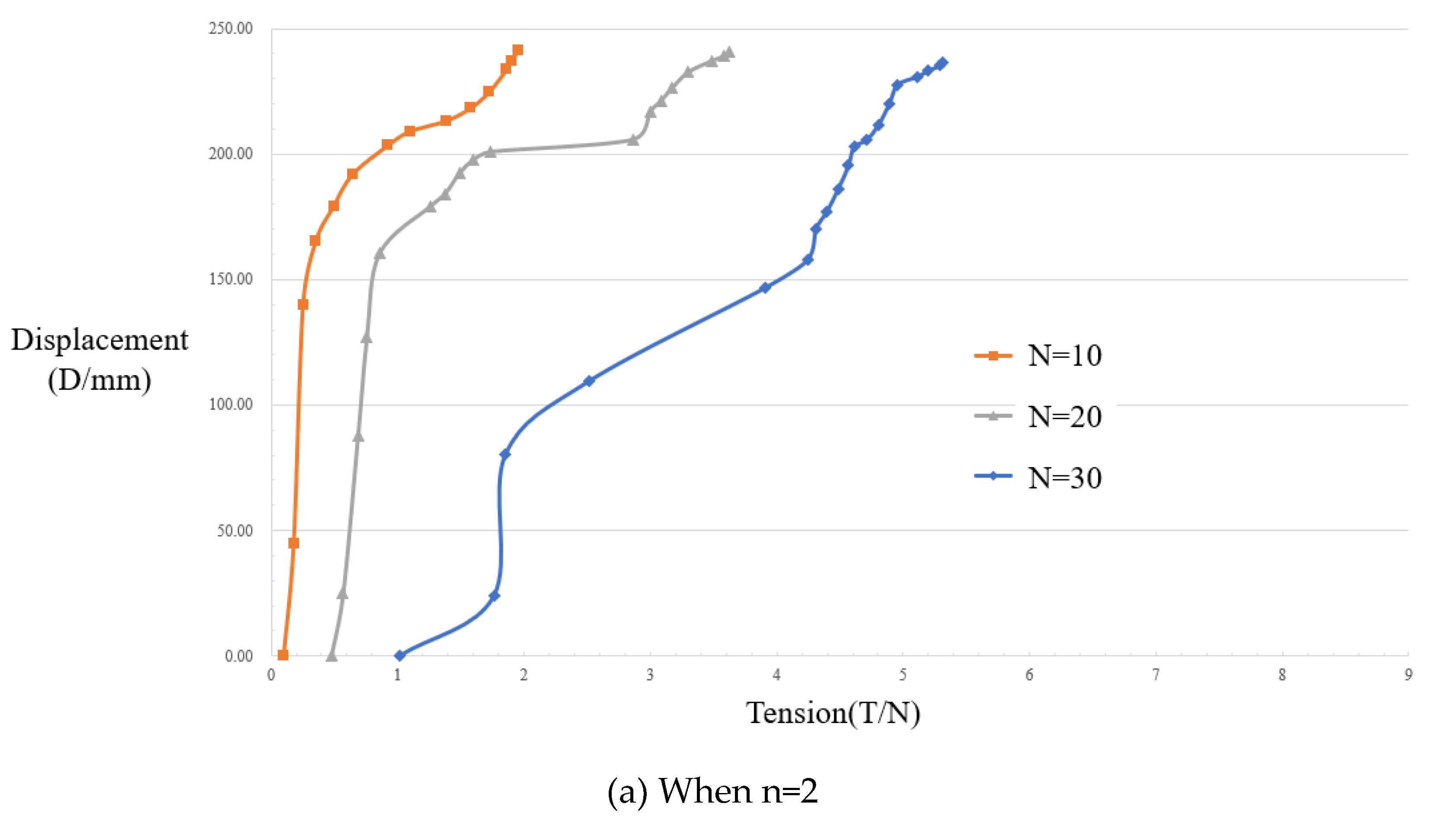
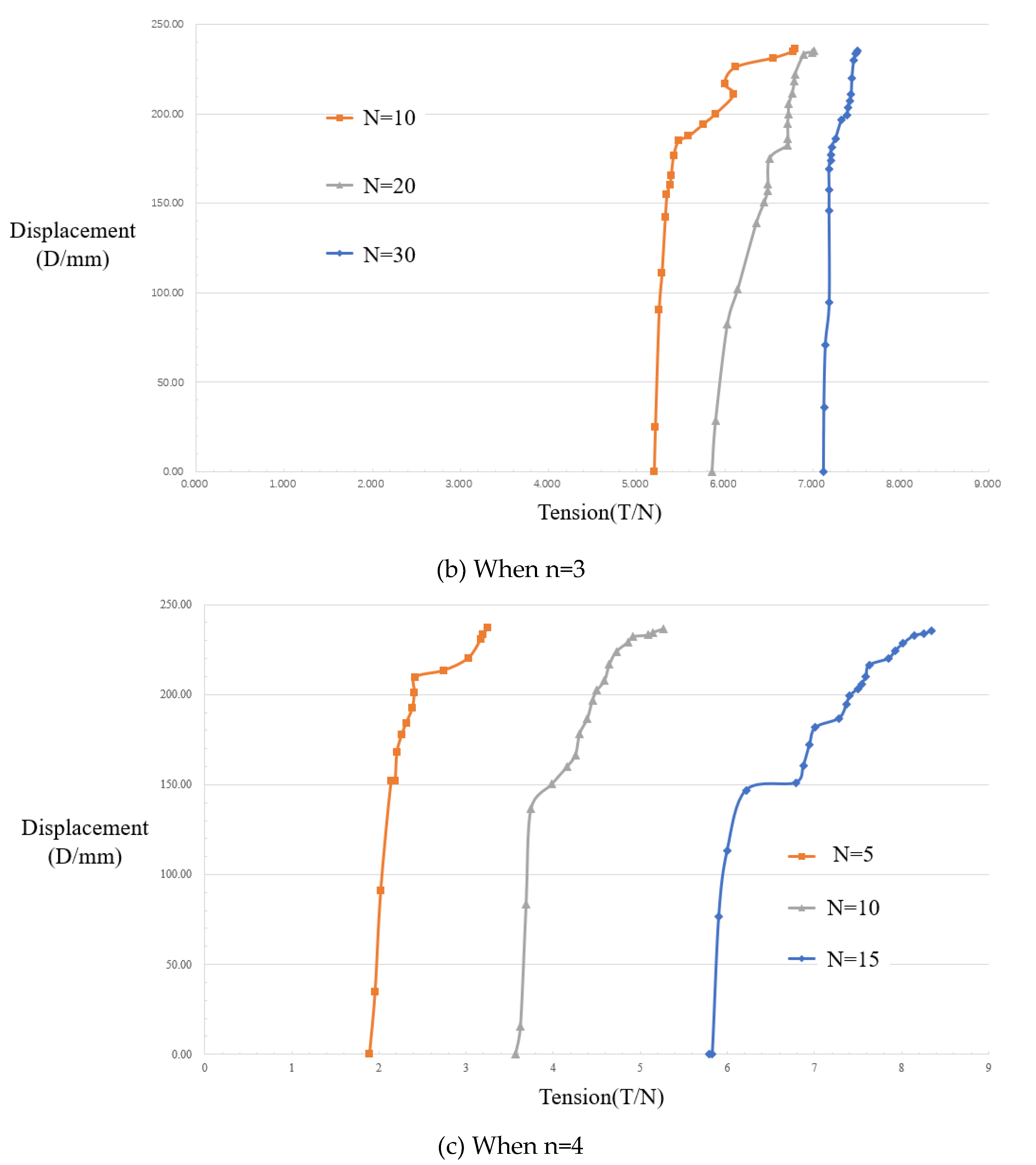
It should be noted that the point at the very end of each curve in the figure is not an artificial stop, but rather a point at which the robot fails under this load due to limitations in the load torque of the motors, for example. That is, at this point, the substrate slips significantly and the torque of the drive motors is too low to control the robot any longer, so loading measurements after the point of failure has no value. In all three graphs above, i.e., n=2, n=3 & n=4, the point of failure occurs at a displacement D of approximately 250mm, which is due to the characteristics of the robot substrate. A curve with N=0 exists in each of the plots, when the centrally located TSA rope is not twisted to provide tension T, as the original control group without variable stiffness operation. It is easy to find in the graphs that in the same set of experiments with the number of rope strands n, with the increase of the number of torsion turns N, the maximum tolerable load Fmax or the failure point is significantly shifted back, for example, in the case of n=3, the maximum load at the number of motor turns N=30 is 9.4N, which is 235% higher than the maximum load of 4N when the stiffness is unchanged, i.e., the stiffness is increased by a factor of 2.35. And between the experiments with different groups of rope strands n, the maximum load after TSA is also improving as n increases, for example, the maximum load at n=4 is 9.9N, while the maximum load at n=2 is 8.6N, which is an improvement of 115%. However, it is easy to see that the degree of torsion cannot be described by the same use of the number of motor rotations N, even when all other conditions are the same, due to the limitation of the change in the number of motor and rope strands. This is because the number of motor rotations N is only an intuitive independent variable, but what causes the change in stiffness is actually the rope tension T. Therefore, with the help of a dynamometer, the intuitive relationship between the rope tension T and the end displacement in this paper is shown in Figure 27.
As can be seen in the figure, the tension T provided by the TSA increases after the number of motor revolutions N is increased or the number of rope strands n is increased. Further, T is essentially the friction force between the substrates to resist the displacement after the external load is increased, therefore, the larger T is, also represents the better robot stiffness K. Since then, the feasibility of the TSA method has been verified to be the same as that of the continuum machine with human-locked variable stiffness, and the reasonableness of the proposed substrate in this paper. For the experimental data in Figure 27 Comparison between different numbers of strands, it can be seen that the more the number of rope strands, the better the stiffness provided. The experiment belongs to all the large changes at a displacement of about 150 mm, which is due to the structure of the matrix, there has been a part of the matrix to produce slippage, but the whole is still not failed. In particular, the tension pattern presented in the data at n=3 is significantly different from that at n=2 and n=4. This is because the rope is more compact and the torsional transfer is more homogeneous at n=3 compared to the other two cases, so the data are more intensive. The overall stiffness experiment proves that the theory of variable stiffness of the continuum robot TSA designed in this paper for the spine-like configuration is valid and the method is effective.
4. Conclusions
(1) In order to improve the stiffness of the continuum robot, this paper adopts a multi-strand rope force-locking continuum robot design based on TSA and proposes a spine-like matrix design suitable for force-locking. For the range of motion of the spine-like matrix, a mathematical model is constructed for the geometric relationship between the stiffness of the continuum robot and the TSA described in this paper.
(2) The robot experimental platform described in this paper was assembled and tested for motion feasibility, and the results showed that the robot exhibited excellent flexibility. Secondly, the retraction test was carried out to verify the formula, which provides a theoretical basis for the subsequent control of the robot. Finally, the variable stiffness performance test was carried out under different loads, rope tensioning force and number of rope strands. The data show the validity and theoretical correctness of the design of the multi-strand rope force-locked variable stiffness continuum robot, and the variable stiffness effect is significantly better than that of the variable stiffness method of a single rope without torsion, which provides a new way of thinking for the variable stiffness design of continuum robots.
(3) In future work, there are also still some problems that need to be improved: from the retraction results, it can be seen that a large amount of additional experimental data is still needed to better eliminate control errors; from the results of the stiffness experiments, it can be seen that the displacement-axial force-load and other factors do not follow a strictly linear relationship, and future work should explore the impact of factors such as rope tension when applying TSA to continuum robots; the motor torque in this study also limits data collection; in future work, a higher-torque motor can be adopted to acquire more experimental data.
Author Contributions
Conceptualisation, CHEN.,YUTONG.; methodology, CHEN.YUTONG; validation, YUTONG,ZHIXING.SHIYING; supervision CHEN,ZHENG, LI,LUO, writing—original draft preparation, YUTONG. All authors have read and agreed to the published version of the manuscript.
Data Availability Statement
The data used to support the findings of this study are included in the paper.
Acknowledgments
This work supported by the Project (2024C04052) Zhejiang Province’s “Vanguard Leading Geese+X” R&D Key Project; Project(2023-JC-YB-313) supported by the Natural Science Basic Research Plan-General Project of Shaanxi Province; Project(2023-JC-YB-294) supported by the Natural Science Basic Research Plan-General Project of Shaanxi Province; Project(2022KXJ032) Shaanxi Province Qin Chuangyuan “ Scientists + Engineers” Team Construction; Project (52002309) supported by the National Natural Science Foundation of China.
Conflicts of Interest
The authors declare that they have no conflicts of interest.
References
- Webster, R. J. Design and Kinematic Modeling of Constant Curvature Continuum Robots: A Review. The International Journal of Robotics Research 2010, vol. 29, 1661–1683. [Google Scholar] [CrossRef]
- K. Tao et al., “Deep-Learning Enabled Active Biomimetic Multifunctional Hydrogel Electronic Skin,”. ACS Nano 2023, vol. 17(no. 16), 16160–16173. [CrossRef] [PubMed]
- Kai, T.; Lihua, T.; Jin, W.; Woh, L. S.; Honglong, C.; Jianmin, M. Investigation of Multimodal Electret-Based MEMS Energy Harvester With Impact-Induced Nonlinearity. Journal of Microelectromechanical Systems 2018, vol. 27(no. 2), 276–288. [Google Scholar]
- Oliver-Butler, K.; Till, J.; Rucker, D. C. Continuum Robot Stiffness Under External Loads and Prescribed Tendon Displacements. IEEE Trans. Robotics 2019, vol. 35, 403–419. [Google Scholar] [CrossRef]
- G. Qin et al., “Design and development of a cable-driven elephant trunk robot with variable cross-sections,”. The Industrial Robot 2023, vol. 50, 520–529. [CrossRef]
- Huang, C. Research on Trajectory Planning and Motion Control of Multi Joint Serpentine Robot. Master’s Thesis, University of Electronic Science and technology, 2021. [Google Scholar]
- C. G, P. M.T, and R. T, “Sensor-based guidance control of a continuum robot for a semi-autonomous colonoscopy,”. Robotics and Autonomous Systems 2008, vol. 57, 712–722.
- Q. Pan and J. Luo et al., “Configuration design and optimization of incision type single port laparoscopic continuum surgical robot,”. Journal of Mechanical Engineering 2023, vol. 59, 55–67. [CrossRef]
- G. Sun and X. Zhang et al., “Research on Measurement Error of Multi core Fiber Three dimensional Shape and Position for Precise Operation of Continuum Robots,”. Journal of Mechanical Engineering 2024, vol. 60, 68–82. [CrossRef]
- Bin, Z.; Lingyun, Z.; Zhonghao, W.; Kai, X. A continuum manipulator for continuously variable stiffness and its stiffness control formulation. Mechanism and Machine Theory 2019, vol. 149. [Google Scholar]
- Robotics; New Robotics Data Have Been Reported by Researchers at University of California (Controllable and reversible tuning of material rigidity for robot applications). Journal of Robotics & Machine Learning 2018, 139.
- Wang, P.; Guo, S.; Wang, X.; Wu, Y. Design and Analysis of a Novel Variable Stiffness Continuum Robot With Built-in Winding-Styled Ropes. IEEE Robotics and Automation Letters 2022, vol. 7(no. 3), 6375–6382. [Google Scholar] [CrossRef]
- Huan, A. S.; Xu, W.; Ren, H. Investigation of a stiffness varying mechanism for flexible robotic system. 2016 IEEE International Conference on Mechatronics and Automation, 2016; pp. 828–833. [Google Scholar] [CrossRef]
- Cao, Y. Research on Continuous Robot for Minimally Invasive Interventional Surgery with Variable Stiffness. Master’s Thesis, Nanjing University of Aeronautics and Astronautics, 2019. [Google Scholar]
- S. Jiang et al., “A variable-stiffness continuum manipulators by an SMA-based sheath in minimally invasive surgery,”. The International Journal of Medical Robotics and Computer Assisted Surgery 2020, vol. 16(no. 2), e2081. [CrossRef]
- Nalini, D.; Ruth, D. J. S.; Dhanalakshmi, K. Design of a variable stiffness actuator using shape memory alloy wire. 2016 IEEE 7th Power India International Conference (PIICON), 2016; pp. 1–5. [Google Scholar] [CrossRef]
- C. Yang et al., “Geometric constraint-based modeling and analysis of a novel continuum robot with Shape Memory Alloy initiated variable stiffness,”. The International Journal of Robotics Research 2020, vol. 39(no. 14), 1620–1634. [CrossRef]
- T. Liao, Z. T. Ho Tse, and H. Ren, “Variable Stiffness Actuators Embedded with Soft-bodied Polycaprolactone and Shape Memory Alloy Wires,” in 2019 IEEE/ASME International Conference on Advanced Intelligent Mechatronics (AIM), Hong Kong, China: IEEE, Jul. 2019, pp. 108–113. [CrossRef]
- Spaggiari, A. Properties and applications of Magnetorheological fluids. Frattura ed Integrità Strutturale 2012, vol. 7(no. 23), 48–61. [Google Scholar] [CrossRef]
- Y. Li, T. Ren, Y. Chen, and M. Z. Q. Chen, “A Variable Stiffness Soft Continuum Robot Based on Pre-charged Air, Particle Jamming, and Origami,” in 2020 IEEE International Conference on Robotics and Automation (ICRA), Paris, France: IEEE, May 2020, pp. 5869–5875. [CrossRef]
- D. C. F. Li, Z. Wang, B. Ouyang, and Y.-H. Liu, “A Reconfigurable Variable Stiffness Manipulator by a Sliding Layer Mechanism,” in 2019 International Conference on Robotics and Automation (ICRA), Montreal, QC, Canada: IEEE, May 2019, pp. 3976–3982. [CrossRef]
- Kanada, A.; Mashimo, T. Switching Between Continuum and Discrete States in a Continuum Robot With Dislocatable Joints. IEEE Access 2021, vol. 9, 34859–34867. [Google Scholar] [CrossRef]
- Zuo, S.; Iijima, K.; Tokumiya, T.; Masamune, K. Variable stiffness outer sheath with ‘Dragon skin’ structure and negative pneumatic shape-locking mechanism. Int J CARS 2014, vol. 9(no. 5), 857–865. [Google Scholar] [CrossRef]
- Degani, A.; Choset, H.; Wolf, A.; Zenati, M. A. “Highly Articulated Robotic Probe for Minimally Invasive Surgery”.
- Y. Chen, J. H. Chang, A. S. Greenlee, K. C. Cheung, A. H. Slocum, and R. Gupta, “Multi-turn, tension-stiffening catheter navigation system,” in 2010 IEEE International Conference on Robotics and Automation, 2010, pp. 5570–5575. [CrossRef]
- D. Popov, I. Gaponov, and J.-H. Ryu, “Towards variable stiffness control of antagonistic twisted string actuators,” in 2014 IEEE/RSJ International Conference on Intelligent Robots and Systems, 2014, pp. 2789–2794. [CrossRef]
- Chen, G.; Wu, Y.; Zheng, J.; Shi, H.; Li, F.; Qin, C. Research on the method of force-locking and variable stiffness for continuum robot with the spinal-like configuration. Journal of the Brazilian Society of Mechanical Sciences and Engineering 2024, vol. 46(no. 10), 627. [Google Scholar] [CrossRef]
- D. Popov, I. Gaponov, and J.-H. Ryu, “A study on twisted string actuation systems: Mathematical model and its experimental evaluation,” in 2012 IEEE/RSJ International Conference on Intelligent Robots and Systems, Vilamoura-Algarve, Portugal: IEEE, Oct. 2012, pp. 1245–1250. [CrossRef]
- M. Suzuki, T. Mayahara, and A. Ishizaka, “Redundant muscle coordination of a multi-DOF robot joint by online optimization,” in 2007 IEEE/ASME international conference on advanced intelligent mechatronics, 2007, pp. 1–6. [CrossRef]
- Bilancia, P.; Berselli, G. Conceptual design and virtual prototyping of a wearable upper limb exoskeleton for assisted operations. Int J Interact Des Manuf 2021, vol. 15(no. 4), 525–539. [Google Scholar] [CrossRef]
- Baek, S.; Ryu, J.-H. Tension Control of Twisted String Actuators in Variation of Stiffness and Original Length of Strings. IEEE/ASME Trans. Mechatron. 2023, vol. 28(no. 5), 2483–2494. [Google Scholar] [CrossRef]
- X. Zhu and H. Hu, “A Controllable Stiffness Robotics for Natural Orifice Transluminal Endoscopic Surgery,” in 2021 4th World Conference on Mechanical Engineering and Intelligent Manufacturing (WCMEIM), Shanghai, China: IEEE, Nov. 2021, pp. 45–48. [CrossRef]
- Kim, Y.-J.; Cheng, S.; Kim, S.; Iagnemma, K. A Stiffness-Adjustable Hyperredundant Manipulator Using a Variable Neutral-Line Mechanism for Minimally Invasive Surgery. IEEE Trans. Robot. 2014, vol. 30(no. 2), 382–395. [Google Scholar] [CrossRef]
- Kong, L.; Wang, L. Strength Failure Analysis of Vectran Fiber Tethered Cable. Synthetic fiber industry 2023, vol. 46, 84–88. [Google Scholar]
- T. Tsabedze, E. Hartman, C. Brennan, and J. Zhang, “A Compliant Robotic Wrist Orthosis Driven by Twisted String Actuators,” in 2021 International Symposium on Medical Robotics (ISMR), Atlanta, GA, USA: IEEE, Nov. 2021, pp. 1–7. [CrossRef]
Figure 1.
Spina-like continuum configuration.
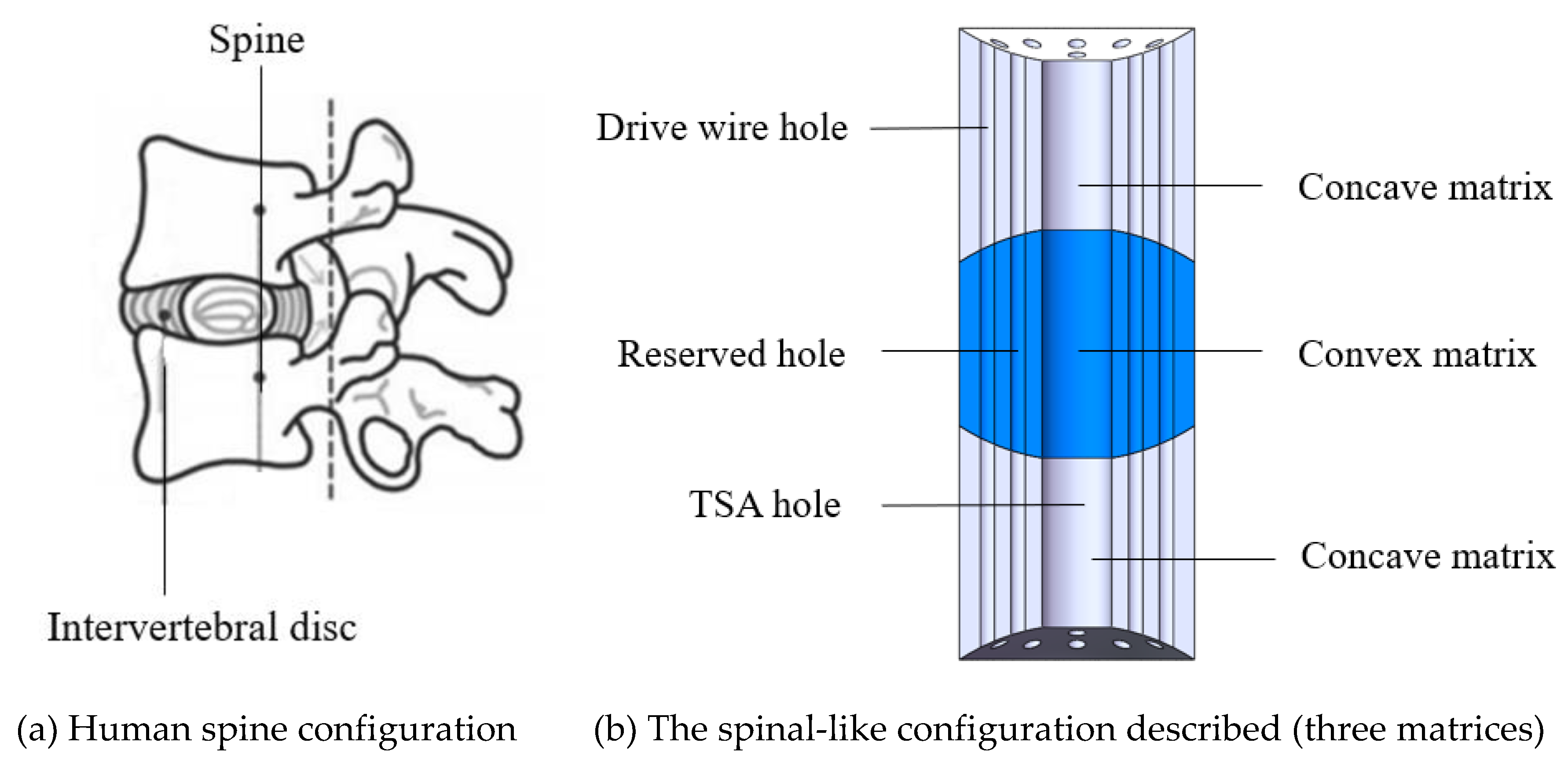
Figure 2.
Two kinds of matrix configurations.
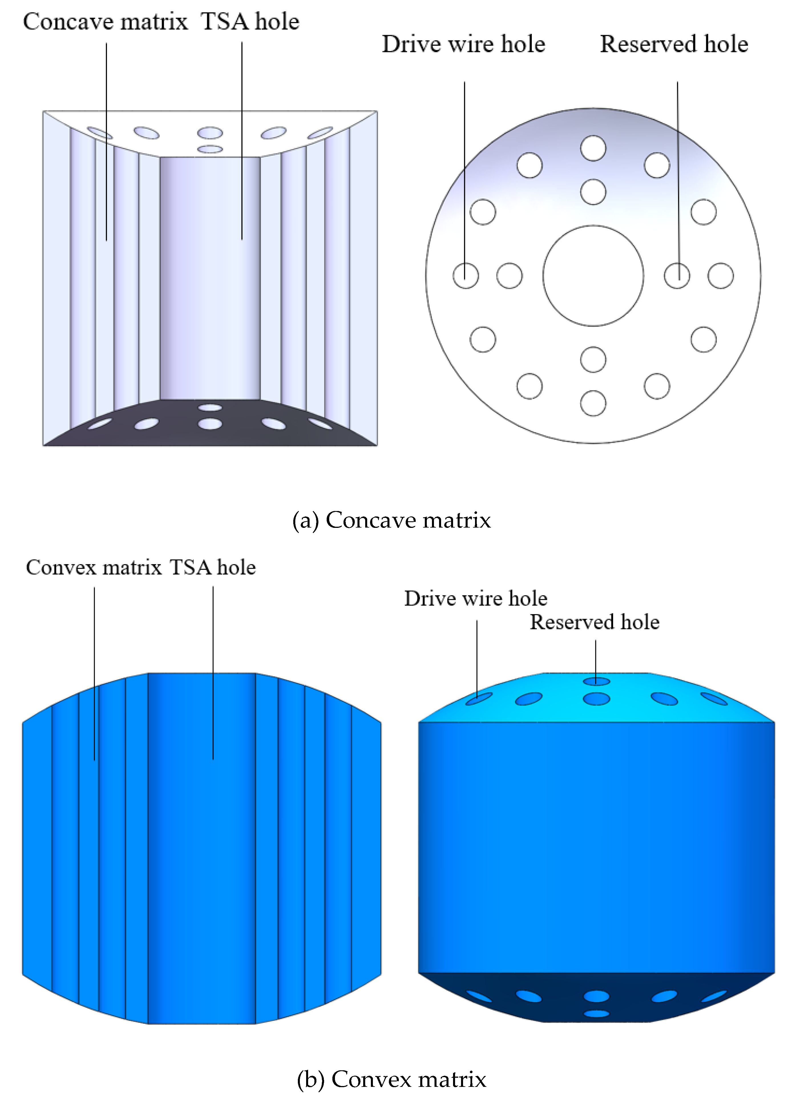
Figure 4.
Image of continuum joint.
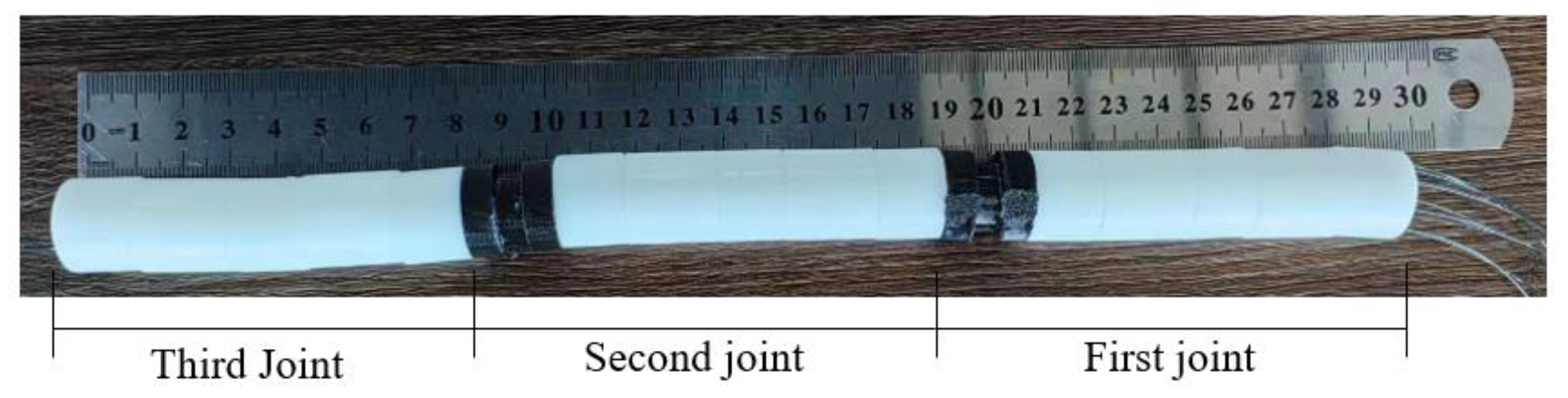
Figure 5.
Model diagram of the rollback mechanism.
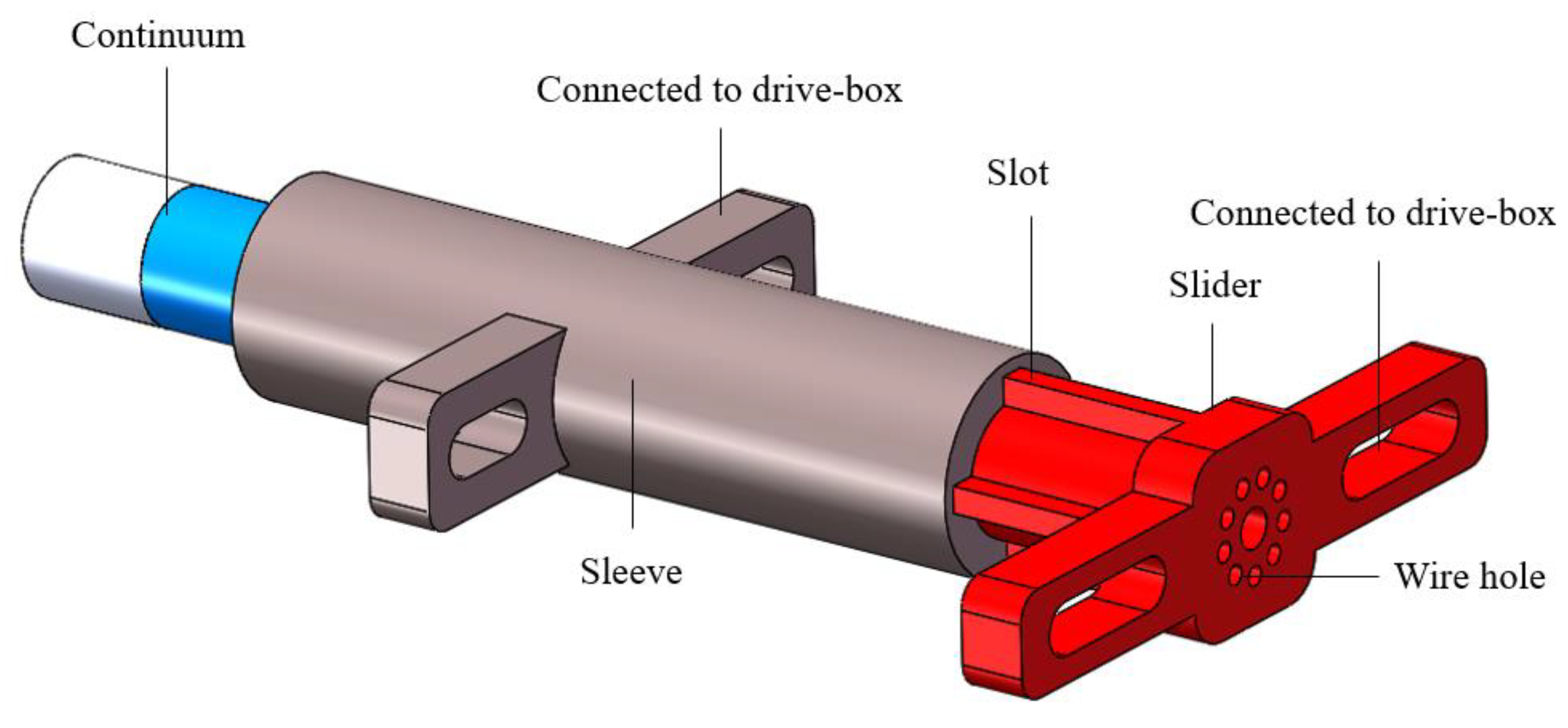
Figure 6.
Motion principle of the rollback mechanism.
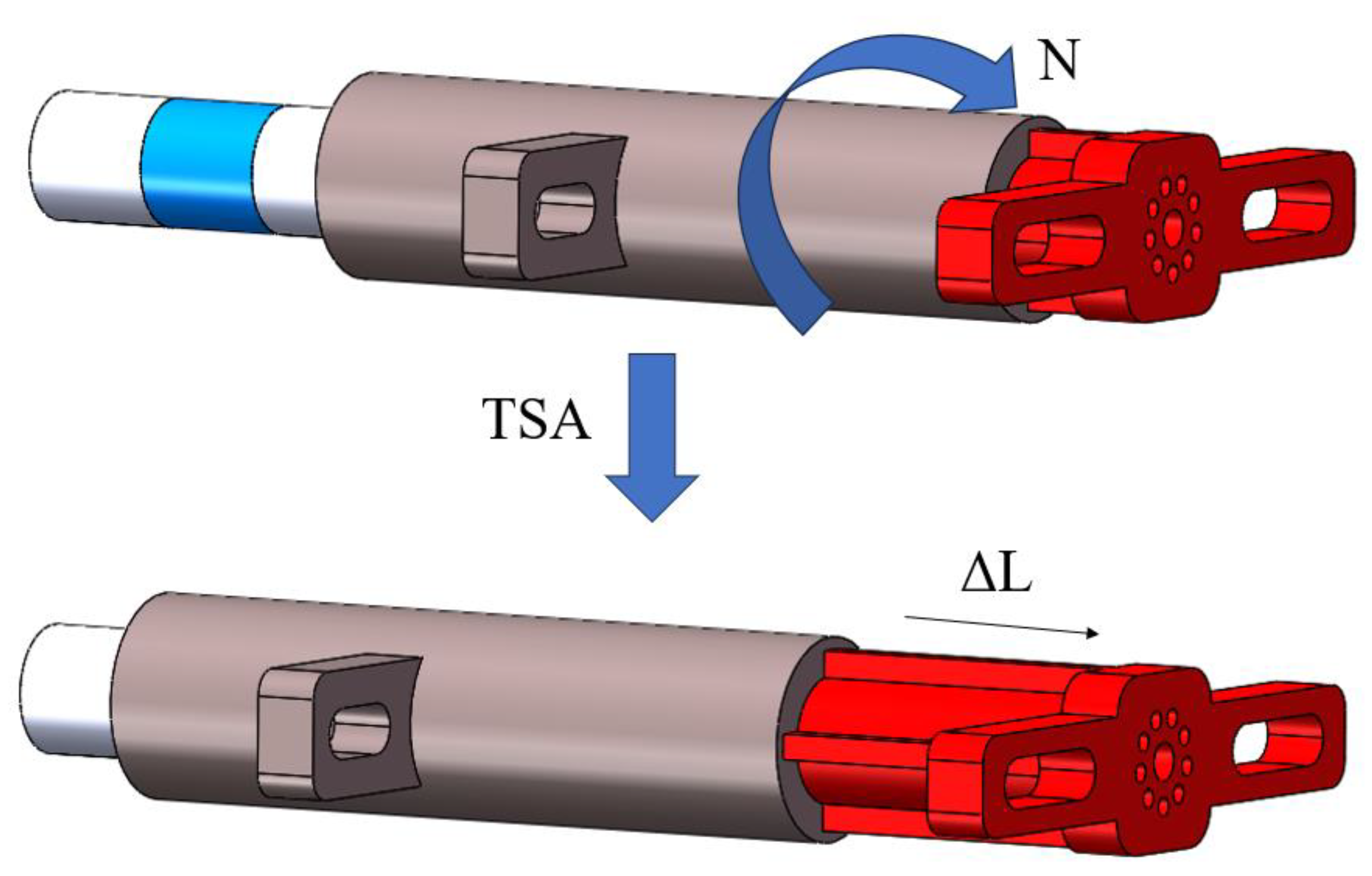
Figure 7.
Geometric model of string twisting.
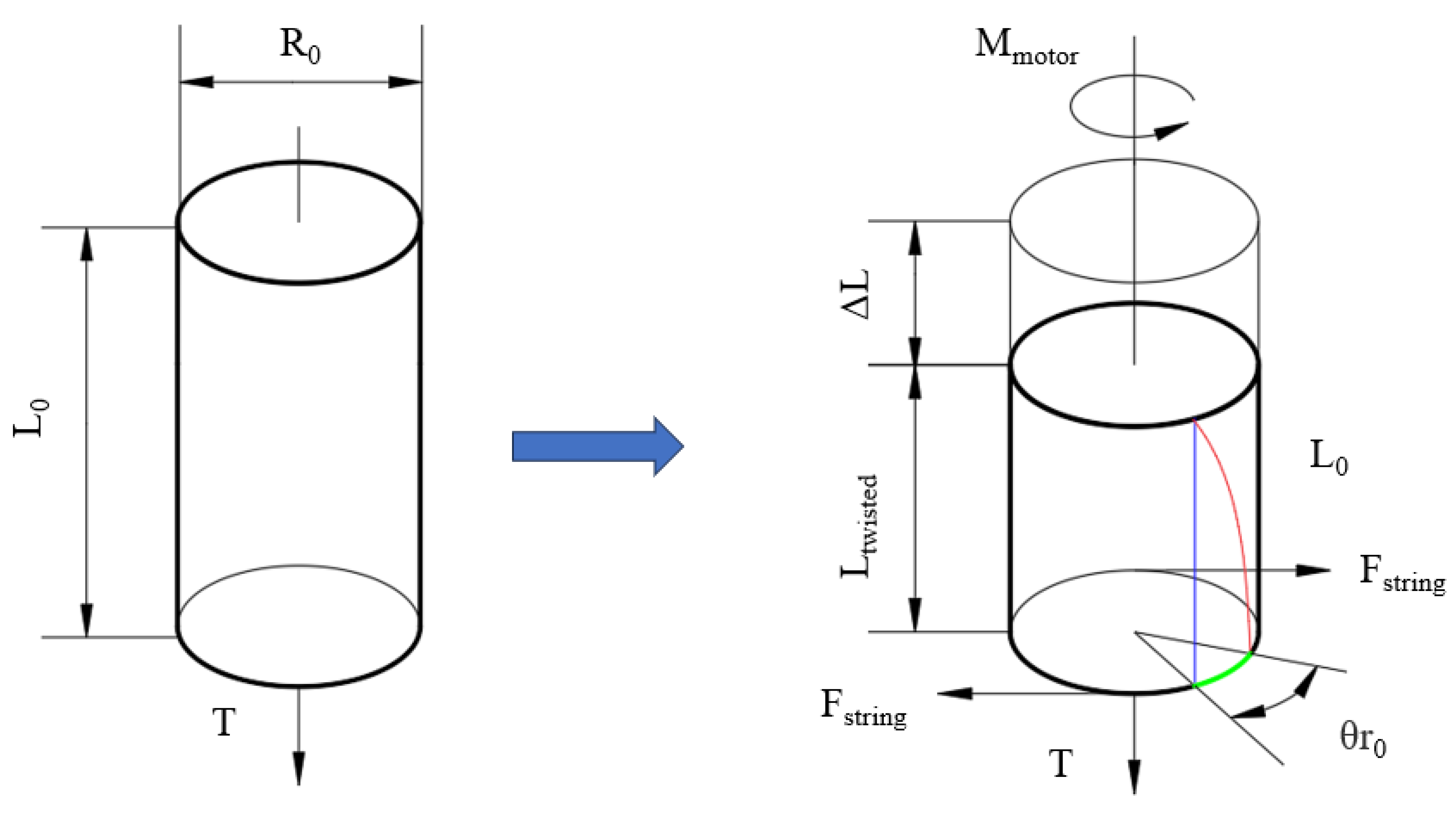
Figure 8.
Cylinder unfolding model.
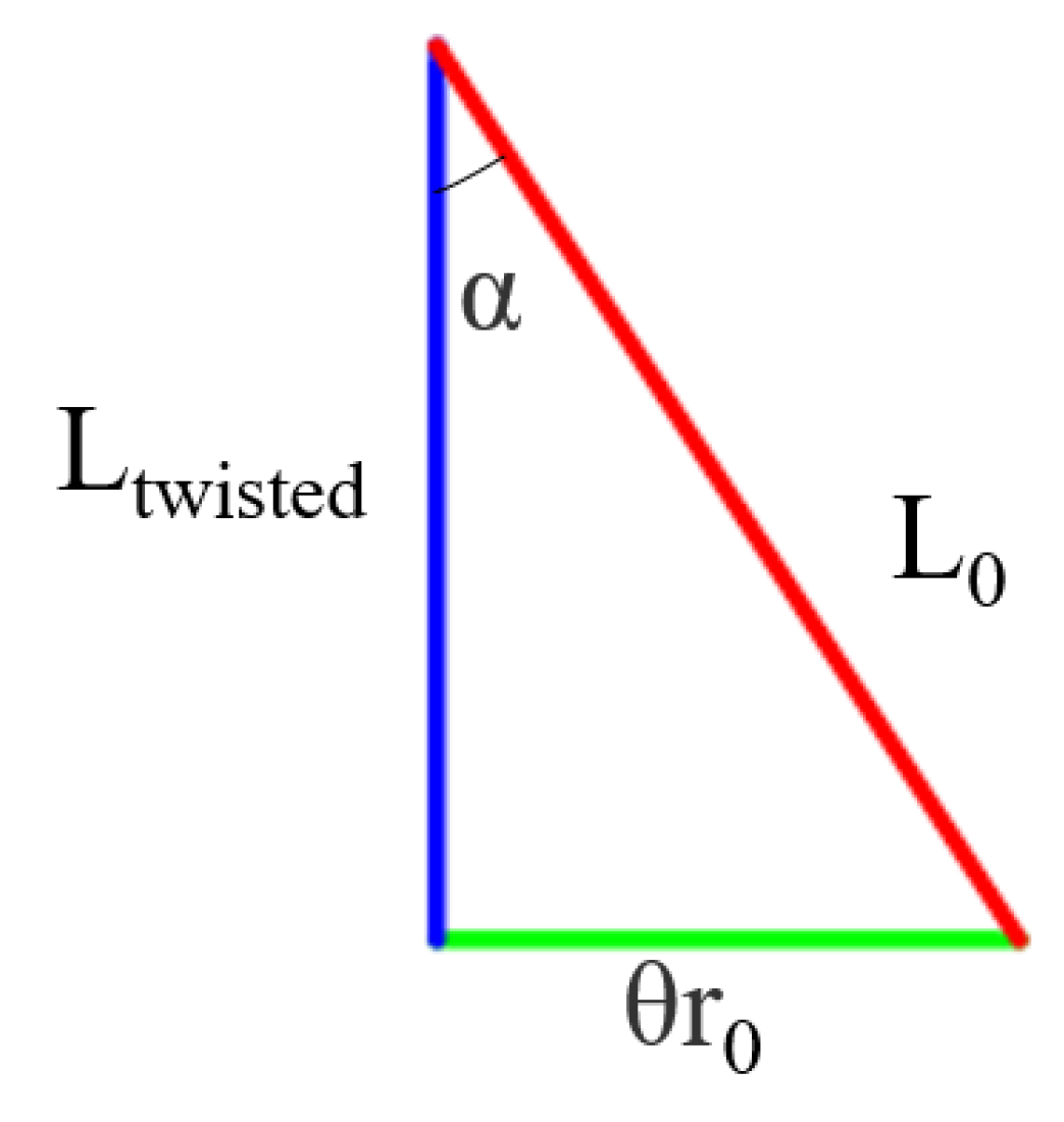
Figure 9.
Changes in radius during twisting of multi-string.
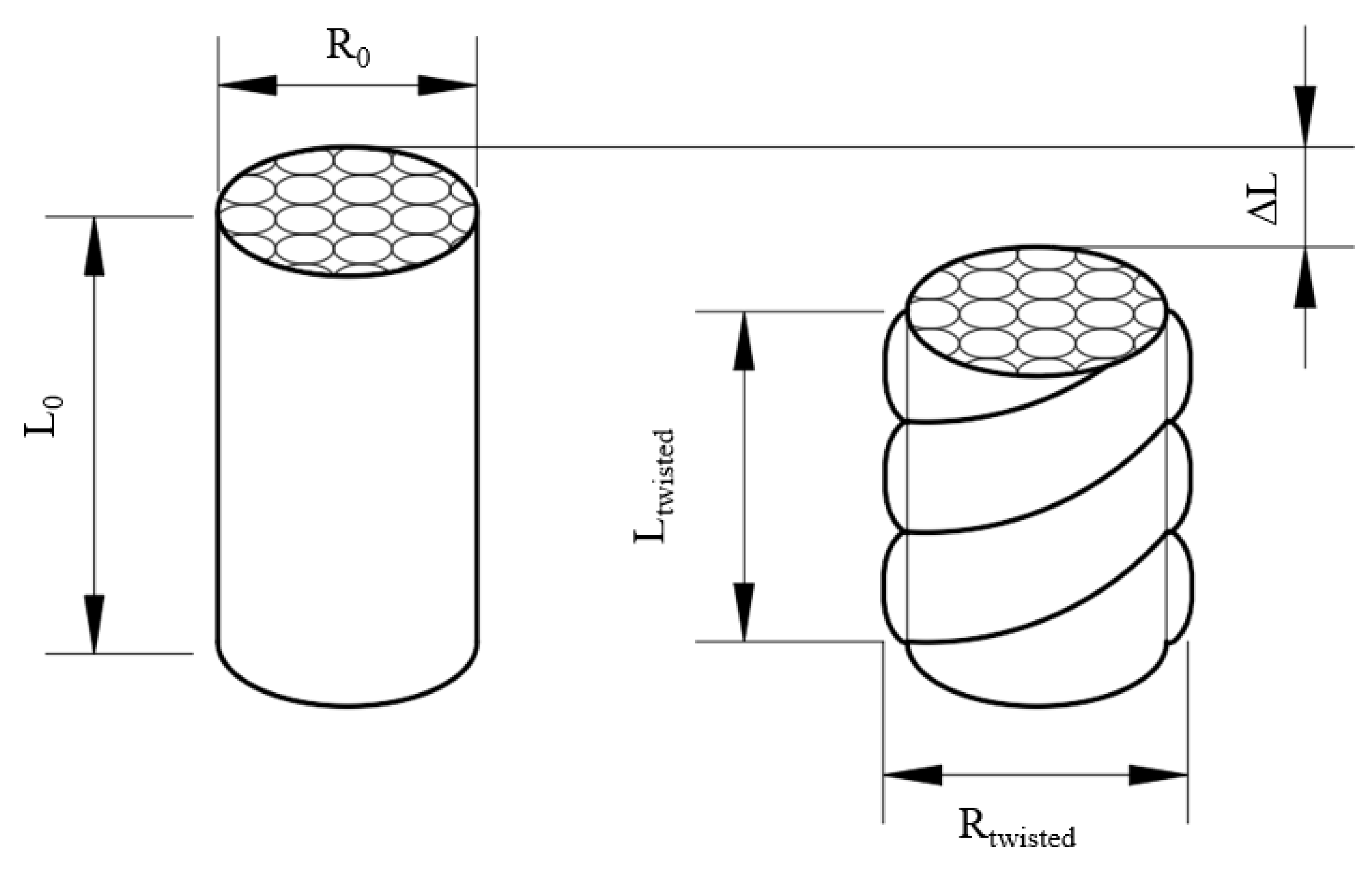
Figure 10.
Cross section under multiple-string.
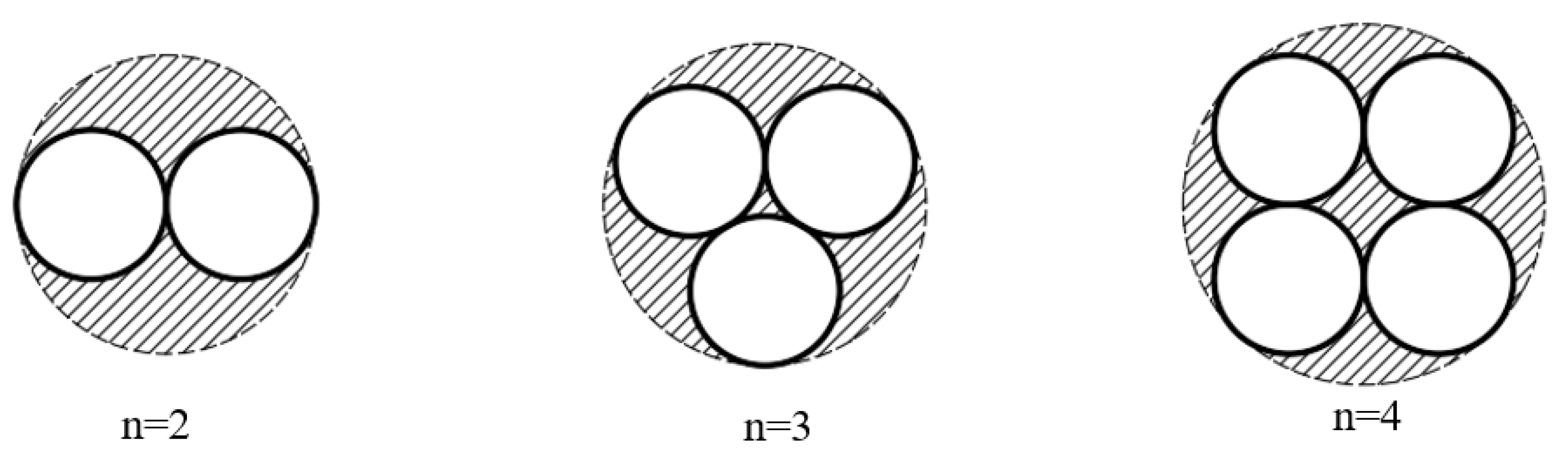
Figure 11.
Schematic diagram of variable stiffness for continuous force-locking.
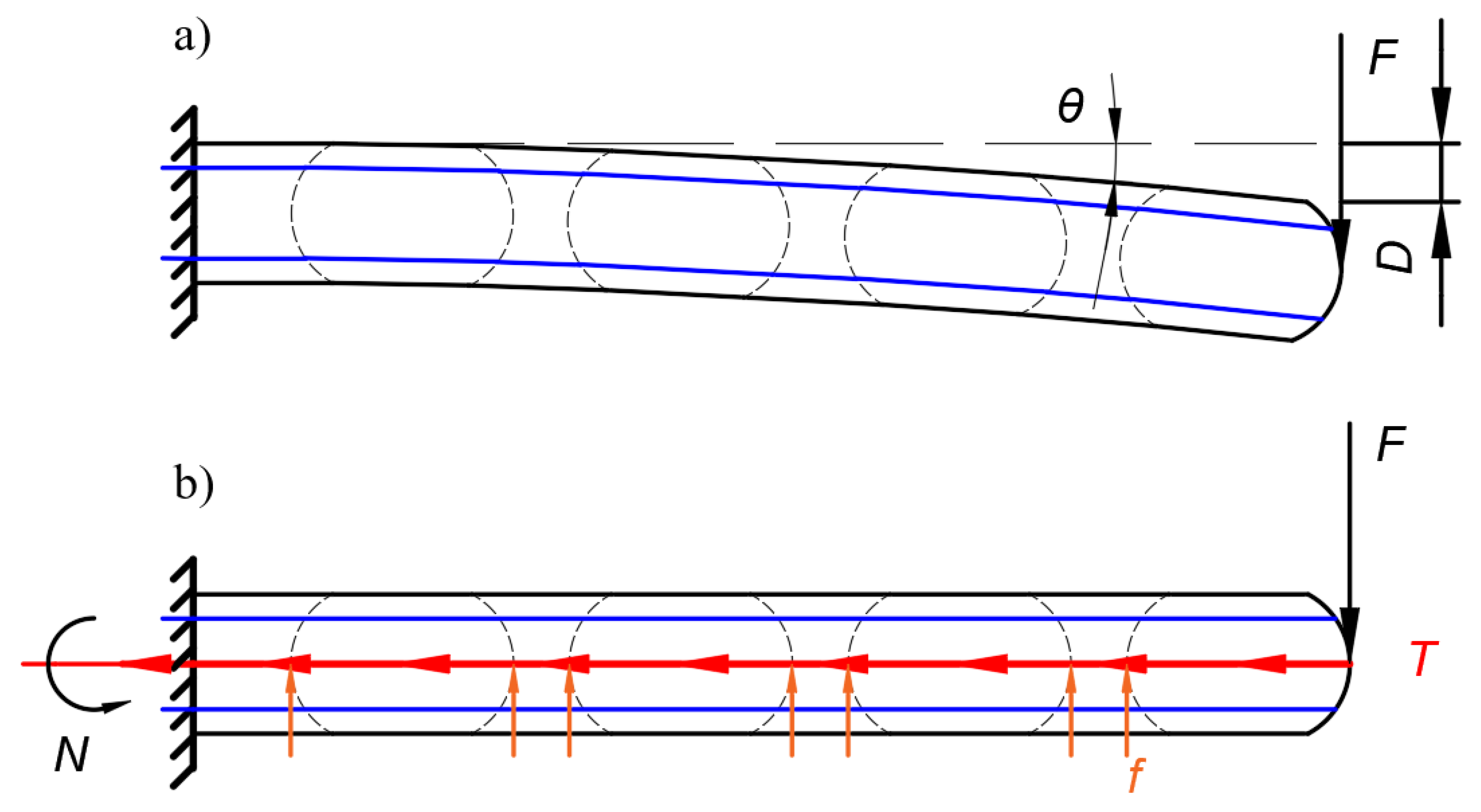
Figure 12.
Cantilever beam model of robot.
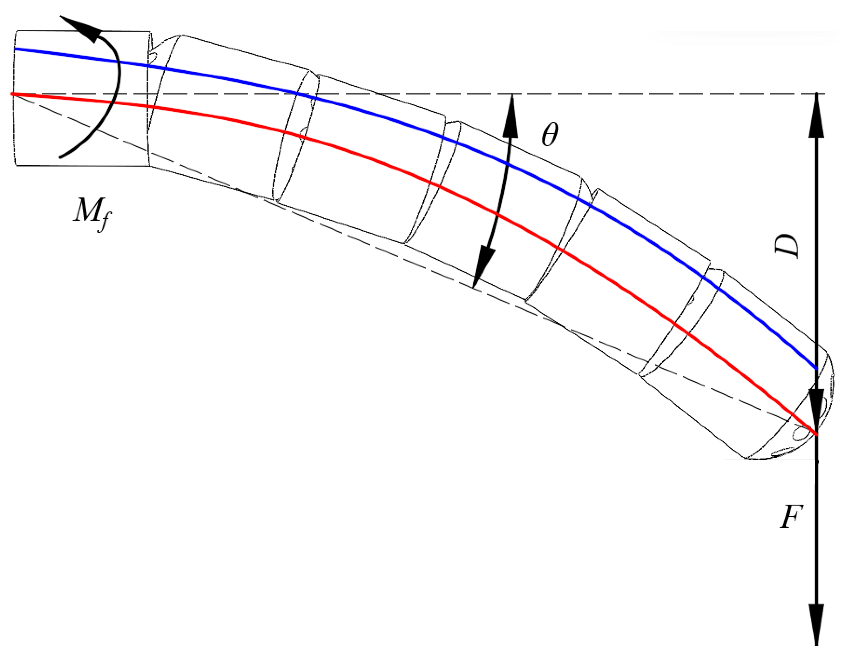
Figure 13.
Schematic diagram of matrix cross-section.
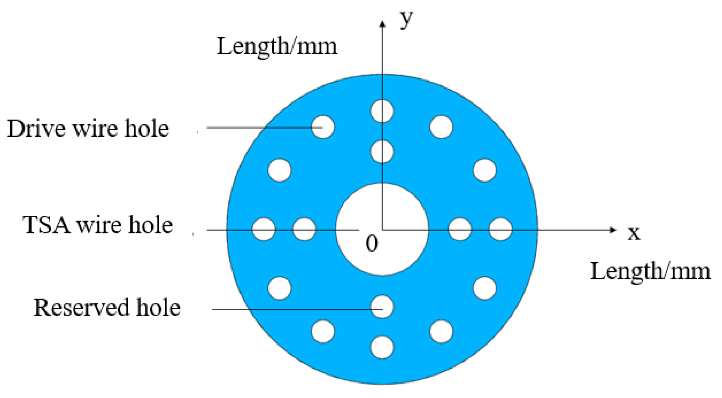
Figure 14.
Schematic diagram of matrix stress balance when T=0.
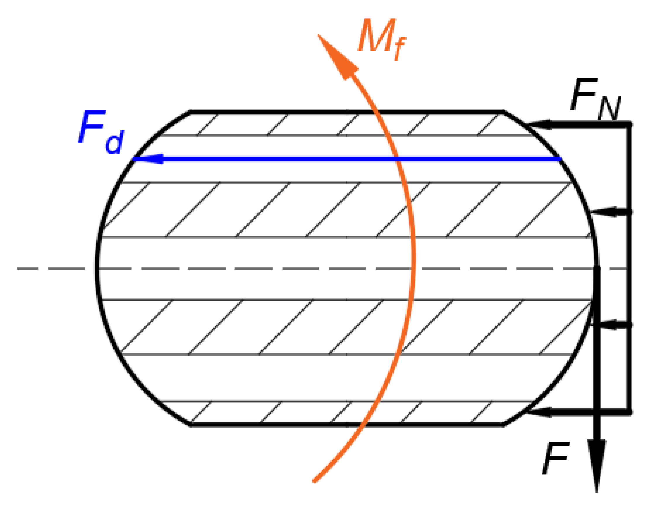
Figure 15.
Schematic diagram of matrix stress when T ≠ 0.
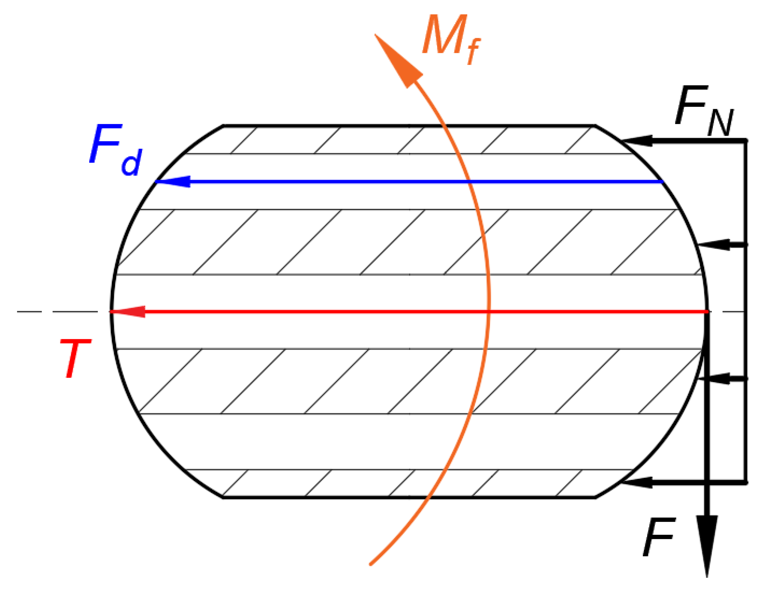
Figure 16.
No slip occurred in the matrix.
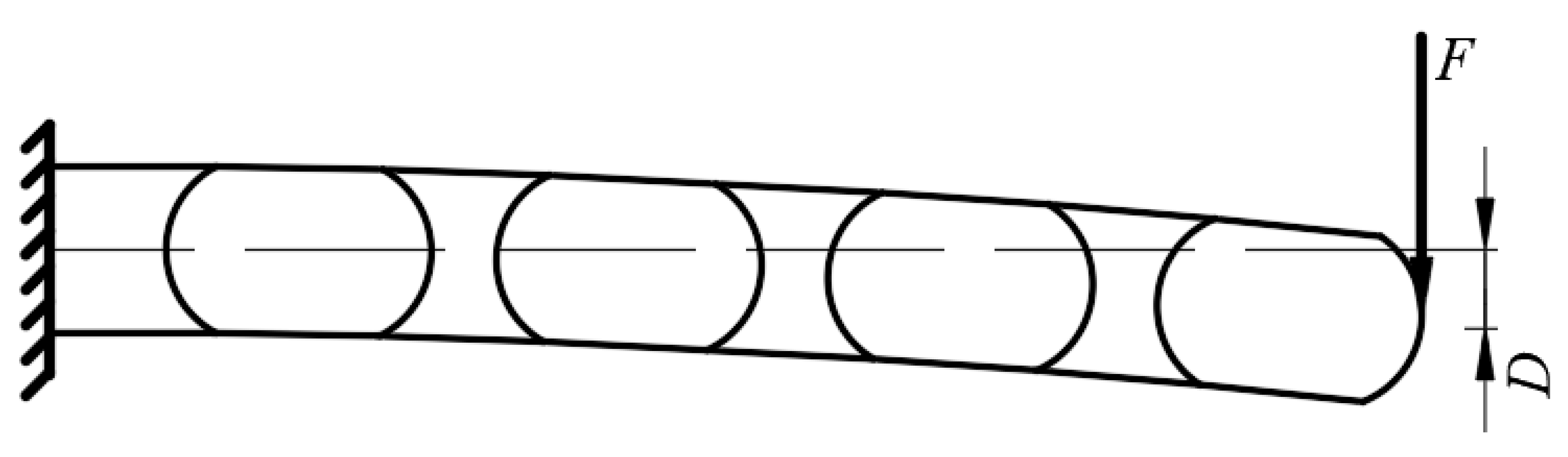
Figure 17.
Partial matrix slip occurs.
Figure 18.
Schematic diagram of robot turning angle.
Figure 19.
Physical assembly diagram of robot.
Figure 20.
Picture of TSA control part.
Figure 21.
Picture of the drive motor part.
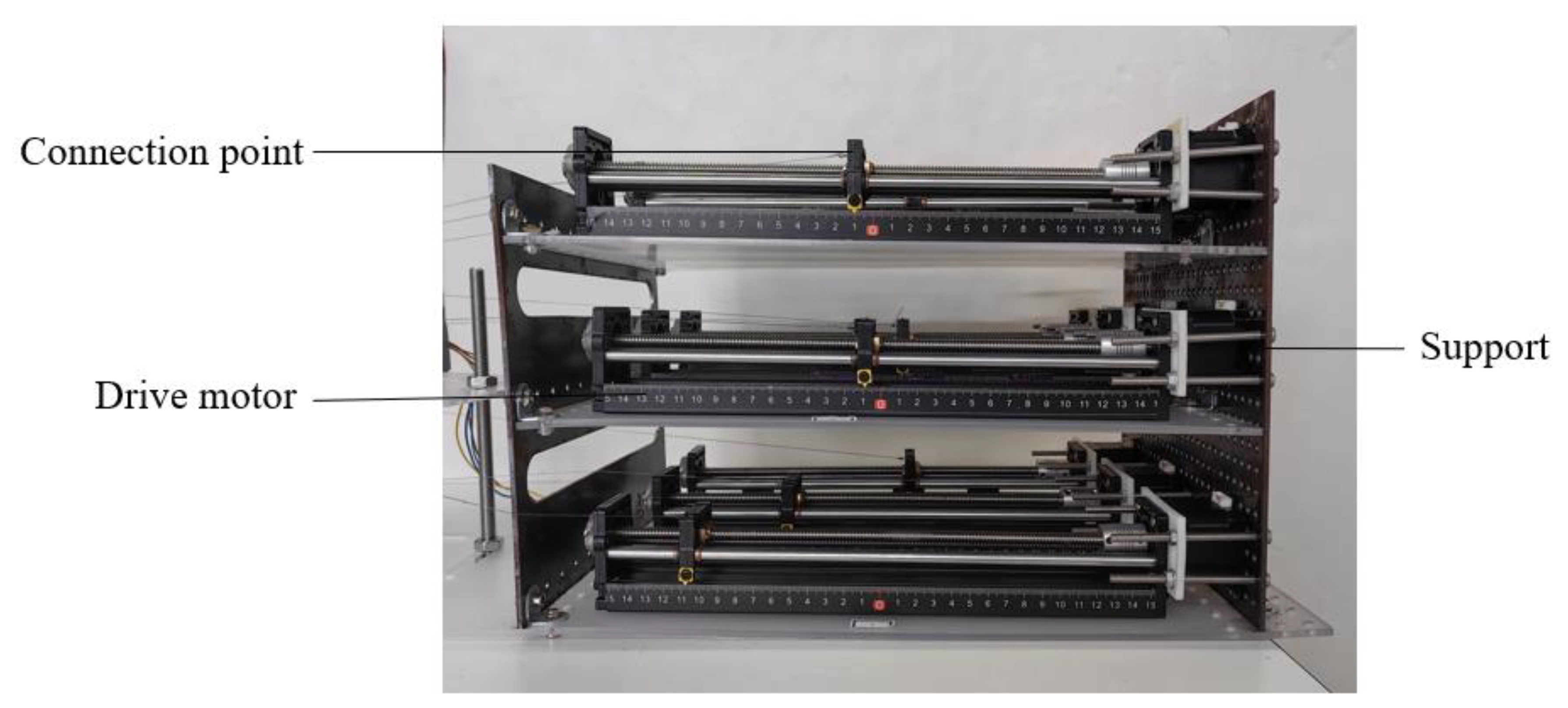
Figure 22.
Image of motion control continuum motion state.
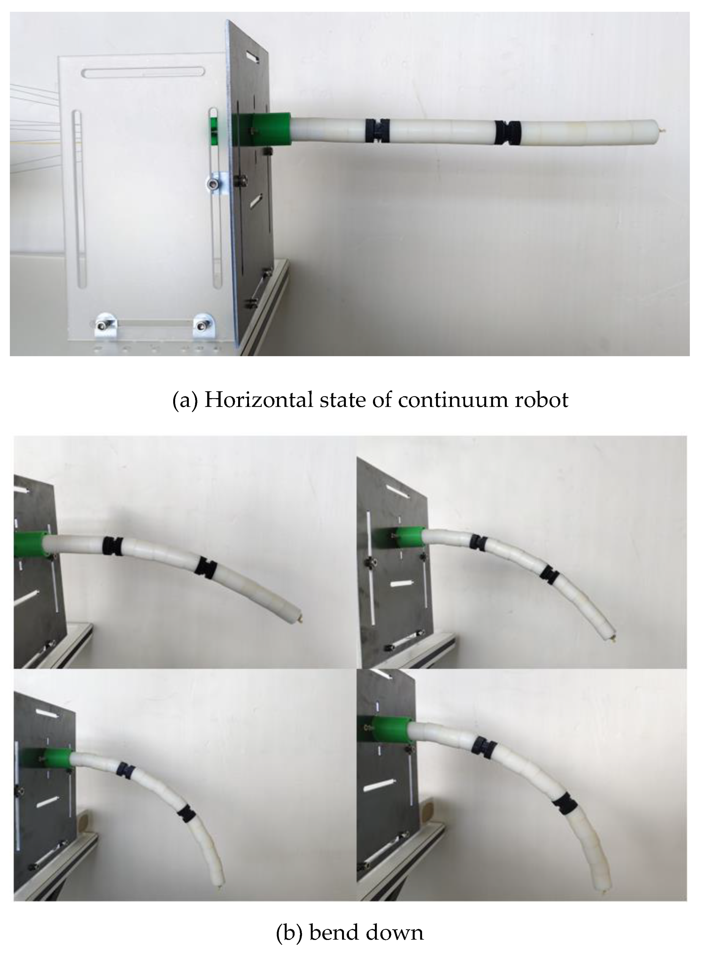
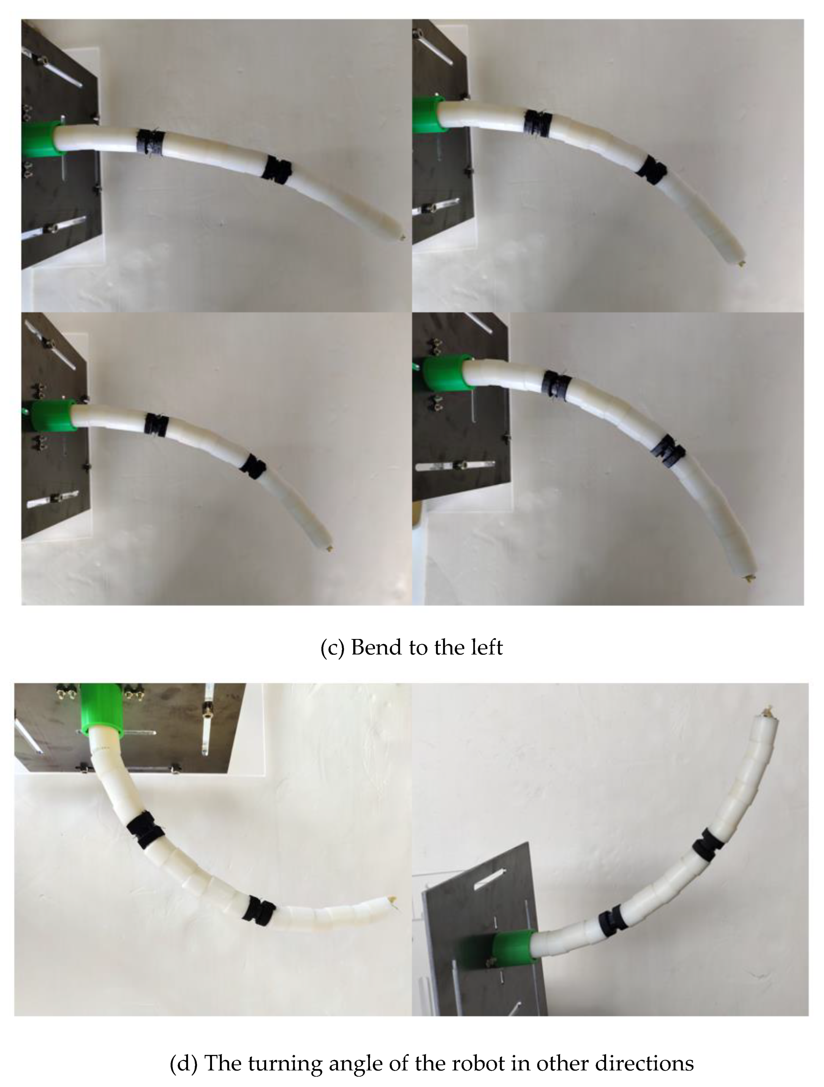
Figure 23.
The relationship between n and ΔL.
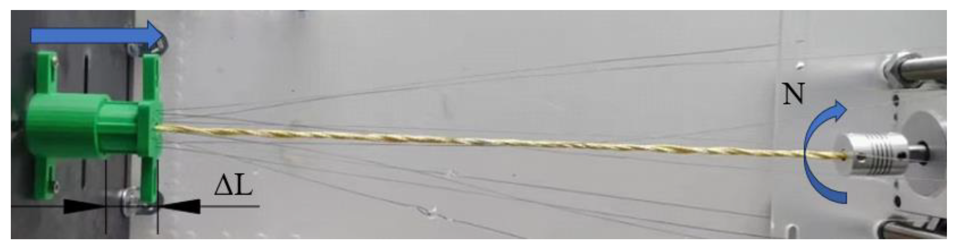
Figure 24.
Relationship diagram between ΔL and N.
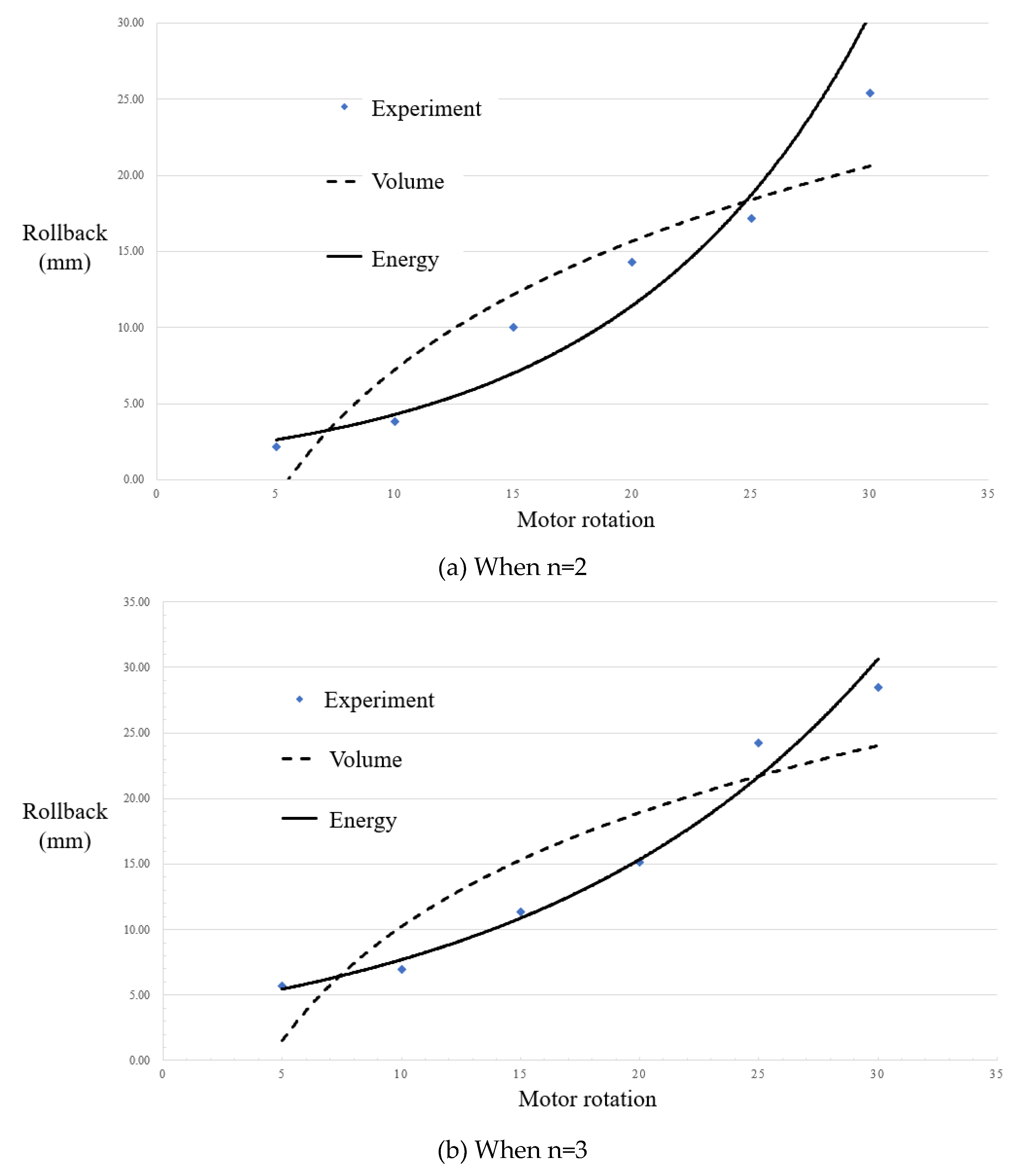
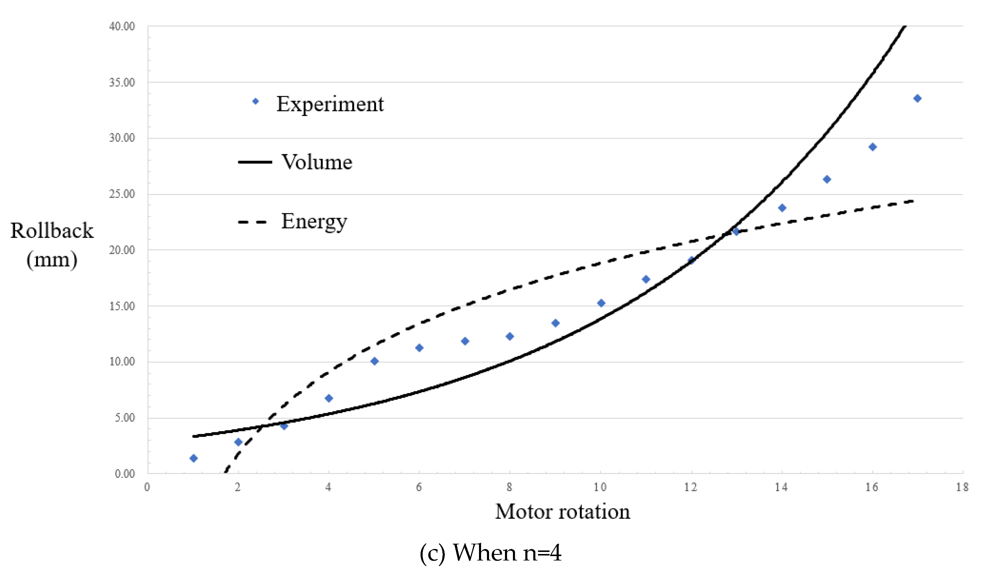
Figure 25.
Experimental diagram of displacement-angle-load.
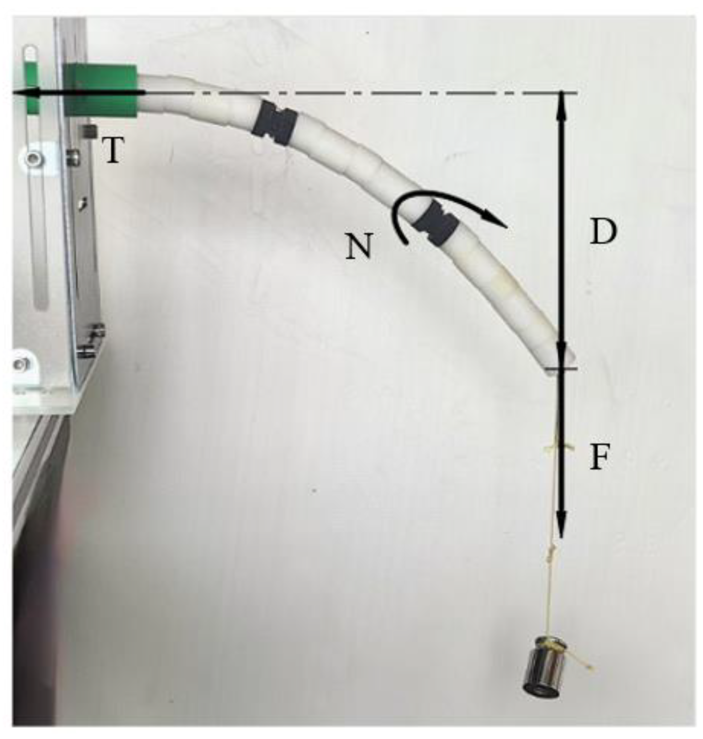
Figure 26.
Experimental results of displacement displacement-angle-load.
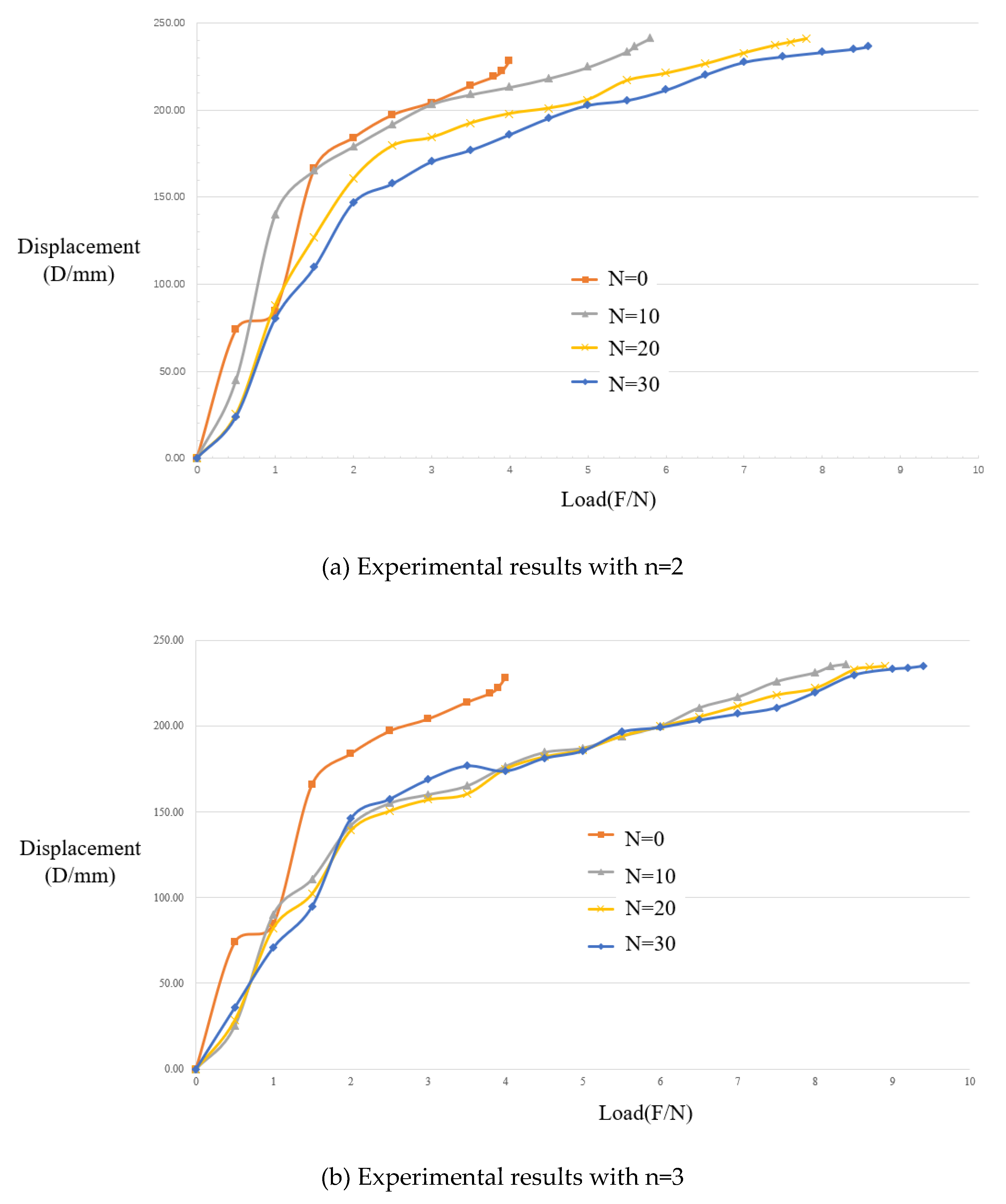
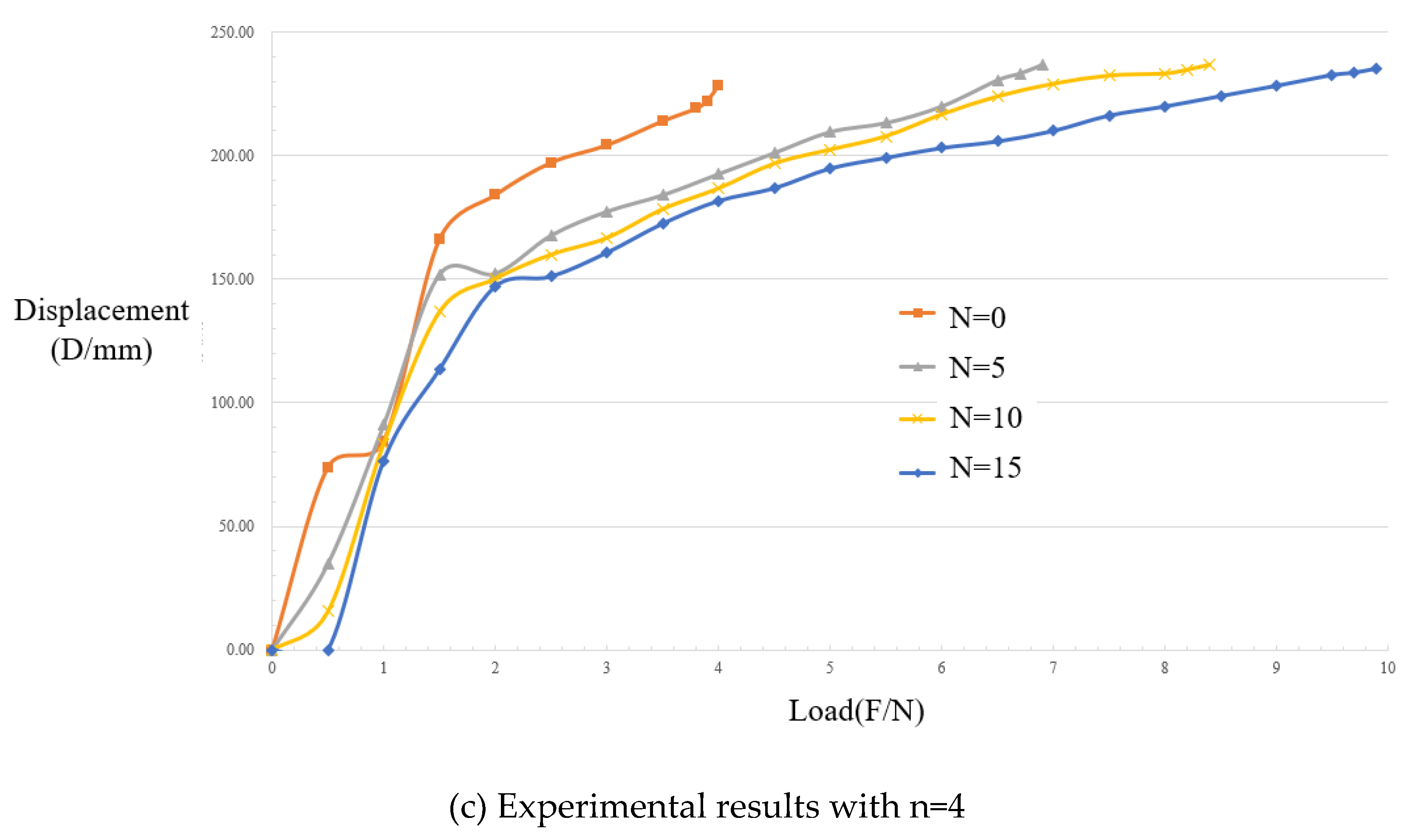
Figure 27.
Tension displacement relationship diagram.
Disclaimer/Publisher’s Note: The statements, opinions and data contained in all publications are solely those of the individual author(s) and contributor(s) and not of MDPI and/or the editor(s). MDPI and/or the editor(s) disclaim responsibility for any injury to people or property resulting from any ideas, methods, instructions or products referred to in the content. |
© 2025 by the authors. Licensee MDPI, Basel, Switzerland. This article is an open access article distributed under the terms and conditions of the Creative Commons Attribution (CC BY) license (http://creativecommons.org/licenses/by/4.0/).
Copyright: This open access article is published under a Creative Commons CC BY 4.0 license, which permit the free download, distribution, and reuse, provided that the author and preprint are cited in any reuse.


