
Submitted:
19 January 2024
Posted:
22 January 2024
You are already at the latest version
Abstract
As the most important component of soft robot, the pneumatic actuator can drive robot movement. However, the effect of the actuator pneumatic network geometry on the actuator load capacity is insufficient. In this paper, the finite element analysis method is applied to calculate the load force and stability torque of the pneumatic actuator under a wide range of length and height dimensions of the pneumatic network. The effect of the network size on the structure rigidity, load capacity and deformation of the actuator is analyzed. Based on the calculation results, the effect of network structure size on the deformation and load capacity is analyzed, and the optimal geometric results with the maximum load capacity are obtained. This study provides theoretical guidance for the structural design and optimization of the pneumatic actuator.
Keywords:
pneumatic actuator
; pneumatic network
; load capacity
Introduction
Soft robot [1,2] is a new kind of soft robot designed based on natural creatures, such as fish [3], starfish [4] and octopus [5]. Compared with traditional rigid grippers, soft robot based on bionics has gradually attracted attention due to its unique safety and adaptability. Due to the highly nonlinear characteristics of its super elastic materials, soft robots are capable of adapting to various unstructured environments and offer improved safety with humans. They have been widely applied in different fields such as healthcare, services and intelligence.
The software actuator can drive the robot's movement and is the core component , [6,7] of the robot. At present, the common driving methods include intelligent material actuator [8], chemical actuator [9], wire actuator [10] and pneumatic actuator [11]. Compared with other forms of actuator, pneumatic actuators have the advantages of easy access to pneumatic source (air), no pollution, simple principle, timely response and high controllability, which has become a research hot spot in recent years. The pneumatic actuator includes fiber reinforced actuator [12], pneumatic mesh actuator [13] and multi-cavity actuator [14]. The pneumatic mesh actuator has become the focus of research in recent years because of its simple structure, deformation characteristic based on single actuator and [15] bidirectional bending motion.
Chen et al. [16,17] designed a pneumatic network actuator based on honeycomb structure, which derived from the current pneumatic actuator structure, and studied the control strategy and motion trajectory of the new actuator. Fan et al. [18] established and verified the bending angle prediction model for the pneumatic network actuator and studied the effects of the structural parameters of the pneumatic network and the driving pressure level on the bending angle in detail. Xu and Su et al [19] used simulation, theoretical model and experiment methods to study the influence of driving air pressure level on bending angle and stress distribution of the actuator and proved the accuracy of the static modeling method. In addition, the contact prediction model [20] of adjacent network of the actuator and the motion characteristics [21] of the actuator were also studied.
Based on the review of previous studies, it has been found that although many studies have been carried out on pneumatic actuator, most of the research focuses on the actuator’s control strategies, theoretical prediction model and the influence of various factors on the bending angle of the actuators. The impact of the pneumatic network actuator geometry on the load capacity is not deep enough, and the load capacity is the most important performance parameter of the actuator. In this study, the finite element simulation method is used to deeply analyze the influence of the height factor and the length factor of the pneumatic network on the load capacity, which provides a reference for the structural optimization design and performance improvement of similar pneumatic actuator.
1. Numerical calculation method
1.1. Calculation model and working condition
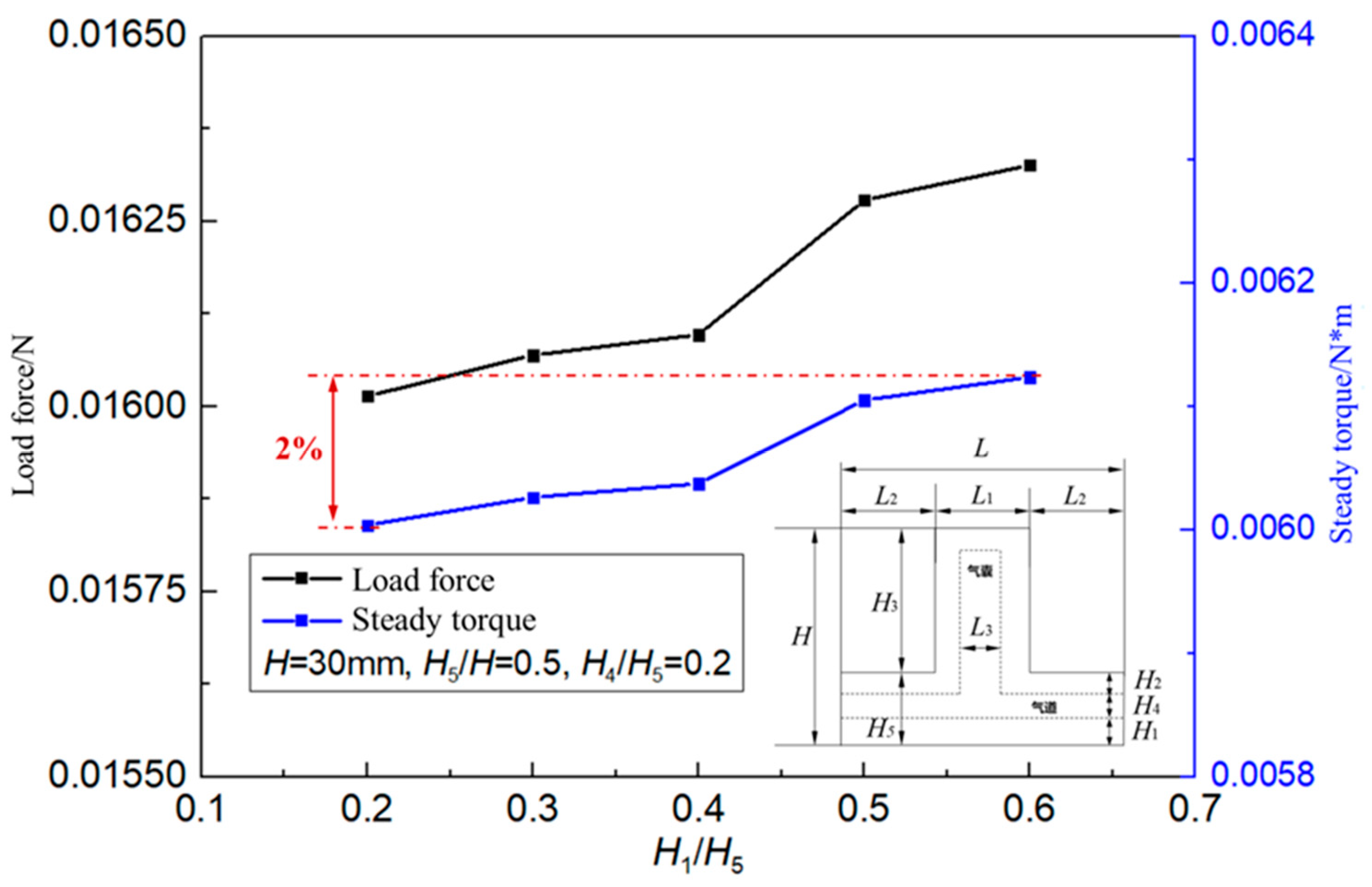
Previous studies on the shape of pneumatic network have confirmed that rectangular network actuators are not only easy to design and process, but also require less driving pressure and have good bending and response characteristics [15]. In this study, the rectangular network is selected as the research object. The structure and parameters of the calculation model are shown in Figure 1. The actuator consists of an upper actuator layer and a bottom layer. The upper actuator layer consists of a number of discrete individual actuators arranged in a linear manner. The air sacs are connected by a bottom airway. In the figure , K is a half of the depth of the actuator ( Z direction ) , L is the length of a single actuator unit ( X direction ) , L1 is the outer length of the actuator unit , L2 is the gap between adjacent actuators , L3 is the internal length of the actuator unit , H is the total height of a single actuator unit ( Y direction ) , H1 is the height of the underlying material , H2 is the height from the top of the airway to the outside top surface , H3 is the relative height of the outside top surface of the actuator unit , H4 is the height of the airway , and H5 is the height from the limiting layer to the outside top surface . In this study, K = 15mm and H = 30mm remained unchanged, and changes in L, L1、L3、H1、H3 and H4 explored the impact of the structure of the actuator on the load capacity. Table 1 is the simulation calculation variable table, and the structural parameters of the actuator are processed without dimension. The table shows the variation range of each variable in this study, as well as the reference value maintained by each variable when other variables change.
1.2. Calculation method
In this study, an actuator was first drawn by SolidWorks modeling according to the calculation model and simulation calculation variable table for understanding in ANSYS modeling. An actuator unit was first drawn, and then linear array extension was carried out. Finally, the two ends were sealed or reinforced. L2 was eliminated on both sides; The free end balloon wall extends along the Y direction to seal the airway. The fixed end of the airbag wall extends in the X direction, thickening and strengthening. ANSYS software is applied in this paper, and APDL language is used for modeling. Because of the symmetry of the model, half model is established in order to save calculational work, and tetrahedral mesh is used to divide the whole calculation model. According to the calculation of mesh convergence, the mesh size is chosen to be 1mm, and the number of model grids is about 1.58 million. The grid is shown in Figure 2.
This paper mainly studies the influence of structural parameters of software actuator on load capacity. Load capacity is defined as the maximum stabilizing torque of the software actuator end when the end of the software actuator and the root are at the same height. The fixed end of the actuator is set to a fixed constraint and the symmetrical surface applies a symmetric constraint. The actuator end constraint height direction displacement. A uniform pressure load is applied to the inside of the actuator to inflate the model gas pipe, and the pressure is set to 1kPa. The application of boundary conditions is shown in Figure 3.
The drive material is set as silicone material. Silicone material is a soft material, elongation in 500% ~ 1000%, with good tensile properties [22]. As can be found at the Figure 4 below, the silicone material is not a linear material, but when the tensile rate is less than 100%, the stress-tensile curve can be approximated as a linear relationship.
Due to the restriction of the end position shift, the deformation of the software actuator is small, which can be regarded as the linear elastic state. Therefore, the silica gel material can adopt the linear elastic constitutive, and the elastic modulus is E = 1MPa, μ = 0.49 [18] . The strain cloud diagram of the software actuator is shown in Figure 5, and the maximum elastic strain is 0.07. It can be seen that the silica gel material is still in the elastic stage.
1.3. Verification of calculation method
In order to verify the accuracy of the simulation model , a model consistent with previous experimental studies [15,18] was established , where L1 = 8mm , L2 = 1mm , L3 = 4mm , L = 10mm , H1 = 2mm , H2 = 1mm , H4 = 1mm , H5 = 4mm , H3 = 12mm , H = 16mm , and the number of actuator units N = 9 . Yeoh super elastic material constitutive model was adopted for the material model. The material parameters were set as C2 = 0.094MPa, C = 0.015, and 4kPa uniform pressure was applied in the actuator. The deformation of simulation results and test results is shown in the Figure 6 below. The maximum error of the free end of the actuator is about 5mm, and the relative error is 12.8%. The simulation results are basically consistent with the test, which indicates that the simulation results in this study are reliable.
2. Results and discussion
This section discusses the effect of actuator geometry on load capacity by analyzing the most important length and width factors of the actuator.
2.1. Influence of actuator length factor on load capacity
The influence of the actuator network unit length on L and the total actuator length Ltotal on the load capacity is shown in Figure 7. Set the ratio L / H to gradually increase from 0.3 to 1.25 and study the change of load force and steady torque with Ltotal . When Ltotal is unchanged, the load capacity of the actuator does not change monotonously with L, and the load capacity is optimized under the geometric structure L / H = 0.4. In other working conditions, the load capacity increases with the increase of Ltotal (the number of network N increases). L can be reasonably designed according to the simulation results to obtain the optimal load capacity. When L is constant, the load force of the drive decreases with the increase of Ltotal , and the steady torque fluctuates with the increase of Ltotal , but the overall trend is decreasing. This is because in the case of constant input pressure, with the increase of Ltotal , the stability of the drive decreases, Ltotal resulting in a decrease in load capacity. It can be concluded that in the case of similar overall structure, the load capacity (load force and steady torque) of the driver is mainly affected by ratio L / H, and Ltotal has a great influence on load force and almost no influence on stable moment.
The variation of the actuator load capacity with the outer length L1 of the actuator is shown in Figure 8. Set L = 15mm, L3 / L1 = 0.5 and N = 25 unchanged and study the change of load force and steady torque with ratio L1 / L. When the total length L of the actuator unit remains unchanged and the outer length L1 of the actuator increases, the load capacity of the actuator continues to decrease, with a reduction ratio of 29% . This is because with the increase of L1 the wall thickness ( 0.5 * ( L1 - L3 ) ) in the direction of the length of the actuator increases and the spacing of the actuator decreases, which will increase the rigidity of the actuator, resulting in the reduction of its deformability and ultimately the load capacity. The load capacity of the actuator as the outer length L1 of the actuator changes is shown in Figure 9. As can be seen from Figure 9, the maximum deformation of the actuator is 87mm when L1 / L = 0.3 , and 45mm when L1 / L = 0.8. The deformation decreases as ratio L1 / L increases, which further verifies that the rigidity of the actuator increases with the increase of ratio L1 / L.
The load capacity with the inner length L3 of the actuator is shown in Figure 10. Set L = 15mm, L1 / L = 0.5 and N = 25 unchanged and study the change of load force and steady torque with ratio L3 / L. When the outer length of the actuator L1 remains unchanged, the thickness of the actuator in the direction of length ( 0.5 * ( L1 - L3 ) ) decreases with the increase of L3 , the actuator interval spacing L2 remained unchanged, the stiffness of the actuator decreases, and the deformability of the actuator increases. The deformation change of the actuator with the inner length L3 of the actuator is shown in Figure 11. When L3 / L1 = 0.3, the maximum deformation of the drive is 48mm, and when L3 / L1 = 0.8, the maximum deformation of the actuator is 136mm. The load capacity of the corresponding driving force is increased, and the increase range reaches 46%. The deformation increases with the increase of L3 / L1 , which further verifies that the drive rigidity decreases with the increase of ratio L3 / L1 , resulting in the increase of deformation with the increase of ratio L3 / L1 .
2.2. Influence of actuator height factor on load capacity
The influence of the actuator load capacity on the relative height H3 of the outer top surface of the actuator is shown in Figure 12. Set H2 = H = 30mm and H4 / H = 0.1 unchanged and study the change of load force and steady torque with H3 / H . The variation of load force with H is complex. With the increase of H3 the load capacity increases first and then decreases, and the load capacity reaches the maximum value under the condition of H3 / H = 0.5. When the ratio H3 / H increases to 0.5 initially ( H3 / H = 0.2 ~ 0.5) , the size of the actuator unit increases, the stiffness of the actuator decreases, the deformability of the actuator increases, and the load capacity increases. However, when the ratio H3 / H continues to increase ( H3 / H = 0.5 ~ 0.8 ) , the actuator is just too low, and the grasping stability decreases, resulting in the load capacity of the actuator is reduced. The change of drive deformation with H3 is shown in Figure 13 . Figure 13 verifies that the deformation of the drive increases monotonically with the increase of ratio H3 / H , and the nonlinear change of the load capacity of the drive is caused by the low stiffness. In the subsequent drive structure design, it is necessary to design H to get the optimal design scheme.
The variation of actuator load capacity with actuator airway height H4 is shown in Figure 14. When the ratio H5 / H = 0.5 is constant, the load force load capacity decreases slightly with the increase of H4 , and the variation range is only 6.5%. This shows that the driving force load capacity is basically not affected by the actuator airway height H4 .
The actuator load capacity changes with the height H1 of the underlying material of the actuator as shown below. When H5 and H4 are fixed, the underlying material H1 increases the actuator load variation range by only 2% . This is due to the fact that while increasing H1 will increase the drive stiffness, it will lead to a reduction in the load capacity. However, the decrease of H2 in the process will make the driver more prone to deformability. The two factors interact with each other and the load carrying capacity of the drive in the final position is basically unchanged.
Figure 15.
The load capacity of the actuator varies with the height H1 of the underlying material of the actuator.
Figure 15.
The load capacity of the actuator varies with the height H1 of the underlying material of the actuator.
Conclusion
In this study, the finite element simulation method is used to study the influence of the height factor and the length factor of the soft actuator on the load capacity of the actuator, and the following conclusions are obtained:
( 1 ) With the increase of the total length of the actuator, the actuator stability decreases, the load capacity decreases, the load capacity increases first and then decreases with the length of the actuator unit, and there is an optimal load capacity design condition when L / H = 0.4;
( 2 ) The load capacity of the actuator decreases with the increase of the outer length of the actuator unit, and increases with the increase of the inner length of the actuator unit;
( 3 ) The deformation and grasping stability of the robot are affected by the relative height of the outer top surface of the actuator unit, and the optimal load capacity is obtained when H3 / H = 0.5;
( 4 ) The load capacity of the actuator is little affected by the height of the bottom layer and the height of the airway. The bottom height and the airway height can be designed according to the convenience of production when designing the soft manipulator.
References
- Kim, S., Laschi, C. , Trimmer B. Soft robotics : a bioinspired evolution in robotics [J]. Trends in biotechnology, 2013, 31, 287–294. [CrossRef]
- Rus, D., Tolley, M T. Design, fabrication and control of soft robots [J]. Nature. 2015, 521, 467–475. [CrossRef]
- Marchese, A.D., Onal, C.D., Rus, D. Autonomous soft robotic fish capable of escape maneu-vers using fluidic elastomer actuators [J]. Soft robotics. 2014, 1, 75–87. [CrossRef]
- Shepherd, R.F., Ilievski, F., Choi, W., et al. Multigait soft robot [J]. Proceedings of the national academy of sciences. 2011, 108, 20400–20403. [CrossRef]
- Cianchetti, M., Calisti, M., Margheri, L., et al. Bioinspired locomotion and gras** in water : the soft eight-arm OCTOPUS robot [J]. Bioinspiration & biomimetics. 2015, 10, 035003. [CrossRef]
- Xu Fengyu, Meng Fanchang, Fan Baojie, et al. Research review on Software Robot Drive , modeling and Application [J]. Journal of Nanjing University of Posts and Telecommuni-cations : Natural Science Edition. 2019, 39, 64–75.
- Wang Yanjie, Zhao Xin, Wang Jianfeng, et al. Research Progress of Soft Robot Drive Tech-nology [J]. Chinese Hydraulics & Pneumatics. 2023, 46, 1–11.
- Seok, S., Onal, C.D., Cho, K.J., et al. Meshworm : a peristaltic soft robot with antagonistic nickel titanium coil actuators [J]. IEEE/ASME Transactions on mechatronics. 2012, 18, 1485–1497. [CrossRef]
- Bartlett, N.W., Tolley, M.T., Overvelde, J.T.B., et al. A 3D-printed , functionally graded soft ro-bot powered by combustion [J]. Science. 2015, 349, 161–165. [CrossRef]
- Cianchetti, M., Ranzani, T., Gerboni, G., et al. STIFF-FLOP surgical manipulator : Mechanical design and experimental characterization of the single module [C]//2013 IEEE/RSJ interna-tional conference on intelligent robots and systems. IEEE, 2013, 3576-3581. [CrossRef]
- Marchese, A.D., Katzschmann, R.K., Rus, D. Whole arm planning for a soft and highly com-pliant 2d robotic manipulator [C]//2014 IEEE/RSJ International Conference on Intelligent Robots and Systems. IEEE, 2014, 554-560. [CrossRef]
- Polygerinos, P., Galloway, K.C., Savage, E., et al. Soft robotic glove for hand rehabilitation and task specific training [C]//2015 IEEE international conference on robotics and automation ( ICRA ). IEEE, 2015, 2913-2919. [CrossRef]
- Deng, M., Wang, A., Wakimoto, S., et al. Characteristic analysis and modeling of a miniature pneumatic curling rubber actuator [C]//The 2011 International Conference on Advanced Mechatronic Systems. IEEE, 2011, 534-539.
- Mosadegh, B., Polygerinos, P., Keplinger, C., et al. Pneumatic networks for soft robotics that actuate rapidly [J]. Advanced functional materials. 2014, 24, 2163–2170. [CrossRef]
- Fan Yi. Research and Application of Pneumatic Mesh Software Actuator [D]. Nanjing University of Aeronautics and Astronautics, 2020.
- Wang Ningyang, Sun Hao, Jiang Hao, et al. Research on Grasping Strategy of Software gripper based on Honeycomb Pneumatic Network [J]. Robot. 2016, 38, 371–377. [CrossRef]
- Jiang, H., Wang, Z., ** Y , et al. Hierarchical control of soft manipulators towards unstruc-tured interactions [J]. The International Journal of Robotics Research. 2021, 40, 411–434. [CrossRef]
- Bending Deformation Prediction Method for Pneumatic Mesh Soft Actuator [J]. ** Me-chanical Engineering. 2020, 31, 1108.
- Su iyi , Xu Qiping , Liu Jinyang. Theoretical Modeling , Simulation Analysis and Experi-mental Research of Pneumatic toothed Software Actuator [J]. Journal of Shanghai Jiao Tong University. 2023, 57, 1016.
- Xu Qiping , Liu Jinyang. Modeling and Simulation of multi-cavity pneumatic Soft Actuator [J]. Journal of Shanghai Jiao Tong University. 2020, 54, 551.
- Fei Yanqiong , Pang Wu , Yu Wenbo. Research on Motion of Pneumatic Driven Soft Robot [J]. Journal of Mechanical Engineering. 2017, 53, 14–18.
- Liu Yuchao. Research on Cavity Type Pneumatic Soft Arm [D]. Harbin Institute of Tech-nology, 2020.
Figure 1.
Schematic diagram of the structure of the calculation model.
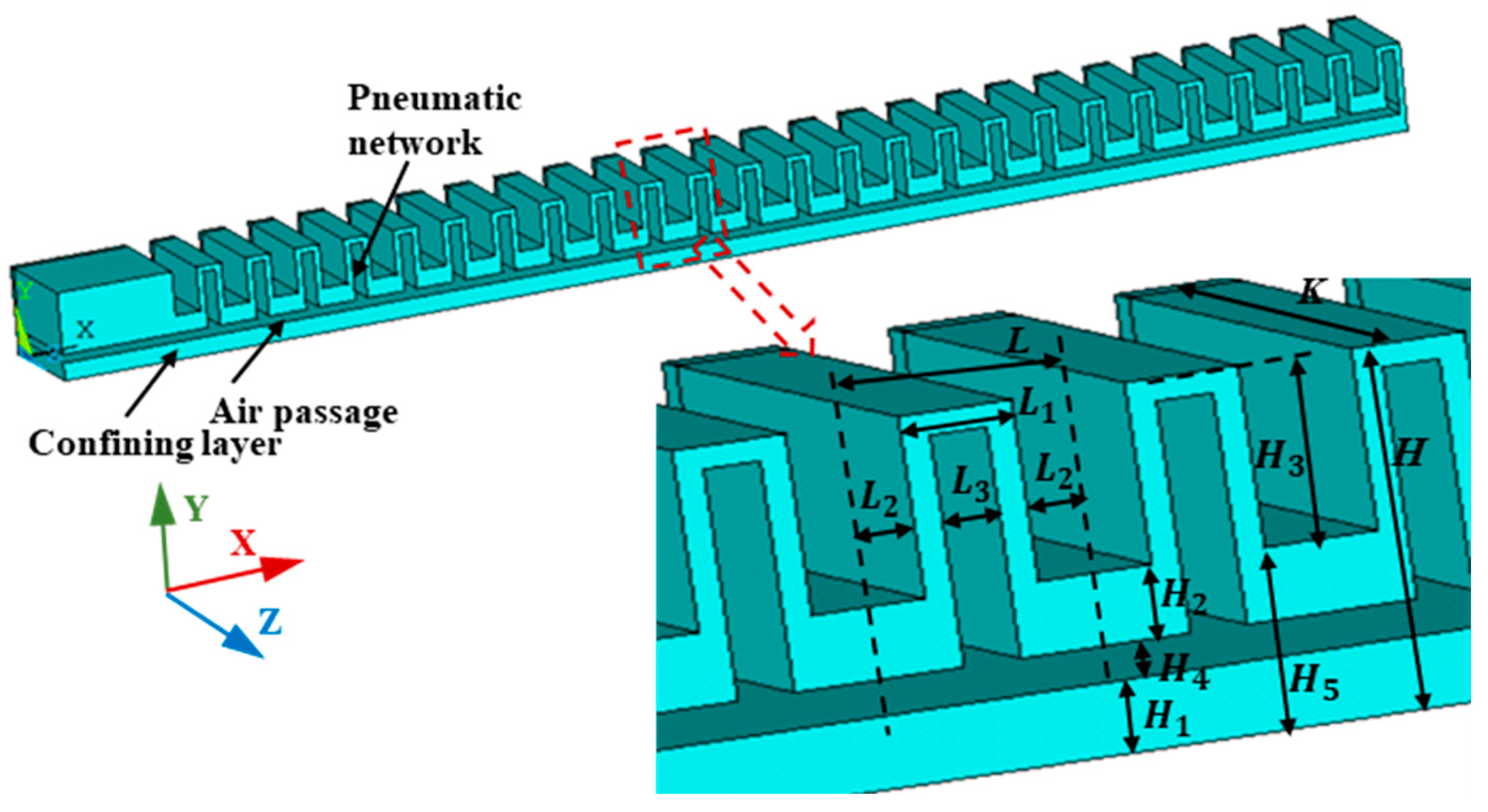
Figure 2.
Finite element discretization of software actuator.
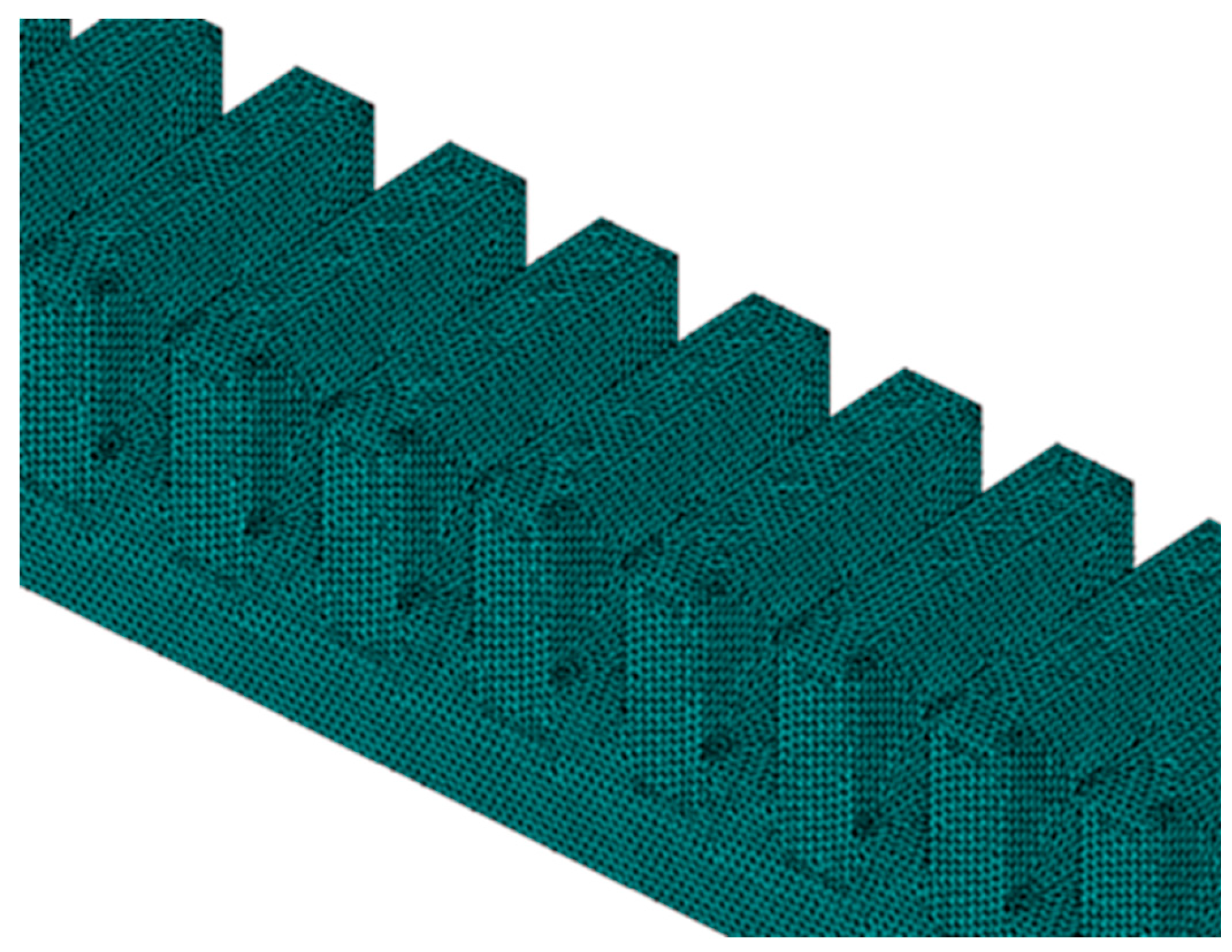
Figure 3.
Application of boundary conditions.
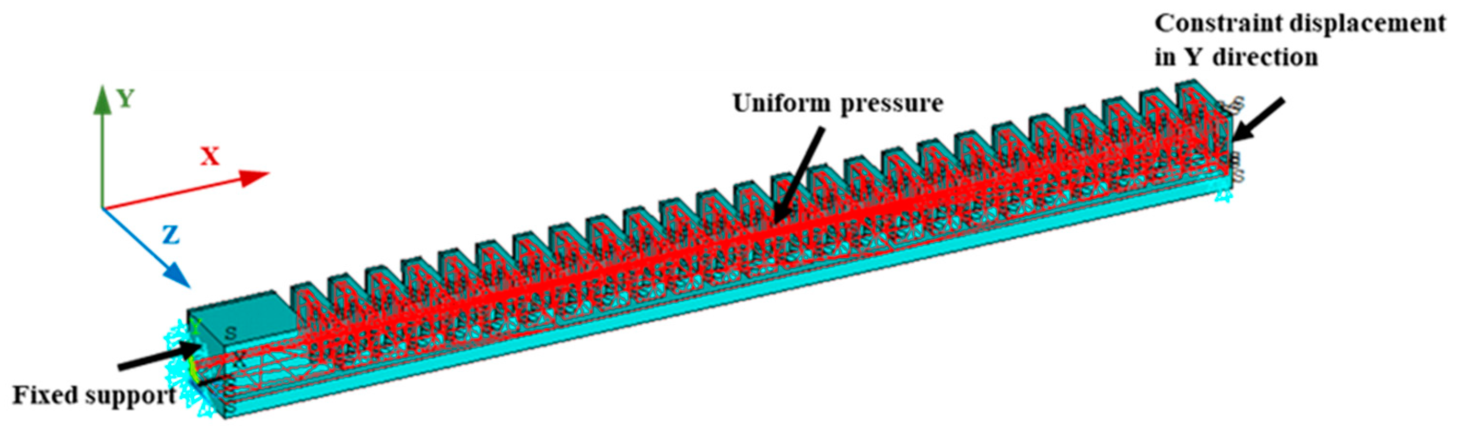
Figure 4.
stress-tensile curve of silica gel material.
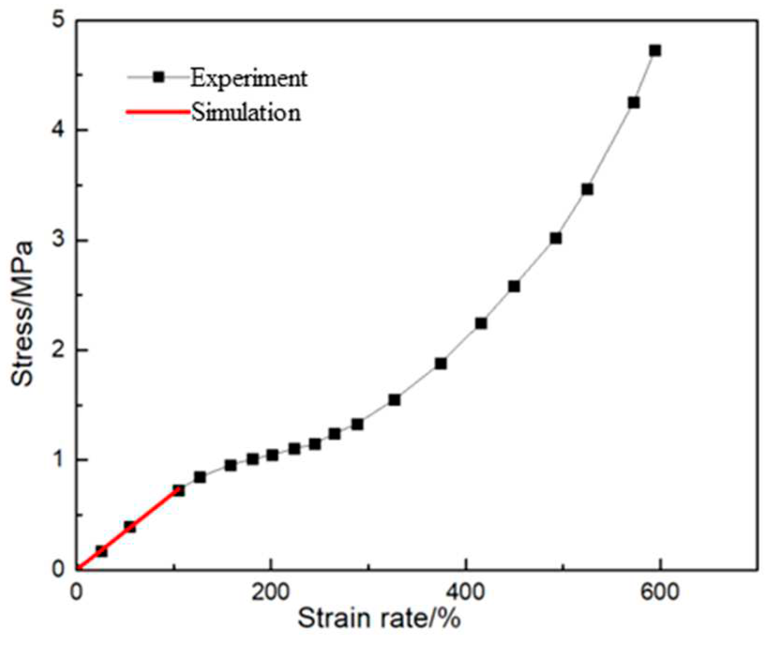
Figure 5.
Strain cloud diagram of the software actuator.
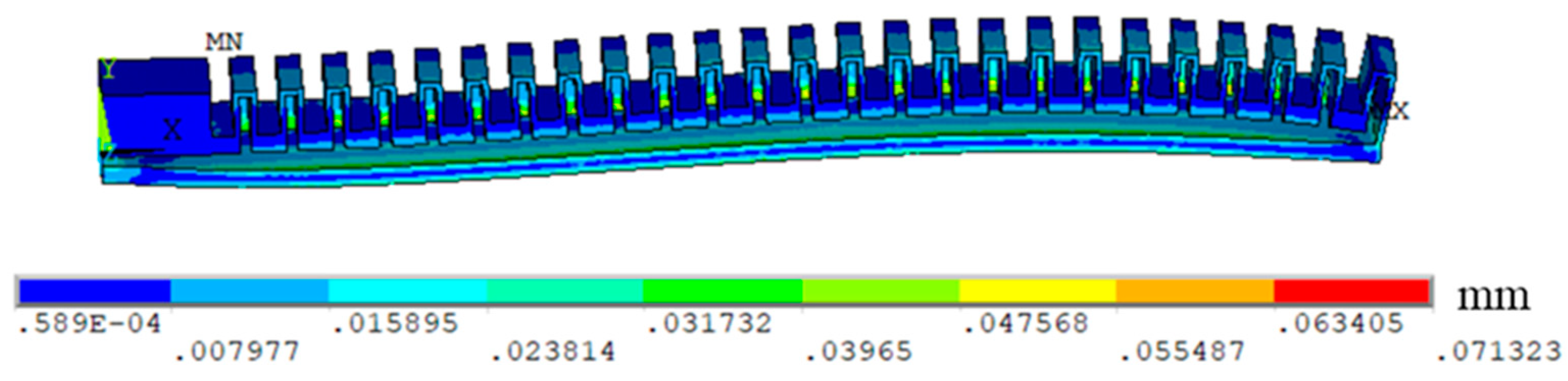
Figure 6.
Comparison between simulation calculation and experimental results.
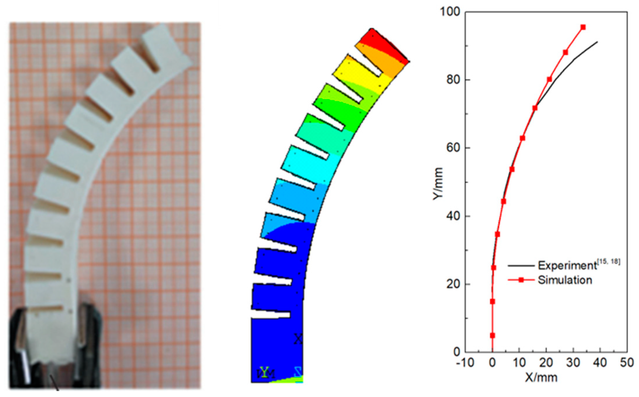
Figure 7.
How the load capacity of the actuator varies with Ltotal and L.
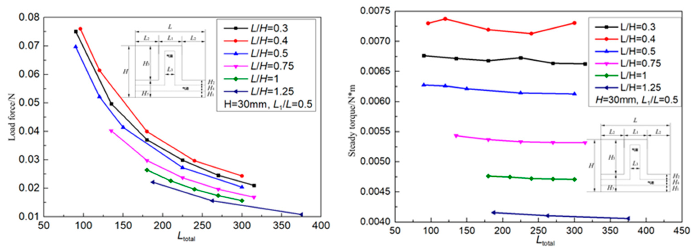
Figure 8.
The load capacity of the actuator changes with the outer length L1 of the actuator.
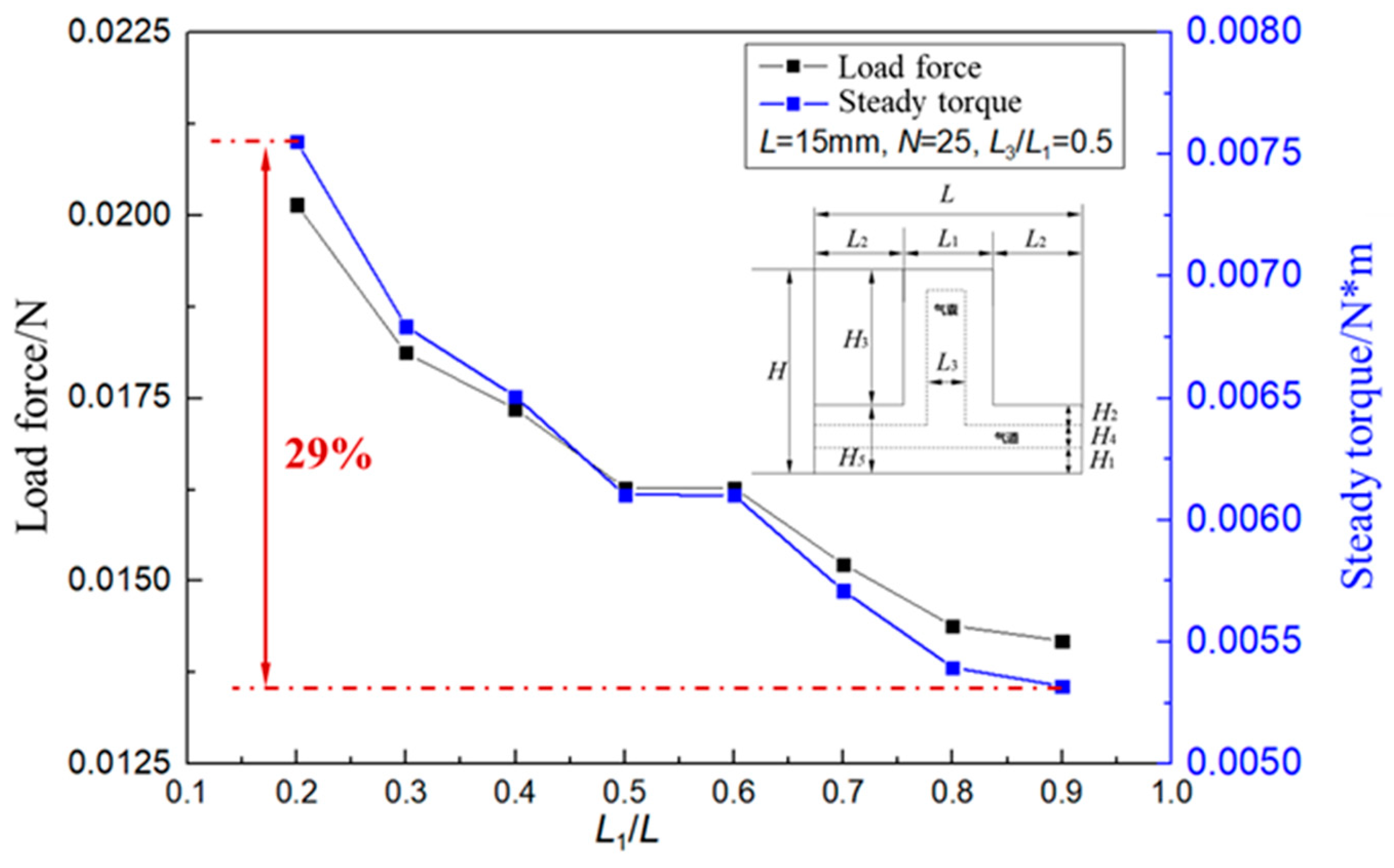
Figure 9.
Actuator deformation with the outer length L1 of the actuator.
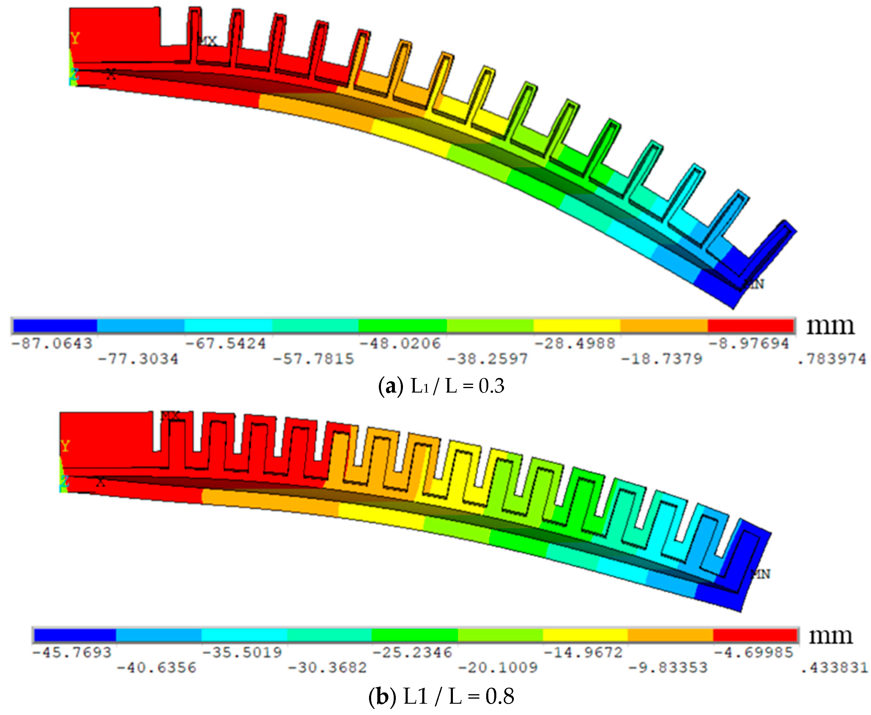
Figure 10.
The load capacity of the actuator varies with the length L3 inside the actuator.
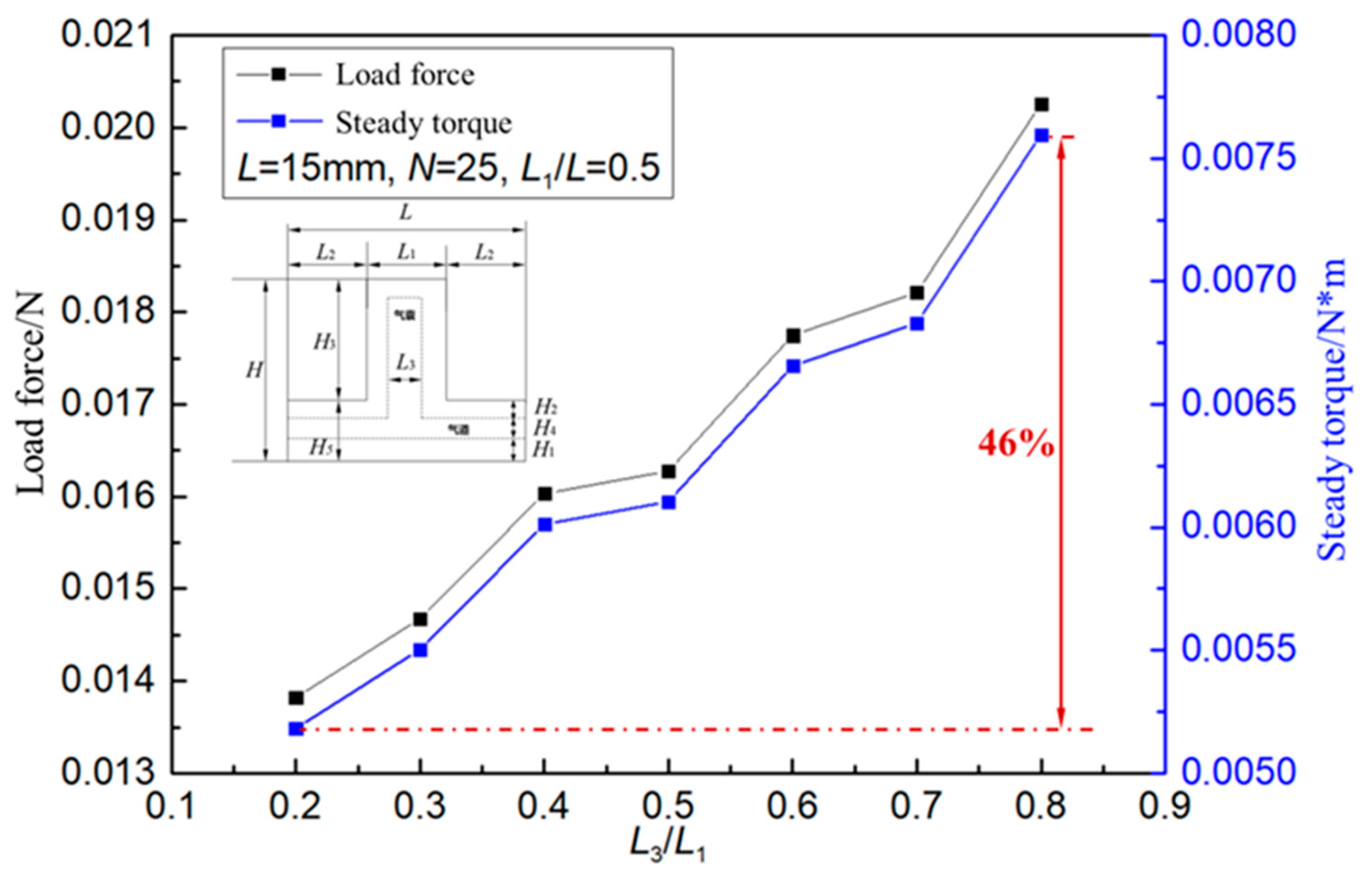
Figure 11.
Change of actuator deformation with outer length L3 of actuator.
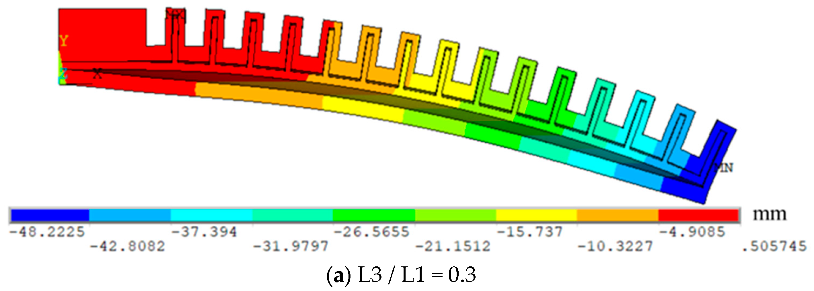
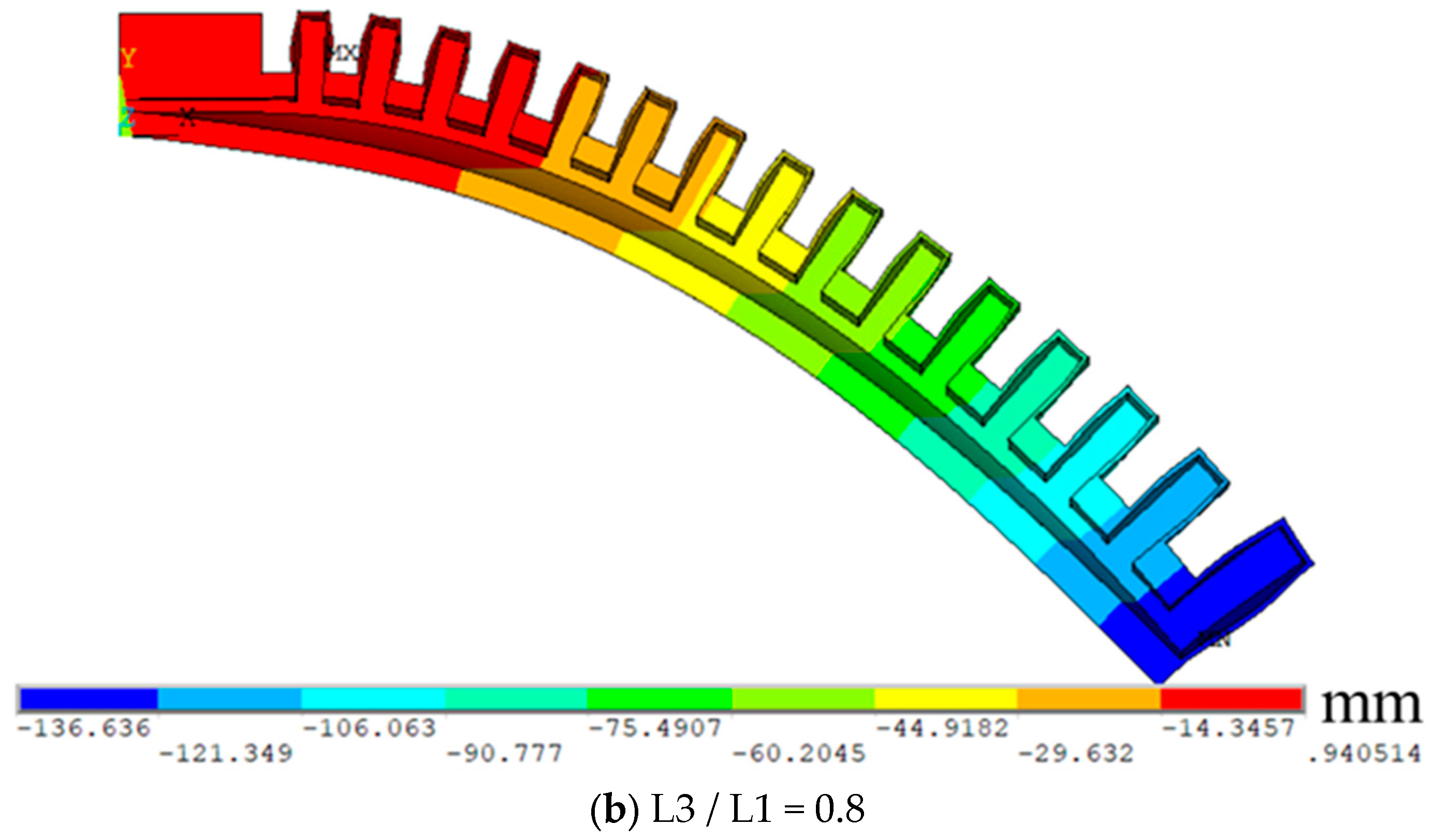
Figure 12.
The load capacity of the actuator varies with the relative height H3 of the outer top surface of the actuator.
Figure 12.
The load capacity of the actuator varies with the relative height H3 of the outer top surface of the actuator.
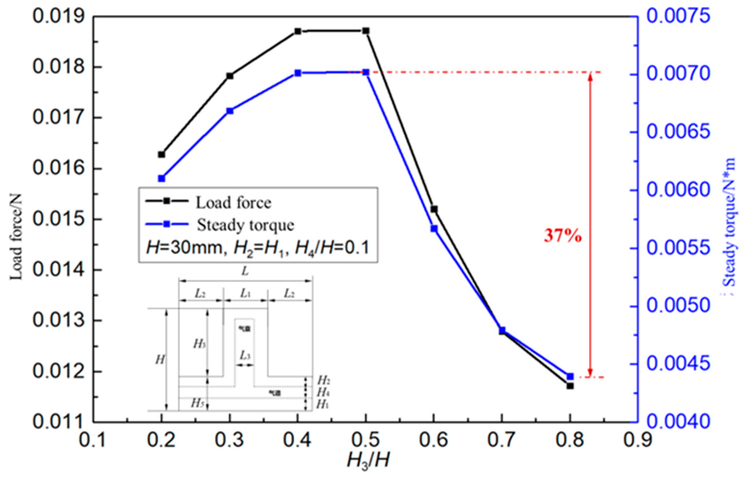
Figure 13.
The change of actuator deformation with the relative height H3 of the outer top surface of the actuator.
Figure 13.
The change of actuator deformation with the relative height H3 of the outer top surface of the actuator.
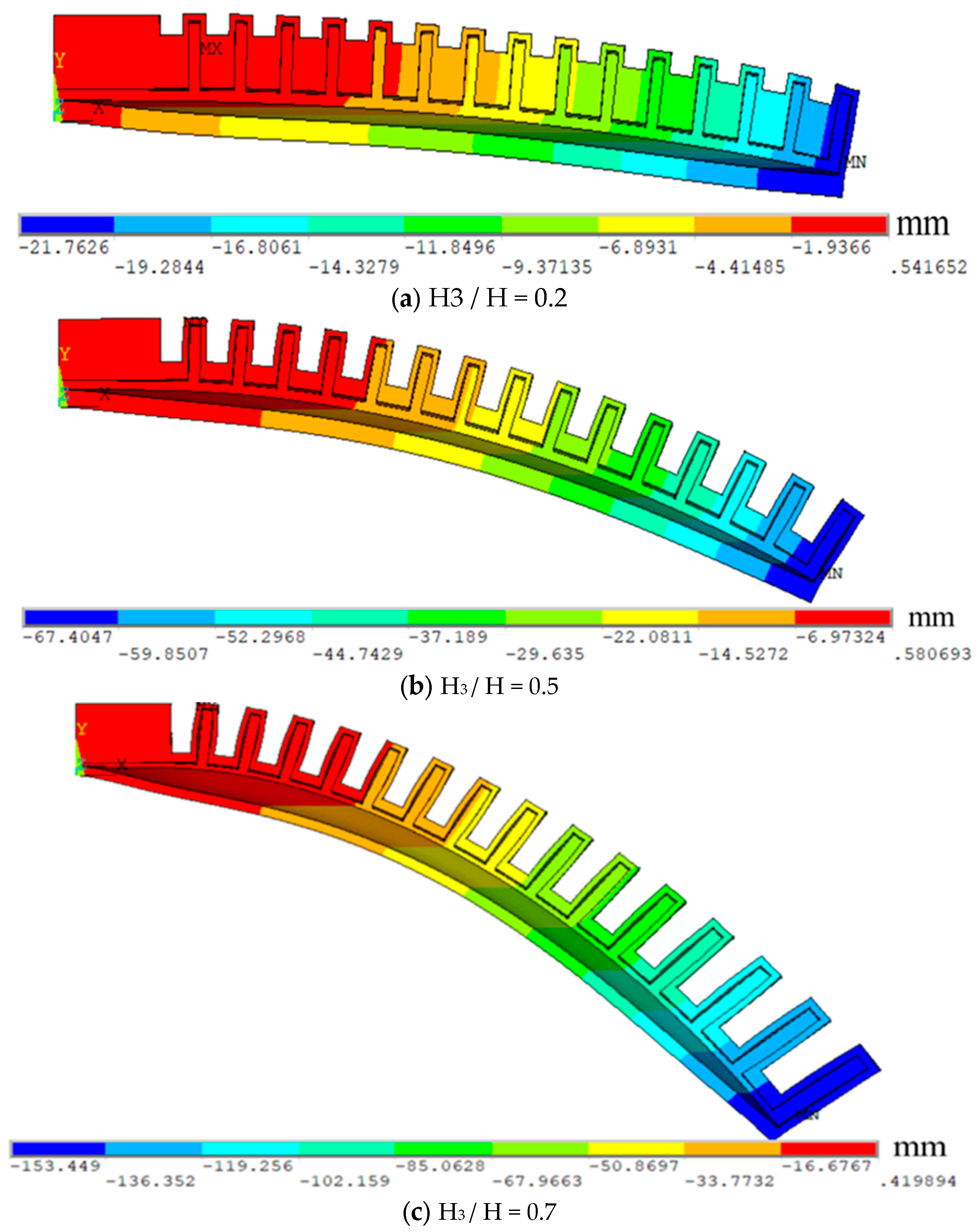
Figure 14.
How the load capacity of the actuator changes with the height of the actuator airway H4.
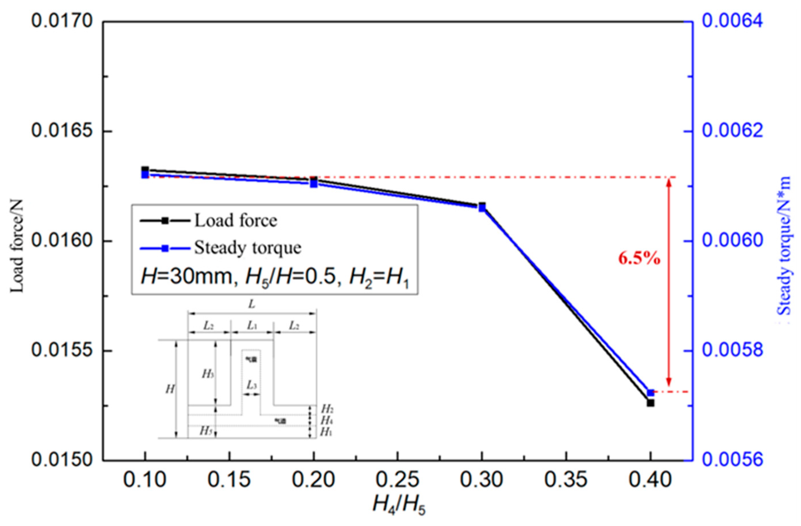

Table 1.
Simulation calculation variable table.
| Variable parameters | Variable value range | Base value |
|---|---|---|
| Actuator unit dimensionless length L / H |
0.3 ~ 1.25 | 0.5 |
| The outer side of the actuator has no dimensional length L1 / L | 0.2 ~ 0.9 | 0.5 |
| No dimensional length L3 / L inside the actuator | 0.2 ~ 0.8 | 0.5 |
| The outer top surface of the actuator has an infinite relative height H3 / H | 0.2 ~ 0.8 | 0.5 |
| Actuator airway dimensionless height H4 / H5 | 0.1 ~ 0.4 | 0.5 |
| Actuator bottom layer dimensionless height H1 / H5 | 0.2 ~ 0.6 | H1 / H2 = 1 |
Disclaimer/Publisher’s Note: The statements, opinions and data contained in all publications are solely those of the individual author(s) and contributor(s) and not of MDPI and/or the editor(s). MDPI and/or the editor(s) disclaim responsibility for any injury to people or property resulting from any ideas, methods, instructions or products referred to in the content. |
© 2024 by the authors. Licensee MDPI, Basel, Switzerland. This article is an open access article distributed under the terms and conditions of the Creative Commons Attribution (CC BY) license (http://creativecommons.org/licenses/by/4.0/).
Copyright: This open access article is published under a Creative Commons CC BY 4.0 license, which permit the free download, distribution, and reuse, provided that the author and preprint are cited in any reuse.


