
Submitted:
16 December 2025
Posted:
17 December 2025
You are already at the latest version
Abstract
This paper introduces a novel Magnetorheological (MR) damper integrating a ball-screw mechanism (SMRB damper), designed to unify translational and rotational motion for enhanced automotive suspension performance. While shear-mode rotary MR dampers offer excellent responsiveness and stability, prior designs face persistent issues such as high off-state torque, structural complexity, or limited damping force. The proposed damper aims to overcome these limitations. Its design and operating principle are presented, followed by the development of a mathematical model based on the Bingham-plastic formulation and finite element analysis. To maximize damping capability, the key structural parameters are optimized using an Adaptive Particle Swarm Optimization (APSO) algorithm. Finally, a prototype is fabricated based on the optimized results, and experimental tests validate its performance against simulation predictions, demonstrating its improved potential for vibration control applications.
Keywords:
magnetorheological fluid (MRF)
; magnetorheological damper
; MR brake
; ball-screw mechanism
; parameter optimization
1. Introduction
Over the past decade, advances in vibration control have become increasingly vital for automotive suspension systems, which must mitigate vibrations to ensure safety and passenger comfort. Magnetorheological (MR) dampers have emerged as a leading solution, offering high damping force, precise controllability, and effective adaptation to varying conditions through the use of MR fluids [1,2,3,4]. Researches have focused on three primary operating modes: flow, shear, and valve mod. Among these, shear and valve modes receiving the most practical attention, especially for MR dampers [5,6,7]. Each mode presents distinct trade-offs: valve mode is structurally simple and easily controlled but suffers from pressure drops and response delays; flow mode produces large damping forces but has high initial resistance, limiting sensitivity. In contrast, shear mode provides smaller damping forces but superior responsiveness, sensitivity, and stability, making it a particularly promising approach for advancing suspension system performance.
Several recent studies have focused on rotary MR dampers operating in shear mode. Sun et al. [8] examined a rotary MR damper integrated into a seat suspension system for heavy-duty vehicles. Their experimental results demonstrated that the damper delivered performance comparable to that of linear MR dampers. However, the structural design had not yet been optimized to improve efficiency or reduce the off-state torque at 0 A. Bai et al. [9] developed a multi-disc rotary MR damper intended for seat suspensions with a parallelogram mechanism. Although effective, this damper featured a large structure and high energy consumption, limiting its suitability to systems with fixed layouts and making it impractical for installations requiring compactness or design flexibility. Yu et al. [10] introduced a rotary MR damper employing a helical flow configuration that enabled operation in both flow and shear modes, resulting in a more compact design than traditional shear-mode dampers. Following this, an enhanced rotary MR damper comprising two passive discs and one active disc was proposed, allowing precise adjustment of damping force and stiffness [11]. Experimental validation confirmed its ability to regulate angular stiffness with clear dependence on rotational angle, torque, and current. Although the issue of low damping torque density was addressed, the device still suffered from structural complexity and manufacturing challenges. Park et al. [12] developed a rotary MR damper for low-floor vehicles with semi-active suspension. The prototype exhibited rapid response and achieved a high damping torque of 600 Nm, slightly below the simulated value of 744.8 Nm; however, the off-state torque remained undesirably high. Similarly, Zhu et al. [13] designed a compact rotary MR damper integrated with a bearing, but the output torque was found to be unstable during rotation. Ehab et al. [14] optimized a rotary MR damper for torsional vibration control, demonstrating its effectiveness. Nevertheless, the design was susceptible to a magnetic bottleneck effect and performance degradation due to temperature variation during operation. To address the bottleneck issue, Zuo et al. [15] proposed a rotary MR damper with a T-shaped rotor for seat suspension applications. Although this configuration improved certain aspects of magnetic flux distribution, it had not yet been fully optimized to enhance overall performance or reduce the brake volume. Moreover, the maximum damping force achieved for seat suspension applications was only about 320 N, indicating room for further improvement.
Although numerous studies have investigated MR dampers, none have integrated both translational and rotational motions to enhance performance and adaptability, especially for vehicle suspension application. To overcome this limitation, the present work introduces a novel ball-screw-based configuration, referred to as the SMRB damper, with its structural design and operating principles described in Section 2. Section 3 develops the mathematical model of the SMRB damper using the Bingham plastic formulation in conjunction with finite element analysis. To further increase the damping capability, an optimization problem is established and solved using the Adaptive Particle Swarm Optimization (APSO) algorithm, as detailed in Section 4. Finally, based on the optimized parameters, experimental evaluations are conducted to assess the damper’s performance and compare it with the simulation results.
2. Working Principles and Modeling of SMRB Damper
Figure 1 presents the structural layout of the proposed SMRB damper. The system is composed of a ball-screw assembly, a magnetic rotor sleeve, a magnetic stator housing, and two copper coils positioned inside the housing. To prevent fluid leakage and maintain reliable performance, the design incorporates two lip seals along with a set of thrust ball bearings. The annular space between the housing and the sleeve is filled with MRF. Once an electrical current is supplied to the coil, the MRF within this region generates a resisting torque, acting similarly to a magnetic braking system. This torque is then transformed into a linear damping force through the action of the ball-screw mechanism. In this design, the coil is positioned above the separator to prevent the magnetic field from directly interacting with the MRF, thereby simplifying maintenance and assembly procedures. Furthermore, the rotor is engineered with a double-tooth configuration, which increases torque output and enhances the damper’s capacity to generate damping force.
Understanding the magnetic field distribution within the SMRB damper is essential for interpreting the behavior of the MR damper. Accurate modeling of the magnetic circuit requires detailed information regarding its geometry, material characteristics (B–H curves), mesh configuration (element type and size), applied current, and relevant boundary conditions. A simplified representation of the magnetic circuit is provided in Figure 1b. The dimensional parameters are divided into three categories: design variables, which can be adjusted during the optimization process; fixed variables, which remain unchanged; and dependent variables, which are determined based on the first two groups. The outer surfaces of the housing are defined as magnetic boundaries, ensuring that the magnetic flux lines remain parallel at these edges. The magnetic circuit is analyzed using the finite element method (FEM) implemented in ANSYS. For this purpose, a quadrilateral axisymmetric element (PLANE13) in ANSYS APDL is selected, as illustrated in Figure 2. The resulting magnetic flux density distribution and field lines obtained from the simulation are shown in Figure 3. Magnetic components such as the housing, made of C45 steel, are assigned their respective B–H curves to capture their nonlinear magnetic behavior. Conversely, non-magnetic parts—including the copper coil and the intermediate pole constructed from non-magnetic stainless steel—are modeled with a relative permeability of 1.0, identical to that of air. The resistivity of the copper used in the coil is denoted as . Furthermore, this study employs a commercial MR fluid (MRF132-DG) supplied by LORD Corporation. The magnetic behavior of the MRF is characterized using its corresponding B–H curve, as described in [16,17,18].
To investigate the behavior of the MRF in the operating gap, the distribution of magnetic flux density, which varies spatially, must be assessed. The average magnetic flux density across the MRF gap is therefore calculated by integrating the flux along path P1 to P7, as illustrated in Figure 3b.
The evaluation of the SMRB damper’s damping force begins with the operating principle of the ball-screw mechanism, where the axial load applied to the screw dictates the motion of the nut. This load causes the balls to roll along the helical groove, generating a torque that drives the nut’s rotation. The magnitude of this rotational motion depends on both the applied axial load and the geometry of the screw, enabling high accuracy and efficiency in power transmission. To ensure effective mitigation of external disturbances, the maximum damping force is defined to correspond to the maximum external load, thereby contributing to system stability and operational safety. The resulting motion is influenced not only by the screw’s lead angle and friction angle but also by additional resistive components. Specifically, the damping torque is produced by the MR fluid in the annular gap when subjected to magnetic excitation, along with frictional contributions from the lip seal and the thrust bearings. The relationship between the generated damping force and the corresponding damping torque is thus established based on the mechanical transformation provided by the ball-screw mechanism [19,20]:
and are respectively the lead angle and the replacement rolling friction angle, which are determined by the following equation:
Where, Db is the ball circle diameter,is the contact angle, ft friction coefficient, p is the screw lead, d1 is screw inner diameter.
The damping torque produced by the MRF is evaluated under the assumption of a linear velocity distribution across the MRF gap, while its rheological behavior is described using the Bingham plastic model. Accordingly, the damping torque (Td) of the SMRB damper can be expressed as:
Where, TMR, Tls, and Tbr are respectively the friction torque of MRF, lip-seal and thrust ball bearing (Nm). The friction torque components on above equation are determined by the following formulas [21,22,23,24]:
Here, Rf denotes the outer radius of the magnetic core cluster fixed on the sleeve, La is the length of the magnetic core,andare respectively the yield stress and post-yield viscosity of the MRF, the thrust ball bearing friction depends on rotational speed (n), oil kinematic viscosity (v), axial load (Fa), and bearing average diameter (db), coefficient of sliding friction.
3. Optimal Design and Results of SMRB Damper
In this section, the optimization of the SMRB damper is addressed with respect to two key objectives: achieving the required damping force and reducing the overall size. The damping force (Fd) must reach a predetermined target and is highly dependent on the damper’s geometric parameters. Accordingly, these parameters are adjusted to ensure that the desired damping force is obtained while simultaneously reducing the damper’s mass (Md) and overall production cost. In essence, the geometry is refined to maintain adequate damping performance while minimizing structural weight. The objective function and constraints are expressed as follows:
Maximum:
Subjected to:
Here, Vf, Vbs, Vc, Vh, and VMR denote the volumes of the sleeve, ball-screw mechanism, coils, housing, and MR fluid of the SMRB damper, respectively. are represent the densities of the materials corresponding to the previously mentioned components, respectively.
The design variables (DVs) of the SMRB damper are defined, with the primary structural dimensions selected for optimization. These include parameters such as the sleeve thicknesses (tf, Lt, tt, Lc), separator thickness (ts), coil dimensions (wc, hc), housing thickness (to), core lengths (Li, Lo), and the MRF gap (tg). A critical design consideration is that a smaller MRF gap increases the friction torque and consequently enhances the damping force. However, excessively reducing the gap also raises manufacturing challenges and requires higher precision during machining. Therefore, the MRF gap is selected within a practical and feasible range of 0.8–1.5 mm.
To solve the optimization problem, several conventional methods—such as Newton’s method, the Newton–Raphson technique, Sequential Quadratic Programming, and Gradient Descent—have been employed in previous studies [25,26,27]. Although these approaches can be effective in certain scenarios, they are typically sensitive to initial conditions and often converge prematurely to local optima. To overcome these limitations, the Adaptive Particle Swarm Optimization (APSO) algorithm is adopted in this work. APSO maintains the simplicity and low computational demand of standard PSO while significantly improving performance through dynamic parameter adaptation. In APSO, population diversity is assessed using the average distance between all particles and the global best position. This distance is normalized into a convergence index (Et), which serves as the basis for continuously adjusting the inertia weight and learning factors. Through this adaptive mechanism, APSO achieves an effective balance between exploration and exploitation, enabling it to avoid entrapment in local minima and enhance convergence speed toward the global optimum [28]. In the study, APSO is implemented in MATLAB and integrated with ANSYS APDL to obtain the optimal damper design. The previously defined design variables are used in the optimization process, with the maximum number of iterations set to imax = 50 and the population size specified as N = 70. The adaptive adjustment of inertia weight and learning coefficients ensures that APSO maintains robust search capability throughout the optimization process. Specifically, a sigmoid-based mapping w(Et), with, serves as an efficient approach to adapt the inertia weight based on the swarm’s evolutionary progress [29,30]:
Where, ; APSO uses the average distance between the global best solution and the other particles to evaluate the population, which is expressed as follows: [30].
This study employs a 24-gauge copper coil wire with a 0.511 mm diameter and a current-carrying capacity of up to 3 A. For operational safety, the current is limited to a maximum of 2.0 A. The SMRB damper design utilizes a filling ratio of 0.7. Furthermore, based on prior experimental data, an energy loss of approximately 10% is accounted for, primarily attributed to magnetic losses from hysteresis and eddy currents. Figure 4a and Figure 4b present the objective and constraint conditions, as well as the magnetic flux distribution at the optimal solution. As shown in Figure 4a, the optimization converges at the 19th iteration. At this optimal point, the mass of the SMRB damper is reduced substantially—from an initial 2.23 kg to 1.42 kg. Meanwhile, the damping force achieves 1500.87 N, satisfying the requirement of being no less than 1500 N. Compared with the initial design, which produced a damping force of 1345.17 N, the optimized configuration results in a noticeable reduction in force output. Figure 4b further shows that the magnetic flux density within the MRF gap at the optimal design is also significantly lower than that obtained using the unoptimized parameters. Despite this reduction, the optimized structure is markedly more compact and efficient than the initial design. At the optimal point, the off-state force (Fd0), representing frictional resistance in the absence of an applied magnetic field, is determined to be 104.51 N. The magnetic flux density along the MRF gap segments reaches approximately 0.191 T. In the region of the gap located beneath the separator, the flux density increases significantly, reaching up to 0.55 T. Owing to this higher magnetic flux density, the area beneath the separator contributes substantially to the generation of torque. The magnetic core of the optimized SMRB damper has a length of 30 mm and a radius of 46.45 mm. A comprehensive summary of the final optimal parameters and performance characteristics is provided in Table 1.
4. Experiments and Results
Using the optimized parameters listed in Table 1, a detailed 3D prototype of the SMRB damper was constructed in Siemens NX12, as illustrated in Figure 5. The model is divided into four main components—the inner housing, outer housing, magnetic core, and ball-screw mechanism—to facilitate straightforward assembly, fabrication, and maintenance. The complete prototype measures 110 mm in length and 75 mm in diameter, while the magnetic core has dimensions of 30 mm in length and 92.9 mm in diameter. The damper is designed for a functional stroke of 75 mm; however, to ensure operational safety and prevent potential contact that could damage the magnetic core, the maximum allowable stroke is limited to 80 mm. During assembly, the sleeve is rigidly connected to the nut of the ball-screw mechanism, forming an integrated rotor unit. The annular gap between the sleeve and the inner housing is filled with MRF. The coils are directly wound around the inner housing, whereas the outer housing functions as the magnetic yoke, completing the magnetic circuit when the field is generated inside the SMRB damper. It is also important to note that the two coils are supplied with currents flowing in opposite directions.
Figure 6 presents the experimental setup for evaluating the proposed SMRB damper. In this configuration, a crank–slider mechanism is used to generate the linear reciprocal motion, driven by a 500 W-AC motor with gearbox. The system can produce a maximum axial force of 2000 N at a velocity of 0.15 m/s. The excitation frequency of the test system, adjustable within the range of 0 to 0.7 Hz, is controlled using a Mitsubishi D740 frequency inverter. The damping force is measured by a PST–Keli load cell (300 kg capacity), with its output signal amplified before acquisition. Together with the displacement data obtained from the LVDT sensor, both signals are captured through an NI-6002 data acquisition card and subsequently processed in LabVIEW. A PPW-8011 programmable power supply is employed to deliver the input current to the SMRB damper prototype. Additionally, the Denoising Wavelet feature in LabVIEW is used to suppress measurement noise, thereby improving the precision and reliability of the recorded data.
In the experimental procedure, the power supply was manually adjusted to deliver various current levels to the MR damper, allowing the corresponding damping force outputs to be observed and evaluated. Under a displacement excitation with an amplitude of 37.5 mm and a frequency of 0.5 Hz, the resulting damping force–displacement characteristics were recorded and are shown in Figure 7a. The results reveal that the damping force increases in proportion to the applied current, confirming the current-dependent behavior typical of the SMRB damper prototype. As the current rises, the damping force–displacement loops broaden symmetrically along the displacement axis, illustrating the damper’s capacity to absorb and dissipate kinetic energy effectively. The experimental data show that the peak damping force reaches approximately 1417 N at an input current of 2 A, which is slightly lower than the theoretical optimum value of 1500.87 N. This deviation may arise from several factors, including non-uniformity of the MRF, localized magnetic saturation, fabrication tolerances, and discrepancies between simulated and actual material properties. Despite these differences, the experimental findings validate the damper’s ability to deliver adjustable damping and efficient energy dissipation, demonstrating its suitability for applications requiring variable damping performance under diverse loading and frequency conditions.
Figure 7b presents the force–velocity characteristics of the SMRB damper, showing a pronounced increase in damping force as the input current rises from 0 A to 2 A. The curves display a nonlinear hysteretic behavior: at low piston velocities, the response is dominated by yield stress, whereas viscous effects become increasingly significant as the velocity increases. The magnitude of the damping force expands from approximately ±142 N at 0 A to nearly ±1417 N at 2 A, with a noticeable trend toward saturation at higher current levels. These results confirm the damper’s capability for controllable damping and its effectiveness in dissipating energy across a range of operating conditions.
Figure 8 illustrates the output damping force of the SMRB damper under sinusoidal displacement excitation. Across frequencies of 0.4 to 0.7 Hz at a constant 2.0 A current, the damping force exhibits only a minor increase. Notably, the shape and enclosed area of the force-displacement hysteresis loops show negligible variation with frequency. This suggests that the viscous damping component, attributable to the MRF’s apparent viscosity, contributes minimally to the total force. Instead, the damper's dynamic response is governed primarily by the yield-stress-related shear force of the MRF. Consequently, the SMRB damper demonstrates stable, frequency-insensitive damping performance, affirming its suitability for applications requiring reliable operation across varied conditions.
5. Conclusions
In this study, a novel rotary MR damper is proposed as an alternative to conventional configurations, aiming to enhance performance in both translational and rotational motions while reducing initial magnetic resistance. Drawing upon an extensive review of previous research and its associated limitations, a new structural concept was formulated and further supported by the design and modeling of an MRF sealing mechanism. To improve overall effectiveness, finite element analysis was conducted, and the SMRB damper was optimized through the integration of MATLAB and ANSYS APDL using the Adaptive Particle Swarm Optimization (APSO) algorithm. The optimized model achieved a maximum damping force of 1500.87 N with a compact total mass of 1.42 kg. Following the optimization stage, a physical prototype of the SMRB damper was manufactured and experimentally evaluated to examine the relationship between input current and resulting damping force. The experimental findings show that the prototype produced a peak damping force of 1417 N at 0.5 Hz under an applied current of 2 A, corresponding to 94.46% of the optimal value predicted by simulation. Further tests conducted across multiple excitation frequencies confirmed a characteristic nonlinear response with pronounced hysteresis loops. These results not only demonstrate the stable and effective performance of the proposed damper but also validate the practical feasibility of the SMRB configuration for applications requiring dependable vibration control under a wide range of dynamic loading conditions.
Author Contributions
Conceptualization, Hieu Minh Diep and Quoc Hung Nguyen; methodology, Zy Zy Hai Le and Quoc Hung Nguyen; software, Hieu Minh Diep and Zy Zy Hai Le; validation, Hieu Minh Diep, Bao Tri Diep and Zy Zy Hai Le; formal analysis, Zy Zy Hai Le and Quoc Hung Nguyen; investigation, Hieu Minh Diep and Zy Zy Hai Le; resources, Bao Tri Diep; data curation, Hieu Minh Diep and Bao Tri Diep; writing—original draft preparation, Hieu Minh Diep; writing—review and editing, Zy Zy Hai Le and Quoc Hung Nguyen; visualization, Hieu Minh Diep and Bao Tri Diep; supervision, Zy Zy Hai Le; project administration, Quoc Hung Nguyen; funding acquisition, Quoc Hung Nguyen. All authors have read and agreed to the published version of the manuscript.
Data Availability Statement
The data supporting the findings of this study are available from the corresponding author upon reasonable request. Due to confidentiality obligations and the protection of participant privacy, the dataset is not openly accessible. Interested researchers may request access to the data by contacting the corresponding author at: nq.hung@hutech.edu.vn or nguyenhung2000vn@yahoo.com.
Conflicts of Interest
The authors declare no conflicts of interest.
Abbreviations
The following abbreviations are used in this manuscript:
| APSO | Adaptive Particle Swarm Optimization |
| LVDT | Linear Variable Differential Transformer |
| MR | Magneto-Rheological |
| MRF | Magneto-Rheological Fluid |
| SMRB | Screw-Magneto-Rheological-Brake |
References
- Ahamed, R.; Choi, S.B.; Ferdaus, M.M. A state of art on magneto-rheological materials and their potential applications. Journal of Intelligent material Systems and structures 2018, 29, 2051–2095. [Google Scholar] [CrossRef]
- Do, X.P.; Choi, S.B. A state-of-the-art on smart materials actuators over the last decade: Control aspects for diverse applications. Smart Materials and Structures 2022, 31, 053001. [Google Scholar] [CrossRef]
- Imaduddin, F.; Mazlan, S.A.; Zamzuri, H. A design and modelling review of rotary magnetorheological damper. Materials & Design 2013, 51, 575–591. [Google Scholar]
- Jamadar, M.E.H.; Desai, R.M.; Saini, R.S.T.; Kumar, H.; Joladarashi, S. Dynamic analysis of a quarter car model with semi-active seat suspension using a novel model for magneto-rheological (MR) damper. Journal of Vibration Engineering & Technologies 2021, 9, 161–176. [Google Scholar]
- Bui, Q.D.; Nguyen, Q.H.; Hoang, L.V. A control system for MR damper-based suspension of front-loaded washing machines featuring magnetic induction coils and phase-lead compensator. Journal of Intelligent Material Systems and Structures 2023, 34, 631–641. [Google Scholar] [CrossRef]
- Ikhouane, F.; Dyke, S.J. Modeling and identification of a shear mode magnetorheological damper. Smart Materials and Structures 2007, 16, 605. [Google Scholar] [CrossRef]
- Madhavrao Desai, R.; Acharya, S.; Jamadar, M.E.H.; Kumar, H.; Joladarashi, S.; Sekaran, S.R. Synthesis of magnetorheological fluid and its application in a twin-tube valve mode automotive damper. Proceedings of the Institution of Mechanical Engineers, Part L: Journal of Materials: Design and Applications 2020, 234, 1001–1016. [Google Scholar] [CrossRef]
- Sun, S.S.; Ning, D.H.; Yang, J.; Du, H.; Zhang, S.W.; Li, W.H. A seat suspension with a rotary magnetorheological damper for heavy duty vehicles. Smart Materials and Structures 2016, 25, 105032. [Google Scholar] [CrossRef]
- Bai, X.X.; Jiang, P.; Qian, L.J. Integrated semi-active seat suspension for both longitudinal and vertical vibration isolation. Journal of Intelligent Material Systems and Structures 2017, 28, 1036–1049. [Google Scholar] [CrossRef]
- Yu, J.; Dong, X.; Wang, W. Prototype and test of a novel rotary magnetorheological damper based on helical flow. Smart Materials and Structures 2016, 25, 025006. [Google Scholar] [CrossRef]
- Yu, J.; Dong, X.; Su, X.; Qi, S. Development and characterization of a novel rotary magnetorheological fluid damper with variable damping and stiffness. Mechanical Systems and Signal Processing 2022, 165, 108320. [Google Scholar] [CrossRef]
- Park, Y.J.; Kang, B.H.; Choi, S.B. A new rotary magnetorheological damper for a semi-active suspension system of low-floor vehicles. Actuators 2024, 13, 155. [Google Scholar] [CrossRef]
- Zhu, S.; Gong, N.; Yang, J.; Zhang, S.; Gong, X.; Li, W.; Sun, S. Development of a rotary damper integrated with magnetorheological bearings toward extremely high torque–volume ratio. Machines 2023, 11, 368. [Google Scholar] [CrossRef]
- Abouobaia, E.; Sedaghati, R.; Bhat, R. Design optimization and experimental characterization of a rotary magneto-rheological fluid damper to control torsional vibration. Smart Materials and Structures 2020, 29, 045010. [Google Scholar] [CrossRef]
- Zuo, Q.; Zhou, F.; Zheng, H.; Li, G.; Hu, G. Development and performance evaluation of rotary magnetorheological damper with T-shape rotor for seat suspension. Journal of the Brazilian Society of Mechanical Sciences and Engineering 2021, 43, 563. [Google Scholar] [CrossRef]
- Quoc, N.V.; Tuan, L.D.; Hiep, L.D.; Quoc, H.N.; Choi, S.B. Material characterization of MR fluid on performance of MRF based brake. Frontiers in Materials 2019, 6, 125. [Google Scholar] [CrossRef]
- Acharya, S.; Saini, T.R.S.; Kumar, H. Determination of optimal magnetorheological fluid particle loading and size for shear mode monotube damper. Journal of the Brazilian Society of Mechanical Sciences and Engineering 2019, 41, 392. [Google Scholar] [CrossRef]
- Van Cuong, V.; Zy Zy, L.H.; Choi, S.B.; Nguyen, Q.H.; Van Bo, V. Design and empirical evaluation of a magneto-rheological fluid-based seal with rectangular and trapezoidal pole head. Journal of Intelligent Material Systems and Structures 2024, 35, 811–821. [Google Scholar] [CrossRef]
- Olaru, D.; Puiu, G.C.; Balan, L.C.; Puiu, V. A new model to estimate friction torque in a ball screw system. Product engineering 2004, 333–346. [Google Scholar]
- Vicente, D.A.; Hecker, R.L.; Flores, G.M. Ball screw drive systems: evaluation of axial and torsional deformations. Mecánica Computacional 2009, 28, 3265–3277. [Google Scholar]
- Nguyen, N.D.; Le-Duc, T.; Hiep, L.D.; Nguyen, Q.H. Development of a new magnetorheological fluid–based brake with multiple coils placed on the side housings. Journal of Intelligent Material Systems and Structures 2019, 30, 734–748. [Google Scholar] [CrossRef]
- Dai Le, H.; Nguyen, Q.H.; Choi, S.B. Design and experimental evaluation a novel magneto-rheological brake with tooth shaped rotor. Smart Materials and Structures 2021, 31, 015015. [Google Scholar] [CrossRef]
- Ianuş, G.; Dumitraşcu, A.C.; Cârlescu, V.; Olaru, D.N. Friction torque in thrust ball bearings grease lubricated. IOP Conference Series: Materials Science and Engineering 2016, 147, 012026. [Google Scholar] [CrossRef]
- Cojocaru, D.; Ianuș, G.; Cârlescu, V.; Chiriac, B.; Olaru, D. Friction Torque in Miniature Ball Bearings. Lubricants 2025, 13, 12. [Google Scholar] [CrossRef]
- Shamieh, H.; Sedaghati, R. Multi-objective design optimization and control of magnetorheological fluid brakes for automotive applications. Smart Materials and Structures 2017, 26, 125012. [Google Scholar] [CrossRef]
- Turabimana, P.; Sohn, J.W. Optimal design and control performance evaluation of a magnetorheological fluid brake featuring a T-shape grooved disc. Actuators 2023, 12, 315. [Google Scholar] [CrossRef]
- Diep, B.T.; Nguyen, N.D.; Tran, T.T.; Nguyen, Q.H. Design and experimental validation of a 3-DOF force feedback system featuring spherical manipulator and magnetorheological actuators. Actuators 2020, 9, 19. [Google Scholar] [CrossRef]
- Xu, G. An adaptive parameter tuning of particle swarm optimization algorithm. Applied Mathematics and Computation 2013, 219, 4560–4569. [Google Scholar] [CrossRef]
- Liang, X.; Li, W.; Zhang, Y.; Zhou, M. An adaptive particle swarm optimization method based on clustering. Soft Computing 2015, 19, 431–448. [Google Scholar] [CrossRef]
- Zhan, Z.H.; Zhang, J.; Li, Y.; Chung, H.S.H. Adaptive particle swarm optimization. IEEE Transactions on Systems, Man, and Cybernetics, Part B (Cybernetics) 2009, 39, 1362–1381. [Google Scholar] [CrossRef] [PubMed]
Figure 1.
Configuration and dimensions of SMRB damper.
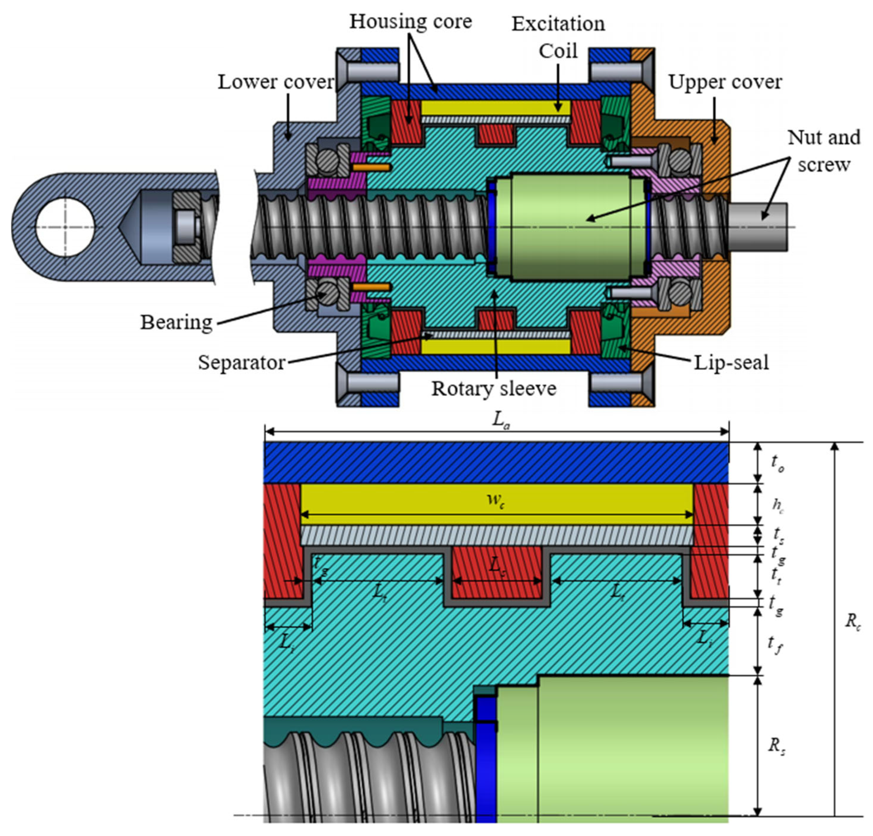
Figure 2.
FEM for magnetic analysis of SMRB damper.
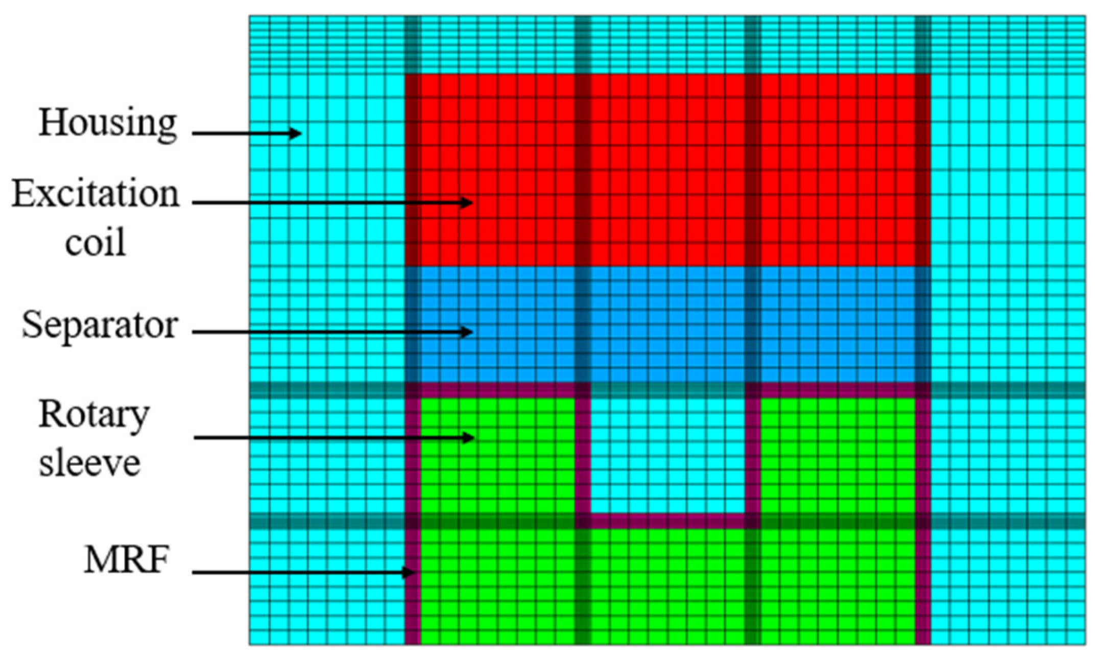
Figure 3.
FEM for magnetic circuit analysis of SMRB damper.
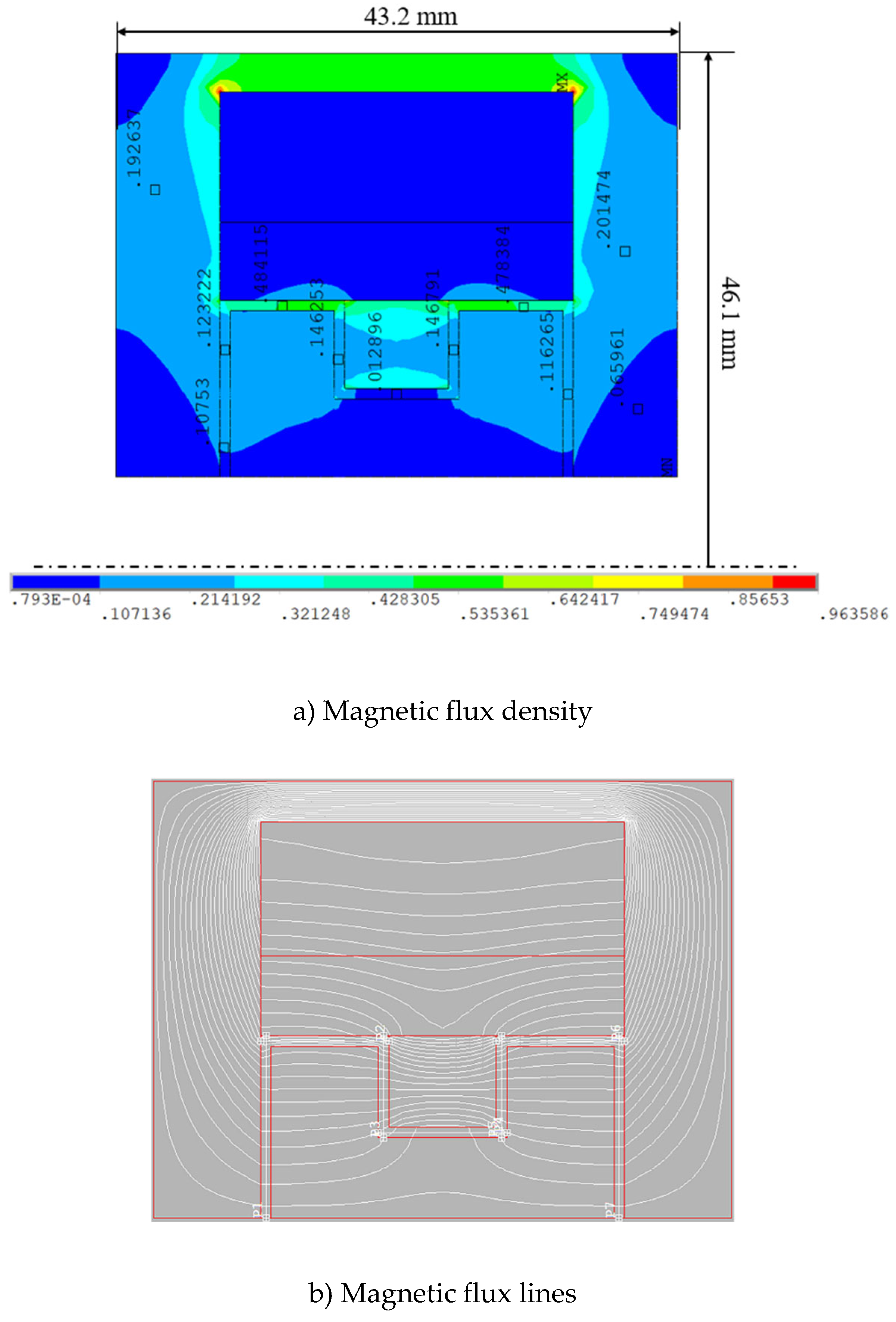
Figure 4.
Optimization solutions of the SMRB damper.
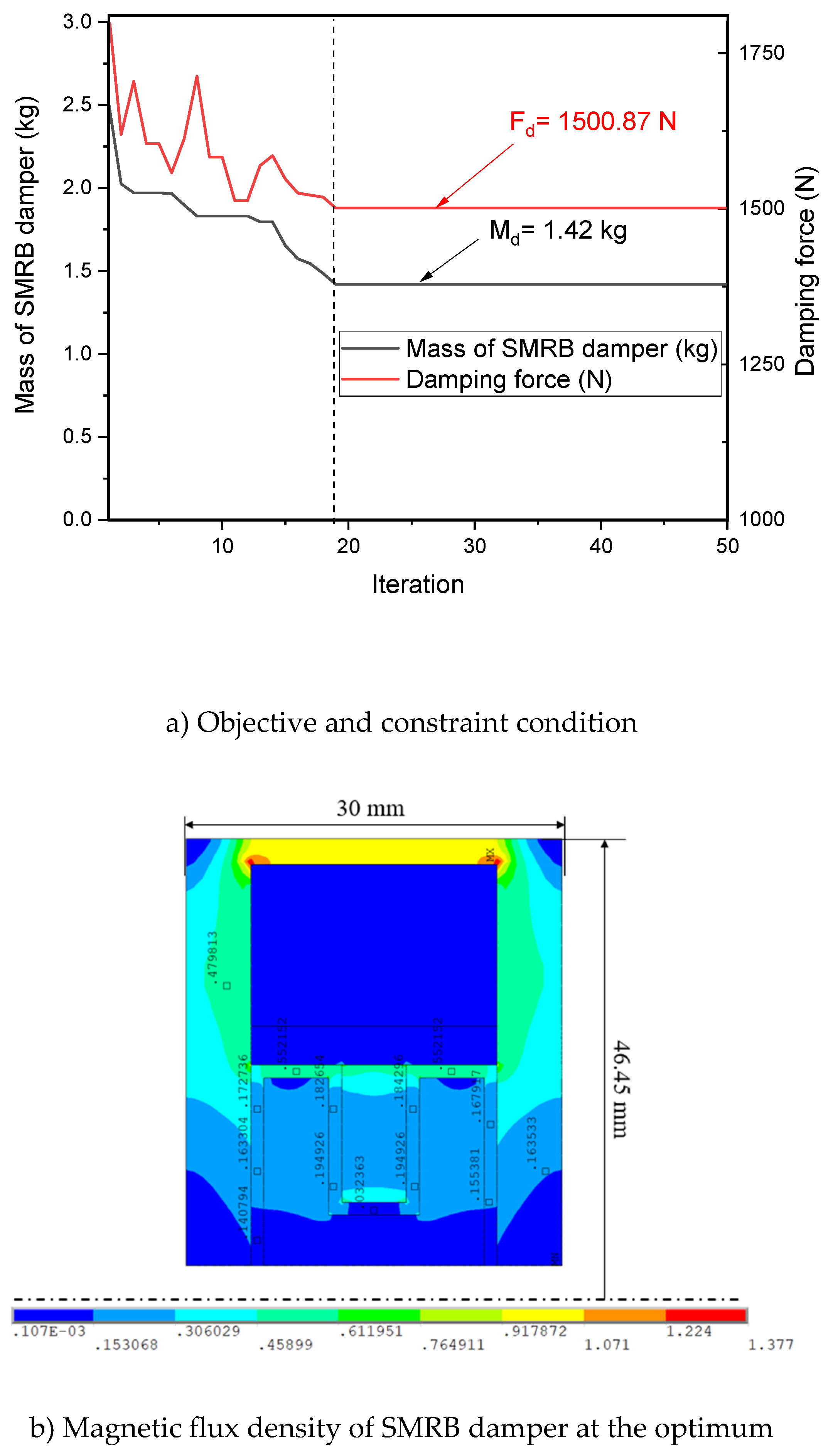
Figure 5.
The design model of SMRB damper.
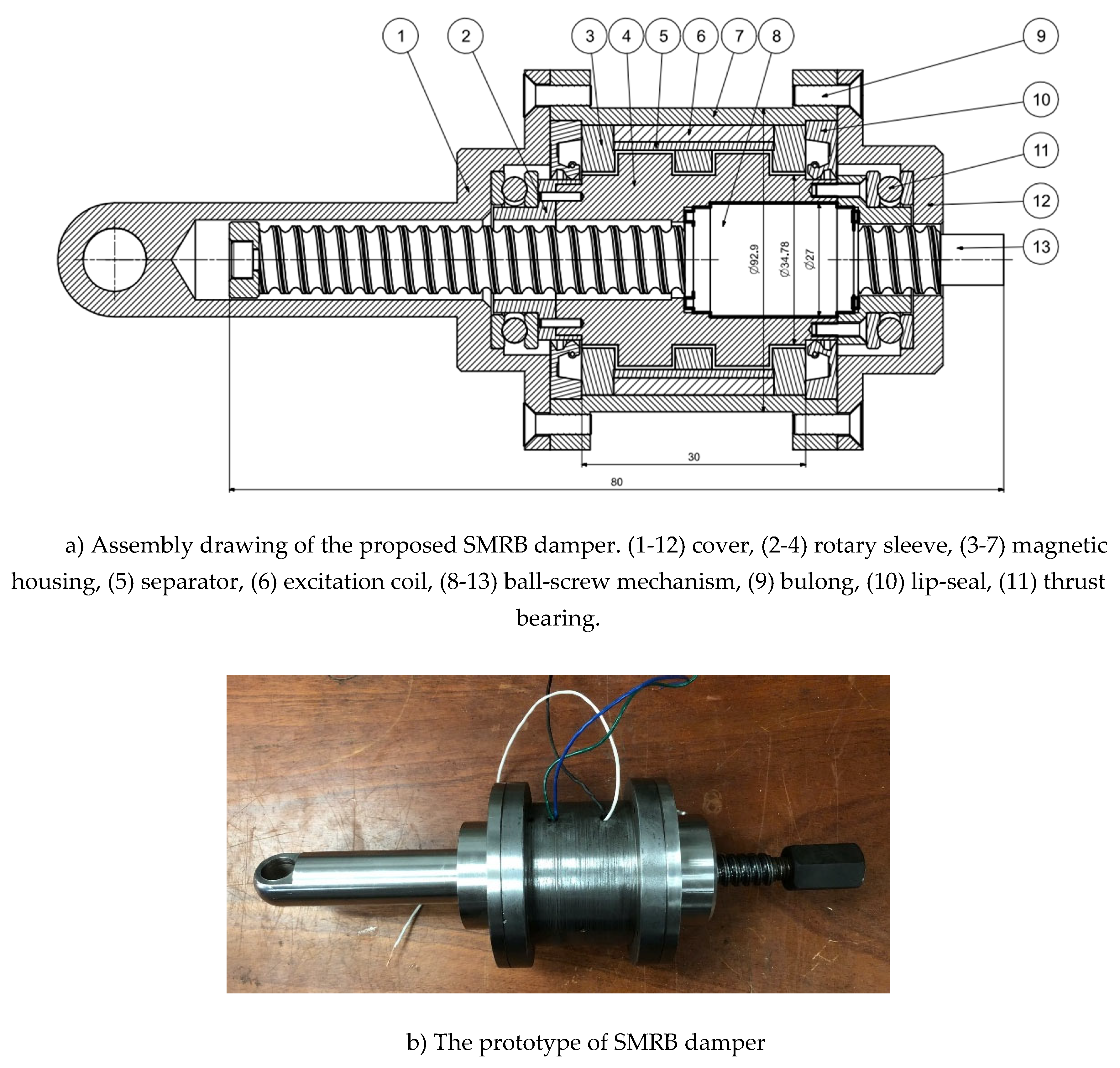
Figure 6.
The experimental test rig of the SMRB damper.
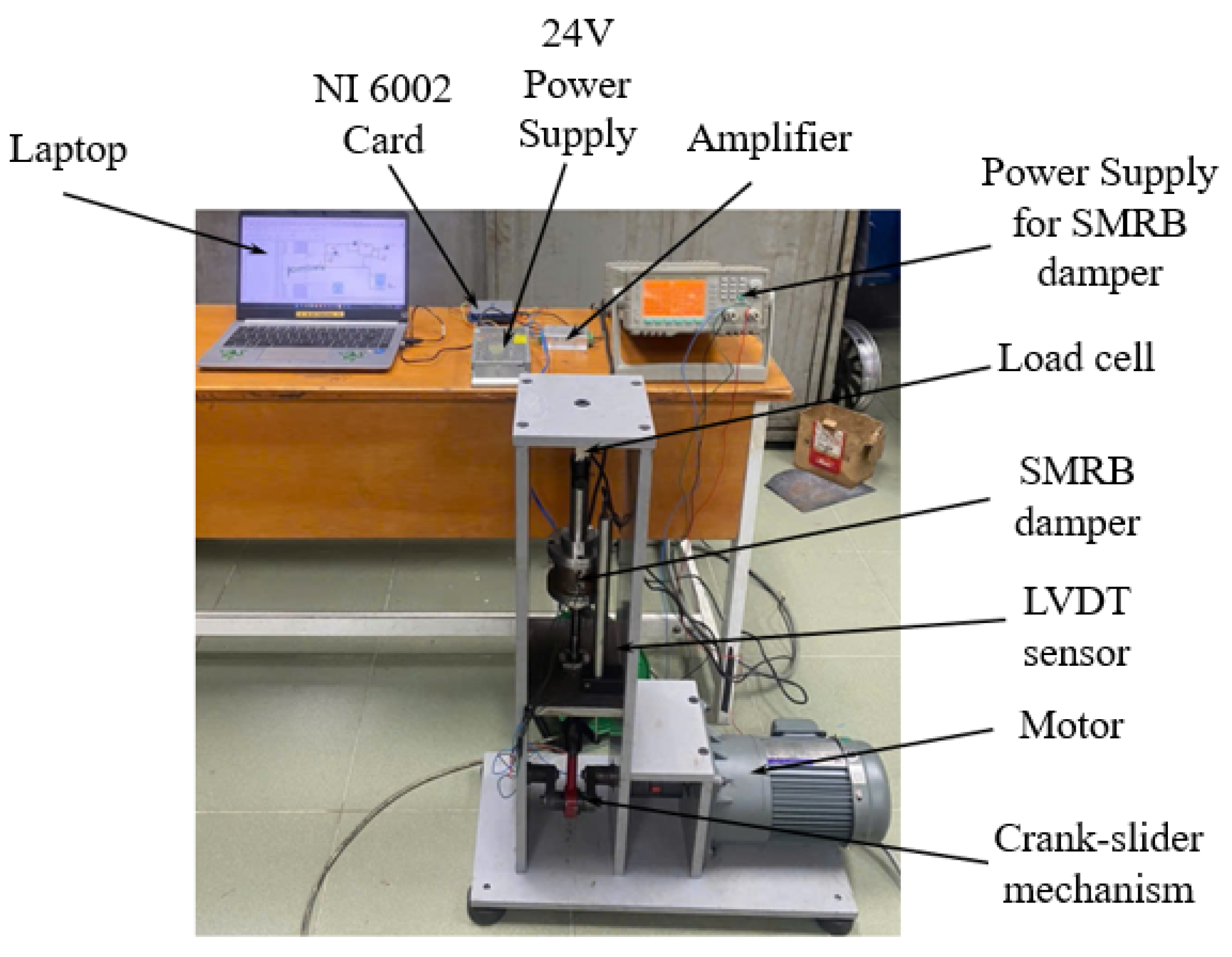
Figure 7.
Measured damping forces of the SMRB damper under different current levels at 0.5 Hz.
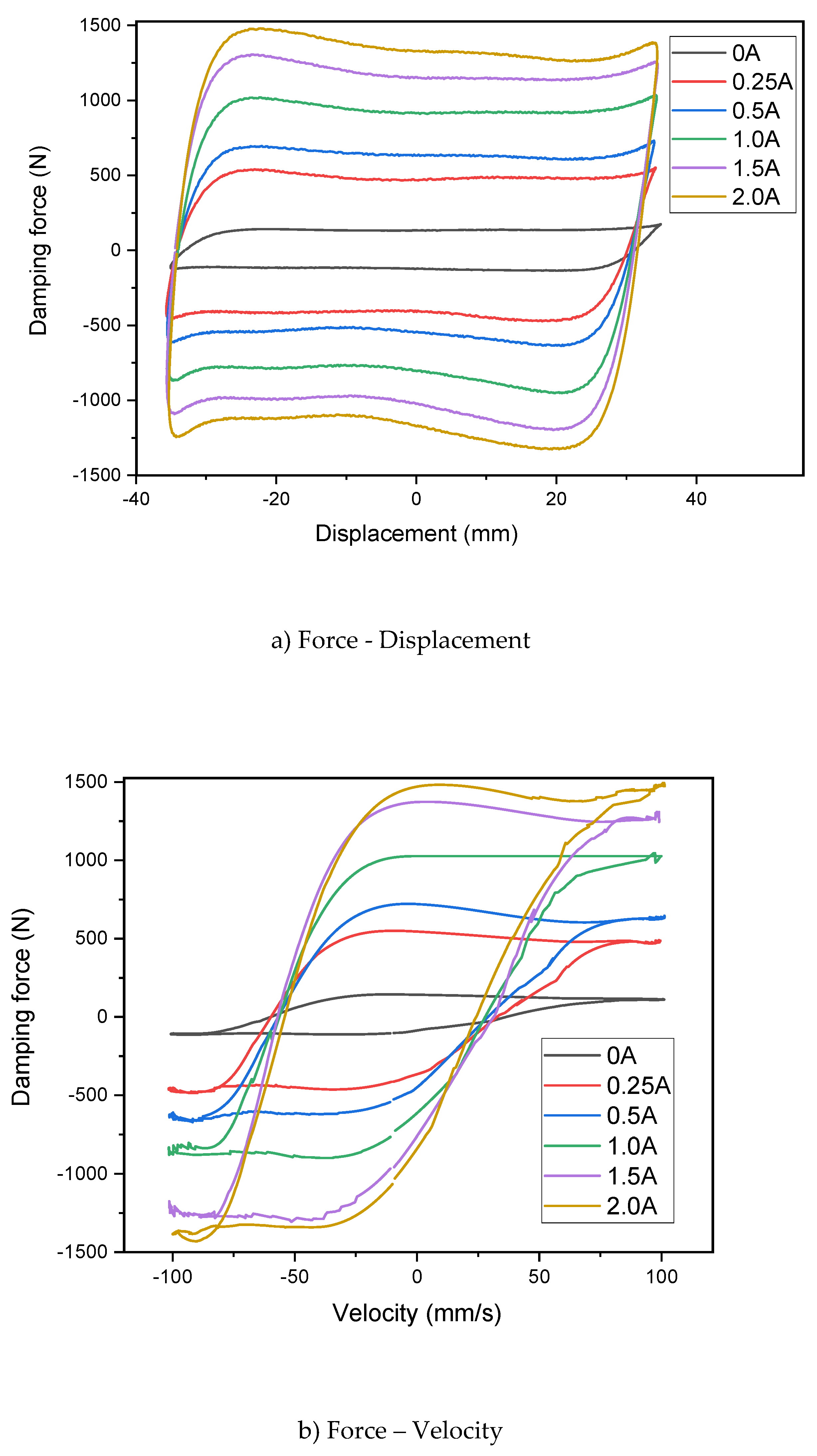
Figure 8.
Frequency-dependent damping performance of SMRB damper at fixed current (2.0A) and amplitude (37.5mm).
Figure 8.
Frequency-dependent damping performance of SMRB damper at fixed current (2.0A) and amplitude (37.5mm).
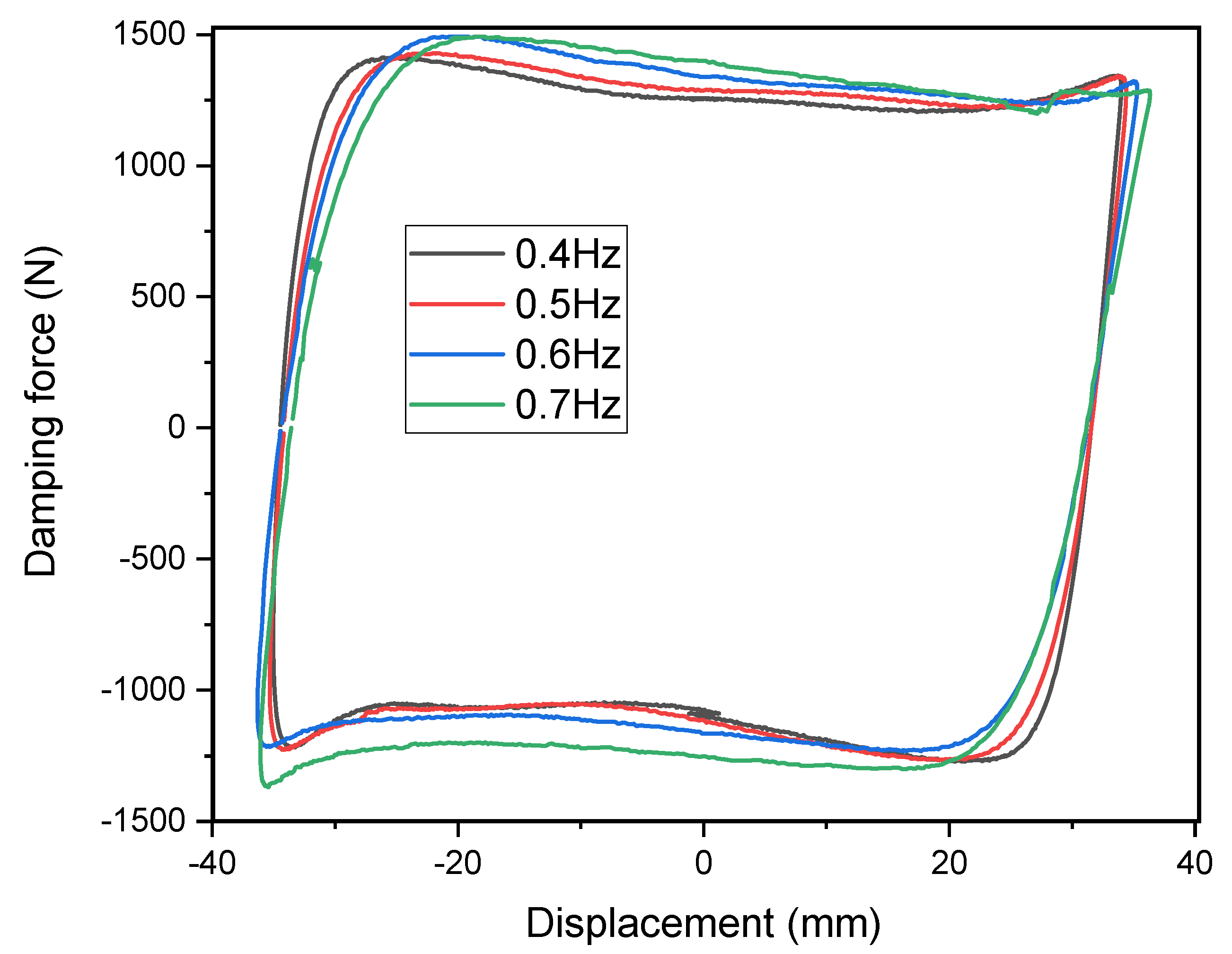

Table 1.
Optimal results of SMRB damper at the optimum.
| Types | Design parameter (mm) | Characteristics |
| SMRB damper |
Coil: Width of coil straight wcs = 19; Height of coil straight hcs = 12.5. Radius and length of magnetic core: Ra = 46.45 and La = 30; No. of turns: 613 turns. Rotary sleeve: tf = 3.89; Rotor tooth width and height: Lt = 5.2 and tt = 10.6. Middle stator tooth width: b = 5.2. Separator: ts = 3.0 Magnetic housing: Length: Li = Lo = 5.2; Thickness of housing: to = 2.0; MRF gap: tg = 1.0 |
Mass: 1.42 kg Damping force: 1500.87 N Off-state damping force: 104.51 N Power Consumption.: 64.57 W |
Disclaimer/Publisher’s Note: The statements, opinions and data contained in all publications are solely those of the individual author(s) and contributor(s) and not of MDPI and/or the editor(s). MDPI and/or the editor(s) disclaim responsibility for any injury to people or property resulting from any ideas, methods, instructions or products referred to in the content. |
© 2025 by the authors. Licensee MDPI, Basel, Switzerland. This article is an open access article distributed under the terms and conditions of the Creative Commons Attribution (CC BY) license (http://creativecommons.org/licenses/by/4.0/).
Copyright: This open access article is published under a Creative Commons CC BY 4.0 license, which permit the free download, distribution, and reuse, provided that the author and preprint are cited in any reuse.


