
Submitted:
14 December 2025
Posted:
16 December 2025
You are already at the latest version
Abstract
Microwave photonics has recently come to the forefront as a valuable approach to generating, processing, and measuring signals in high-performance domains such as communication, radar, and timing systems. Recent studies have introduced a range of photonics-based phase-noise analyzers (PNAs) that utilize a variety of architectures, including phase detection, frequency discrimination, and hybrid mechanisms that combine optical with electronic processing. This review delves into the microwave photonics methodologies developed with the specific purpose of measuring phase noise, by exploring their fundamental principles, system design frameworks, and performance indicators. Through the integration of insights garnered from recent publications, our objective is to deliver a comprehensive understanding of the strengths and limitations associated with PNAs and to pinpoint new and promising areas for advancing research in the field of oscillator metrology.
Keywords:
microwave photonics
; phase-noise measurement
; optical fiber
; delay-line method
; photonic processing
; sensitivity improvement
1. Introduction
The accurate characterization of phase noise in microwave oscillators is critical to developing high-performance communication systems [1], radar systems [2,3], quantum computing [4], experiments in big physics [5], and timing systems [6,7]. Phase noise has been a major constraint on the performance of modern electronic systems [8].
The development of microwave oscillators with low phase noise has long been a fundamental challenge when creating high-performance communication, radar, navigation, and timing systems. An important milestone was achieved with the introduction of the optoelectronic oscillator (OEO) by Yao and Maleki [9], who demonstrated the potential of using optical components to generate ultra-low-phase-noise microwave signals. This led to the development and rapid expansion of a new research field: microwave photonics.
In the past three decades, the rapid advances in optical fiber communications—driven by the need for high-speed, high-capacity data transmission—has led to the development of high-performance photonic components such as modulators, detectors, and integrated optical circuits [10,11]. Concurrently, progress in integrated optics has enabled compact, stable, and broadband photonic systems, while promoting the position of microwave photonics as a powerful tool for signal generation, processing, and measurement.
Microwave photonic techniques have also been increasingly adopted in metrology. Microwave photonics measurements have been used for spectrum analysis, instantaneous frequency measurements, microwave channelization, Doppler frequency-shift measurements, angle-of-arrival detection, and phase-noise measurements [12]. These techniques stand out for their broad bandwidths and speeds, which are not achievable with conventional electronic methods [13]. Particular interest has been shown in the accurate characterization of phase noise in oscillators. As a result, several photonic-enabled phase-noise analyzers with unprecedented sensitivity and bandwidth have been realized [14].
This review focuses on microwave photonics techniques that were specifically developed for phase-noise measurements. We examine their principles, system architectures, and performance. By synthesizing insights from our own investigations and the literature, we aim to provide an overview of microwave photonics-enabled phase-noise measurements, and to identify promising directions for future research in oscillator metrology.
2. Phase Noise and Its Characterization
Phase noise is the most important property of an oscillator and describes its short-term stability. It has been one of the main limitations of performance in the most advanced and high-end systems [8]. Therefore, it is no surprise that understanding the sources of phase noise and characterization techniques has been of great interest to researchers and industry for 60 years [15].
The signal of a non-ideal oscillator is
where is the amplitude, is the oscillation frequency, and is the random phase-fluctuation process [16,17]. Note that the signal of a real oscillator also includes the amplitude noise. However, effective countermeasures are known, and amplitude noise can be filtered out of the oscillator signal, which is not the case for phase noise. Therefore, amplitude noise is often neglected when studying the noise characteristics of oscillators.
Since phase noise is a random process, it is meaningful only to report its statistical properties. It is most practical to describe the phase noise using its power spectral density (PSD). For a stationary and ergodic random process, which phase noise is, it follows that
where is the Fourier transform of , and the units of are rad2/Hz.
IEEE Standard 1139 [18] defines the phase noise as
which is reported exclusively on a logarithmic scale as with units of dBc/Hz. The motivation behind the choice of units and the definition in (3) is backwards compatible with the now obsolete definition of phase noise as the power ratio [16,17].
2.1. Measurement Methods
Measuring the phase noise is one of the most demanding tasks for modern electrical engineers [19]. Conventional methods for measuring the phase noise are roughly divided into the direct method, the phase-detector method, the residual or interferometric method, the frequency-discriminator or delay-line method, and the cross-correlation method [17,20,21]. Apart from the direct method, which is the simplest but also the least accurate, all the other methods are related to the phase-detector method.
The phase-detector method, in its simplest form, consists of a mixer, a low-pass filter, and an FFT analyzer, as shown in Figure 1. The signal under test (SUT) is compared to the high-performance, low-noise reference signal. Given that the phase noise of the reference is negligible compared to the phase noise of the SUT, such that , and the inputs of the mixer are quadrature so that the mixer operates as a phase detector, then the output of the mixer is
where is the PSD of the voltage fluctuation at the mixer output, is the phase-to-voltage conversion factor of the mixer, and is the phase noise of the SUT. In practice, the requirement for quadrature on the mixer inputs dictates the use of a phased-locked loop on the reference. The need for a high-quality reference limits the usability of the method when measuring state-of-the-art low-noise sources. A solution using an optoelectronic oscillator as a high-quality reference was presented in [22].
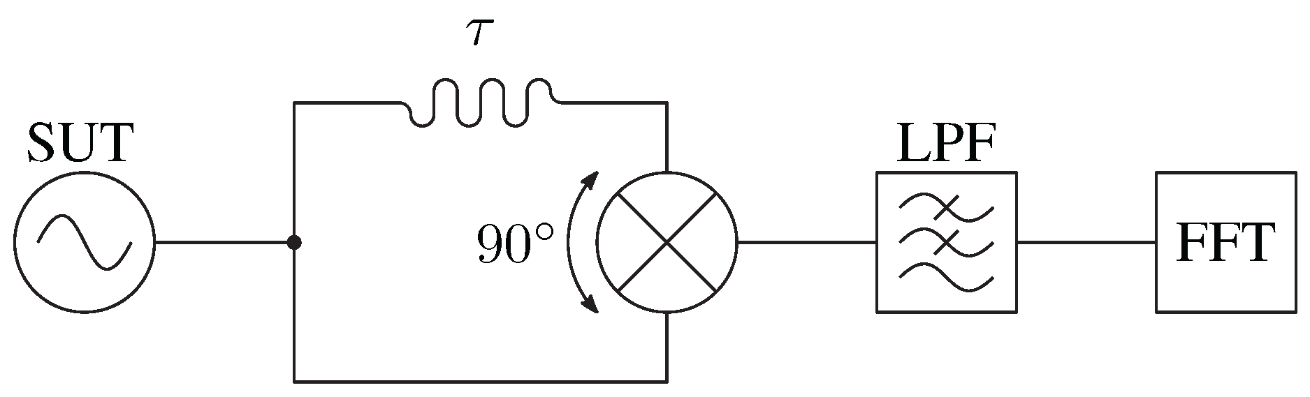
In the delay-line method, sometimes referred to as the frequency-discriminator method, the need for a high-performance, low-noise reference is removed. Instead, the SUT is divided into two paths, one of which includes a delay . The two paths are multiplied on the mixer, thus a SUT is compared with its delayed self rather than with a reference signal. The delay introduces zeros in the transfer function
which limits the useful noise bandwidth of the measurement and dictates the choice of delay. As with the phase-detector method, here too, the quadrature condition is required at the mixer inputs; therefore, in practice, some phase adjustment is required in either the delayed or non-delayed arm of the measurement setup. In practice, a delay of the order of 1 to 10 gives the best balance between sensitivity and noise bandwidth. Historically, implementing a suitable delay posed an obstacle that made the method unattractive. However, it has seen attempts at a commercial solution [23].
Figure 2.
Delay-line or frequency-discriminator method. The SUT is split into two paths, one of which is considerably longer. The mixer operates as a phase detector. SUT: signal under test, LPF: low-pass filter, FFT: fast-Fourier-transform analyzer.
Figure 2.
Delay-line or frequency-discriminator method. The SUT is split into two paths, one of which is considerably longer. The mixer operates as a phase detector. SUT: signal under test, LPF: low-pass filter, FFT: fast-Fourier-transform analyzer.
The cross-correlation method became the norm in phase-noise metrology due to its high sensitivity [24]. Therefore, it is the basis for commercial instruments such as Keysight E505xA Signal Source Analyzers and Rohde&Schwarz FSWP Phase Noise Analyzers. The sensitivity of the phase-detector method is limited by the phase noise of the reference and the additive phase noise of other components in the measurement setup. This limitation can be circumvented by taking two independent measurements simultaneously. The price is doubling the setup, including the reference. The two measurements are then cross-correlated. The measurement taken is
where m is the number of cross-correlations. Since the two measurement channels are independent, the contributions of each reference and the corresponding components can be arbitrarily made by simply taking more measurements. Figure 3 shows the cross-correlation method.
The residual or interferometric method is used to measure the phase noise of two-port devices such as amplifiers, frequency multipliers, etc. Its topology closely resembles the delay-line method, but the delay is replaced by the device under test (DUT), as shown in Figure 4.
If the lengths of the reference path and the path through the DUT are delay-matched, the noise from the reference oscillator is suppressed, and only the phase-noise contribution from the DUT is seen at the output of the mixer. For further details, the reader is referred to [25,26,27,28].
The development of high-speed digital electronics led to the direct digital implementation of the phase detector and cross-correlation method, which exhibits an ultra-low noise floor but is limited by the analog-to-digital conversion bandwidth [29,30,31,32,33,34]. Recently, phase-noise measurements based on the Bayesian filtering framework and machine-learning techniques have been demonstrated [35] with the phase-detector topology and [36,37] with the delay-line topology.
3. Fiber-Optic Delay-Line Method
Optical fiber, with its ultra-low loss (0.2 dB/km) and extremely wide bandwidth (tens of THz), enables unprecedented delays. It is no surprise that among the conventional methods, the delay-line method is the main subject of microwave photonics. In its simplest form, the photonic delay is implemented as an analog fiber optic link using intensity modulation and direct detection (IM/DD). This gives a delay
where L is the length of the optical fiber, n is the refractive index of the optical fiber, and c is the speed of light in vacuum. Tens of kilometers of fiber can be used without the need for optical amplification, making delays of hundreds of microseconds achievable. When the optoelectronic oscillator (OEO) was presented in 1996 [9], it used such a fiber-optic delay in the feedback loop of the oscillator, which spawned a whole new field of research [38,39,40] and as fiber-optic delay to evaluate the phase noise of the presented OEO. However, it took another 10 years for the first in-depth treatment by Rubiola et al. [41,42]. Figure 5 shows a simple implementation of the delay-line phase-noise measurement method, in which the delay is implemented as an IM/DD analog optical link with a Mach-Zehnder modulator, and quadrature is ensured with an additional variable phase shifter.
Together with the Mach-Zehnder modulator, a delay realized with the electro-absorption modulator (EAM) [43] and direct modulation of the laser current [44] have been demonstrated to provide performance comparable to the MZM with reduced complexity and cost. Compared to EAM and direct modulation, the MZM solution requires the careful selection of modulation bias voltage, polarization of the incident light, and stabilization of the environment. On the other hand, a more complex MZM configuration allows a sophisticated manipulation of the optical modulated signals. Figure 6a shows the example of a dual-parallel MZM (DP-MZM), and Figure 6b shows a dual-polarization MZM (DPol-MZM), which enables the independent modulation of two orthogonal polarization planes.
In [45], external low-frequency phase modulation of the SUT prior to injection into the fiber-optic delay-line phase-noise meter enables automatic calibration during measurement, making the phase-noise meter suitable for use outside laboratory environments.
The impact of the optical fiber itself on the phase noise was extensively studied in [46,47,48]. An in-depth investigation of the phase-noise contribution from individual elements of the IM/DD optical link was presented in [49]. The study presents the impact of fiber-related properties such as double Rayleigh scattering, chromatic dispersion, and fiber length, as well as the properties of other components such as laser relative-intensity noise, power, and linewidth.
Based on the simple implementation shown in Figure 5, the research went in two directions: setting and maintaining the quadrature condition for correct operation, and improving the sensitivity. Both directions have in common the graduated move of functionalities from the microwave to the optical domain.
3.1. Photonic Processing
Microwave photonics has emerged as a field in which photonics are exploited for processing microwave signals. For the correct operation of the down-converting phase noise to the baseband, a quadrature condition needs to be satisfied on the down-converting component. This requires some method of signal phase manipulation in the measurement setup. While simple solutions [41,43,44] use a mechanical microwave phase shifter that requires manual adjustment, Zhu et al. [50] used a photonic processor based on a microwave photonic phase shifter implemented with a single-sided polarization modulator and polarizer, as shown in Figure 7.
By carefully selecting the bias voltage of the polarization modulator, the phase between the signals in the two main polarization planes can be carefully selected. The polarization controller (PC) together with the polarizer acts as a selective detector. The microwave photonics subsystem now provides both the required delay and phase shift. However, the use of polarization modulation makes the system very sensitive to environmental disturbances. This is addressed by the use of a dual-parallel MZM and optical band-pass filter (OBPF) in [51]. By carefully selecting the three bias voltages of the dual-parallel MZM, the phase between the modulation sidebands and the optical carrier can be continuously selected. The setup is shown in Figure 8.
The OBPF ensures single-sideband detection at the photodiode. Another way of achieving the required phase shift was presented in [52]. This approach uses photonic-assisted frequency up- and down-conversion. The proposed solution requires a local oscillator that provides frequency up-conversion together with a dual-drive MZM and OBPF.
The required quadrature condition at the mixer inputs can also be achieved via precise delay tuning. The authors presented a solution that exploits the otherwise undesirable effect of chromatic dispersion to fine tune the delay of the modulated signal. Chromatic dispersion is the result of frequency dependence of the refractive index of the optical fiber. The propagation delay of the signal can be written as
where is the non-dispersive delay and is the group delay caused by the chromatic dispersion. For small changes in the wavelength , the change in group delay can be approximated as
where L is the fiber length and D is the average chromatic dispersion coefficient over . It follows from equations (8) and (9) that by changing the laser’s wavelength, the delay can be accurately tuned. The tuning of the delay for according to equation (9) translates into the available phase change of the signal
This can be easily achieved with standard telecom components using the temperature control of the laser diode for wavelength tuning [53]. Such a realization is robust and economical because its reuse of mass-produced telecom components and slow electronics for temperature control. Standard G.652 fiber has a relatively low chromatic dispersion coefficient, typically // in the C-band wavelengths, which limits delay tunability to approximately 140 ps. With equation (10) in mind, a full 360 phase shift is available for SUT in the X-band and above. Techniques to increase delay tunability were further investigated.
Due to chromatic dispersion, the carrier and sidebands accumulate different phases along the fiber, resulting in pulse spreading and power fading [54]. To combat this effect in optical communication networks, special dispersion-compensating fiber (DCF) is used [55,56,57]. DCF has a high chromatic dispersion coefficient with the opposite sign to standard telecom fiber. Using DCF greatly increases the delay tunability for the same fiber length and wavelength tuning of the laser. A phase-noise measurement using DCF was presented in [58]. These solutions maintain simplicity by changing only the type of fiber, while improving the operating bandwidth of the setup. However, DCFs are available in modules optimized to compensate for a specific length of standard optical fiber, which limits the flexibility of their use in other applications. To overcome this limitation, a dual-fiber solution is proposed in [59] and shown in Figure 9.
What distinguishes this solution from the setup in [41] is that the fibers used in each branch have different chromatic dispersion coefficients. In this way, the delay tuning is given by
where and are the chromatic dispersion coefficients and fiber lengths, respectively. The available tuning range can be extended by using longer fibers, as long as the difference between the two paths satisfies the required delay given by equation (7).
The above solutions used photonics techniques to ensure the quadrature condition for the correct operating regime of the microwave mixer. Another solution, shown in Figure 10 and presented in [60], uses a photodiode in place of the mixer, thus implementing a photonic down-converter.
This is realized by using two electro-optic modulators and an OBPF to filter out only one pair of sidebands. On the photodiode, the pair of sidebands is converted directly to the baseband of the noise. The phase shifter sets the correct phase between the sidebands. The use of a photonic phase shifter and a photonic delay was merged, as shown in Figure 11 and was first presented in [61].
The second modulator is replaced by the polarization modulator, and an additional polarizer is inserted in front of the photodiode. This was further improved in [62], where the polarization modulator is replaced by a dual polarization MZM, thus reducing the cost and improving the bandwidth of the measurement setup.
The need for phase manipulation in either branch of the delay-line measurement can be avoided by using the quadrature mixer with digital phase demodulation, as presented in [63]. The implementation with photonic delay, described in [64] and shown in Figure 12, follows this approach.
The mixer that serves as the phase detector is replaced by a quadrature mixer realized with discrete, off-the-shelf connectorized modules. The baseband now requires two analog-to-digital converters (ADCs) to sample both the in-phase (I) and quadrature (Q) components of the down-converted signal. The phase noise is then extracted with digital post-processing
Additionally, the setup in [64] introduces a fiber piezo-stretcher, which allows slow delay modulation by stretching the fiber length. The small but known fluctuation in time delay is converted to the known phase fluctuation of a down-converted signal, enabling automatic calibration of the measurement setup and compensation of the quadrature mixer’s imperfections.
Following the trend of shifting functionalities to the optical domain, a solution with photonic-assisted I/Q mixing was presented in [65], where a photonic I/Q mixer is used instead of a microwave mixer. The photonic I/Q mixer is implemented by driving a dual-polarization MZM from a 90 hybrid. Each modulation sideband consists of an in-phase and quadrature component, which are now polarization-coded. Using an OBPF, only one sideband is selected, and then one sideband is split via a polarization beam splitter (PBS), thus separating the components to two individual photodiodes. The output of the photodiodes includes the corresponding in-phase or quadrature signal and a DC offset, which needs to be measured in advance and corrected during post-processing. Figure 13 shows the described measurement setup based on a photonic-assisted I/Q mixer.
The use of an electrical 90 hybrid limits the microwave bandwidth of the proposed setup. This limitation was successfully addressed in [66], where the dual-polarization MZM is replaced by a polarization modulator, as in [50]. In the same manner as in [64], the variable optical delay line enables the automatic calibration and correction of the quadrature relation between the two polarizations by changing the PolM bias voltage. Figure 14 shows an all-optical I/Q mixer measurement. The use of a PolM relaxes the microwave bandwidth constraints but is sensitive to environmental changes.
3.2. Sensitivity Improvements
Another challenge addressed in the literature is the sensitivity of the phase-noise measurement setup. Assuming the system is operating correctly, the question is how low the measured phase noise can be while still being distinguishable from the noise of the measuring device. Hong and Yin showed in [67] that the careful selection of components can greatly improve the sensitivity of a simple, single delay-line measurement setup.
The industry and research standard with conventional phase-noise measurements is the use of cross-correlation. This can be easily implemented by duplicating the setup and performing a cross-correlation over simultaneous measurements. The successful adoption of the cross-correlation technique with the photonic delay method was presented in [68,69,70,71,72,73] and is shown in Figure 15. The same fiber was reused in both channels using wavelength division multiplexing in [74]. Two variable optical delay lines are used for each channel to ensure a quadrature condition on the corresponding mixers.
The uncertainty of the photonic-delay cross-correlation method has been rigorously examined [75,76].
Another technique to increase sensitivity was adopted in [77], where an electro-optic frequency comb is used to amplify the measured phase noise. The DUT drives an electro-optical frequency comb, where the phase noise of the DUT is transferred to the higher-order modes of the comb
where is the order of the comb mode. The phase-noise contribution from the DUT rises linearly with the order of the comb mode, while the contribution of the measurement setup, mainly the laser noise, is constant. Since selecting the higher-order modes of the comb is effectively a frequency multiplication, n-times-faster electronics are implied. However, [77] proposes the self-heterodyne method, also used for characterizing mode-locked lasers [78,79]. The comb on the non-delayed path is frequency shifted by with the acusto-optic modulator (AOM). After the delay and frequency shift, two OBPF selects a pair of modes. The required bandwidth of the photodiodes and electronics is then determined by , which is in the range of 100 MHz. The proposed solution is shown in Figure 16.
The technique was further developed in [80], where heterodyning with an AOM was replaced by an I/Q detector based on optical hybrids. In addition to two optical 90 hybrids, four balanced photodiodes (BPDs) are used, which are free of DC voltage on detection. Apart from the DC absence on the detection, BPDs also suppress the DUT amplitude noise and the contribution of the laser noise, which also contributes to an enhanced measurement sensitivity. The complete setup is shown in Figure 17. Although such a complete system exhibits impressive bandwidth and sensitivity, it requires application-specific components such as optical 90 hybrids and reconfigurable optical bandpass filters, making the system costly and inaccessible outside specialized laboratory environments.
The laser and the amplifiers are the main contributors to the noise floor of the measurement setup. The delay-line method inherently uses the topology of an interferometer, so it is no surprise that advanced techniques of the interferometric or residual method to measure the phase noise [26] have also been adopted for the delay-line method. Rubiola et al. presented in [81] a detection scheme in which the carrier is suppressed in one arm of the setup. The scheme, shown in Figure 18, takes advantage of the fact that there is no up-conversion of the 1/f noise in the absence of a strong carrier signal [27].
This allows a gain of 40 dB without polluting the signal with the amplifier’s own noise [25]. The described carrier-suppression technique has been successfully applied to the photonic-delay method in [82] where the carrier-suppression scheme of Figure 18 follows the photodiodes. Using this technique, the laser-noise contribution was suppressed by approximately 60 dB, and the noise floor was improved compared to commercial instruments.
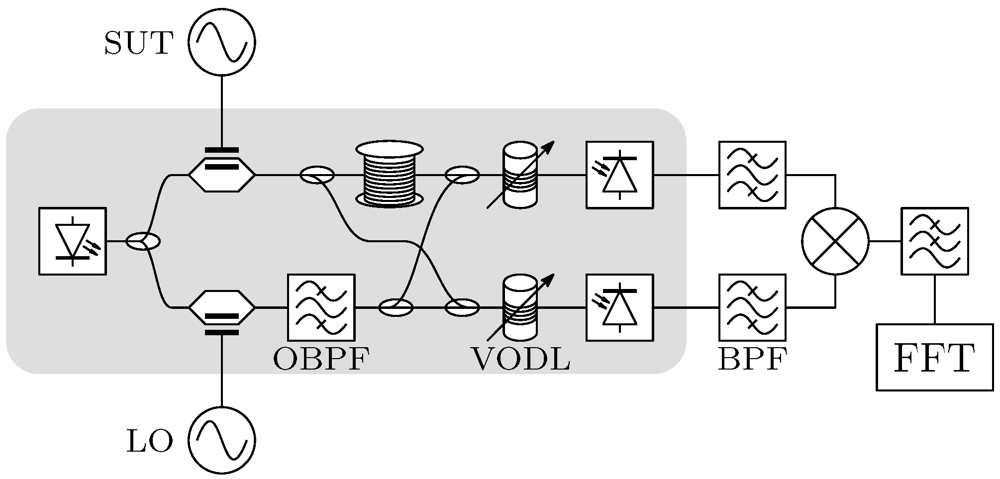
An attempt to improve the sensitivity of the coaxial-cable-based delay-line method was presented in [83], where a SUT is converted down to the intermediate frequency, resulting in lower attenuation for the coaxial cable delay. This idea was further developed in [84], where the delay is implemented using photonics. With optical fiber, the delay loss is no longer an issue. Translating the frequency to the intermediate frequency also benefits the requirements for photodiodes and microwave electronics. The proposed solution is shown in Figure 19.
The optical carrier is divided into two paths. One is modulated by the SUT, and the other is modulated by a local oscillator (LO) for frequency translation. In the LO path, a single modulation sideband is passed through the OBPF to the two photodiodes, while the SUT is further split into delayed and non-delayed paths. in addition to the optical-electrical conversion, the role of photodiodes is also frequency translation to the intermediate frequency
While the SUT path follows the delay-line or frequency-discriminator method in which a longer mismatch between two arms translates to better sensitivity, the LO path follows the residual or interferometric method in which the two arms have to be equal to suppress the noise of the reference oscillator, in this case the LO. To achieve this, two variable optical delay lines are inserted before the photodiodes. The requirements in terms of LO quality are loosened due to the noise suppression.
4. Conclusion
This review provides an organized overview of microwave photonic techniques for phase-noise measurements in microwave signal sources. We examined the development and progress in phase-noise measurements using microwave photonic techniques. The primary focus of the field is the delay-line method, which became attractive because optical fiber allows adequate photonic delays. The fiber-optic delay-line method forms the foundation of most approaches, benefiting from the exceptionally low loss and wide bandwidth of optical fiber. The earliest microwave photonic implementations of phase-noise measurements simply replaced the delay element with an analog optical link. More advanced and complex microwave photonic techniques have transferred processing functionalities to the optical domain, enabling all-optical phase-noise meters that outperform commercially available instruments. Regardless of the success, the photonic delay-line phase-noise measurement method continues to be an attractive research topic. It has been used successfully for the emulation and characterization of phase-noise impact on frequency-modulated continuous wave radar [85]. The photonic delay has also been used to reduce the phase noise of noisy voltage-controlled oscillators [86].
Looking ahead, integrating photonic delay, modulation, and mixing functions on chip-scale platforms is expected to greatly reduce the cost, footprint, and environmental sensitivity.
In summary, microwave photonic phase-noise measurements have matured into a versatile and powerful framework that now surpasses many state-of-the-art electronic solutions in sensitivity and bandwidth. Continued development toward compact, stable, and self-calibrating photonic architectures will be the key to enabling next-generation high-performance communication, radar, and time-frequency systems.
Author Contributions
Conceptualization, A.L. and M.V.; investigation, A.L.; writing—original draft preparation, A.L.; writing—review and editing, A.L., M.V. and B.B.; visualization, A.L.; project administration, B.B.; funding acquisition, B.B. All authors have read and agreed to the published version of the manuscript.
Institutional Review Board Statement
Not applicable.
Informed Consent Statement
Not applicable.
Data Availability Statement
Data sharing is not applicable.
Conflicts of Interest
The authors declare no conflicts of interest.
References
- Hilt, A. Throughput Estimation of K-zone Gbps Radio Links Operating in the E-band. In Informacije MIDEM - Journal of Microelectronics, Electronic Components and Materials; Drustvo MIDEM, 2022; Volume 52. [Google Scholar] [CrossRef]
- Leeson, D.B.; Johnson, G.F. Short-term stability for a Doppler radar: Requirements, measurements, and techniques. In Proceedings of the IEEE; Publisher; Institute of Electrical and Electronics Engineers (IEEE), 1966; Volume 54, pp. 244–248. [Google Scholar] [CrossRef]
- Podbregar, L.; Batagelj, B.; Blatnik, A.; Lavrič, A. Advances in and Applications of Microwave Photonics in Radar Systems: A Review. Photonics 2025, 12, 529. [Google Scholar] [CrossRef]
- Chang, H.Y.; Chen, P.Y.; Chen, A.Y.K. Low-Phase-Noise and Low-Jitter Signal Generation Techniques for 5G/6G and Quantum Computing Applications. IEEE Microwave Magazine 2025, 26, 76–98. [Google Scholar] [CrossRef]
- Yu, T.; Xue, K.; Long, H.; Wang, Z.; Liu, Y. Simulation of Heterodyne Signal for Science Interferometers of Space-Borne Gravitational Wave Detector and Evaluation of Phase Measurement Noise. Photonics 2025, 12. [Google Scholar] [CrossRef]
- Tratnik, J.; Lemut, P.; Vidmar, M. Time-transfer and synchronization equipment for high-performance particle accelerators. Informacije MIDEM - Journal of Microelectronics, Electronic Components and Materials 2012, 42, 115–122. [Google Scholar]
- Wang, J.; Su, X.; Yu, J.; Luo, H.; Gao, Y.; Han, X.; Huang, C. A Distributed Microwave Signal Transmission System for Arbitrary Multi-Node Download. Photonics 2025, 12. [Google Scholar] [CrossRef]
- Vidmar, M. Extending Leeson’s Equation. In Informacije MIDEM - Journal of Microelectronics, Electronic Components and Materials; Drustvo MIDEM, 2021; Volume 51, pp. 135–146. [Google Scholar] [CrossRef]
- Yao, X.S.; Maleki, L. Optoelectronic microwave oscillator. In Journal of the Optical Society of America B; Optica Publishing Group, 1996; Volume 13, p. 1725. [Google Scholar] [CrossRef]
- Vidmar, M. Optical-fiber Communications: Components and Systems. Informacije MIDEM - Journal of Microelectronics, Electronic Components and Materials 2001, 31, 246–251. [Google Scholar]
- Batagelj, B.; Pavlovič, L.; Naglič, L.; Tomažič, S. Convergence of fixed and mobile networks by radio over fibre technology. Informacije MIDEM - Journal of Microelectronics, Electronic Components and Materials 2011, 41, 144–149. [Google Scholar]
- Zou, X.; Lu, B.; Pan, W.; Yan, L.; Stöhr, A.; Yao, J. Photonics for microwave measurements. In Laser & Photonics Reviews; Wiley, 2016; Volume 10, pp. 711–734. [Google Scholar] [CrossRef]
- Pan, S.; Yao, J. Photonics-Based Broadband Microwave Measurement. In Journal of Lightwave Technology; Institute of Electrical and Electronics Engineers (IEEE), 2017; Volume 35, pp. 3498–3513. [Google Scholar] [CrossRef]
- Shi, J.; Tu, B.; Wang, Y. Photonics-Enabled High-Sensitivity and Wide-Bandwidth Microwave Phase Noise Analyzers. In Photonics; MDPI AG, 2025; Volume 12. [Google Scholar] [CrossRef]
- Leeson, D.B. Oscillator Phase Noise: A 50-Year Review. IEEE Transactions on Ultrasonics, Ferroelectrics, and Frequency Control 2016, 63, 1208–1225. [Google Scholar] [CrossRef]
- Rubiola, E. Phase noise and frequency stability in oscillators; The Cambridge RF and microwave engineering series; Cambridge University Press: Cambridge, 2011. [Google Scholar] [CrossRef]
- Rubiola, E.; Vernotte, F. The Companion of Enrico’s Chart for Phase Noise and Two-Sample Variances. In IEEE Transactions on Microwave Theory and Techniques; Institute of Electrical and Electronics Engineers (IEEE), 2023; Volume 71, pp. 2996–3025. [Google Scholar] [CrossRef]
- 1139-2022 - IEEE Standard Definitions of Physical Quantities for Fundamental Frequency and Time Metrology–Random Instabilities - Redline. IEEE, 2022. [PubMed Central]
- Rohde, U.L.; Poddar, A.K.; Apte, A.M. Getting Its Measure: Oscillator Phase Noise Measurement Techniques and Limitations. In IEEE Microwave Magazine; Institute of Electrical and Electronics Engineers (IEEE), 2013; Volume 14, pp. 73–86. [Google Scholar] [CrossRef]
- Barnes, J.A.; Chi, A.R.; Cutler, L.S.; Healey, D.J.; Leeson, D.B.; McGunigal, T.E.; Mullen, J.A.; Smith, W.L.; Sydnor, R.L.; Vessot, R.F.C.; et al. Characterization of Frequency Stability. In IEEE Transactions on Instrumentation and Measurement; Institute of Electrical and Electronics Engineers (IEEE), 1971; Volume IM-20, pp. 105–120. [Google Scholar] [CrossRef]
- Lance, A.L.; Seal, W.D.; Labaar, F. Phase noise and AM noise measurements in the frequency domain. Infrared and Millimeter Waves 1984, 11, 239–289. [Google Scholar]
- Peng, H.; Xu, Y.; Guo, R.; Du, H.; Chen, J.; Chen, Z. High sensitivity microwave phase noise analyzer based on a phase locked optoelectronic oscillator. In Optics Express; Optica Publishing Group, 2019; Volume 27, p. 18910. [Google Scholar] [CrossRef]
- Phase Noise Characterization: Frequency Discriminator Method: Product Note 11729C-2. 1985.
- Rubiola, E.; Vernotte, F. The cross-spectrum experimental method. 2010, 1. [Google Scholar] [CrossRef]
- Rubiola, E.; Giordano, V.; Groslambert, J. Very high frequency and microwave interferometric phase and amplitude noise measurements. Review of Scientific Instruments 1999, 70, 220–225. [Google Scholar] [CrossRef]
- Rubiola, E.; Giordano, V. Advanced interferometric phase and amplitude noise measurements. Review of Scientific Instruments 2002, 73, 2445–2457. [Google Scholar] [CrossRef]
- Boudot, R.; Rubiola, E. Phase noise in RF and microwave amplifiers. IEEE Transactions on Ultrasonics, Ferroelectrics and Frequency Control 2012, 59, 2613–2624. [Google Scholar] [CrossRef]
- Teyssieux, D.; Callejo, M.; Millo, J.; Rubiola, E.; Boudot, R. Phase noise measurement of optical amplifiers. Journal of Lightwave Technology 2025, 1–6. [Google Scholar] [CrossRef]
- Angrisani, L.; D’Apuzzo, M.; D’Arco, M. A digital signal-processing approach for phase noise measurement. IEEE Transactions on Instrumentation and Measurement 2001, 50, 930–935. [Google Scholar] [CrossRef]
- Angrisani, L.; Schiano Lo Moriello, R.; D’Arco, M.; Greenhall, C. A Digital Signal Processing Instrument for Real-Time Phase Noise Measurement. IEEE Transactions on Instrumentation and Measurement 2008, 57, 2098–2107. [Google Scholar] [CrossRef]
- Fleischmann, P.; Mathis, H.; Kucera, J.; Dahinden, S. Implementation of a Cross-Spectrum FFT Analyzer for a Phase-Noise Test System in a Low-Cost FPGA. International Journal of Microwave Science and Technology 2015, 2015, 1–7. [Google Scholar] [CrossRef]
- De Visme, P.; Imbaud, J.; Holme, A.; Sthal, F. Comparison of an Affordable Open-Source Phase Noise Analyzer With Its Commercial Counterpart. IEEE Transactions on Instrumentation and Measurement 2024, 73, 1–7. [Google Scholar] [CrossRef]
- Pomponio, M.; Hati, A.; Nelson, C. Direct Digital Simultaneous Phase-Amplitude Noise and Allan Deviation Measurement System. IEEE Open Journal of Ultrasonics, Ferroelectrics, and Frequency Control 2024, 4, 160–170. [Google Scholar] [CrossRef]
- Bu, F.; Zhao, Z.; Li, L.; Zhang, C.; Li, T.; Qi, Y.; Ding, J.; Yan, B.; Zhao, C.; Wang, Y.; et al. Laser Linewidth Measurement Using an FPGA-Based Delay Self-Homodyne System. Photonics 2025, 12. [Google Scholar] [CrossRef]
- Zibar, D.; Chin, H.M.; Tong, Y.; Jain, N.; Guo, J.; Chang, L.; Gehring, T.; Bowers, J.E.; Andersen, U.L. Highly-Sensitive Phase and Frequency Noise Measurement Technique Using Bayesian Filtering. In IEEE Photonics Technology Letters; Institute of Electrical and Electronics Engineers (IEEE), 2019; Volume 31, pp. 1866–1869. [Google Scholar] [CrossRef]
- Mertenskötter, L.; Kantner, M. Frequency Noise Characterization of Narrow-Linewidth Semiconductor Lasers: A Bayesian Approach. IEEE Photonics Journal 2024, 16, 1–7. [Google Scholar] [CrossRef]
- Riebesehl, J.; Nak, D.C.; Zibar, D. Interference fringe mitigation in short-delay self-heterodyne laser phase noise measurements. Opt. Express 2025, 33, 43718–43731. [Google Scholar] [CrossRef] [PubMed]
- Ilgaz, M.A.; Batagelj, B. Opto-Electronic Oscillators for Micro- and Millimeter Wave Signal Generation. Electronics 2021, 10, 857. [Google Scholar] [CrossRef]
- Liu, Q.; Peng, J.; Yan, J. Optoelectronic Oscillators: Progress from Classical Designs to Integrated Systems. Photonics 2025, 12. [Google Scholar] [CrossRef]
- Zhang, Z.; Lu, D.; Song, H.; Guo, F.; Zhao, L. Frequency Stabilization of Wideband-Tunable Low-Phase-Noise Optoelectronic Oscillator Based on Fundamental and Subharmonic RF Injection Locking. Photonics 2025, 12. [Google Scholar] [CrossRef]
- Rubiola, E.; Salik, E.; Huang, S.; Yu, N.; Maleki, L. Photonic-delay technique for phase-noise measurement of microwave oscillators. In Journal of the Optical Society of America B; Optica Publishing Group, 2005; Volume 22, p. 987. [Google Scholar] [CrossRef]
- Onillon, B.; Constant, S.; Llopis, O. Optical links for ultra low phase noise microwave oscillators measurement. In Proceedings of the Proceedings of the 2005 IEEE International Frequency Control Symposium and Exposition, 2005, Vancouver, BC, Canada, 2005; pp. 545–550. [Google Scholar] [CrossRef]
- Xie, Y.; Zhou, P.; Jiang, Z.; Zhou, Z.; Song, Z.; Li, N. A Compact Photonic-delay Line Phase Noise Measurement System Based on an Electro-absorption Modulated Laser. In Proceedings of the 2021 Photonics & Electromagnetics Research Symposium (PIERS), Hangzhou, China, 2021; pp. 801–804. [Google Scholar] [CrossRef]
- Teyssieux, D.; Millo, J.; Rubiola, E.; Boudot, R. Phase noise of a microwave photonic channel: direct-current versus external electro-optic modulation. In Journal of the Optical Society of America B; Optica Publishing Group, 2024; Volume 41, p. 442. [Google Scholar] [CrossRef]
- Lavrič, A.; Batagelj, B.; Vidmar, M. Calibration of an RF/Microwave Phase Noise Meter with a Photonic Delay Line. In Photonics; Publisher; MDPI AG, 2022; Volume 9. [Google Scholar] [CrossRef]
- Wanser, K. Fundamental phase noise limit in optical fibres due to temperature fluctuations. Electronics Letters 1992, 28, 53–54. [Google Scholar] [CrossRef]
- Wada, M.; Okubo, S.; Kashiwagi, K.; Hong, F.L.; Hosaka, K.; Inaba, H. Evaluation of Fiber Noise Induced in Ultrastable Environments. IEEE Transactions on Instrumentation and Measurement 2019, 68, 2246–2252. [Google Scholar] [CrossRef]
- Ding, M.; Feng, Z.; Marpaung, D.; Zhang, X.; Komanec, M.; Suslov, D.; Dousek, D.; Zvanovec, S.; Fokoua, E.R.N.; Bradley, T.D.; et al. Optical Fiber Delay Lines in Microwave Photonics: Sensitivity to Temperature and Means to Reduce it. In Journal of Lightwave Technology; Publisher; Institute of Electrical and Electronics Engineers (IEEE), 2021; Volume 39, pp. 2311–2318. [Google Scholar] [CrossRef]
- Gopalan, B.; Pratap, R.; Ramachandran, H.; Venkitesh, D. Impact of Fiber Transport on Phase Noise in mmWave Band and Beyond. IEEE Transactions on Microwave Theory and Techniques 2025, 73, 4074–4085. [Google Scholar] [CrossRef]
- Zhu, D.; Zhang, F.; Zhou, P.; Zhu, D.; Pan, S. Wideband Phase Noise Measurement Using a Multifunctional Microwave Photonic Processor. In IEEE Photonics Technology Letters; Institute of Electrical and Electronics Engineers (IEEE), 2014; Volume 26, pp. 2434–2437. [Google Scholar] [CrossRef]
- Wang, J.; Wang, W.; Zhang, R.; Chen, B.; Ban, D.; Jin, Y.; Cao, K.; Liu, Y.; Zhu, N. High Precision Phase Noise Analysis Based on a Photonic-Assisted Microwave Phase Shifter Without Nonlinear Phase Distortion. In IEEE Photonics Journal; Institute of Electrical and Electronics Engineers (IEEE), 2023; Volume 15, pp. 1–7. [Google Scholar] [CrossRef]
- Wang, W.; Liu, J.G.; Mei, H.; Sun, W.; Zhu, N. Photonic-Assisted Wideband Phase Noise Analyzer Based on Optoelectronic Hybrid Units. In Journal of Lightwave Technology; Institute of Electrical and Electronics Engineers (IEEE), 2016; Volume 34, pp. 3425–3431. [Google Scholar] [CrossRef]
- Lavrič, A.; Batagelj, B.; Vidmar, M. Slovenia SI 26215 A; Postopek merjenja faznega šuma in naprava za izvedbo postopka. 2022.
- Gliese, U.; Norskov, S.; Nielsen, T. Chromatic dispersion in fiber-optic microwave and millimeter-wave links. IEEE Transactions on Microwave Theory and Techniques 1996, 44, 1716–1724. [Google Scholar] [CrossRef]
- Gruner-Nielsen, L.; Wandel, M.; Kristensen, P.; Jorgensen, C.; Jorgensen, L.; Edvold, B.; Palsdottir, B.; Jakobsen, D. Dispersion-compensating fibers. In Journal of Lightwave Technology; Publisher; Institute of Electrical and Electronics Engineers (IEEE), 2005; Volume 23, pp. 3566–3579. [Google Scholar] [CrossRef]
- Karpagarajesh, G.; Blessie, A.; Krishnan, S. Performance Assessment of Dispersion Compensation Using Fiber Bragg Grating and Dispersion Compensation Fiber Technique. In Informacije MIDEM - Journal of Microelectronics, Electronic Components and Materials; Drustvo MIDEM, 2021; Volume 51. [Google Scholar] [CrossRef]
- Palanichamy, K.; Poornachari, P.; Madhan, M.G. Performance Analysis of Dispersion Compensation Schemes with Delay Line Filter. In Informacije MIDEM - Journal of Microelectronics, Electronic Components and Materials; Drustvo MIDEM, 2021; Volume 50, pp. 285–292. [Google Scholar] [CrossRef]
- Lavrič, A.; Vidmar, M.; Batagelj, B. Dispersion-Compensation-Fiber-Enabled Photonic-Delay Phase-Noise Measurement. In Proceedings of the 2024 International Topical Meeting on Microwave Photonics (MWP), Pisa, Italy, 2024; pp. 1–4. [Google Scholar] [CrossRef]
- Lavrič, A.; Vidmar, M.; Batagelj, B. Dual-Fiber Wavelength-Tuned Photonic-Delay Phase-Noise Measurement. In Journal of Lightwave Technology; Institute of Electrical and Electronics Engineers (IEEE), 2025; pp. 1–9. [Google Scholar] [CrossRef]
- Zhu, D.; Zhang, F.; Zhou, P.; Pan, S. Phase noise measurement of wideband microwave sources based on a microwave photonic frequency down-converter. In Optics Letters; Optica Publishing Group, 2015; Volume 40, p. 1326. [Google Scholar] [CrossRef]
- Zhang, F.; Zhu, D.; Pan, S. Photonic-assisted wideband phase noise measurement of microwave signal sources. Electronics Letters 2015, 51, 1272–1274. [Google Scholar] [CrossRef]
- Xie, Y.; Zhou, P.; Jiang, Z.; Zhou, Z.; Li, N. Wideband Microwave Phase Noise Analyzer Based on All-Optical Microwave Signal Processing. In IEEE Photonics Journal; Institute of Electrical and Electronics Engineers (IEEE), 2022; Volume 14, pp. 1–6. [Google Scholar] [CrossRef]
- Gheidi, H.; Banai, A. Phase-Noise Measurement of Microwave Oscillators Using Phase-Shifterless Delay-Line Discriminator. IEEE Transactions on Microwave Theory and Techniques 2010, 58, 468–477. [Google Scholar] [CrossRef]
- Shi, J.; Zhang, F.; Pan, S. Phase Noise Measurement of RF Signals by Photonic Time Delay and Digital Phase Demodulation. In IEEE Transactions on Microwave Theory and Techniques; Institute of Electrical and Electronics Engineers (IEEE), 2018; Volume 66, pp. 4306–4315. [Google Scholar] [CrossRef]
- Zhang, F.; Shi, J.; Pan, S. Wideband microwave phase noise measurement based on photonic-assisted I/Q mixing and digital phase demodulation. In Optics Express; Optica Publishing Group, 2017; Volume 25, p. 22760. [Google Scholar] [CrossRef]
- Shi, J.; Zhang, F.; Ben, D.; Pan, S. Wideband Microwave Phase Noise Analyzer Based on an All-Optical Microwave I/Q Mixer. In Journal of Lightwave Technology; Institute of Electrical and Electronics Engineers (IEEE), 2018; Volume 36, pp. 4319–4325. [Google Scholar] [CrossRef]
- Hong, J.; Yin, L. Photonic-delay homodyne technology for low-phase noise measurement. Optik 2014, 125, 1868–1870. [Google Scholar] [CrossRef]
- Salik; Yu, E.; Nan; Maleki, L.; Rubiola, E. Dual photonic-delay line cross correlation method for phase noise measurement. In Proceedings of the Proceedings of the 2004 IEEE International Frequency Control Symposium and Exposition, 2004, Montreal, Canada, 2004; pp. 303–306. [Google Scholar] [CrossRef]
- Volyanskiy, K.; Cussey, J.; Tavernier, H.; Salzenstein, P.; Sauvage, G.; Larger, L.; Rubiola, E. Applications of the optical fiber to the generation and measurement of low-phase-noise microwave signals. Journal of the Optical Society of America B 2008, 25, 2140. [Google Scholar] [CrossRef]
- Eliyahu, D.; Seidel, D.; Maleki, L. Phase noise of a high performance OEO and an ultra low noise floor cross-correlation microwave photonic homodyne system. In Proceedings of the 2008 IEEE International Frequency Control Symposium, Honolulu, HI, 2008; pp. 811–814. [Google Scholar] [CrossRef]
- Hong, J.; Liu, A.m.; Guo, J. Study on low-phase-noise optoelectronic oscillator and high-sensitivity phase noise measurement system. Journal of the Optical Society of America A 2013, 30, 1557. [Google Scholar] [CrossRef]
- Fan, Z.; Qiu, Q.; Su, J.; Zhang, T.; Lin, Y. Phase noise measurement of an optoelectronic oscillator based on the photonic-delay line cross-correlation method. In Optics Letters; Optica Publishing Group, 2019; Volume 44. [Google Scholar] [CrossRef]
- Giunta, M.; Rauf, B.; Sperling, J.; Afrem, S.; Wendler, W.; Roth, A.; Kornprobst, J.; Peschl, S.; Schulz, J.; Schorer, J.; et al. Cross-Spectrum Phase Noise Measurements of Ultrastable Photonic Microwave Oscillators. IEEE Transactions on Microwave Theory and Techniques 2025, 1–8. [Google Scholar] [CrossRef]
- Fan, Z.; Qiu, Q.; Su, J.; Zhang, T.; Yang, N. Photonic-Delay Line Cross Correlation Method Based on DWDM for Phase Noise Measurement. In IEEE Photonics Journal; Institute of Electrical and Electronics Engineers (IEEE), 2018; Volume 10, pp. 1–9. [Google Scholar] [CrossRef]
- Salzenstein, P.; Pavlyuchenko, E.; Hmima, A.; Cholley, N.; Zarubin, M.; Galliou, S.; Chembo, Y.K.; Larger, L. Estimation of the uncertainty for a phase noise optoelectronic metrology system. Physica Scripta 2012, T149, 014025. [Google Scholar] [CrossRef]
- Salzenstein, P.; Pavlyuchenko, E. Uncertainty Evaluation on a 10.52 GHz (5 dBm) Optoelectronic Oscillator Phase Noise Performance. Micromachines 2021, 12, 474. [Google Scholar] [CrossRef]
- Kuse, N.; Fermann, M.E. Electro-optic comb based real time ultra-high sensitivity phase noise measurement system for high frequency microwaves. In Scientific Reports; Springer Science and Business Media LLC, 2017; Volume 7. [Google Scholar] [CrossRef]
- Huynh, T.N.; Nguyen, L.; Barry, L.P. Delayed Self-Heterodyne Phase Noise Measurements With Coherent Phase Modulation Detection. In IEEE Photonics Technology Letters; Institute of Electrical and Electronics Engineers (IEEE), 2012; Volume 24, pp. 249–251. [Google Scholar] [CrossRef]
- Duill, S.P.O.; Barry, L.P. Simplified Laser Frequency Noise Measurement Using the Delayed Self-Heterodyne Method. Photonics 2024, 11. [Google Scholar] [CrossRef]
- Zhang, F.; Shi, J.; Zhang, Y.; Ben, D.; Sun, L.; Pan, S. Self-calibrating and high-sensitivity microwave phase noise analyzer applying an optical frequency comb generator and an optical-hybrid-based I/Q detector. In Optics Letters; Optica Publishing Group, 2018; Volume 43, p. 5029. [Google Scholar] [CrossRef]
- Rubiola, E.; Salik, E.; Yu, N.; Maleki, L. Phase noise measurements of low power signals. Electronics Letters 2003, 39, 1389–1390. [Google Scholar] [CrossRef]
- Wang, X.; Yao, X.; Hao, P.; Feng, T.; Chen, X.; Chong, Y. Ultra-Low Phase Noise Measurement of Microwave Sources Using Carrier Suppression Enabled by a Photonic Delay Line. In Journal of Lightwave Technology; Publisher; Institute of Electrical and Electronics Engineers (IEEE), 2021; Volume 39, pp. 7028–7039. [Google Scholar] [CrossRef]
- Salehi Barzegar, A.; Banai, A.; Farzaneh, F. Sensitivity Improvement of Phase-Noise Measurement of Microwave Oscillators Using IF Delay Line Based Discriminator. IEEE Microwave and Wireless Components Letters 2016, 26, 546–548. [Google Scholar] [CrossRef]
- Zhou, P.; Jiang, Z.; Tang, Z.; Li, N.; Pan, S. Microwave Phase Noise Analyzer Based on Photonic Delay-Matched Frequency Translation. In IEEE Transactions on Microwave Theory and Techniques; Institute of Electrical and Electronics Engineers (IEEE), 2024; Volume 72, pp. 5498–5506. [Google Scholar] [CrossRef]
- Tschapek, P.; Korner, G.; Carlowitz, C.; Vossiek, M. Detailed Analysis and Modeling of Phase Noise and Systematic Phase Distortions in FMCW Radar Systems. IEEE Journal of Microwaves 2022, 2, 648–659. [Google Scholar] [CrossRef]
- Wang, X.; Li, Y.; Steve Yao, X. Transforming a Noisy RF Oscillator Into an Ultralow Phase Noise Signal Source With Photonic Delay-Lines. IEEE Transactions on Microwave Theory and Techniques 2025, 73, 5340–5350. [Google Scholar] [CrossRef]
Figure 1.
Phase-detector method. SUT: signal under test, LPF: low-pass filter, FFT: fast-Fourier-transform analyzer.
Figure 1.
Phase-detector method. SUT: signal under test, LPF: low-pass filter, FFT: fast-Fourier-transform analyzer.
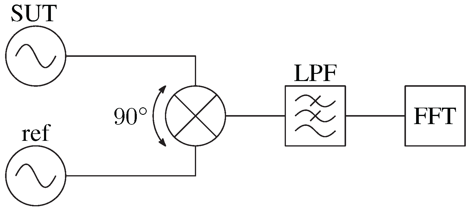
Figure 3.
Cross-correlation method. SUT: signal under test, XCORR: cross-correlation.
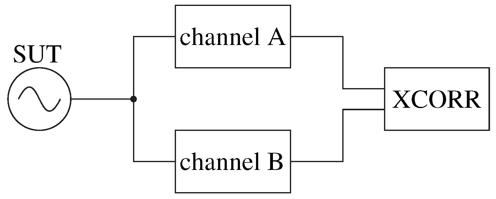
Figure 4.
Residual or interferometric method. DUT: device under test, LPF: low-pass filter, FFT: fast Fourier analyzer.
Figure 4.
Residual or interferometric method. DUT: device under test, LPF: low-pass filter, FFT: fast Fourier analyzer.
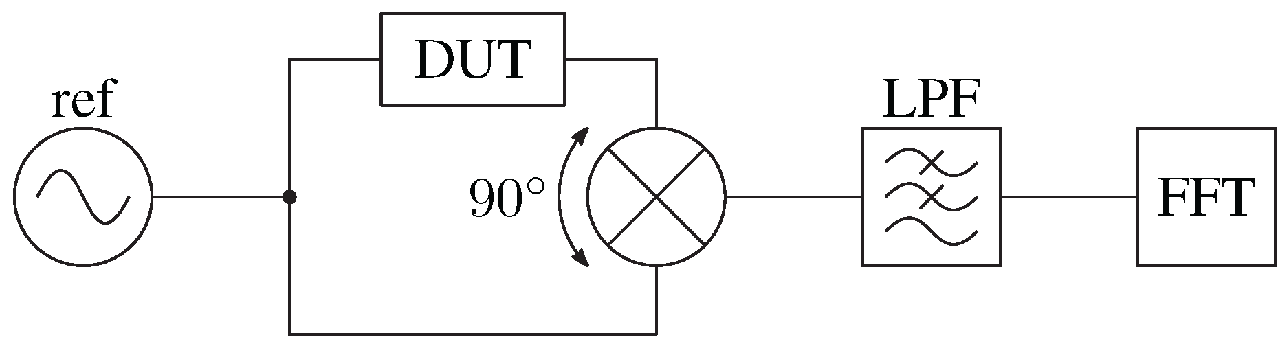
Figure 5.
Photonic delay-line method with delay implemented as an analog optical link. SUT: signal under test, VPS: variable phase shifter, FFT: fast-Fourier-transform analyzer, LD: laser diode, MZM: Mach-Zehnder modulator, PD: photodiode.
Figure 5.
Photonic delay-line method with delay implemented as an analog optical link. SUT: signal under test, VPS: variable phase shifter, FFT: fast-Fourier-transform analyzer, LD: laser diode, MZM: Mach-Zehnder modulator, PD: photodiode.

Figure 6.
a) Dual-parallel Mach-Zehnder modulator, b) Dual-polarization Mach-Zehnder modulator. PR: polarization rotator, PBC: polarization beam combiner.
Figure 6.
a) Dual-parallel Mach-Zehnder modulator, b) Dual-polarization Mach-Zehnder modulator. PR: polarization rotator, PBC: polarization beam combiner.

Figure 7.
Phase-noise measurement with a microwave photonic processor presented in [50], which utilizes both delay and phase tuning. SUT: signal-under-test, FFT: fast-Fourier-transform analyzer, PolM: polarization modulator, OBPF: optical band-pass filter, PC: polarization controller, Pol: polarizer.
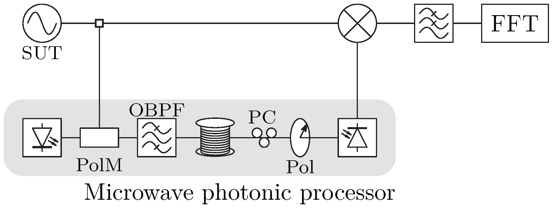
Figure 8.
Photonic-assisted phase shifter and delay utilized by dual-parallel MZM [51]. SUT: signal-under-test, FFT: fast-Fourier-transform analyzer, DP-MZM: dual-parallel Mach-Zehnder modulator, OBPF: optical band-pass filter.
Figure 8.
Photonic-assisted phase shifter and delay utilized by dual-parallel MZM [51]. SUT: signal-under-test, FFT: fast-Fourier-transform analyzer, DP-MZM: dual-parallel Mach-Zehnder modulator, OBPF: optical band-pass filter.
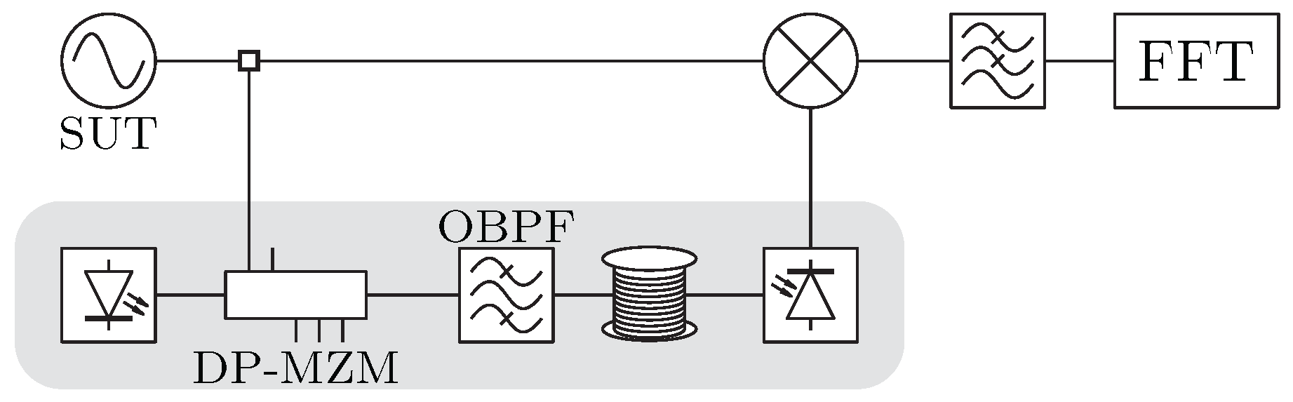
Figure 9.
Dual-fiber wavelength-tuned phase-noise measurement exploiting the chromatic dispersion of the fiber. SUT: signal under test, MZM: Mach-Zehnder modulator, FFT: fast-Fourier-transform analyzer.
Figure 9.
Dual-fiber wavelength-tuned phase-noise measurement exploiting the chromatic dispersion of the fiber. SUT: signal under test, MZM: Mach-Zehnder modulator, FFT: fast-Fourier-transform analyzer.

Figure 10.
Photonic downconverter presented in [60]. The photodiode functions as a phase detector, so the phase noise is downconverted directly from the optical domain to the baseband. SUT: signal under test, FFT: fast-Fourier-transform analyzer, PM: phase modulator, PC: polarization controller, MZM: Mach-Zehnder modulator, OBPF: optical bandpass filter.
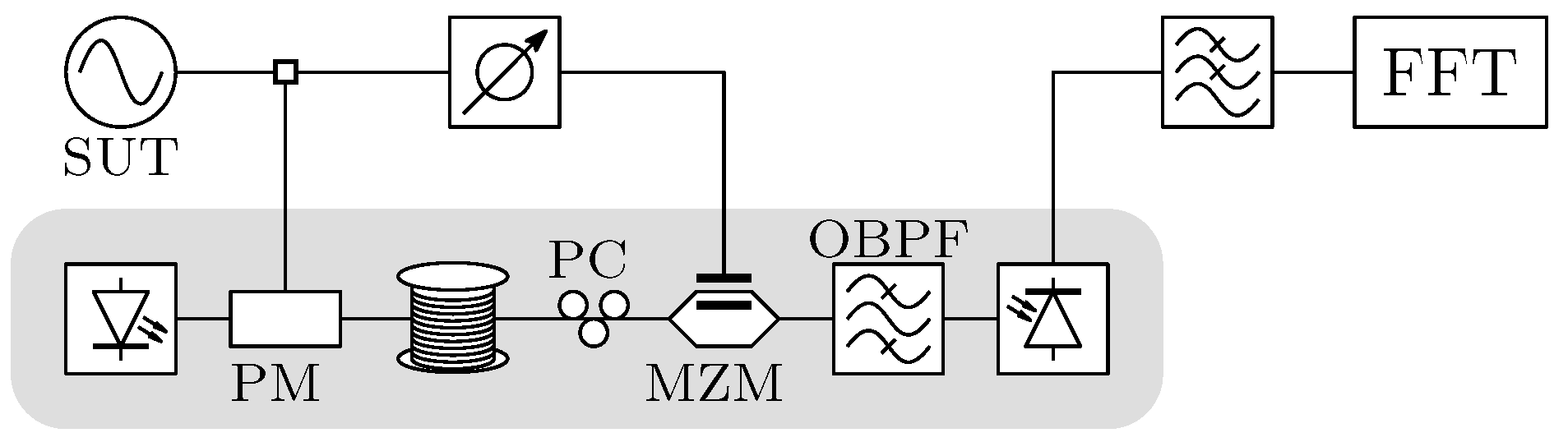
Figure 11.
Photonic-assisted phase-noise measurement presented in [61]. The delay, phase manipulation, and downconversion are all performed in the optical domain. SUT: signal under test, FFT: fast-Fourier-transform analyzer, PM: phase modulator, PolM: polarization modulator, OBPF: optical bandpass filter, PC: polarization controller, Pol: polarizer.
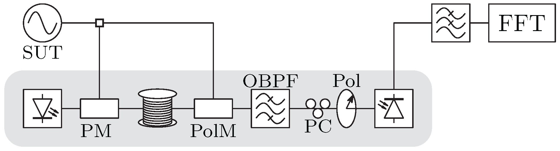
Figure 12.
Digitally demodulated phase-noise measurement with photonic delay and microwave IQ mixer, as presented in [64]. SUT: signal under test, VODL: variable optical delay line, ADC: analog-to-digital converter, DSP: digital signal processing, FFT: fast Fourier transform.
Figure 12.
Digitally demodulated phase-noise measurement with photonic delay and microwave IQ mixer, as presented in [64]. SUT: signal under test, VODL: variable optical delay line, ADC: analog-to-digital converter, DSP: digital signal processing, FFT: fast Fourier transform.
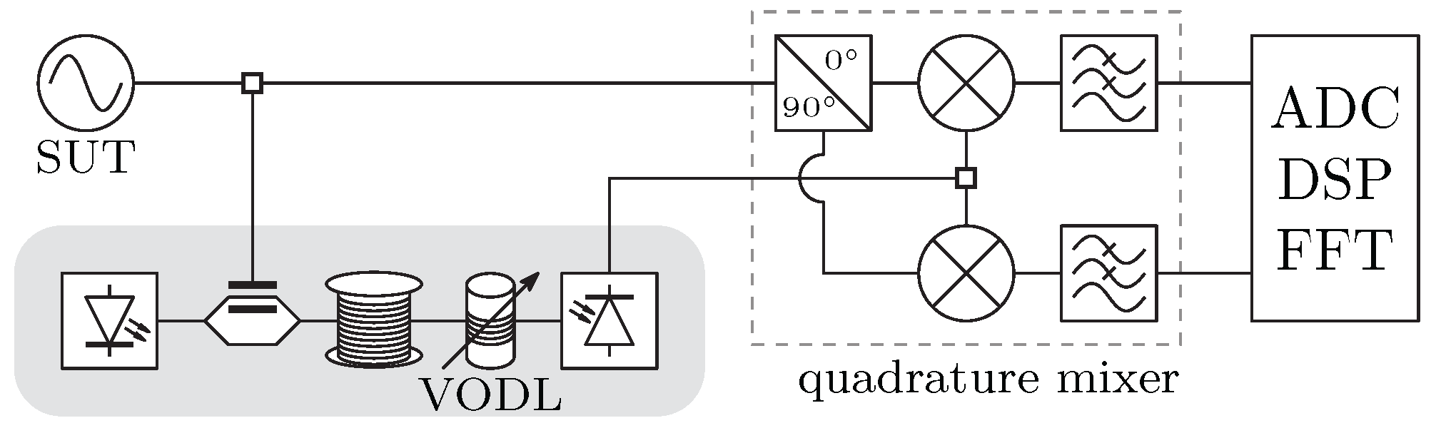
Figure 13.
Phase-noise measurement based on a photonic-assisted I/Q mixer presented in [65]. SUT: signal under test, PM: phase modulator, DPol-MZM: dual-polarization Mach-Zehnder modulator, OBPF: optical band-pass filter, PC: polarization controller, PBS: polarization beam splitter, ADC: analog-to-digital converter, DSP: digital signal processing, FFT: fast Fourier transform.
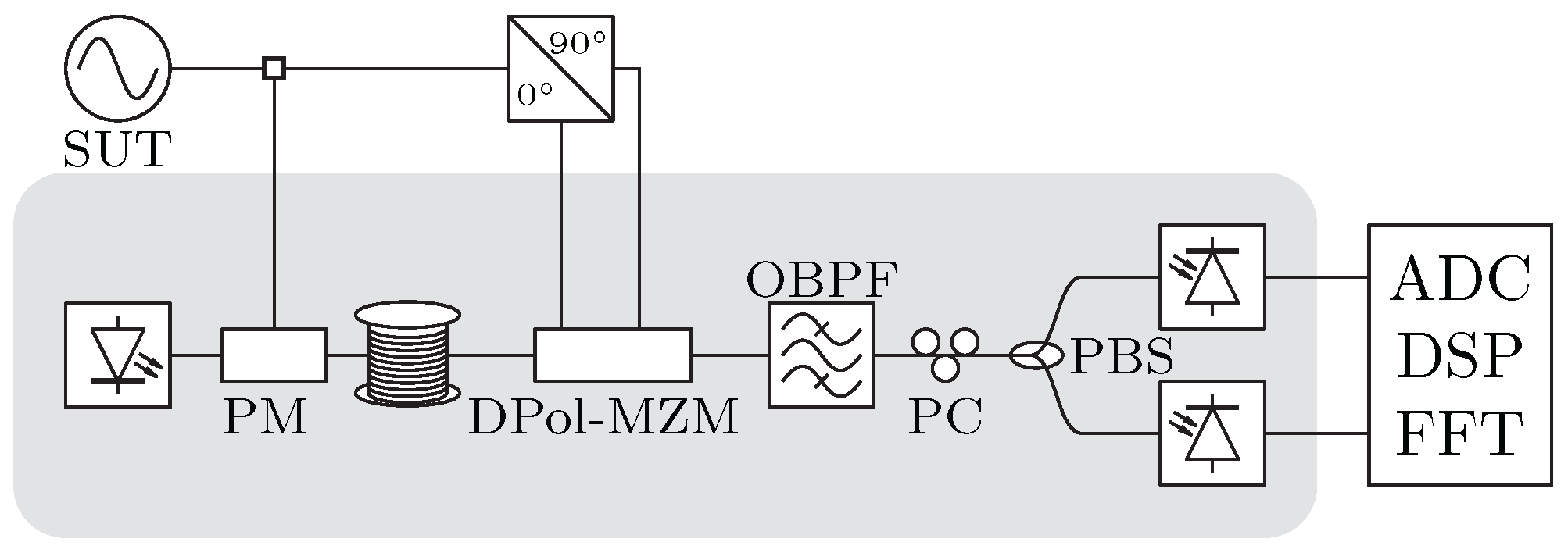
Figure 14.
Phase-noise measurement using an all-optical microwave I/Q mixer as presented in [66]. SUT: signal under test, PM: phase modulator, VODL: variable optical delay line, PC: polarization controller, PolM: polarization modulator, OBPF: optical band-pass filter, Pol: polarizer, ADC: analog-to-digital converter, DSP: digital signal processing, FFT: fast Fourier transform.
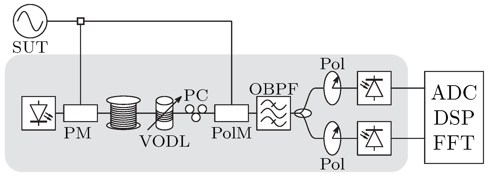
Figure 15.
Dual photonic-delay cross-correlation method presented in [69]. SUT: signal under test, VPS: variable phase shifter, FFT: fast-Fourier-transform analyzer, LD: laser diode, MZM: Mach-Zehnder modulator, PD: photodiode, XCORR: cross-correlation.
Figure 15.
Dual photonic-delay cross-correlation method presented in [69]. SUT: signal under test, VPS: variable phase shifter, FFT: fast-Fourier-transform analyzer, LD: laser diode, MZM: Mach-Zehnder modulator, PD: photodiode, XCORR: cross-correlation.
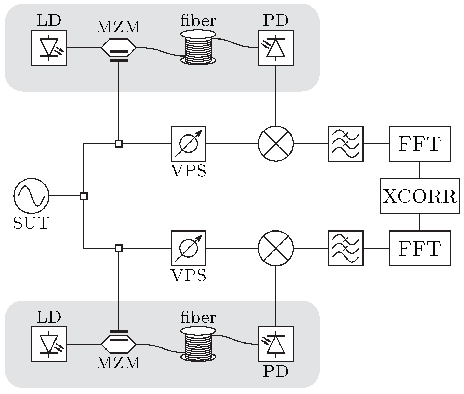
Figure 16.
Optical frequency comb-based self-heterodyne phase-noise measurement method presented in [77]. SUT: signal under test, OFCG: optical frequency comb generator, AOM: acusto-optic modulator, OBPF: optical bandpass filter, FFT: fast Fourier transform.
Figure 16.
Optical frequency comb-based self-heterodyne phase-noise measurement method presented in [77]. SUT: signal under test, OFCG: optical frequency comb generator, AOM: acusto-optic modulator, OBPF: optical bandpass filter, FFT: fast Fourier transform.
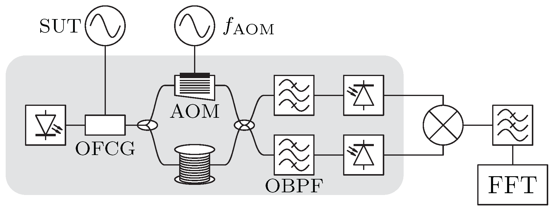
Figure 17.
Optical frequency comb-based self-calibrating and high-sensitivity phase noise measurement with optical I/Q detector, as presented in [80]. SUT: signal under test, OFCG: optical frequency comb generator, OBPF: optical bandpass filter, BPD: balanced photodiode, ADC: analog-to-digital converter, DSP: digital signal processing, FFT: fast Fourier transform.
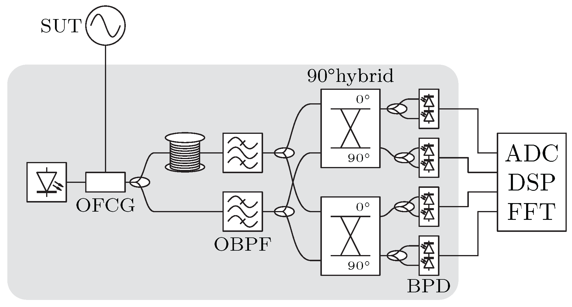
Figure 18.
Carrier-suppression scheme for low-level signal detection presented in [81]. The absence of a carrier at amplifier allows high gain without signal degradation.
Figure 18.
Carrier-suppression scheme for low-level signal detection presented in [81]. The absence of a carrier at amplifier allows high gain without signal degradation.
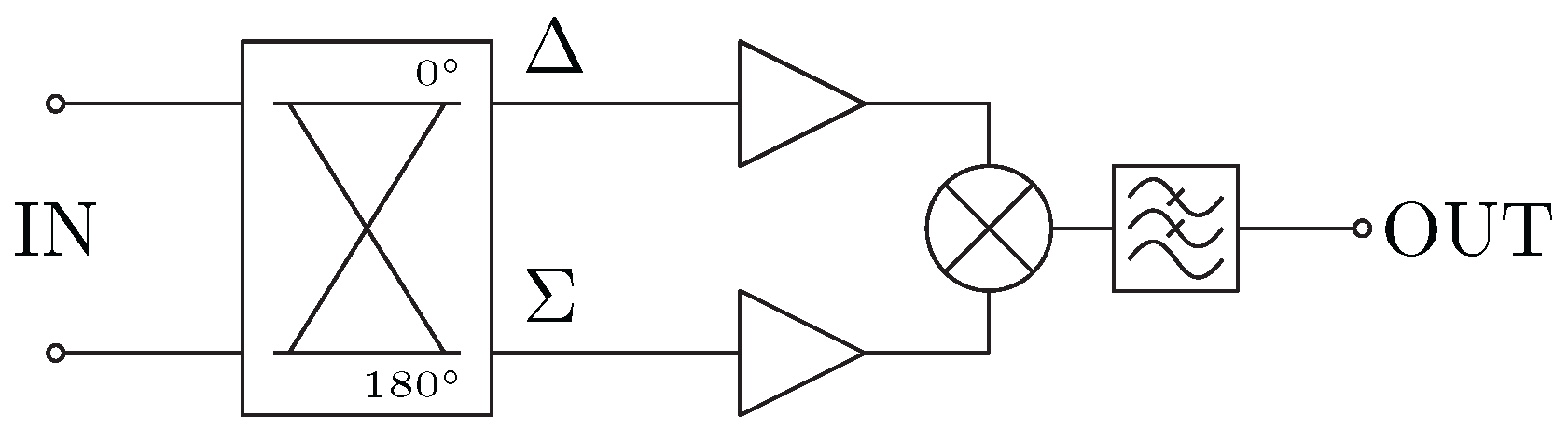
Figure 19.
Photonic delay-line method with delay-matched frequency translation presented in [84]. The two paths of the LO signal are delay-matched, which results in noise suppression when down-converting to the intermediate frequency. SUT: signal under test, LO: local oscillator, OBPF: optical bandpass filter, VODL: variable optical delay line, BPF: bandpass filter, FFT: fast Fourier transform analyzer.
Disclaimer/Publisher’s Note: The statements, opinions and data contained in all publications are solely those of the individual author(s) and contributor(s) and not of MDPI and/or the editor(s). MDPI and/or the editor(s) disclaim responsibility for any injury to people or property resulting from any ideas, methods, instructions or products referred to in the content. |
© 2025 by the authors. Licensee MDPI, Basel, Switzerland. This article is an open access article distributed under the terms and conditions of the Creative Commons Attribution (CC BY) license (http://creativecommons.org/licenses/by/4.0/).
Copyright: This open access article is published under a Creative Commons CC BY 4.0 license, which permit the free download, distribution, and reuse, provided that the author and preprint are cited in any reuse.


