
Submitted:
12 December 2025
Posted:
15 December 2025
You are already at the latest version
Abstract
The mechanical behavior of carbon-fiber-reinforced polymer (CFRP) laminates manu-factured using plasma-assisted solvolysis recycled fibers was evaluated experimentally through a comprehensive mechanical testing campaign. The plasma-assisted solvolysis parameters were selected based on an earlier sensitivity analysis that identified the optimal operating conditions for efficient matrix removal and fiber integrity preserva-tion. Prepregs made from both virgin and recycled carbon fibers were fabricated via a hand lay-up process and manually stacked to produce unidirectional laminates of identical nominal thickness. Longitudinal tension tests, longitudinal compression tests, and interlaminar shear strength (ILSS) tests were performed to assess the fundamental mechanical response of the recycled laminates and quantify the retention of mechanical properties relative to the virgin-reference material. Prior to mechanical testing, all laminates underwent ultrasonic C-scan inspection to assess manufacturing quality, detect internal defects, and identify any regions of poor consolidation. While both laminate types exhibited generally satisfactory quality, the recycled-fiber laminates showed a higher density of defects—such as localized voids and small delamination areas. The recycled laminates preserved around 80% of their original tensile strength and maintained an essentially unchanged elastic modulus. Compressive strength was more susceptible to imperfections introduced during remanufacturing, with the recy-cled laminates exhibiting roughly a 14% decrease compared with the virgin material. On the contrary, the compressive modulus was largely retained. The most substantial reduction occurred in ILSS, which dropped by 58%. The observed reduction in me-chanical properties of recycled CFRPs is mainly attributed to deviations in manufac-turing quality and not to the reduced properties of recycled carbon fibers.
Keywords:
recycling of thermoset CFRPs
; solvolysis
; plasma-assisted solvolysis
; mechanical testing
; ILSS
1. Introduction
Carbon-fiber-reinforced polymers (CFRPs) are increasingly employed across the aerospace, automotive, and energy sectors due to their exceptional specific strength, stiffness, and corrosion resistance [1]. Their superior mechanical performance enables substantial weight reduction and improved fuel efficiency in lightweight structural applications. In the rapidly expanding hydrogen-storage sector, high-pressure composite overwrapped pressure vessels (COPVs) manufactured with CFRPs have become the industry standard for vehicular and transport applications, offering up to 70% weight savings compared with conventional metallic tanks [2,3]. This widespread adoption underscores the strategic importance of CFRPs in meeting energy-efficiency and decarbonization targets across multiple industries [4,5,6].
With the rapid expansion of CFRP applications, end-of-life management has emerged as a critical challenge for the composites industry. Recent assessments estimate that global end-of-life waste from carbon-fiber composites may reach 500,000–840,000 tons per year by 2050, predominantly originating from retired aircraft and decommissioned wind-turbine components [7]. Current worldwide recycling capacity remains significantly below this projected volume, highlighting the urgent need for scalable recovery technologies and robust closed-loop strategies for fiber reuse [8]. The permanent cross-linked structure of thermoset matrices prevents remelting or reshaping, unlike thermoplastics, rendering conventional reprocessing routes infeasible and necessitating innovative recycling pathways to meet circular-economy and sustainability objectives [9].
Several recycling routes for CFRPs have been investigated. Mechanical recycling is economically attractive; however, it typically produces short and damaged fibers, leading to reduced composite strength and compromised interfacial adhesion [10,11]. Thermal methods, particularly pyrolysis, enable the recovery of longer fibers, but the process often leaves surface char or oxide residues that impair fiber–matrix bonding and diminish fiber strength [11,12,13]. Chemical recycling through solvolysis—the depolymerization of the thermoset matrix in reactive solvents—offers a more selective alternative capable of preserving fiber morphology and achieving high mechanical performance [11,14,15]. Recent solvolysis studies using acetic or formic acid, nitric acid, supercritical water/alcohol mixtures, and catalytic systems have reported resin removal efficiencies above 90% and fiber-strength retention of approximately 80–98% [16]. Nonetheless, these processes commonly require elevated temperatures, long reaction times, or aggressive chemical environments, which introduce challenges related to scalability, safety, and environmental sustainability.
To overcome these limitations, assisted solvolysis approaches—such as ultrasonic-, microwave-, and plasma-enhanced processes—are being developed to accelerate matrix degradation under milder operating conditions. Plasma-assisted solvolysis, in particular, combines oxidative chemical reactions with the action of reactive plasma species, thereby enhancing mass transport and promoting efficient polymer oxidation within the solvent phase. Recent studies using plasma-activated nitric acid have demonstrated complete epoxy removal within 3 to 6 hours at atmospheric pressure, while recovering fibers that retain or even exceed their original tensile properties [17,18]. These results indicate that plasma-enhanced solvolysis can substantially reduce energy demand and processing time without compromising fiber quality, positioning it as a promising next-generation recycling route for high-value CFRPs.
Despite considerable progress in fiber recovery, the remanufacturing of composites using recycled carbon fibers (rCFs) remains a major challenge—particularly when seeking mechanical performance comparable to virgin CFRPs. As discussed by Pimenta and Pinho [19], producing structural-grade composites from rCFs is still constrained by difficulties in achieving adequate fiber alignment, resin infiltration, and interfacial bonding, all of which limit the attainable mechanical properties. Zhang et al. [20] similarly noted that, although recycling technologies such as pyrolysis and solvolysis have advanced substantially, the transition from fiber recovery to large-scale composite remanufacturing is hindered by variability in fiber quality and limited control over downstream processing. Recent studies have therefore focused on assessing the mechanical performance of CFRP laminates remanufactured using rCF feedstocks. Ballout et al. [21], for example, fabricated laminates from fabrics reclaimed via mild solvolysis and reported performance retention of up to 93% relative to virgin composites, attributing the remaining reduction primarily to weaker fiber–matrix adhesion caused by the absence of sizing. Karuppannan and Kärki [22] also observed that thermally recycled fibers embedded in epoxy matrices preserved good tensile strength but exhibited lower interlaminar shear performance. Abdi et al. [23] emphasized that many current recycling routes induce fiber shortening, surface degradation, and misalignment, all of which compromise load-bearing capacity and interfacial bonding. Other researchers have examined how remanufacturing processes influence the resulting composite properties. Obunai et al. [24] reported that fibers recovered via superheated-steam pyrolysis led to reductions in bending and impact strength in the remanufactured laminates. Sato et al. [25] demonstrated that the mechanical response of rCF composites is highly sensitive to manufacturing quality, with fiber alignment, resin infiltration, and void content varying significantly across different fabrication routes and producing correspondingly wide variation in tensile modulus and stiffness. Sales-Contini et al. [26] and Theiss et al. [27] further showed that fiber alignment and orientation are critical determinants of mechanical performance in rCF laminates: manually fabricated laminates with insufficient alignment yielded limited tensile and flexural strengths, whereas highly oriented rCF tapes produced via automated fiber placement effectively restored structural-grade performance. Likewise, Cheng et al. [28] demonstrated that Cr₂O₃-assisted thermal recycling can yield fibers suitable for closed-loop remanufacturing, with the resulting laminates retaining more than 92% of the tensile and flexural strength of virgin CFRPs.
Although plasma-assisted solvolysis shows clear potential for efficient fiber recovery, its influence on the mechanical performance of remanufactured composites remains largely unexplored. To assess the suitability of recycled fibers for load-bearing applications, it is essential to evaluate laminate-level behavior under multiple loading modes—tension, compression, and interlaminar shear strength (ILSS)—which collectively govern structural reliability. Accordingly, the present study investigates the remanufacturing of CFRP coupons using fibers recovered via plasma-assisted solvolysis, followed by mechanical testing in tension, compression, and ILSS. The mechanical response of the recycled-fiber laminates is compared with that of virgin-fiber composites to quantify property retention and identify failure mechanisms associated with fiber–matrix interfaces. Additionally, the study examines fabrication-related challenges encountered during laminate production and highlights how processing quality influences the resulting performance of the recycled CFRPs. Overall, this work provides new insight into the structural potential of plasma-recycled carbon fibers and contributes to advancing circular, high-value composite materials.
2. Experimental
2.1. Materials
The CFRP materials examined in this study originated from filament-wound composite cylinders, a manufacturing technique commonly employed for pressure vessels and structural tubular components. The cylinders were produced by B&T Composites (Florina, Greece). Each specimen had a height of approximately 6.4–6.5 cm, an inner diameter of 5.5 cm, an outer diameter of 6.0 cm, and a wall thickness of about 0.25 cm. The volume of each cylinder was approximately 30 cm³, with a mass of 39 ± 2 g and a fiber content of 64 ± 3 wt%. The anhydride-cured epoxy matrix consisted of EPIKOTE™ Resin 828 in combination with EPIKURE™ Curing Agent 866 (Westlake Epoxy, Houston, TX, USA). This high-performance two-part epoxy system is widely used in aerospace-grade composite applications. EPIKOTE 828 is a bisphenol-A based liquid epoxy resin, whereas EPIKURE 866 is a liquid cycloaliphatic anhydride hardener. The system provides excellent mechanical strength, low curing shrinkage, strong adhesion to substrates, and high resistance to chemicals, acids, fuels, and solvents. The reinforcement phase consisted of TR30S carbon fibers (3K tows) supplied by Fibermax Ltd. (Greece) [29].
The newly manufactured CFRP used the same type of reinforcement, while the polymer matrix consisted of a two-part epoxy system (base resin: SR1700; hardener: SD2803) mixed at a weight ratio of 2.5:1, supplied by Sicomin Epoxy Systems (France) [30]. This bisphenol-A-based resin system exhibits a glass transition temperature of approximately 101 °C and is widely employed in high-performance composite structures due to its high stiffness, low water absorption, and strong fiber–matrix adhesion.
2.2. Plasma-Assisted Solvolysis Process
Figure 1 illustrates the plasma-assisted solvolysis setup used for recycling CFRPs. The system consists of a 2 L glass reactor vessel filled with concentrated nitric acid (65 wt%, Lachner, Neratovice, Czech Republic), capable of processing up to 1 kg of CFRP per batch. The glass reactor is placed on a grounded stainless-steel plate, which serves as the ground electrode. Four stainless-steel tube electrodes are positioned inside the reactor at the liquid surface and connected to a 30 kHz high-frequency power generator (IGBT143, Martignoni Elettrotecnica, Milano, Italy) and a 30 kV peak-to-peak voltage amplifier (IGBT163, Martignoni Elettrotecnica). Each electrode is enclosed within a glass tube that extends into the liquid and injects a controlled gas flow of 0.6 L/min, consisting of a nitrogen–argon mixture (1:4). The injected gas forms bubbles in which plasma is ignited, generating highly reactive chemical species capable of decomposing the polymer matrix of the composite. Real-time monitoring of the electrical parameters is performed using a passive voltage probe (1000:1, P6015A, Tektronix, Beaverton, OR, USA) and a passive current probe (1:1, Model 6585, Pearson Electronics, Palo Alto, CA, USA).
Before entering the plasma reactor, the composite materials undergo a pretreatment step in a dilute nitric acid solution (4–8 M) to initiate polymer swelling. During plasma treatment, the gases released from the reactor pass through two wet scrubber columns connected in series, each containing 1.5 L of scrubbing solution. The scrubber system, consisting of 0.01 M nitric acid and 0.06 M hydrogen peroxide, removes more than 80% of harmful NOₓ species from the exhaust stream. As the scrubber solution becomes enriched with nitrate compounds, it can be reused either as the pretreatment solution for subsequent batches or reintegrated into the main process stream. Once the polymer matrix is fully dissolved, the spent acid solution is regenerated for the next cycle by adding hydrogen peroxide, fresh 65% nitric acid, and the nitrate-enriched scrubber liquid. Throughout treatment, each CFRP specimen is held inside a stainless-steel cylindrical cage to minimize fiber damage, limit unwanted movement, and prevent entanglement or breakage of the continuous fibers. After complete matrix removal, the cages containing the recovered fibers are removed from the reactor and thoroughly rinsed with acetone followed by water to eliminate any remaining acid or polymer residues. The recovered continuous carbon fibers (100–120 m in length) are then transferred from the cylindrical cages onto industrial bobbins using a manual winding mechanism for storage and subsequent processing.
Prior to the present study, extensive experiments were conducted to optimize the operating conditions of the plasma-assisted solvolysis system with respect to the mechanical properties of the recovered single fibers [31], the processing time required for complete matrix dissolution, and the amount of NOₓ generated per gram of retrieved fibers. Based on our previous findings, operating at 1200 W with a 14.4 M HNO₃ solution was shown to minimize treatment time (≈6 h) and reduce NOₓ emissions per gram of recycled fibers, while ensuring that the recovered fibers retained mechanical properties comparable to those of virgin fibers [18,32].
2.3. Characterization of Recovered Fibers
The rCFs used for laminate remanufacturing were evaluated for their mechanical and interfacial properties prior to composite fabrication, following the same procedures described in [31]. Single-fiber tensile tests were performed using a Minimat 2000 micro-tensile apparatus with a 25 mm gauge length and a displacement rate of 2 mm/min, in accordance with ASTM C1557-14 [33]. Individual fibers were mounted on paper frames using epoxy adhesive to ensure proper alignment and avoid pre-loading. Based on the resulting stress–strain curves, the recycled fibers exhibited an average tensile strength of 2671.21 ± 573.82 MPa, a Young’s modulus of 223.08 ± 48.53 GPa, and an elongation at break of 1.67 ± 0.23%. The corresponding Weibull shape factor was approximately 4.6, indicating good reliability and limited data scatter. Compared with the virgin carbon fibers, the recycled fibers showed an increase of roughly 18% in tensile strength, an 11% improvement in modulus, and a modest increase of about 7% in elongation at break. Interfacial adhesion was assessed through microbond testing using Araldite LY5052 resin droplets. The measured interfacial shear strength (IFSS) averaged 40.54 MPa, representing a reduction of approximately 25% relative to the virgin reference. Although the IFSS exhibited a more pronounced decrease, all other measured properties—tensile strength, modulus, and elongation—were effectively maintained. Overall, the recovered fibers can be considered suitable for remanufacturing and serve as viable reinforcement for producing the recycled CFRP laminates examined in this study.
2.4. Manufacturing of Composite Laminates
Figure 2 provides an overview of the in-house CFRP manufacturing process, which was carried out by ADRINE (https://adrine.gr/). The fabrication of the composite prepregs began with the placement and alignment of carbon fibers in a single-lamina configuration to ensure uniform fiber distribution and orientation (Figure 3a). The fibers were arranged on a PMMA plastic mold covered with a PTFE release film. The fiber tow spacing was adjusted to achieve an areal density equivalent to that of a commercial unidirectional (UD) 3K carbon fiber fabric. Prepregs were produced using a hand lay-up technique (Figure 3b). The required quantity of epoxy resin was evenly distributed over the aligned fibers with a plastic spatula, ensuring sufficient impregnation. After impregnation, the samples were separated using PTFE films and subsequently stored at –18 °C.
The prepregs were subsequently stacked layer by layer to form composite laminates, with the number of layers selected to achieve the desired final thickness of the test coupons (Figure 3c). In this study, six prepreg layers were used to produce laminates of approximately 1 mm thick. The assembled layups were placed under vacuum to remove entrapped air and to ensure proper consolidation and were then cured for 24 h at room temperature under an applied pressure of 2 bar. A post-curing step followed for 16 h at 60 °C. All processing parameters were kept constant throughout the fabrication campaign to ensure consistent fiber volume fraction and dimensional accuracy of the manufactured plates.
The fiber volume fraction of the composite plies was determined using optical microscopy of polished CFRP cross-sections. Image-analysis software was employed to segment the carbon-fiber regions and calculate their area fraction relative to the total cross-sectional area, resulting in an estimated fiber volume fraction of approximately 58% (Figure 4).
2.5. Mechanical Testing
Mechanical characterization of the CFRP laminates manufactured with virgin carbon fibers (vCFs) and rCFs was performed to evaluate their tensile, compressive, and interlaminar shear properties. All tests were carried out using calibrated universal testing machines under controlled laboratory conditions, in accordance with the relevant ASTM standards.
The coupon dimensions were measured using a digital caliper with an accuracy of ±0.01 mm at three equally spaced locations along the gauge section. The values reported in Table 1 correspond to the mean and standard deviation obtained from five specimens per laminate type. No statistically significant dimensional differences were observed between the virgin and recycled coupons.
2.5.1. Tension Test
The tensile behavior of the laminates was characterized in accordance with ASTM D3039 using an MTS 100 kN universal testing machine equipped with wedge-action mechanical grips and an axial extensometer for strain measurement [34]. Rectangular coupons were cut from the unidirectional laminates to nominal dimensions of 250 mm × 25 mm × 1 mm (Figure 5). Each specimen was fitted with 56-mm-long GFRP end tabs bonded with a structural epoxy adhesive to promote uniform load transfer and prevent grip-induced failure. The testing configuration and specimen alignment at the start of the experiment are shown in Figure 6. Tensile loading was applied under displacement control at a crosshead rate of 2 mm/min, while load and strain were continuously recorded to generate the full stress–strain response. The tensile modulus, ultimate tensile strength, and elongation at break were subsequently derived from these measurements.
The tensile modulus (E) was obtained from the slope of the linear portion of the stress–strain curve. To ensure accurate strain measurement, at least one specimen from each material configuration was instrumented with back-to-back axial extensometers, enabling the assessment of bending effects during loading. The percentage of bending was computed at the mid-range of the chord modulus strain interval following the procedure defined in Equation (1). For tests in which bending remained below 3%, strain measurements from a single extensometer were deemed sufficient. In cases where bending exceeded this threshold, the average readings from the back-to-back sensors were used to provide a more reliable determination of the tensile modulus.
where is indicated strain from front transducer, is indicated strain from back transducer and is the percent bending in specimen.
2.5.2. Compression Test
The longitudinal compressive properties were evaluated in accordance with ASTM D3410 using the same MTS 100 kN universal testing machine [35]. Rectangular coupons measuring 140 mm × 15 mm × 1 mm were prepared and fitted with 62.5 mm-long end tabs to promote uniform load transfer and prevent premature gripping-related failure (Figure 7 and Figure 8). Tests were performed under displacement control at a crosshead rate of 1 mm/min, while axial load and displacement were continuously recorded to obtain the compressive stress–strain response.
During testing, axial and transverse strains were monitored using strain gauges bonded to the specimen surface to assess specimen alignment and ensure that bending remained below the 10% limit, following the same approach used for Eq. (1). The measured responses were subsequently used to determine the compressive modulus and compressive strength.
2.5.3. Interlaminar Shear Strength (ILSS) Test
The interlaminar shear strength was evaluated using the short-beam three-point bending method in accordance with ASTM D2344 [36]. Tests were conducted on a Tinius Olsen universal testing machine equipped with a dedicated three-point bending fixture configured with a span-to-thickness ratio of 4:1. The loading nose had a diameter of 6 mm, while the two lower cylindrical supports were 3 mm in diameter and positioned 3.5 mm from each specimen edge to ensure proper load transfer. Rectangular specimens were machined to nominal dimensions of 18 mm × 6 mm × 3 mm, with careful attention to maintaining parallel faces and uniform thickness (Figure 9a). Figure 9b illustrates the test setup at the beginning of the ILSS measurement. During testing, load and mid-span displacement were continuously recorded, and the interlaminar shear strength ( was computed using:
where is the maximum load at failure [N], is specimen width [mm], and is specimen thickness [mm].
3. Results
3.1. Non-Destructive Testing
Prior to mechanical testing, the CFRP laminates intended for tensile and compressive evaluation were examined using ultrasonic C-scan inspection to verify laminate integrity, identify internal defects, and assess overall manufacturing quality. The inspection was carried out as an off-line non-destructive evaluation (NDE) technique, meaning that measurements were performed after laminate fabrication. This approach enables detailed characterization of internal features—such as voids, delamination, inclusions, and regions of insufficient resin infiltration—thereby providing a reliable assessment of laminate uniformity.
The C-scan method is based on the detection of acoustic reflections generated at interfaces where mismatches in acoustic impedance occur. In this study, an immersion pulse–echo configuration was employed, using a 5 MHz transducer and a fixed gain setting for all scans to ensure consistent comparison across specimens. Representative amplitude maps were obtained for both virgin- and recycled-fiber laminates prepared for the tensile and compressive tests. For the ILSS coupons, however, no reliable C-scan data could be collected due to the small specimen dimensions, which limited the interpretability of the ultrasonic signal.
For the tensile specimens, the C-scan amplitude images of the virgin laminates (Figure 10) exhibited a predominantly red pattern with uniform signal intensity along the gauge length, indicative of effective resin impregnation and the absence of delamination or dry fiber regions. The recycled laminates showed a slightly more blue-shifted response, suggesting the presence of localized areas with reduced density, primarily near the specimen edges. Despite these minor variations, both laminate types demonstrated satisfactory manufacturing quality and good consolidation, with no major internal defects detected.
For the compressive specimens, the C-scan results (Figure 11) reveal a clear distinction in internal laminate quality between the virgin- and recycled-fiber composites. Unlike the virgin tensile coupons, the virgin compressive specimens—despite being produced with the same nominal thickness and lay-up—displayed scattered greenish regions indicative of slight interlaminar variations or minor delamination. These indications were more pronounced in the recycled compressive laminates, where larger and more continuous green zones appeared across the gauge section, particularly near the mid-thickness plane. Such localized voids or weakly bonded interfaces are known to facilitate premature micro-buckling and kink-band initiation under compressive loading. Overall, while all laminates preserved structural continuity, the recycled specimens exhibited a noticeably higher density of small defects, highlighting their increased susceptibility to void formation during fabrication.
3.2. Tensile Properties
Figure 12 compares the tensile stress-strain curves of virgin and recycled coupons. The tensile stress–strain responses of both laminate types exhibited a linear elastic region followed by brittle failure. However, the recycled specimens showed an earlier deviation from linearity, indicating premature damage initiation—likely in the form of microcracking and local fiber–matrix debonding—compared to the virgin composites. A similar early slope change in tensile curves of recycled carbon-fiber composites was reported by Becker et al. [37] for staple-fiber yarn systems, which they attributed to fiber misalignment and weaker interfacial bonding.
The virgin laminates achieved an average tensile strength of 1538.55 ± 57.49 Mpa, a modulus of 175.07 ± 13.45 Gpa, and an elongation at break of 1.42 ± 0.15%. In comparison, the recycled laminates reached 1236.43 ± 36.17 Mpa, 180.95 ± 18.24 Gpa, and 1.21 ± 0.11%.
Both laminate types exhibited explosive tensile failure, which is characteristic of unidirectional CFRPs loaded parallel to the fiber direction. As shown in Figure 13, the virgin specimen (failure type XGT) displayed a clean, centrally located fiber rupture with only minor delamination near the tab ends, indicating uniform load transfer and strong fiber–matrix adhesion. In contrast, the recycled specimen (failure type XGB) presented a more diffuse failure pattern, featuring extensive fiber pull-out, splintering, and localized delamination. These visual observations are consistent with the reduced tensile strength measured for the recycled laminates and highlight the role of interfacial quality and manufacturing-induced defects in governing the failure morphology.
3.3. Compressive Properties
Figure 14 compares the compressive stress-strain curves of virgin and recycled coupons. Virgin-fiber laminates reached an average compressive strength of 593.48 ± 60.17 Mpa, whereas the recycled-fiber specimens achieved 513.41 ± 58.92 Mpa, corresponding to a reduction of approximately 14%. The compressive modulus exhibited a more moderate decrease, retaining about 93% of the virgin material’s stiffness (116.30 ± 17.44 Gpa for virgin laminates compared with 108.39 ± 15.17 Gpa for the recycled ones). The ultimate compressive strain showed a similar trend, with virgin laminates reaching 0.74 ± 0.13%, while the recycled laminates recorded 0.67 ± 0.30%. These results confirm that, although stiffness is largely preserved, the compressive capacity of the recycled laminates is more sensitive to remanufacturing-induced defects such as voids and fiber misalignment.
Following compressive loading, both laminates exhibited brittle failure governed by fiber micro-buckling and matrix shear (Figure 15). The virgin specimen failed through a well-defined vertical kink band located near the mid-gauge region (failure type LGM), whereas the recycled laminate displayed a more irregular fracture pattern characterized by transverse splitting and partial delamination. This behavior indicates that local instabilities initiated at resin-deficient zones—previously identified in the C-scan—played a critical role in triggering failure (failure type TGV).
These differences confirm that imperfections introduced during the remanufacturing process, such as voids, slight fiber waviness, and weakly bonded interfaces, reduce the laminate’s ability to withstand compressive loads. In contrast to tensile behavior—which is fiber-dominated and largely reflects the intrinsic properties of the carbon fibers—the compressive response of unidirectional CFRPs is highly sensitive to matrix-related characteristics and defects. Imperfections such as delamination strongly influence the onset of micro-buckling and kink-band formation. Among these factors, inadequate fiber alignment remains one of the most critical limitations in recycled-fiber laminate fabrication, suggesting that controlled pre-treatment or improved fiber-orientation strategies could substantially enhance compressive performance [38].
3.4. ILSS Properties
Figure 16 compares the ILSS force-displacement curves of virgin and recycled coupons. The interlaminar shear strength tests revealed the most pronounced performance reduction. Virgin-fiber laminates exhibited an average ILSS of 66.42±1.88 MPa, while the recycled laminates reached about 28.07±3.13 MPa, corresponding to a 58% reduction.
After short-beam shear testing, both laminate types exhibited failure dominated by interlaminar shear (Figure 17). The virgin specimen failed along a clean shear plane near the mid-span with minimal fiber splitting, indicating efficient load transfer and strong fiber–matrix interfacial bonding. In contrast, the recycled specimen displayed multiple delaminations and extensive interlayer separation, reflecting weak fiber–matrix adhesion and poor shear load distribution. This markedly more severe delamination behavior is consistent with the substantial reduction in ILSS measured for the recycled composites. The degraded interfacial performance suggests that the absence of sizing on the recycled fibers and the presence of remanufacturing-induced defects significantly compromise shear resistance. Improvements in ILSS could be achieved through appropriate fiber-surface treatments or re-sizing procedures, as plasma-engineered interlayers have been shown to enhance interfacial shear strength [39].
4. Discussion
Table 2 summarizes the experimentally determined mechanical properties of the CFRP laminates manufactured from vCFs and rCFs.
The tensile results show that remanufacturing with plasma-recycled fibers led to a moderate reduction in strength and ductility, while the axial stiffness of the laminates was essentially preserved. Relative to the virgin composite, the recycled laminate retained approximately 80% of the tensile strength and exhibited a ~15% decrease in ultimate tensile strain, whereas the tensile modulus remained within the experimental scatter and was even slightly higher. This behavior reflects the fiber-dominated nature of the elastic response: the preserved single-fiber stiffness and comparable fiber volume fraction control the initial slope, while premature damage—driven by weaker interfaces, voids, and local misalignment—limits the ultimate strength and strain.
Similar trends have been documented in other studies on remanufactured CFRPs using recycled fibers, where tensile strength typically decreases but stiffness remains largely unaffected when fiber length and alignment are maintained. Sales-Contini et al. [26] reported reductions in tensile and flexural strength in pyrolysis-derived recycled composites relative to commercial CFRP. Sato et al. [25] observed improved fiber–matrix bonding in solvolysis-recycled systems, resulting in increased tensile strength and stiffness. Consistent with these findings, Sakai et al. [40] showed that nitric-acid-recycled fibers exhibited approximately 40% higher tensile strength compared with virgin fibers.
A two-tailed t-test (α = 0.05, n = 5) confirmed that the reductions in tensile strength and ultimate tensile strain for the recycled laminates are statistically significant, whereas the slight increase in tensile modulus is not. This supports the conclusion that elastic stiffness is effectively preserved, while damage onset and maximum load are more sensitive to recycling-related effects.
In compression, the recycled laminates exhibited lower average performance, with reductions of approximately 13% in compressive strength, 7% in compressive modulus, and 10% in ultimate compressive strain relative to the virgin material. However, due to the larger scatter and limited sample size (n = 5), none of these differences were found to be statistically significant. The observed reductions are consistent with the laminate quality indicated by C-scan and fracture analyses: the recycled specimens contained more voids and local delamination defects known to promote premature micro-buckling and kink-band formation in UD CFRPs. Since the remanufactured laminates use a fresh epoxy matrix, the reduced compressive performance cannot be attributed to matrix ageing, but instead to defects and weakened interfaces introduced during remanufacturing. This agrees with the literature, which emphasizes that compressive behavior in UD laminates is matrix- and defect-dominated and highly sensitive to fiber waviness and porosity—unlike the more fiber-dominated tensile response [41].
The most pronounced degradation was observed in the interlaminar shear strength, which decreased by nearly 60%. A two-tailed t-test confirmed that this reduction is statistically significant. This strong degradation is attributed mainly to weakened fiber–matrix adhesion and remanufacturing-induced defects such as voids, local resin-poor regions, and the absence of fiber sizing. As ILSS is known to be highly interface-dominated [42], the severe reduction reported here highlights the current limitations of the remanufacturing route and suggests that fiber surface treatments or resizing will be required to restore interlaminar performance closer to that of virgin composites.
5. Conclusions
This study evaluated the mechanical performance of unidirectional CFRP laminates produced using carbon fibers recovered through plasma-assisted solvolysis. The results collectively demonstrate that plasma-based solvolysis enables efficient resin removal and the recovery of clean, continuous fibers that are suitable for composite remanufacturing. Although the recycled laminates exhibited moderate reductions in mechanical properties relative to the virgin references, their overall behavior remained consistent and structurally reliable, confirming the potential of the recovered fibers for use in load-bearing composite applications. The observed reductions are attributed primarily to manufacturing challenges encountered during remanufacturing. The main conclusions can be summarized as follows:
- The recycled laminates retained approximately 80% of the tensile strength and exhibited a ~15% reduction in ultimate strain, while the elastic modulus remained essentially unchanged.
- Compressive strength proved more sensitive to remanufacturing-induced imperfections, with the recycled laminates showing a ~14% reduction compared with the virgin material. Despite this reduction in strength, the compressive modulus was largely retained.
- The most pronounced degradation was observed in ILSS, which decreased by 58%. This reduction reflects the absence of sizing on the recycled fibers and the resulting weaker fiber–matrix interfacial adhesion. Failure occurred through multiple delamination areas and interlayer separations. The reduced ILSS highlights a key limitation of the current remanufacturing route. To address this, future work should incorporate appropriate fiber surface treatments or re-sizing procedures to enhance interfacial bonding and restore interlaminar shear performance.
Author Contributions
Conceptualization, I.T., K.T., D.M, E.F., E.A., N.K., and P.P.; methodology, I.T., K.T., D.M, E.F., and E.A.; software, I.T., K.T., D.M, E.F., E.A., N.K., and P.P.; validation, I.T., K.T., D.M, E.F., E.A., N.K., and P.P.; formal analysis, I.T.; investigation, I.T.; resources, I.T., K.T., D.M, E.F., E.A., N.K., and P.P.; data curation, I.T.; writing—original draft preparation, I.T., D.M, E.F. and N.K.; writing—review and editing, K.T., E.A. and P.P.; visualization, I.T., D.M and N.K.; supervision, K.T. and E.A.; project administration, K.T., E.F., and E.A.; funding acquisition, K.T., and E.A. All authors have read and agreed to the published version of the manuscript.
Funding
This research was implemented in the framework of H.F.R.I call “Basic research Financing (Horizontal support of all Sciences)” under the National Recovery and Resilience Plan “Greece 2.0” funded by the European Union – NextGenerationEU (H.F.R.I. Project Number: 15231).
Data Availability Statement
All data are presented in the manuscript.
Conflicts of Interest
The authors declare no conflicts of interest.
References
- Revolutionizing Aircraft Materials and Processes; Pantelakis, S., Tserpes, K., Eds.; Springer International Publishing: Cham, 2020; ISBN 978-3-030-35345-2. [Google Scholar]
- Bai, J.; Fan, H.; Ke, Q.; Luo, F.; Chen, J.; Peng, L.; Ding, Y.; Zhang, J.; Zhang, G.; Yang, M. High Performance Epoxy Composites Modified by a Ladder-like Polysilsesquioxane. Compos. Commun. 2024, 46, 101813. [Google Scholar] [CrossRef]
- Eko, A.J.; Epaarachchi, J.; Jewewantha, J.; Zeng, X. A Review of Type IV Composite Overwrapped Pressure Vessels. Int. J. Hydrog. Energy 2025, 109, 551–573. [Google Scholar] [CrossRef]
- Composite Waste: Understanding Regulations and Finding Circular Solutions for a Growing Problem. Available online: https://www.circularise.com/blogs/composite-waste-understanding-regulations-and-finding-circular-solutions-for-a-growing-problem (accessed on 8 July 2025).
- Vogiantzi, C.; Tserpes, K. On the Definition, Assessment, and Enhancement of Circular Economy across Various Industrial Sectors: A Literature Review and Recent Findings. Sustainability 2023, 15, 16532. [Google Scholar] [CrossRef]
- Anagnostopoulou, A.; Sotiropoulos, D.; Tserpes, K. A Robust Sustainability Assessment Methodology for Aircraft Parts: Application to a Fuselage Panel. Sustainability 2025, 17, 3299. [Google Scholar] [CrossRef]
- Chen, P.-Y.; Feng, R.; Xu, Y.; Zhu, J.-H. Recycling and Reutilization of Waste Carbon Fiber Reinforced Plastics: Current Status and Prospects. Polymers 2023, 15, 3508. [Google Scholar] [CrossRef]
- Fairmat (When) Is Recycling Composites Worth It? Fairmat. 2023.
- Post, W.; Susa, A.; Blaauw, R.; Molenveld, K.; Knoop, R.J.I. A Review on the Potential and Limitations of Recyclable Thermosets for Structural Applications. Polym. Rev. 2020, 60, 359–388. [Google Scholar] [CrossRef]
- Aldosari, S.M.; AlOtaibi, B.M.; Alblalaihid, K.S.; Aldoihi, S.A.; AlOgab, K.A.; Alsaleh, S.S.; Alshamary, D.O.; Alanazi, T.H.; Aldrees, S.D.; Alshammari, B.A. Mechanical Recycling of Carbon Fiber-Reinforced Polymer in a Circular Economy. Polymers 2024, 16, 1363. [Google Scholar] [CrossRef]
- Vogiantzi, C.; Tserpes, K. A Comparative Environmental and Economic Analysis of Carbon Fiber-Reinforced Polymer Recycling Processes Using Life Cycle Assessment and Life Cycle Costing. J. Compos. Sci. 2025, 9, 39. [Google Scholar] [CrossRef]
- Hao, S.; He, L.; Liu, J.; Liu, Y.; Rudd, C.; Liu, X. Recovery of Carbon Fibre from Waste Prepreg via Microwave Pyrolysis. Polymers 2021, 13, 1231. [Google Scholar] [CrossRef]
- Vogiantzi, C.; Tserpes, K.; Ngungu, X.; Van Haute, Q. Characterization of Carbon Fibers Recovered from 3D Woven CFRPs via Pyrolysis and Solvolysis. J. Compos. Mater. 2025, 00219983251404984. [Google Scholar] [CrossRef]
- Branfoot, C.; Folkvord, H.; Keith, M.; Leeke, G.A. Recovery of Chemical Recyclates from Fibre-Reinforced Composites: A Review of Progress. Polym. Degrad. Stab. 2023, 215, 110447. [Google Scholar] [CrossRef]
- Vogiantzi, C.; Tserpes, K. A Preliminary Investigation on a Water- and Acetone-Based Solvolysis Recycling Process for CFRPs. Materials 2024, 17, 1102. [Google Scholar] [CrossRef]
- Xing, M.; Li, Z.; Zheng, G.; Du, Y.; Chen, C.; Wang, Y. Recycling of Carbon Fiber-Reinforced Epoxy Resin Composite via a Novel Acetic Acid Swelling Technology. Compos. Part B Eng. 2021, 224, 109230. [Google Scholar] [CrossRef]
- Marinis, D.; Farsari, E.; Alexandridou, C.; Amanatides, E.; Mataras, D. Chemical Recovery of Carbon Fibers from Composites via Plasma Assisted Solvolysis. J. Phys. Conf. Ser. 2024, 2692, 012017. [Google Scholar] [CrossRef]
- Marinis, D.; Markatos, D.; Farsari, E.; Amanatides, E.; Mataras, D.; Pantelakis, S. A Novel Plasma-Enhanced Solvolysis as Alternative for Recycling Composites. Polymers 2024, 16, 2836. [Google Scholar] [CrossRef]
- Pimenta, S.; Pinho, S.T. Recycling Carbon Fibre Reinforced Polymers for Structural Applications: Technology Review and Market Outlook. Waste Manag. 2011, 31, 378–392. [Google Scholar] [CrossRef]
- Zhang, J.; Chevali, V.S.; Wang, H.; Wang, C.-H. Current Status of Carbon Fibre and Carbon Fibre Composites Recycling. Compos. Part B Eng. 2020, 193, 108053. [Google Scholar] [CrossRef]
- Ballout, W.; Sallem-Idrissi, N.; Sclavons, M.; Doneux, C.; Bailly, C.; Pardoen, T.; Van Velthem, P. High Performance Recycled CFRP Composites Based on Reused Carbon Fabrics through Sustainable Mild Solvolysis Route. Sci. Rep. 2022, 12, 5928. [Google Scholar] [CrossRef]
- Karuppannan Gopalraj, S.; Kärki, T. A Study to Investigate the Mechanical Properties of Recycled Carbon Fibre/Glass Fibre-Reinforced Epoxy Composites Using a Novel Thermal Recycling Process. Processes 2020, 8, 954. [Google Scholar] [CrossRef]
- Abdi, B.; Wang, Y.; Gong, H.; Su, M. Recycling, Remanufacturing and Applications of Semi-Long and Long Carbon Fibre from Waste Composites: A Review. Appl. Compos. Mater. 2025, 32, 1237–1265. [Google Scholar] [CrossRef]
- Obunai, K.; Okubo, K. Mechanical Characteristics of Reclaimed Carbon Fibre under Superheated Steam Atmosphere and Its Feasibility for Remanufacturing CFRP/CFRTP. Compos. Part Appl. Sci. Manuf. 2024, 176, 107843. [Google Scholar] [CrossRef]
- Sato, M.; Kataoka, Y.; Higashide, M.; Ishida, Y.; Sugimoto, S. Evaluation of the Mechanical Properties of Highly Oriented Recycled Carbon Fiber Composites Using the Vacuum-Assisted Resin Transfer Molding, Wet-Layup, and Resin Transfer Molding Methods. Polymers 2025, 17, 1293. [Google Scholar] [CrossRef]
- Sales-Contini, R.C.M.; Costa, H.M.S.; Bernardi, H.H.; Menezes, W.M.M.; Silva, F.J.G. Mechanical Strength and Surface Analysis of a Composite Made from Recycled Carbon Fibre Obtained via the Pyrolysis Process for Reuse in the Manufacture of New Composites. Materials 2024, 17, 423. [Google Scholar] [CrossRef]
- Theiss, J.; Haj Ahmad, P.; Manis, F.; Preinfalck, M.; Baz, S. Mechanical Properties of Highly Oriented Recycled Carbon Fiber Tapes Using Automated Fiber Placement. J. Compos. Sci. 2025, 9, 425. [Google Scholar] [CrossRef]
- Cheng, H.; Zhou, J.; Guo, L.; Wang, H.; Wang, Q.; Tang, M.; Qian, Z. Investigation on Recycling and Remanufacturing of the Carbon Fiber Composites Based on Thermally Activated Cr2O3. J. Clean. Prod. 2023, 427, 139133. [Google Scholar] [CrossRef]
- Δέσμη ανθρακονημάτων 3Κ, 1.80 kg, 5 km. Available online: https://www.fibermax.eu/el-gr/anthrakoyfasmata/nimata/nimata-provoli-olon/desmi-anthrakonimaton-3k-1-kg-5-km.html (accessed on 26 June 2025).
- SR 1700 - System for Manufacturing Composite Structures. Sicomin.
- Tourkantoni, I.; Tserpes, K.; Marinis, D.; Farsari, E.; Amanatides, E. Mechanical Characterization of Carbon Fibers and Their Interfaces Recycled Through Plasma-Assisted Solvolysis Under Different Processing Conditions. [CrossRef]
- Marinis, D.; Tourkantoni, I.; Farsari, E.; Amanatides, E.; Tserpes, K. Effect of Process Parameters on Plasma-Enhanced Solvolysis of CFRPs. Materials 2025, 18, 5081. [Google Scholar] [CrossRef] [PubMed]
- C28 Committee ASTM International. Test Method for Tensile Strength and Youngs Modulus of Fibers. [CrossRef]
- D30 Committee ASTM International. Test Method for Tensile Properties of Polymer Matrix Composite Materials. [CrossRef]
- D30 Committee ASTM International. Test Method for Compressive Properties of Polymer Matrix Composite Materials with Unsupported Gage Section by Shear Loading. [CrossRef]
- D30 Committee ASTM International. Test Method for Short-Beam Strength of Polymer Matrix Composite Materials and Their Laminates. [CrossRef]
- Becker, C.; Hausmann, J.; Krummenacker, J.; Motsch-Eichmann, N. First Conclusions on Damage Behaviour of Recycled Carbon Staple Fibre Yarn Using X-Ray and Acoustic Emission Techniques. Materials 2023, 16, 4842. [Google Scholar] [CrossRef] [PubMed]
- Longana, M.L.; Yu, H.; Hamerton, I.; Potter, K.D. Development and Application of a Quality Control and Property Assurance Methodology for Reclaimed Carbon Fibers Based on the HiPerDiF (High Performance Discontinuous Fibre) Method and Interlaminated Hybrid Specimens. Adv. Manuf. Polym. Compos. Sci. 2018, 4, 48–55. [Google Scholar] [CrossRef]
- Knob, A.; Lukes, J.; Drzal, L.; Cech, V. Further Progress in Functional Interlayers with Controlled Mechanical Properties Designed for Glass Fiber/Polyester Composites. Fibers 2018, 6, 58. [Google Scholar] [CrossRef]
- Sakai, A.; Kurniawan, W.; Kubouchi, M. Chemical Recycling of CFRP in an Environmentally Friendly Approach. Polymers 2024, 16, 143. [Google Scholar] [CrossRef] [PubMed]
- Berbinau, P.; Soutis, C.; Guz, I.A. Compressive Failure of 0 Unidirectional Carbon-Æbre-Reinforced Plastic (CFRP) Laminates by Æbre Microbuckling.
- Kim, Y.N.; Kim, Y.-O.; Kim, S.Y.; Park, M.; Yang, B.; Kim, J.; Jung, Y.C. Application of Supercritical Water for Green Recycling of Epoxy-Based Carbon Fiber Reinforced Plastic. Compos. Sci. Technol. 2019, 173, 66–72. [Google Scholar] [CrossRef]
Figure 1.
Plasma-assisted solvolysis flowchart.
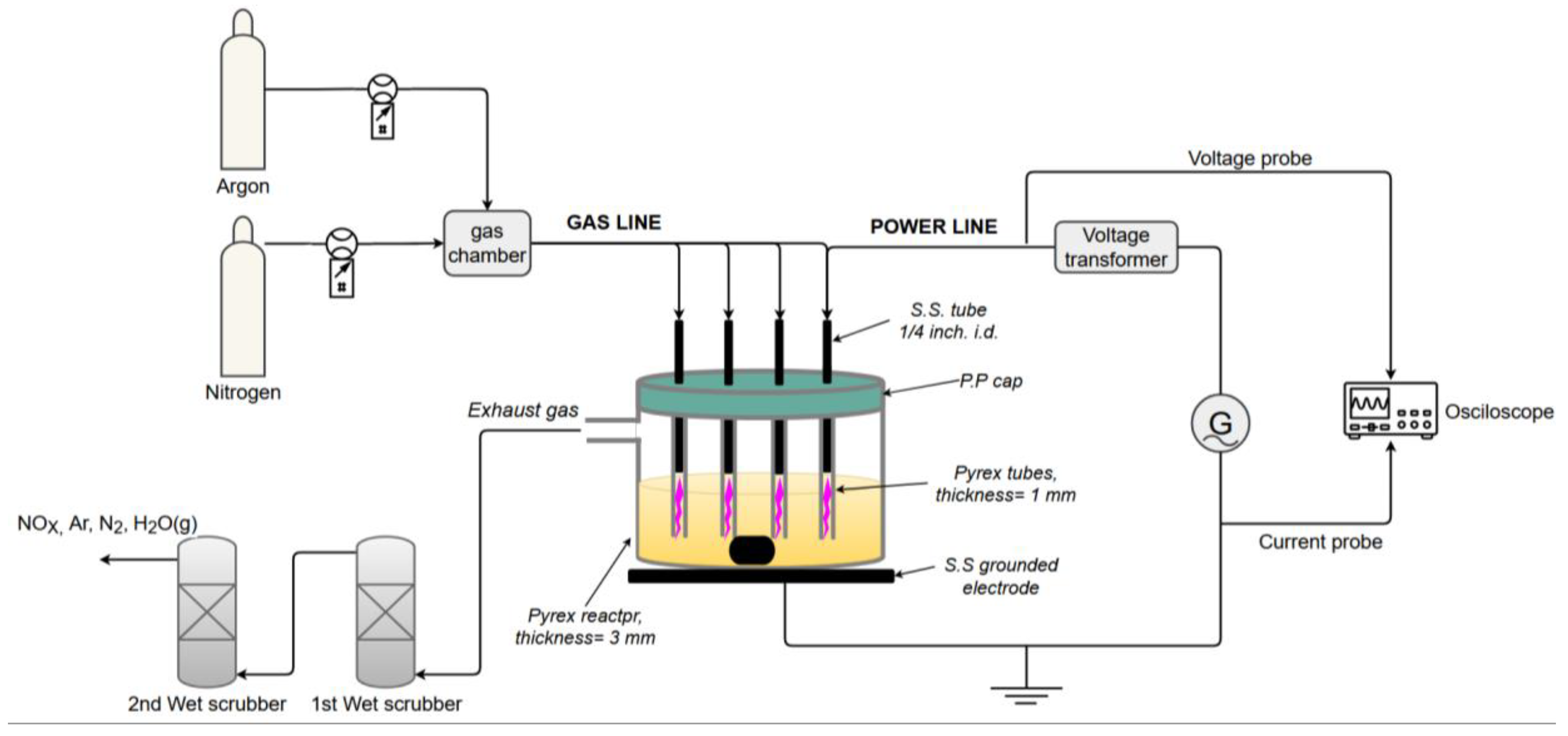
Figure 2.
Schematic illustration of the CFRP fabrication process.
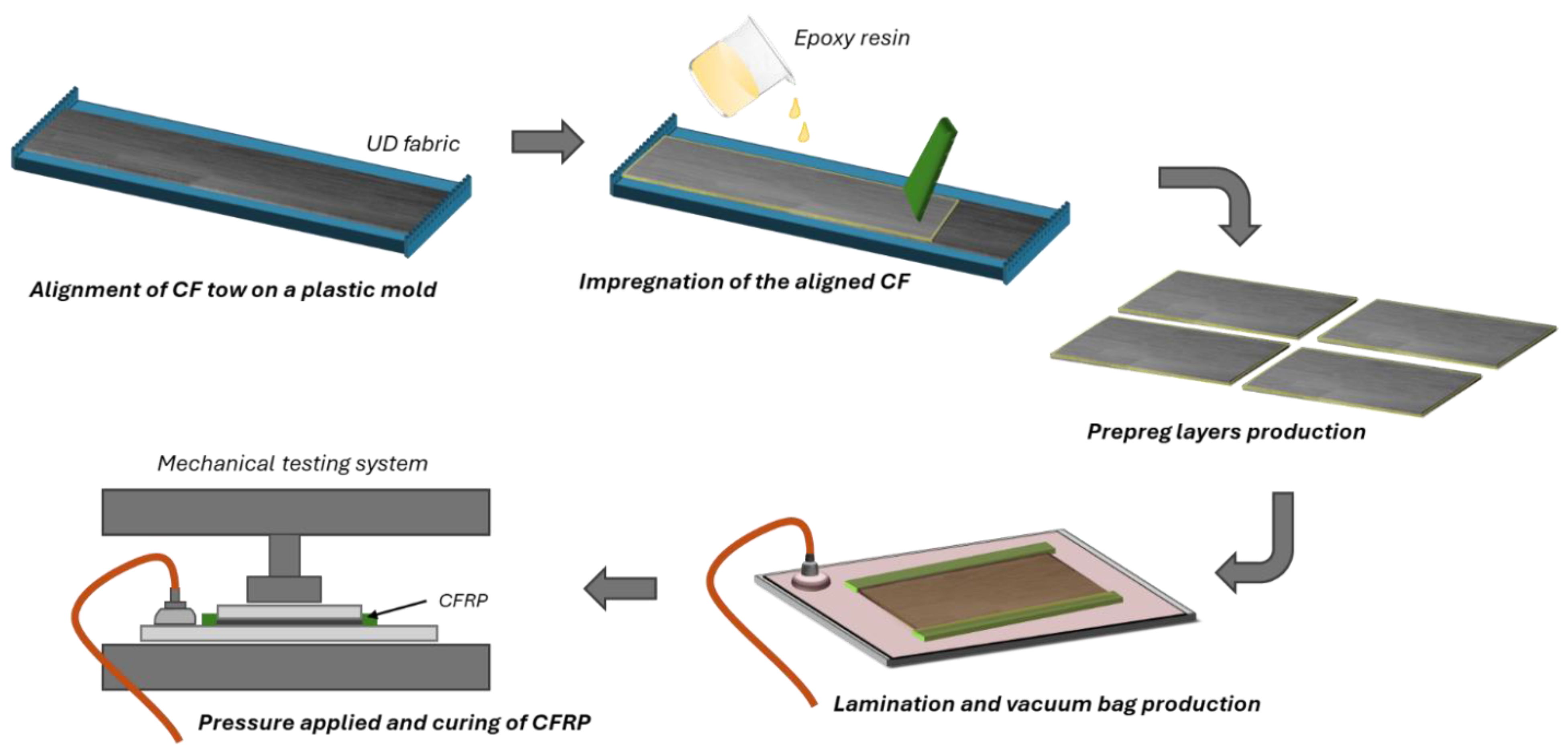
Figure 3.
(a) The tailor-made fiber alignment PMMA mold with the laser-processed spacers; (b) the CFRP prepreg (single layer), before lamination, and (c) vacuum bagging of the six-layer composite plate.
Figure 3.
(a) The tailor-made fiber alignment PMMA mold with the laser-processed spacers; (b) the CFRP prepreg (single layer), before lamination, and (c) vacuum bagging of the six-layer composite plate.
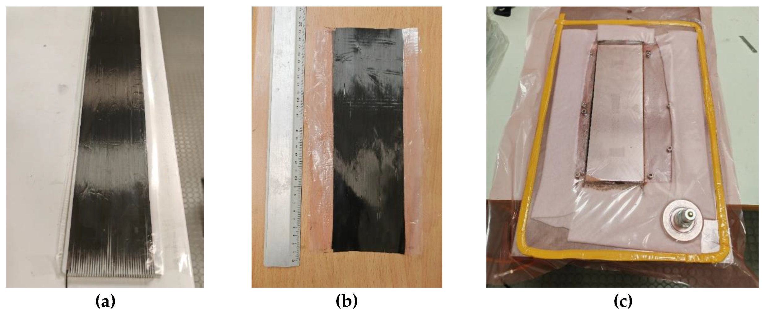
Figure 4.
Optical microscopy image of the cross-sectional area of a 6 ply CFRP produced with recycled carbon fibers.
Figure 4.
Optical microscopy image of the cross-sectional area of a 6 ply CFRP produced with recycled carbon fibers.
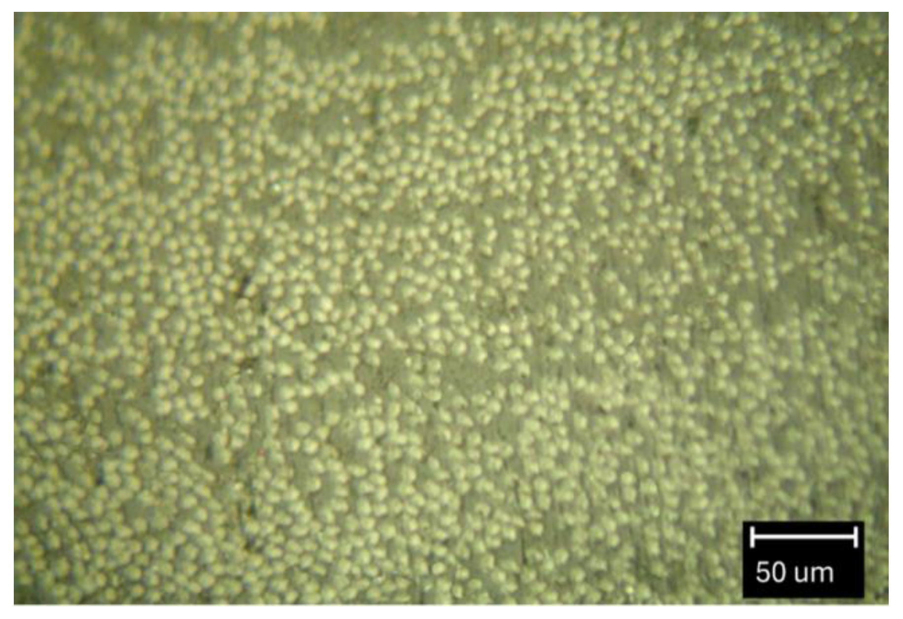
Figure 5.
The coupons used for the tension tests (vCFs).
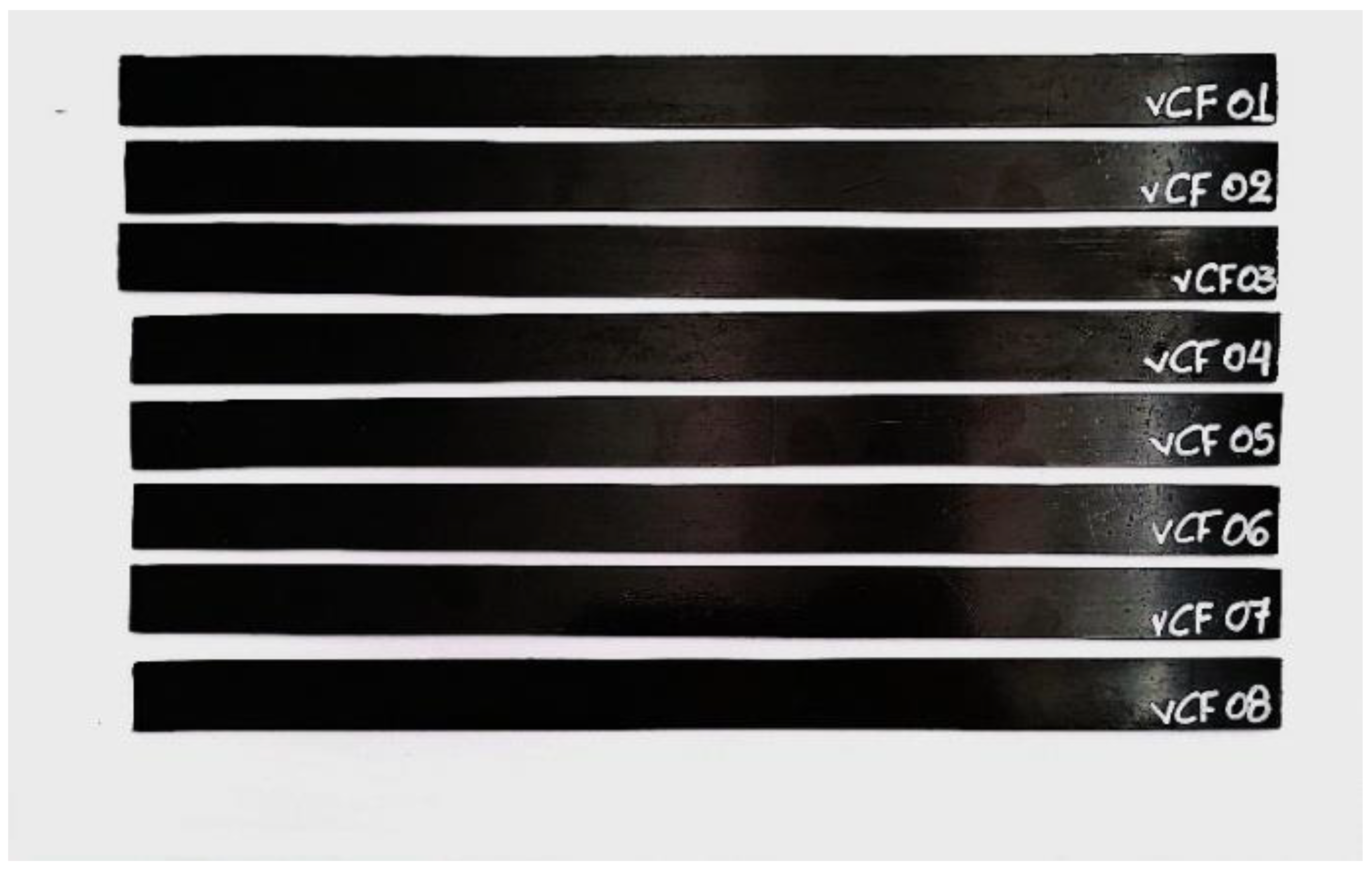
Figure 6.
Photo of the tension test.
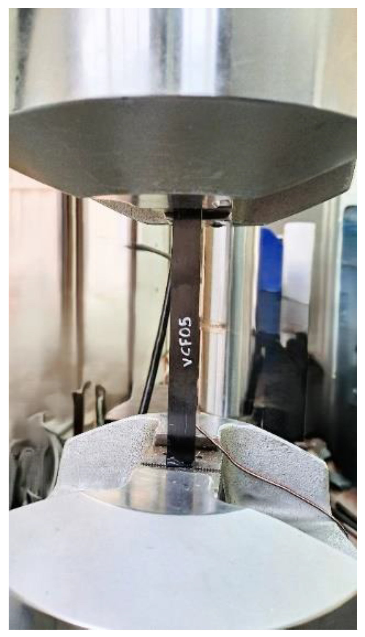
Figure 7.
The compression specimens which were used for compressive testing.
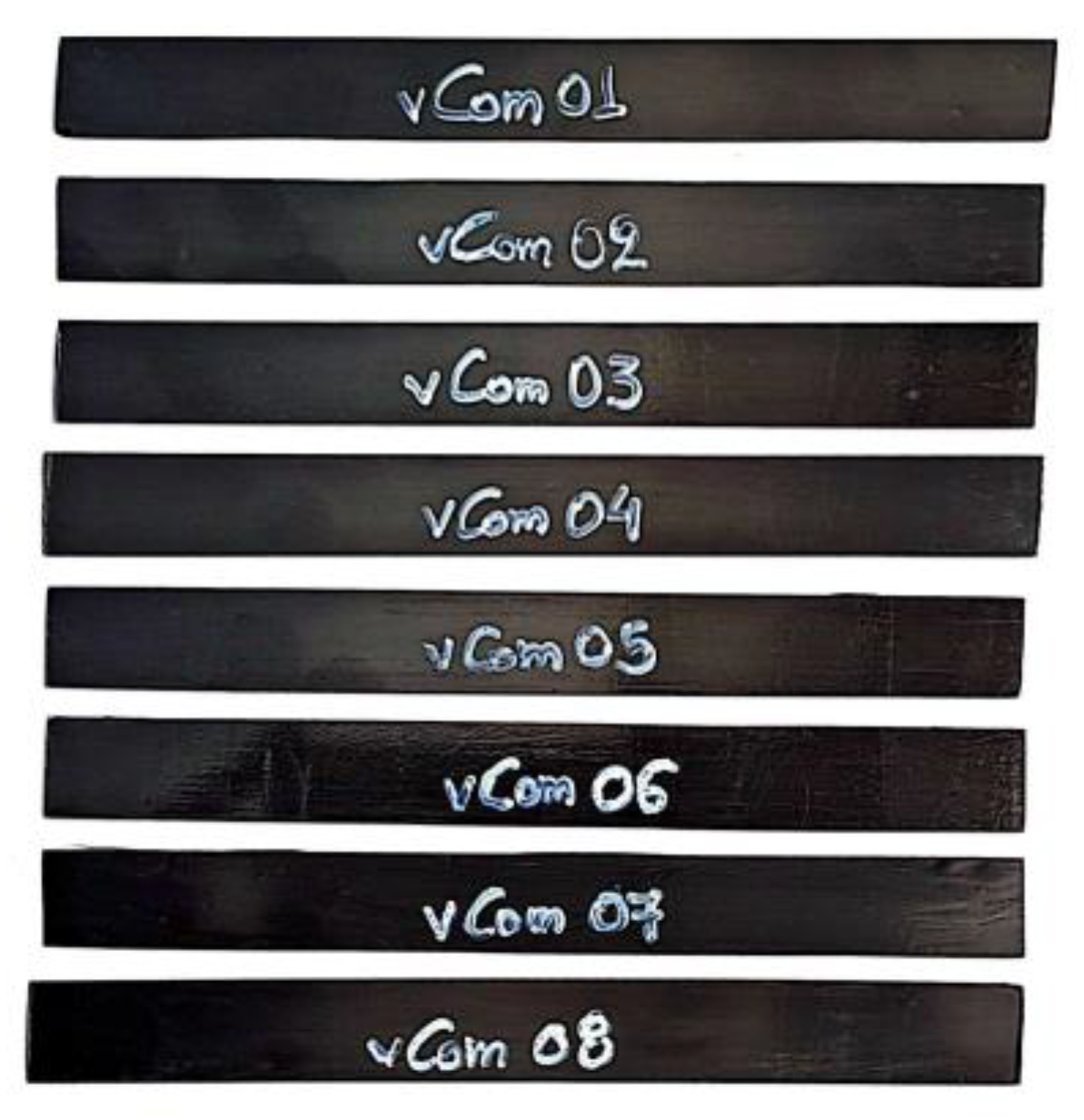
Figure 8.
A compression specimen with end tabs.
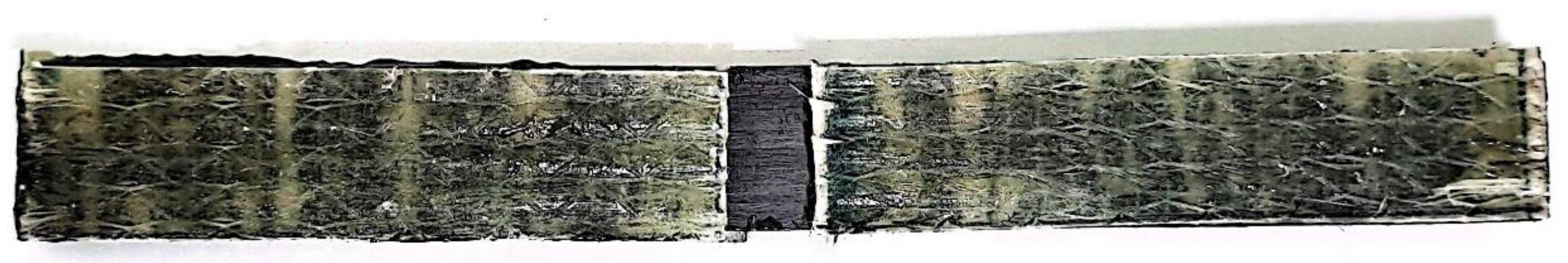
Figure 9.
Experiment initialization at the apparatus for ILSS test.
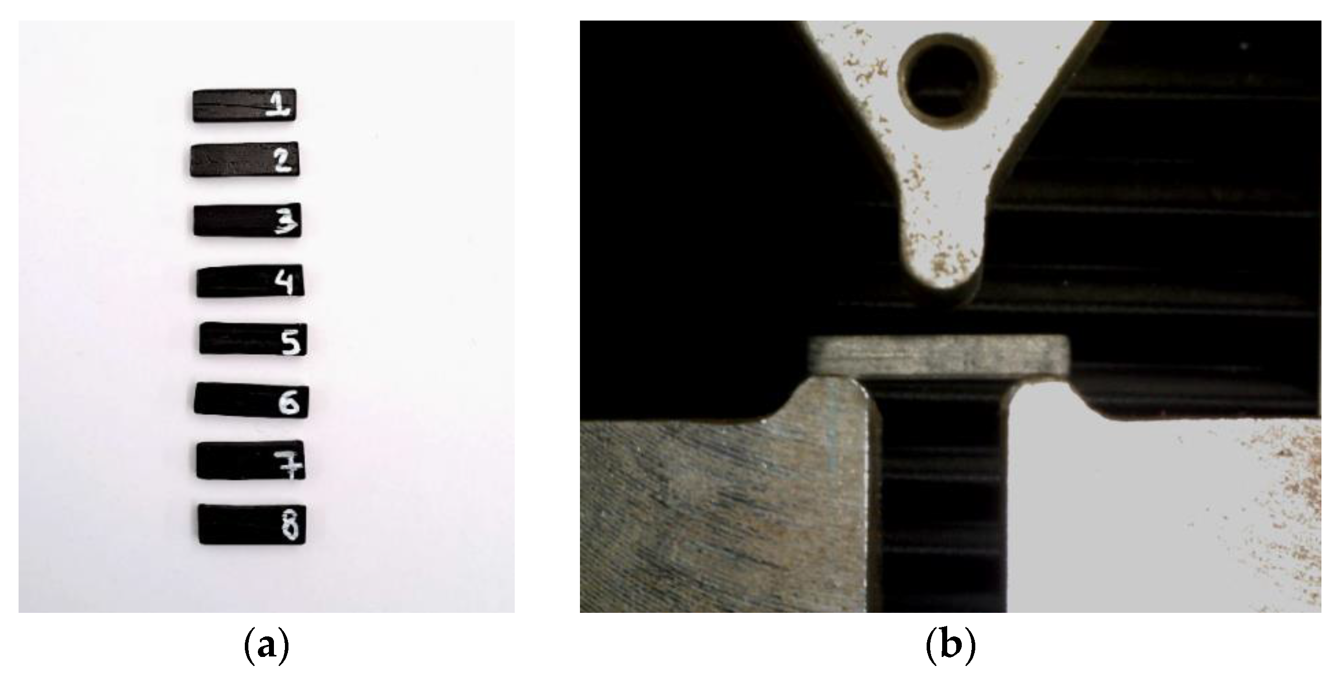
Figure 10.
C-scan images of tension specimens: (a) with vCFs; (b) with rCFs. The color bar indicates relative signal amplitude.
Figure 10.
C-scan images of tension specimens: (a) with vCFs; (b) with rCFs. The color bar indicates relative signal amplitude.
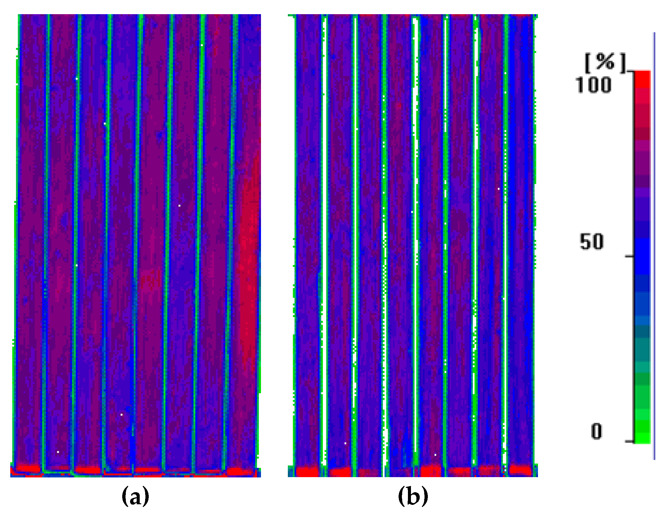
Figure 11.
C-scan images of compression specimens: (a) with vCFs; (b) with rCFs. The color bar indicates relative signal amplitude.
Figure 11.
C-scan images of compression specimens: (a) with vCFs; (b) with rCFs. The color bar indicates relative signal amplitude.
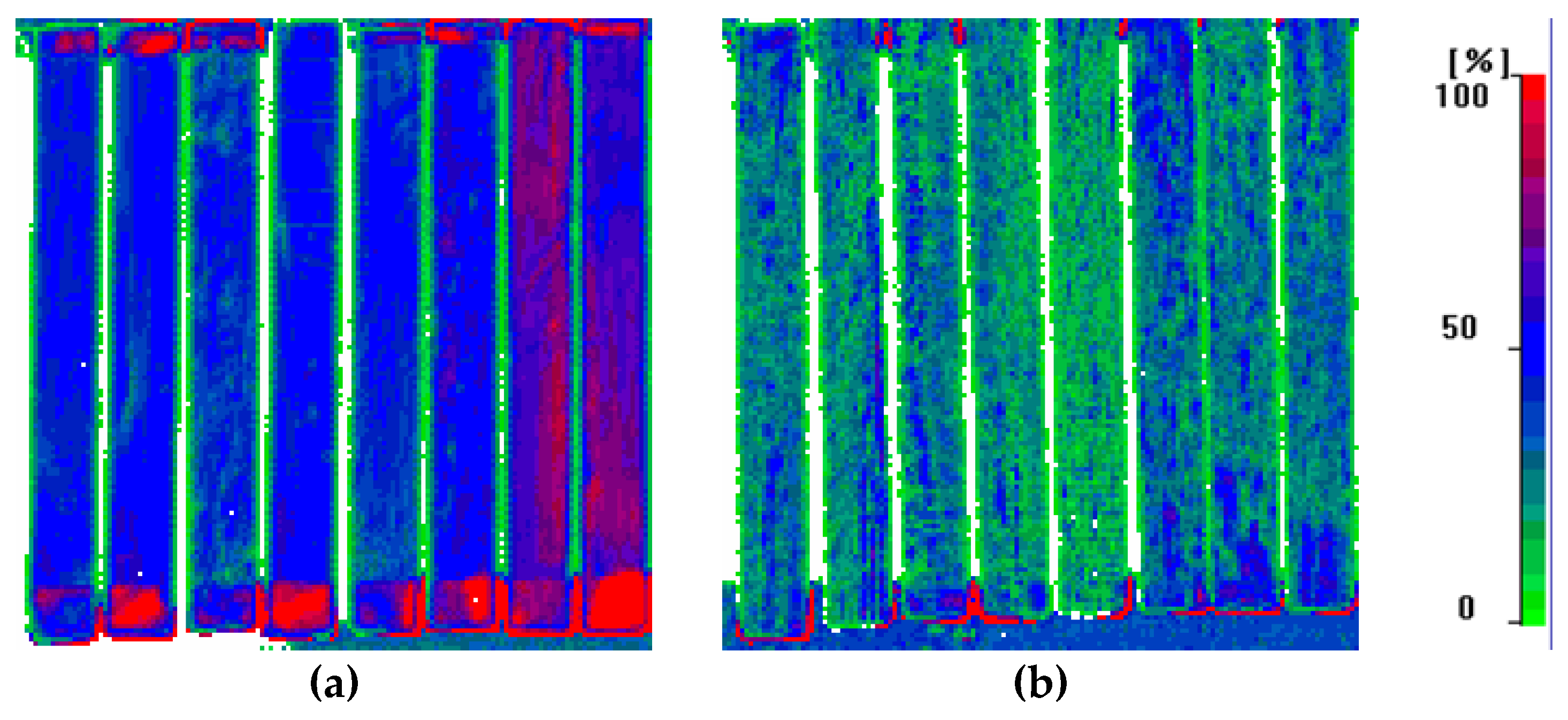
Figure 12.
Tensile stress–strain curves of CFRP coupons with virgin and recycled fibers.
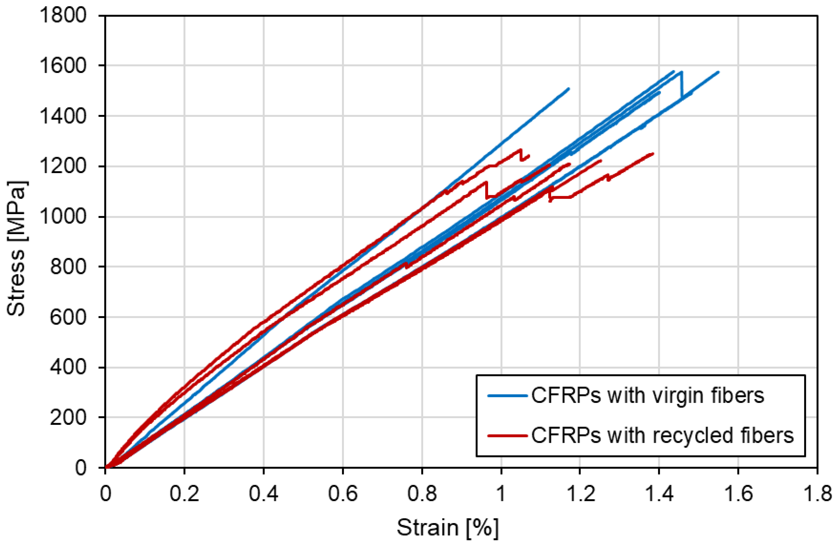
Figure 13.
Failed tension specimens: (a) virgin laminate; (b) recycled laminate.
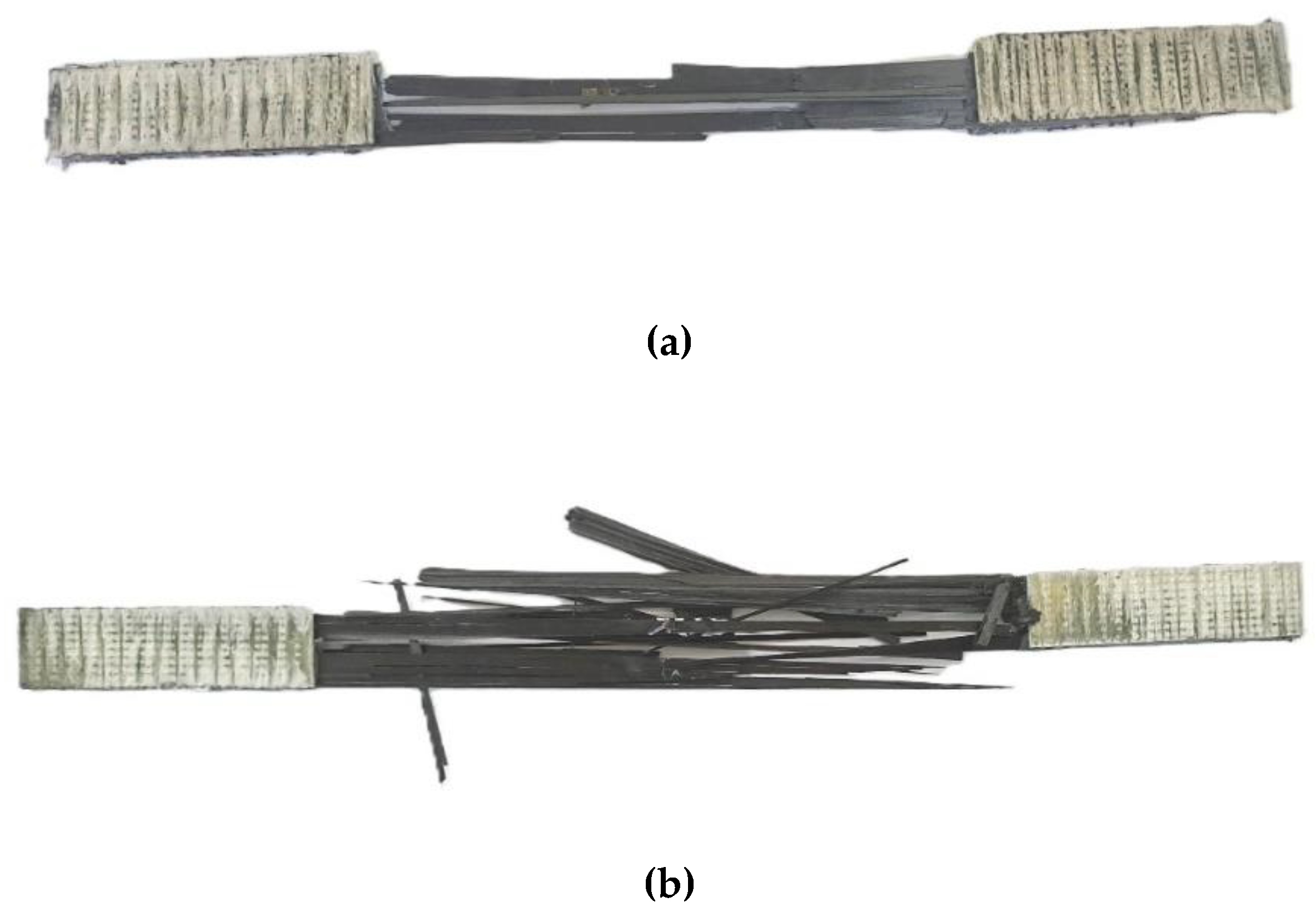
Figure 14.
Compressive stress–strain curves for all tested specimens: five virgin-fiber laminates and five recycled-fiber laminates.
Figure 14.
Compressive stress–strain curves for all tested specimens: five virgin-fiber laminates and five recycled-fiber laminates.
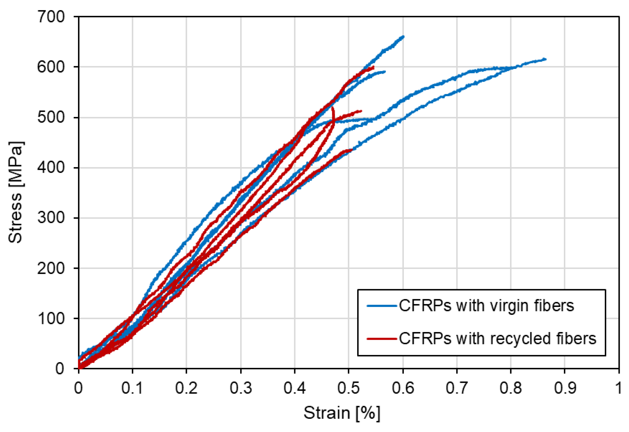
Figure 15.
Compression specimens after failure: (a) virgin laminate; (b) recycled laminate.
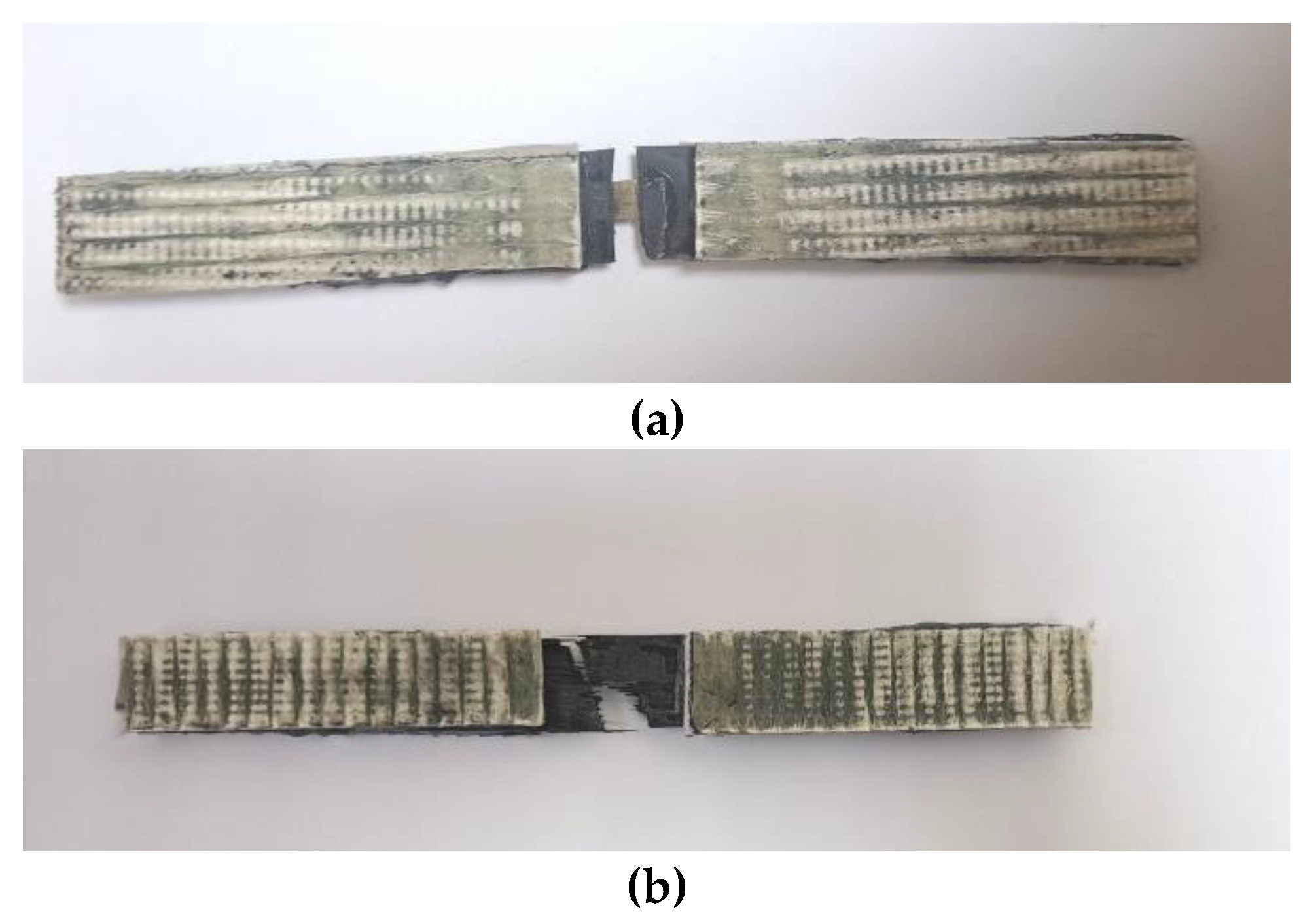
Figure 16.
ILSS force–displacement curves for all tested specimens: five virgin-fiber laminates and five recycled-fiber laminates.
Figure 16.
ILSS force–displacement curves for all tested specimens: five virgin-fiber laminates and five recycled-fiber laminates.
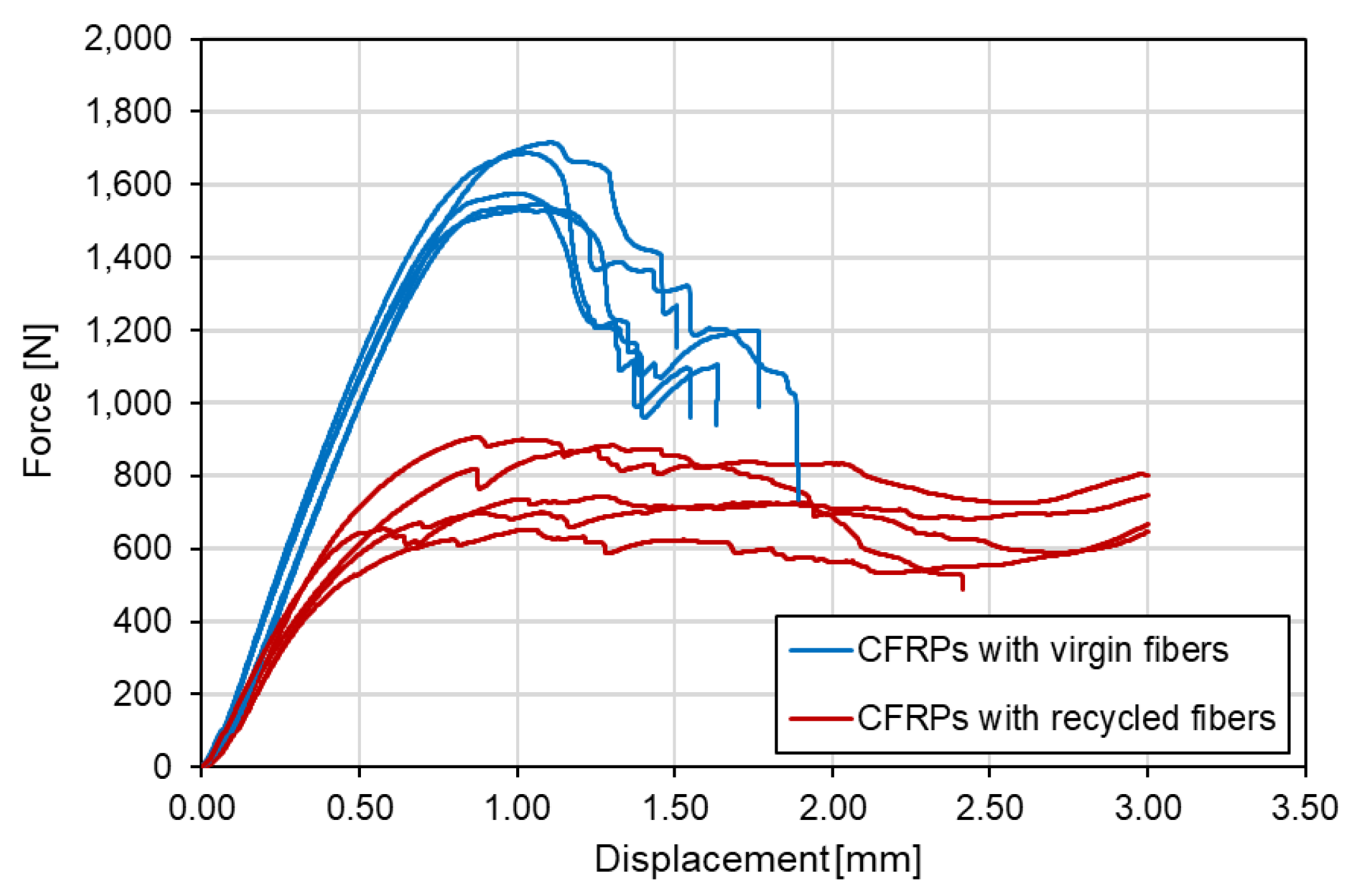
Figure 17.
Short-beam shear specimens after ILSS testing: (a) virgin laminate; (b) recycled laminate.
Figure 17.
Short-beam shear specimens after ILSS testing: (a) virgin laminate; (b) recycled laminate.
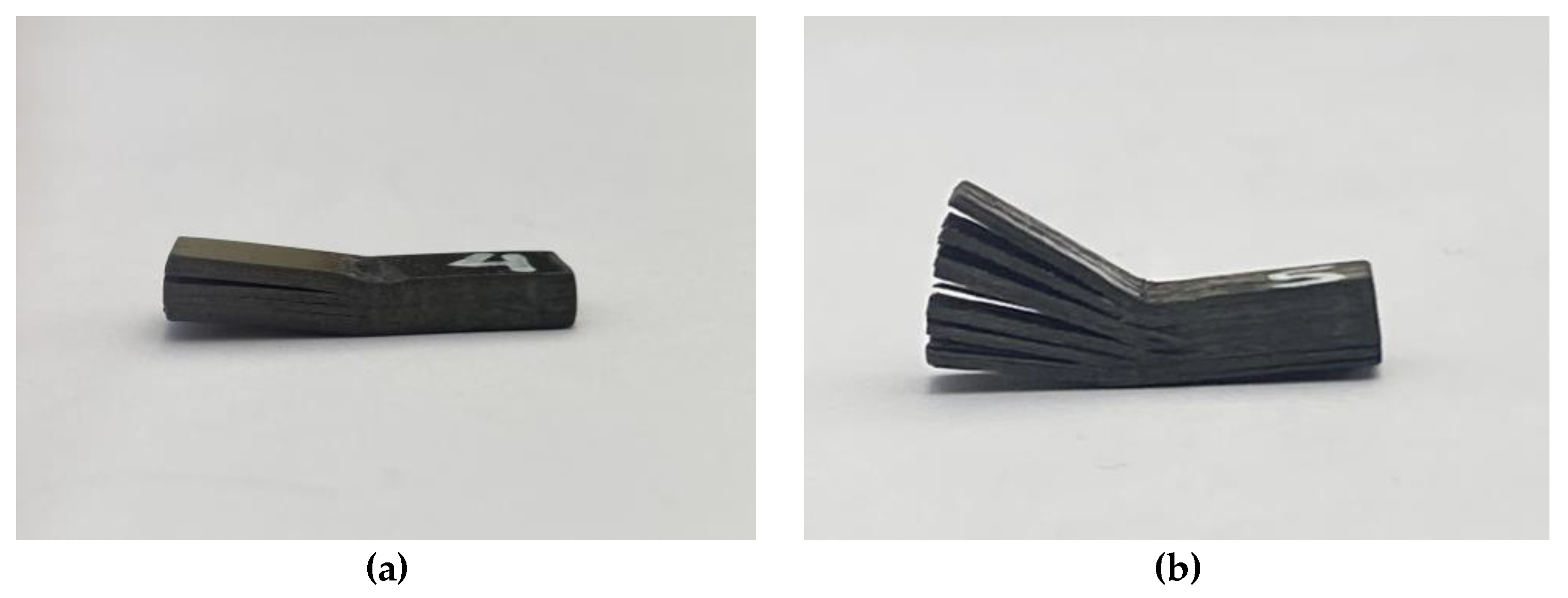

Table 1.
Average coupon dimensions (mean ± standard deviation, n = 5) for tension, compression, and ILSS tests.
Table 1.
Average coupon dimensions (mean ± standard deviation, n = 5) for tension, compression, and ILSS tests.
| Test Type | Fibers used | Thickness [mm] | Width [mm] | Length [mm] |
|---|---|---|---|---|
| Tension Test | vCFs | 1.10 ± 0.05 | 15.07 ± 0.28 | 251.60 ± 1.82 |
| rCFs | 1.12 ± 0.11 | 15.04 ± 0.33 | 250.00 ± 0.71 | |
| Compression Test | vCFs | 0.91 ± 0.09 | 15.41 ± 0.38 | 140.46 ± 0.97 |
| rCFs | 1.08 ± 0.03 | 14.36 ± 0.71 | 140.02 ± 0.62 | |
| ILSS Test | vCFs | 2.95 ± 0.12 | 6.17 ± 0.24 | 18.91 ± 0.01 |
| rCFs | 3.54 ± 0.08 | 5.91 ± 0.36 | 19.99 ± 0.03 |
Table 2.
Summary of mechanical properties of virgin and recycled CFRP laminates in tension, compression, and interlaminar shear.
Table 2.
Summary of mechanical properties of virgin and recycled CFRP laminates in tension, compression, and interlaminar shear.
| Property | Composites with vCFs | Composites with rCFs | Difference* [%] |
|---|---|---|---|
| Tensile strength (MPa) | 1538.55 ± 57.49 | 1236.43 ± 36.17 | -19.6 |
| Tensile modulus (GPa) | 175.07 ± 13.45 | 180.95 ± 18.24 | 3.4 |
| Ultimate tensile strain (%) | 1.42 ± 0.15 | 1.21 ± 0.11 | -14.8 |
| Compressive strength (MPa) | 593.48 ± 60.17 | 513.41 ± 58.92 | -13.5 |
| Compressive modulus (GPa) | 116.3 ± 17.44 | 108.39 ± 15.17 | -6.8 |
| Ultimate compressive strain (%) | 0.74 ± 0.13 | 0.67 ± 0.30 | -9.5 |
| Interlaminar shear strength (MPa) | 66.42 ± 1.88 | 28.07 ± 3.13 | -57.7 |
* Property of the CFRP laminate with rCFs minus the property of the laminate with vCFs, divided by the value for the laminate with vCFs, and multiplied by 100.
Disclaimer/Publisher’s Note: The statements, opinions and data contained in all publications are solely those of the individual author(s) and contributor(s) and not of MDPI and/or the editor(s). MDPI and/or the editor(s) disclaim responsibility for any injury to people or property resulting from any ideas, methods, instructions or products referred to in the content. |
© 2025 by the authors. Licensee MDPI, Basel, Switzerland. This article is an open access article distributed under the terms and conditions of the Creative Commons Attribution (CC BY) license (http://creativecommons.org/licenses/by/4.0/).
Copyright: This open access article is published under a Creative Commons CC BY 4.0 license, which permit the free download, distribution, and reuse, provided that the author and preprint are cited in any reuse.


