
Submitted:
10 December 2025
Posted:
11 December 2025
You are already at the latest version
Abstract
Reliable autonomy for drones operating in GNSS-intermittent or denied environments requires both stable inter-vehicle coordination and a shared global understanding of the environment. This paper presents a unified vision-based framework in which UAVs use biologically inspired swarm behaviors together with online monocular point-cloud registration to achieve real-time global localization. First, we apply a passive-perception strategy, bird-inspired drone swarm-keeping, enabling each UAV to estimate the relative motion and proximity of its neighbors using only monocular visual cues. This decentralized mechanism provides cohesive and collision-free group motion without GNSS, active ranging, or explicit communication. Second, we integrate this capability with a cooperative mapping pipeline in which one or more drones acting as global anchors generate a globally referenced monocular SLAM map. Vehicles lacking global positioning progressively align their locally generated point clouds to this shared global reference using an iterative registration strategy, allowing them to infer consistent global poses online. Other autonomous vehicles optionally contribute complementary viewpoints, but UAVs remain the core autonomous agents driving both mapping and coordination due to their privileged visual perspective. Experimental validation in simulation and indoor testbeds with drones demonstrates that the integrated system maintains swarm cohesion, improves spatial alignment by more than a factor of four over baseline monocular SLAM, and preserves reliable global localization throughout extended GNSS outages. The results highlight a scalable, lightweight, and vision-based approach to resilient UAV autonomy in tunnels, industrial environments, and other GNSS-challenged settings.
Keywords:
multi-robot systems
; cooperative localization
; point cloud registration
; visual SLAM
; GNSS intermittency
; aerial–ground collaboration
; resilient navigation
; online mapping
1. Introduction
Autonomous multi-drone systems are becoming increasingly essential for missions such as infrastructure inspection, subterranean exploration, search-and-rescue, and environmental monitoring. Many of these missions take place in GNSS-intermittent or fully GNSS-denied environments—including underground facilities, industrial interiors, collapsed structures, and dense urban corridors—where traditional satellite-based localization cannot be relied upon. In such conditions, UAVs must depend on onboard sensing, vision-based perception, and cooperative behaviors to sustain navigation performance, situational awareness, and team cohesion. Previous work has explored alternatives to GNSS, including image-to-map registration [1], terrain-constrained visual–DEM matching [2], and visual–geographical optimization [3], all of which underscore the growing need for robust localization strategies when absolute positioning is not available. To enable effective multi-UAV operations—potentially supported by ground robots but led by aerial agents—two complementary capabilities must be achieved simultaneously: spatial coherence, meaning a consistent and shared geometric understanding of the environment across UAVs, and coordination coherence, meaning stable, decentralized group behavior without continual access to global positioning or centralized control.
The achievement of spatial coherence is a major requirement for cooperative exploration and map fusion. Lightweight autonomous robots such as UAVs are constrained by payload, power, and cost, often relying primarily on monocular cameras. Although monocular visual SLAM (vSLAM) offers a feasible approach to local mapping, the resulting point clouds are inherently sparse and noisy. These inconsistencies complicate both map fusion and cooperative localization, particularly when comparing maps collected by aerial robots (with different viewpoints and altitudes) and other autonomous robots operating near the floor. To overcome these obstacles, robust map alignment demands specialized registration techniques capable of handling discrepancies in scale, density, viewpoint, and noise. Previous work has shown that coarse global feature matching—using learned matchers such as SuperGlue ([4]) or LoFTR ([5])—combined with fine-grained refinement methods such as point-to-plane ICP ([6]) significantly improves robustness. Global LiDAR-derived descriptors such as Scan Context ([7,8]) offer further insights into rotationally robust place recognition, although they are not directly applicable to sparse monocular maps. In our earlier work, [9] evaluated such pipelines for aligning monocular vSLAM point clouds from heterogeneous autonomous robots, demonstrating improved robustness to scale inconsistencies and viewpoint changes. This paradigm enables multiple drones to align their independently generated monocular maps into a shared global reference, allowing an autonomous robot with global pose information to serve as a proxy reference source for others.
At the same time, multi-drone autonomy also depends critically on coordination coherence—the ability of robots to maintain formation, avoid collisions, and modulate their spacing based solely on local sensing. This is especially challenging without explicit distance measurements, inter-robot communication, or GNSS. Biological swarms—such as flocks of starlings—provide a compelling inspiration. Decades of research show that natural swarms rely on topological, not metric, interaction rules: individuals react primarily to a small, fixed number of nearest neighbors, guided largely by passive visual cues ([10,11]). Early computational models such as the Boids framework ([12]) supported these findings. These principles inspired our previous work on the swarm control of UAVs ([13]), which demonstrated that monocular visual cues alone can provide sufficient passive information for UAVs to estimate relative proximity and adjust their trajectories using a decentralized Nonlinear Model Predictive Control (NMPC) strategy. That work showed that stable, cohesive group motion can be achieved without metric ranging, GNSS, or explicit inter-agent communication—mirroring the passive visual coordination found in natural swarms.
The synergy between these two research directions—vision-based cooperative localization (spatial coherence) and passive-vision swarm coordination (coordination coherence)—addresses a fundamental challenge in lightweight autonomous systems: how to achieve stable, team-level behavior when sensing is sparse, noisy, and ambiguous. Operating in GNSS-denied environments requires multi-drone teams not only to remain cohesive but also to share a consistent representation of the environment to coordinate exploration and maintain situational awareness. Cooperative SLAM research has explored related ideas through decentralized frameworks ([14]), map merging ([15]), collaborative occupancy mapping ([16]), distributed data fusion ([17]), and multi-agent visual–inertial odometry ([18]). However, these methods generally rely on richer sensing or higher communication bandwidth than what is available on UAVs. This work unifies our previously independent lines of research—cooperative visual point cloud registration ([9]) and passive-vision swarm-keeping ([13])—into a single integrated framework for drone-led multi-robot autonomy using only lightweight sensors and decentralized logic. By merging these concepts, we develop a real-time algorithm that enables different autonomous vehicles to maintain formation cohesion while simultaneously aligning their locally generated maps, even when GNSS is unavailable.
The key contributions of this journal article are therefore:
- A unified cooperative perception and coordination architecture integrating passive-vision, biologically inspired swarm-keeping with cross-platform monocular point cloud fusion.
- A real-time registration pipeline robust to sparse, drone-led heterogeneous monocular maps, enabling fast alignment between different autonomous vehicles’ vSLAM maps during motion.
- Integrated experimental validation in an indoor GNSS-denied testbed, demonstrating stable formation keeping from passive vision, global map alignment improving spatial coherence, and real-time cooperative localization under extended GNSS outages.
By merging biologically inspired visual coordination with robust cooperative perception and online registration, this work provides a scalable, lightweight, and resilient strategy for drone-led heterogeneous teams or autonomous vehicles operating in GNSS-intermittent or denied environments, supporting practical applications such as underground inspection, industrial automation, and disaster response.
2. Materials and Methods
This section describes the system architecture, sensing modalities, swarm coordination logic, visual SLAM pipeline, and the online point cloud registration framework used to achieve cooperative global localization under GNSS-intermittent or denied conditions. The methodology integrates biologically inspired passive-vision-based coordination with lightweight cooperative perception among autonomous vehicles.
2.1. Swarm Coordination Using Passive Vision
The aerial swarm uses a bio-inspired topological coordination rule, derived from flocking behavior in birds, where each agent adjusts its trajectory based on the apparent motion and angular size of neighboring agents. The study in [19] was the first to capture the internal 3D structure of flocking birds, revealing a formation pattern among nearest neighbors based on angular distribution. Later, [10] reconstructed a 3D swarm of thousands of birds and demonstrated that local interactions depend on topological distance rather than metric distance. Birds consistently interact with a fixed number of nearest neighbors, maintaining cohesive formations even as global density varies.
The proposed swarming model draws inspiration from biological behavior, emphasizing the absence of explicit distance measurement between agents, referred to as metric distance in [10]. Its core principle is that agents—especially those within the swarm’s interior—instinctively adjust their positions to maintain approximately equal spacing from their closest neighbors. This is particularly relevant in large swarms, where interior agents face sensory limitations, such as obstructed vision, preventing them from assuming alternative roles like temporary leadership. Since biological agents cannot measure exact distances, it is reasonable to assume they rely on an innate sense of proximity, using relative cues to position themselves centrally within the group. In its simplest form, this mechanism assumes agents share similar attributes, such as size, enabling them to estimate closeness through perceived size differences. However, size alone is insufficient for cohesion. Therefore, the model hypothesizes that a biologically determined optimal spacing, combined with a common speed, forms universal principles governing swarm behavior [10]. Ultimately, the model rests on the notion that agents, particularly those in central positions, instinctively regulate their spacing to maintain uniformity—a behavior that becomes critical in large swarms where sensory constraints limit alternative strategies.
According to [13,20], the surrounding space of each agent is partitioned into adjacent zones based on its position, direction of motion, and the horizontal plane, as illustrated in Figure 1. In total, twelve lateral sectors are defined—six above and six below the horizontal plane—along with two forward-facing sectors and one blind sector oriented backward. All sectors extend up to a maximum radius . The upper lateral space is divided into six angular ranges: , , , , , and determined by the vertical angle The lower lateral sectors mirror these divisions using . Two forward sectors are defined as with a larger extension to compensate for the larger relative velocity, while the blind sector, based on avian physiology, spans . The number, thickness, and maximum radius of these sectors should be selected according to swarm dynamics and individual agent behavior, and can be fine-tuned through extensive simulations before flight testing. As detailed later, the relative proximity of neighboring agents is assessed using opposing sectors. This approach evaluates perceived distances and angles by comparing relative closeness, similar to how animals sense neighbors in large aggregations. When applied to unmanned aerial vehicles, behaviors such as cohesion, separation, and alignment emerge through an auto-centering mechanism rather than explicit distance calculations. Unlike models that rely on precise measurements, this method reproduces bird-like aggregation patterns using relative perception of proximity rather than metric distances.
The proposed swarming model, inspired by biological systems, operates without explicit measurement of inter-agent distances (metric distances). Instead, it assumes that agents instinctively strive to maintain approximately equal spacing from their nearest neighbors. This behavior is particularly critical for agents located within the interior of large swarms, where vision and sensing capabilities are often limited. Since biological organisms cannot measure exact distances, they likely rely on relative proximity cues to maintain their position within the group. Assuming agents share similar characteristics—such as size—they can estimate closeness by comparing perceived size differences. However, this mechanism alone is insufficient for maintaining cohesion. The model therefore incorporates the concept of a biologically preferred spacing (preferred distance ) and a common speed , which are assumed to be universal among swarm members. Birds, for instance, exhibit limited depth perception due to restricted binocular vision, where each eye captures slightly different perspectives without enabling precise distance estimation ([21]). These limitations suggest that flocking behavior is unlikely to depend on exact distance measurements. The method for estimating relative distances from passive visual cues is detailed in the following subsection. Each agent updates its neighbor selection and speed adjustment (speed correction ) at every time step using data obtained from onboard cameras monitoring its surroundings:
Neighbor Selection:
- Identify the closest neighbors within each lateral sector.
- Compare relative proximity between opposing lateral sectors (e.g., upper versus lower .
- Select the closest neighbors in the forward sectors.
- Compare the relative proximity of forward neighbors to a predefined forward preferred distance (based on the expected relative speed in the forward direction).
- If any opposing lateral sector pair contains only one neighbor, apply a similar logic using a lateral preferred distance .
Speed Correction:
- For opposing lateral sectors containing neighbors in both, generate a speed correction toward the center of the sector with the more distant neighbor. The correction magnitude is fixed and determined through simulation. If relative sizes (proxy for distance) are similar, no correction is applied.
- For opposing lateral sectors with only one neighbor, assume a neighbor exists at the preferred lateral distance and apply the same correction logic.
- Apply the same approach for forward sectors using the preferred forward distance .
- If no neighbors exist in either lateral or forward sectors, no correction is generated.
- Sum all corrections and adjust the commanded speed accordingly.
2.1.1. Passive Distance or Depth Estimation
Each agent uses its onboard monocular camera to detect neighboring agents. Crucially, the system does not require explicit distance sensors or unique neighbor identification. The relative distance between agents is estimated solely from the apparent pixel size of the agent in each other’s image plane, leveraging the known physical size of the UAVs.
Our approach guides individual corrective actions within a collective system of vehicles by applying a logic centered on proximity rather than precise distance measurements. Instead of relying on exact metric calculations, as discussed in [10] and related studies, the method uses perceived closeness to adjust each agent’s speed and position. By estimating relative distance, agents reposition themselves toward the center of their local neighborhood, gradually reducing disparities between opposing agents. This process promotes uniform swarm speed and cohesive movement patterns. The resulting spatial reasoning fosters synchronized motion and structured group cohesion, enabling autonomous and harmonious collective behavior without centralized control.
Distance estimation from visual data can be achieved through various techniques. Depending on computational resources, these range from advanced artificial intelligence methods—such as the deep learning approach proposed in [22], which employs neural networks for distance prediction—to simpler image-processing strategies like those in [23]. These techniques may use multiple cameras or a single one. Our work adopts the latter, bio-inspired approach, reflecting how birds in flocks typically rely on monocular vision and infer distance from relative size cues. Given the limited onboard processing capabilities of drones, we employ a lightweight algorithm that extracts numerical data from pixel color variations. Bird flocks exemplify how simple local rules can yield effective collective behavior despite restricted sensing abilities. Coordination emerges without a central leader, enabling optimized group structure, obstacle avoidance, and complex maneuvers under natural constraints.
A key assumption in this method is that all agents share similar size and physical characteristics—comparable to members of the same species. This commonality allows each agent to effectively compare the relative sizes of its closest neighbors across adjacent sectors, supporting accurate proximity estimation.
The estimation of inter-agent distance from 2D imagery is performed here using a pixel-based detection method that relies on a prior metric calibration of the target object’s size. This approach assumes a pre-existing relationship between the object’s real-world dimensions and its pixel representation in the image. This assumption is biologically plausible, drawing inspiration from bird swarm behavior, where neighbor proximity may be inferred through passive visual cues such as perceived size. We acknowledge that biological systems might leverage additional sensory inputs (e.g., acoustics or olfaction) to refine proximity estimates, but these are not integrated into the current model.
Several methods exist for estimating distances from 2D imagery. In this work, distance is inferred from pixel measurements obtained from a single monocular camera, based on a pre-calibrated relationship between object size in pixels and metric distance. This assumption is realistic: biological systems—such as birds—are believed to encode approximate size, shape, or color cues about their conspecifics, either through learning or innate mechanisms. Although real animals may also rely on acoustic or olfactory cues, the present work focuses exclusively on visual information.
To isolate the drone’s visual markers, each pixel value represented by a byte in the range of is compared against an empirically determined intensity , producing a binary image with values in . This step separates potential markers from the background. Threshold selection involves stochastic considerations, including camera noise and variations in lighting.
The final stage is the logical processing of the binary data to extract a reliable distance estimate. In this implementation, the two lights on the drone are treated as fixed reference points of known relative geometry. The processing pipeline includes:
- Detect all connected components in the binary image and compute their centroids and pixel areas; discard components with areas outside a predefined valid range.
- Compute pairwise distances between remaining centroids and retain the pair with the smallest separation and with an orientation angle within an acceptable range.
- Associate the selected centroids with those from the previous frame using nearest-neighbor matching to maintain unique marker identities, and calculate their inter-distance .
- Repeat the process for each incoming frame, with no need for external initialization.
This algorithm is designed to be self-recovering: if detection fails temporarily due to occlusion or noise, the system automatically re-acquires the markers in subsequent frames. The output is the distance in pixels between the two valid markers .
2.2. VSLAM Theory
This section reviews the theoretical foundation for cooperative visual localization using monocular Visual Simultaneous Localization and Mapping. Our approach involves two independently generated point clouds: a referenced global map obtained from a first drone that simultaneously estimates its position using global positioning information, and a second locally referenced map captured by another vehicle from the same scene. The core objective is to register the local point cloud to the global one using alignment techniques [24]. This process effectively globally references the second map, enabling the second robot to obtain global localization without requiring explicit (from a global positioning system) knowledge of its own position.
Each agent operates a lightweight monocular vSLAM pipeline designed to estimate its motion and map the environment using a single camera. This pipeline outputs a local camera trajectory, a sparse monocular point cloud, and a set of keyframes enriched with detected features. The process begins with feature extraction and matching, followed by motion estimation for robust pose computation. To refine accuracy, local bundle adjustment optimizes both camera poses and 3D points, while keyframe insertion and local map generation maintain a consistent representation of the scene.
2.2.1. Monocular VSLAM
Monocular vSLAM recursively performs two tightly coupled tasks: (1) Map Construction, which generates a 3D representation (point cloud) of the environment from sequential image features, and (2) Localization, which estimates the camera’s 6-DOF pose by localizing it within the evolving map. This recursive process leverages principles derived from stereo vision, specifically requiring the estimation of the camera’s relative pose (translation and rotation) between consecutive image frames.
2.2.2. Stereo Calibration and Image Rectification
The vSLAM process simulates a stereo vision setup by treating two consecutive, initially uncalibrated frames from a single moving camera as a pair of spatially separated cameras. In a standard calibrated stereo scenario, the two cameras are perfectly aligned with translation only along a horizontal baseline b. This configuration significantly simplifies the Correspondence Problem (finding the 3D location of an object seen in both images) by allowing the direct estimation of the 3D position from matched pixel coordinates:
where and are the camera intrinsic parameters, and and are the pixel coordinates of the object in the left and right images, respectively.
When the camera undergoes arbitrary motion, the simple stereo condition is lost, and the images must be rectified [25]. Image rectification transforms the views such that corresponding points lie on the same horizontal line (sharing the same vertical coordinate v). This transformation is based on the principles of Epipolar Geometry [26] and reduces the correspondence search from a two-dimensional space to a one-dimensional search along a common line, thereby recovering the simple stereo configuration. The initial steps for generating candidate 3D points from rectified image pairs are as follows:
- Image Distortion Correction: Radial distortion is corrected using the camera’s intrinsic calibration matrix , obtained through camera intrinsic calibration [23]:
- Feature Matching: The detected features are matched between the two images by comparing their descriptors (e.g., via Hamming distance).
2.2.3. Pose Calculation
The Essential matrix or Fundamental matrix encodes the relative pose of the camera between the two frames, yielding the translation vector and the rotation matrix , which form the basis of the localization trajectory. Given a set of matching points between the two key frames (a subset of images with significant changes), the matrices are estimated by solving the Epipolar equation, represented as:
or using normalized coordinates:
Once the Essential matrix is determined, the relative camera pose is uniquely defined by the relationship:
This constraint enables the recovery of the relative translation and rotation through singular value decomposition. By chaining these estimated pose transformations across frames, the VSLAM system constructs the full 3D camera trajectory, completing the localization component.
2.3. Online Cooperative Point Cloud Registration
The process of fusing the two independently generated 3D maps begins once both are constructed. The first map, generated by the first vehicle, serves as the target point cloud and is reliably referenced through an external global navigation System. Conversely, the second map, captured by the second autonomous vehicle, constitutes the source point cloud and is inherently lacking global positional information. The central objective of this pipeline is to globally reference the second’s map by estimating the optimal rigid transformation necessary to align the source cloud with the first vehicle’s globally referenced target map.
The core alignment technique utilized is the Iterative Closest Point (ICP) algorithm, a standard method for determining the rigid transformation (rotation and translation) that best aligns a source point cloud to a target point cloud. This alignment is achieved by iteratively finding and minimizing the distance between corresponding points. The standard ICP pipeline involves the following steps:
- Initial Alignment: Begin with an initial transformation guess, often the identity matrix or a prior estimate from a coarse alignment method.
- Closest Point Matching: For each point in the source cloud, identify its nearest neighbor (the closest point) in the target cloud.
- Transformation Estimation: Compute the rigid transformation that minimizes the mean squared error (MSE) between the established matched point pairs.
- Apply Transformation: Update the source point cloud’s position and orientation using the estimated transformation.
- Iteration: Repeat steps 2 through 4 until convergence, defined by a minimal reduction in the MSE or reaching a maximum iteration limit.
To enhance the robustness and improve the convergence rate—especially when dealing with sparse, noisy maps typical of monocular VSLAM—specialized ICP variants are employed [30]: (i) Point-to-plane ICP minimizes the distance from a source point to the tangent plane defined by its corresponding closest point and the estimated surface normal in the target cloud. This approach effectively leverages local surface geometry for improved alignment compared to the standard point-to-point metric, particularly in environments with distinct planar features. (ii) Plane-to-plane ICP further generalizes this concept by incorporating planar approximations from both the source and target clouds. This method minimizes the misalignment between corresponding local surface patches.
Given a fixed target point cloud , and a pair-wise matched moving source point cloud , for , point-to-point ICP estimates the 3D rigid transformation by minimizing the sum of squared distances between these corresponding matched points:
3. Results
This Section presents the simulated as well as experimental validation of the proposed framework, which combines passive-vision swarm coordination and online cooperative point cloud registration under global localization intermittency. Experiments were conducted in a controlled indoor environment using a drone-led team of autonomous vehicles, each equipped with onboard cameras. All simulations or experiments were designed to: (1) demonstrate stable biological-inspired swarm cohesion using only monocular imagery; and (2) evaluate online map alignment between platforms under heterogeneous viewpoints and sensor constraints.
The proof of concept for this cooperative perception framework was validated indoors using a heterogeneous team of three autonomous vehicles: two Crazyflie 2.1+ unmanned aerial vehicles ([31] and a Wifibot Lab V4 ground vehicle ([32]), all equipped with monocular RGB cameras. These drones were selected for their lightweight design and agility, making them well-suited for constrained indoor environments. The Wifibot Lab V4, a four-wheel-drive mobile platform, provided ground-based sensing and mobility.
3.1. Swarm-Keeping Performance
This Section tests the swarm keeping logic using visual information during hover.
3.1.1. Simulation Test
This Section tests the bio-inspired swarm keeping logic for three simulated drones, with sectors defined by , preferred distance , preferred forward distance , vertical angle , speed correction , and general velocity . Each drone starts at a random 3D position, and using the bio-inspired logic, each one adjusts its velocity to a new stable hover position. Figure 2 shows the final 3D position and their locations in their neighbors’ sectors, as well as their interdistances (blue: drones 1-2, red: drones 1-3, orange: drones 2-3), and speed changes, heavily influenced by the preferred distances. For this run, drones 2 and 3 maneuvered, while drone 1 remained in its original position.
To test the swarm stability and cohesive interaction in steady state conditions, 100 runs were conducted for different initial conditions. Figure 3 shows the interdistances between pairs of drones compared to their final steady state separation. The upper graph shows the three interdistances for each run (300 curves) as they settle to their steady state values. The lower graph shows the sample mean and variance of these curves as a function of time, confirming a smooth convergence to a stable formation.
3.1.2. Flight Test
Flight tests were conducted to test the passive topological coordination. All bio-inspired parameters used are similar to previous simulation. One maintained hover while the other maneuvered to keep a specified distance from the first, remain centered in its image, corresponding to the forward sectors defined by , and stay at the same fixed height. Figure 4 shows a single-color scale image selected from the video (left), and a 3D sketching of each pixel’s intensity (right). It can be seen that the two lights are clearly distinguishable from the rest of the image. The two markers are extracted by threshold comparison. After iterative prior testing across multiple videos, a threshold of approximately was selected.
The control strategy allows the second quadrotor to dynamically adjust its position relative to the hovering one using visual cues. The drone firmware utilizes a cascaded PID control structure across multiple levels—position, velocity, attitude, and attitude rate. The specific controllers engaged depend on the setpoint provided to the system, in this case, horizontal commanded velocities . In every control mode, the angle-rate controller translates the desired angular rates into PWM signals for the motors. A detailed illustration of this inner control architecture is available in [31].
Guidance was achieved using two proportional controllers based on visual feedback: the distance error in pixels (longitudinal location), , and the lateral error in pixels, . The quantity u corresponds to the horizontal component in pixels of the geometric center of both markers. These quantities are converted into commanded across and along velocities, computed as , and , respectively. For this test , and corresponding to the horizontal center of the camera. Then these velocities were fed into the inner controllers. Both raw measurements and were smoothed by a low-pass filter, given and . Figure 5 shows commanded, measured, and filters quantities.
3.2. Online Point Cloud Registration
The proof of concept for the cooperative perception framework was evaluated indoors with two different configurations: 1) using two aerial drones, and 2) using one ground vehicle and one drone.
3.2.1. First Configuration: Two Drones
The first drone follows a predefined trajectory while capturing video. This path is designed to cover a broader area, generating a point cloud that is larger and encompasses the point cloud to be produced by the second drone. In contrast, the second drone hovers in place while recording its frames, with its pose slightly offset to the flight path of the first drone. The objective is to assess the registration of two point clouds of different sizes, captured from distinct perspectives, where one is geometrically a subset of the other.
Each drone video consisted of 400 images at a resolution of pixels, with camera intrinsics previously calibrated as follows:
Feature extraction and matching constitute essential components of the monocular vSLAM pipeline. Feature extraction identifies the salient image points and generates descriptors representing the local neighborhood of pixels. Matching then pairs descriptors across consecutive key frames by comparing these feature vectors using similarity metrics such as Hamming or Euclidean distance. These correspondences support pose estimation, image alignment, and dense 3D reconstruction. For example, Figure 6 illustrates the features detected in two consecutive drone key images and the established matches.
The alignment of the second point cloud (smaller in size) with respect to the first one (larger) was done using the ICP algorithm. The obtained rigid transformation matrix is given by:
from where the rotation matrix can be seen to closely resemble the identity matrix (given a small orientation misalignment), and the translation to be mainly along the y-axis. Figure 7 shows the trajectories and point clouds of both drones. It can be observed that the point cloud of the second drone is a subset of the first point cloud, exhibiting some differences, primarily in height and orientation. Two different perspectives are presented.
Figure 8 shows the scene in front of the drones (up), and the point cloud reconstructed by overlapping the one from the first drone and the one realigned from the second drone. It can be seen that they complement each other.
The registration can also be performed in real time as the second drone’s scene is being processed. In this case, the first drone generates a broader point cloud, which is then available for the second drone to register against its own point cloud as it is being created. Figure 9 shows the orientation and translation of the second point cloud during its processing and registration with the first one. It is interesting to note how the pose of the second point cloud gradually stabilizes to fixed values as more key frames are used .
3.2.2. Second Configuration: One Ground Vehicle and One Drone
Both robots navigated autonomously through the laboratory while capturing visual data of the shared environment. Each platform carried an onboard monocular camera for local vSLAM processing and also had access to an external motion-capture–based positioning system for ground-truth evaluation. This external system consisted of a ceiling-mounted camera array connected to a laboratory computer that tracked each robot’s position and heading in real time.
The experimental procedure was structured as follows. The ground vehicle first executed a predefined trajectory while recording video of its surroundings. This video was processed to generate a monocular point cloud and an associated trajectory, both referenced to the camera’s initial orientation—the natural reference frame used by monocular vSLAM. Using the external positioning system, this point cloud and trajectory were then transformed into the laboratory’s global coordinate frame, producing a referenced baseline map.
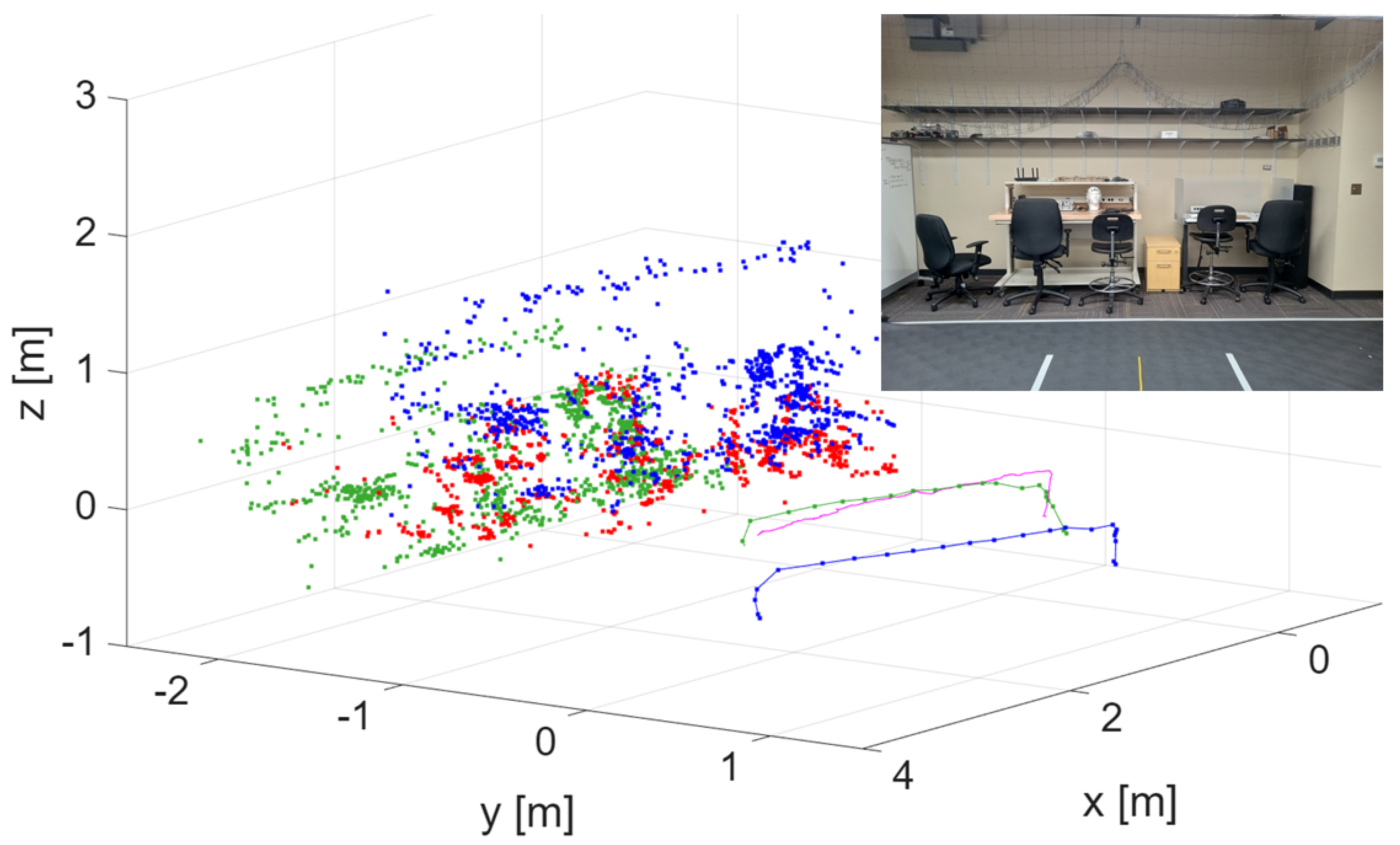
The drone followed a similar procedure, capturing its own video and generating a local point cloud. Unlike the ground vehicle, the drone did not use external positioning for navigation. Instead, it aligned its local point cloud with the globally referenced ground-vehicle point cloud, thereby correcting its pose and obtaining a globally referenced trajectory through cooperative point cloud registration. The externally measured drone position was used solely to evaluate the accuracy of this approach. The core objective of the experiment was to obtain a globally consistent trajectory for a robot operating without global positioning by registering its map to a previously globally referenced map of the environment. Importantly, the roles of the two autonomous vehicles are interchangeable and may be reversed in other scenarios.
Because the ground vehicle serves as the reference robot, its point cloud is used to globally reference the drone’s point cloud later in the experiment. For consistency, we assume that the laboratory scene remains unchanged between the times at which the two videos (car and drone) are recorded. The camera, rigidly mounted to the vehicle, is oriented 90 degrees to the right relative to the vehicle’s forward motion, ensuring that both robots observe the same region of the lab.
The ground vehicle’s video and synchronized position measurements were processed to generate a vSLAM-based point cloud referenced to the laboratory coordinate system, with an acquired dataset consisting of 388 grayscale images at a resolution of pixels. The camera intrinsics of the car are given by
The drone mostly traversed the same region as the ground vehicle, capturing a video of the environment using its onboard monocular camera. Its flight path consisted of a vertical takeoff to approximately 0.5 meters, a horizontal translation following a straight-line motion similar to the ground vehicle’s trajectory, and a final vertical descent for landing. The drone’s map and trajectory were aligned with the ground vehicle’s globally referenced map, giving the 3D rigid transformation matrix:
Figure 10 presents the point clouds of the drone before and after realignment, as well as the ground vehicle’s point cloud. It also includes the drone’s trajectories (initial, after registration, and true). The corrected trajectory is closer to the true one (obtained by using the Lab positioning system), showing an error reduction of around 4:1. The shared scene is also shown in the inset.
4. Conclusions
This work introduced an integrated framework that combines bio-inspired passive-vision swarm coordination with cooperative monocular point-cloud registration to achieve resilient multi-robot localization in GNSS-denied environments. Using only lightweight onboard cameras, the method enables a drone and ground robot to maintain coordinated motion while simultaneously building and aligning local maps.
The passive-vision coordination strategy, motivated by biological swarms, allowed the drones to maintain stable inter-agent spacing without external positioning information, explicit ranging sensors, or centralized control. In parallel, the cooperative perception module aligned sparsely reconstructed monocular point clouds through a registration pipeline, allowing non-GNSS agents to recover a globally referenced trajectory. Indoor experiments demonstrated that the proposed alignment improves spatial consistency.
Results from drone-led teams trials confirm that the combined behavioral and geometric approach is feasible under realistic constraints, including limited onboard computational power, viewpoint variability, and partial occlusions. By maintaining both coordination coherence and spatial coherence, the framework offers a practical solution for multi-robot operation in tunnels, metro environments, industrial interiors, and other GNSS-intermittent settings.
Future work will scale the approach to larger teams, investigate more robust feature-sharing strategies, and integrate semantic or learning-based components to further strengthen resilience under communication loss and complex environments.
Supplementary Materials
The following supporting information can be downloaded at the website of this paper posted on Preprints.org.
Author Contributions
Conceptualization, Gonzalo Garcia and Azim Eskandarian; Methodology, Gonzalo Garcia; Software, Gonzalo Garcia; Validation, Gonzalo Garcia and Azim Eskandarian; Formal analysis, Gonzalo Garcia and Azim Eskandarian; Investigation, Gonzalo Garcia; Resources, Gonzalo Garcia and Azim Eskandarian; Writing—original draft, Gonzalo Garcia; Writing—review & editing, Azim Eskandarian; Visualization, Azim Eskandarian; Supervision, Azim Eskandarian; Project administration, Azim Eskandarian.
Data Availability Statement
The original contributions presented in this study are included in the article/Supplementary Material. Further inquiries can be directed to the corresponding author(s).
Conflicts of Interest
The authors declare no conflicts of interest.
References
- Lee, I.; Sung, C.; Lee, H.; Nam, S.; Oh, J.; Lee, K.; Park, C. Georeferenced UAV Localization in Mountainous Terrain Under GNSS-Denied Conditions. Drones Published. 2025, 9, 709. [Google Scholar] [CrossRef]
- Yao, F.; Lan, C.; Wang, L.; Wan, H.; Gao, T.; Wei, Z. GNSS-denied geolocalization of UAVs using terrain-weighted constraint optimization. International Journal of Applied Earth Observation and Geoinformation 2024, 135, 104277. [Google Scholar] [CrossRef]
- Xu, W.; Yang, D.; Liu, J.; Li, Y.; Zhou, M. A Visual Navigation Algorithm for UAV Based on Visual-Geography Optimization. Drones 2024, 8, 313. [Google Scholar] [CrossRef]
- Sarlin, P.E.; DeTone, D.; Malisiewicz, T.; Rabinovich, A. SuperGlue: Learning Feature Matching with Graph Neural Networks. In Proceedings of the Proceedings of the IEEE/CVF Conference on Computer Vision and Pattern Recognition (CVPR), 2020; pp. 4938–4947. [Google Scholar] [CrossRef]
- Sun, J.; Shen, Z.; Wang, Y.; Bao, H.; Zhou, X. LoFTR: Detector-Free Local Feature Matching with Transformers. In Proceedings of the Proceedings of the IEEE/CVF Conference on Computer Vision and Pattern Recognition (CVPR), 2021; pp. 8922–8931. [Google Scholar] [CrossRef]
- Besl, P.J.; McKay, N.D. A Method for Registration of 3-D Shapes. IEEE Transactions on Pattern Analysis and Machine Intelligence 1992, 14, 239–256. [Google Scholar] [CrossRef]
- Kim, G.; Kim, A. Scan Context: Egocentric Spatial Descriptor for Place Recognition Within 3D Point Cloud Map. In Proceedings of the 2018 IEEE/RSJ International Conference on Intelligent Robots and Systems (IROS), 2018; pp. 4802–4809. [Google Scholar] [CrossRef]
- Kim, G.; Choi, S.; Kim, A. Scan Context++: Structural Place Recognition Robust to Rotation and Lateral Variations in Urban Environments. IEEE Transactions on Robotics 2021, 38, 1856–1874. [Google Scholar] [CrossRef]
- Garcia, G.; Eskandarian, A. Point Cloud Registration for Visual Geo-referenced Localization between Aerial and Ground Robots. In Proceedings of the Proceedings of the 22nd International Conference on Informatics in Control, Automation and Robotics, Marbella, Spain, October 2025; Vol. 2, pp. 211–218. [Google Scholar]
- Ballerini, M.; Cabibbo, N.; Candelier, R.; Cavagna, A.; Cisbani, E.; Giardina, I.; Lecomte, V.; Orlandi, A.; Parisi, G.; Procaccini, A.; et al. Interaction ruling animal collective behavior depends on topological rather than metric distance: Evidence from a field study. Proceedings of the National Academy of Sciences of the United States of America 2008, 105, 1232–1237. [Google Scholar] [CrossRef] [PubMed]
- Cavagna, A.; Cimarelli, A.; Giardina, I.; Parisi, G.; Santagati, R.; Stefanini, F.; Viale, M. Scale-free correlations in starling flocks. Proceedings of the National Academy of Sciences 2010, 107, 11865–11870. [Google Scholar] [CrossRef] [PubMed]
- Reynolds, C.W. Flocks, herds, and schools: a distributed behavioral model. Computer Graphics 1987, 21, 25–34. [Google Scholar] [CrossRef]
- Garcia, G.; Eskandarian, A. Bio-Inspired UAS Swarm-Keeping based on Computer Vision. In Proceedings of the 2024 International Conference on Unmanned Aircraft Systems (ICUAS), 2024. [Google Scholar]
- Cieslewski, T.; Choudhary, S.; Scaramuzza, D. Data-Efficient Decentralized Visual SLAM. In Proceedings of the Proceedings of the IEEE International Conference on Robotics and Automation (ICRA), Brisbane, Australia, May 2018; pp. 2466–2473. [Google Scholar] [CrossRef]
- Carpin, S. Fast and accurate map merging for multi-robot systems. Autonomous Robots 2008, 25, 305–316. [Google Scholar] [CrossRef]
- Sunil, S.; Mozaffari, S.; Singh, R.; Shahrrava, B.; Alirezaee, S. Feature-Based Occupancy Map-Merging for Collaborative SLAM. Sensors 2023, 23, 3114. [Google Scholar] [CrossRef] [PubMed]
- Chen, W.; Wang, X.; Wang, Z.; Lin, X.; Chen, M.; Hu, K. Overview of Multi-Robot Collaborative SLAM from the Perspective of Data Fusion. Machines 2023, 11, 653. [Google Scholar] [CrossRef]
- Vodisch, N.; Cattaneo, D.; Burgard, W.; Valada, A. CoVIO: Online Continual Learning for Visual-Inertial Odometry. In Proceedings of the Proceedings of the IEEE/CVF Conference on Computer Vision and Pattern Recognition (CVPR) Workshops, June 2023; pp. 2464–2473. [Google Scholar] [CrossRef]
- Major, P.F.; Dill, L.M. The three-dimensional structure of airborne bird flocks. Behavioral Ecology and Sociobiology 1978, 4, 111–122. [Google Scholar] [CrossRef]
- Bajec, I.L.; Zimic, N.; Mraz, M. Flocks on the wing: the fuzzy approach. Journal of Theoretical Biology 2005, 223, 199–220. [Google Scholar] [CrossRef] [PubMed]
- Martin, G.R. What is binocular vision for? A birds’ eye view. Journal of Vision 2009, 9, 1–19. [Google Scholar] [CrossRef] [PubMed]
- Yang, L.; Kang, B.; Huang, Z.; Zhao, Z.; Xu, X.; Feng, J.; Zhao, H. Depth Anything V2. arXiv 2024, arXiv:2406.09414. [Google Scholar] [CrossRef]
- Zhang, Z. A Flexible New Technique for Camera Calibration. IEEE Transactions on Pattern Analysis and Machine Intelligence 2000, 22, 1330–1334. [Google Scholar] [CrossRef]
- Jian, B.; Vemuri, B.C. Robust Point Set Registration Using Gaussian Mixture Models. IEEE Transactions on Pattern Analysis and Machine Intelligence 2011, 33, 1633–1645. [Google Scholar] [CrossRef] [PubMed]
- Szeliski, R. Computer Vision: Algorithms and Applications; Springer: London, 2010. [Google Scholar]
- Hartley, R.; Zisserman, A. Multiple View Geometry in Computer Vision, 2nd ed.; Cambridge University Press, 2003. [Google Scholar]
- Rublee, E.; Rabaud, V.; Konolige, K.; Bradski, G. ORB: An efficient alternative to SIFT or SURF. In Proceedings of the 2011 International Conference on Computer Vision, 2011; pp. 2564–2571. [Google Scholar] [CrossRef]
- Lowe, D.G. Distinctive Image Features from Scale-Invariant Keypoints. International Journal of Computer Vision 2004, 60, 91–110. [Google Scholar] [CrossRef]
- Bay, H.; Tuytelaars, T.; Van Gool, L. SURF: Speeded Up Robust Features. In Computer Vision – ECCV; 2006; pp. 404–417. [Google Scholar] [CrossRef]
- Rusinkiewicz, S.; Levoy, M. Efficient variants of the ICP algorithm. In Proceedings of the Proceedings Third International Conference on 3-D Digital Imaging and Modeling. IEEE, 2001; pp. 145–152. [Google Scholar] [CrossRef]
- Crazyflie 2.1 Plus. 19 11 2025. Available online: https://www.bitcraze.io/products/crazyflie-2-1-plus/ (accessed on 19 November 2025).
- Wifibot Company. Wifibot Lab V4: 4-Wheel Drive Autonomous Platform. 2025. Available online: https://www.wifibot.com (accessed on 21 November 2025).
Figure 1.
Left: Sectors’ top view. Right: Opposed lateral sectors’ view.
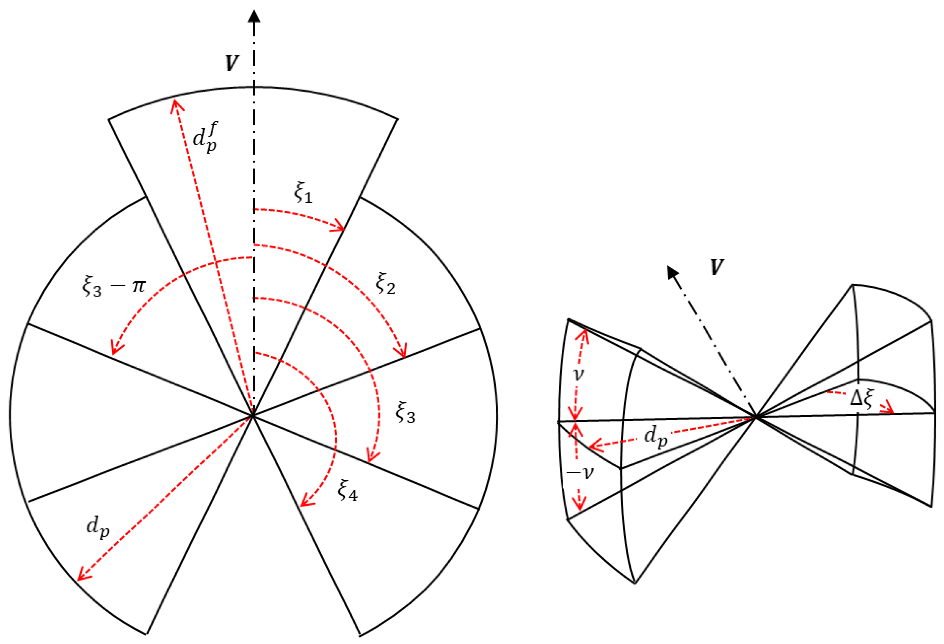
Figure 2.
Up: Trajectory and final location of each drone (drone 2: red, drone 3: yellow) with respect to neighbors’ sectors (Inset shows the interdistances with drones 1-2: blue, drones 1-3: red, drones 2-3: orange). Down: The speed corrections to achieve the new hover condition (drone 1: blue).
Figure 2.
Up: Trajectory and final location of each drone (drone 2: red, drone 3: yellow) with respect to neighbors’ sectors (Inset shows the interdistances with drones 1-2: blue, drones 1-3: red, drones 2-3: orange). Down: The speed corrections to achieve the new hover condition (drone 1: blue).
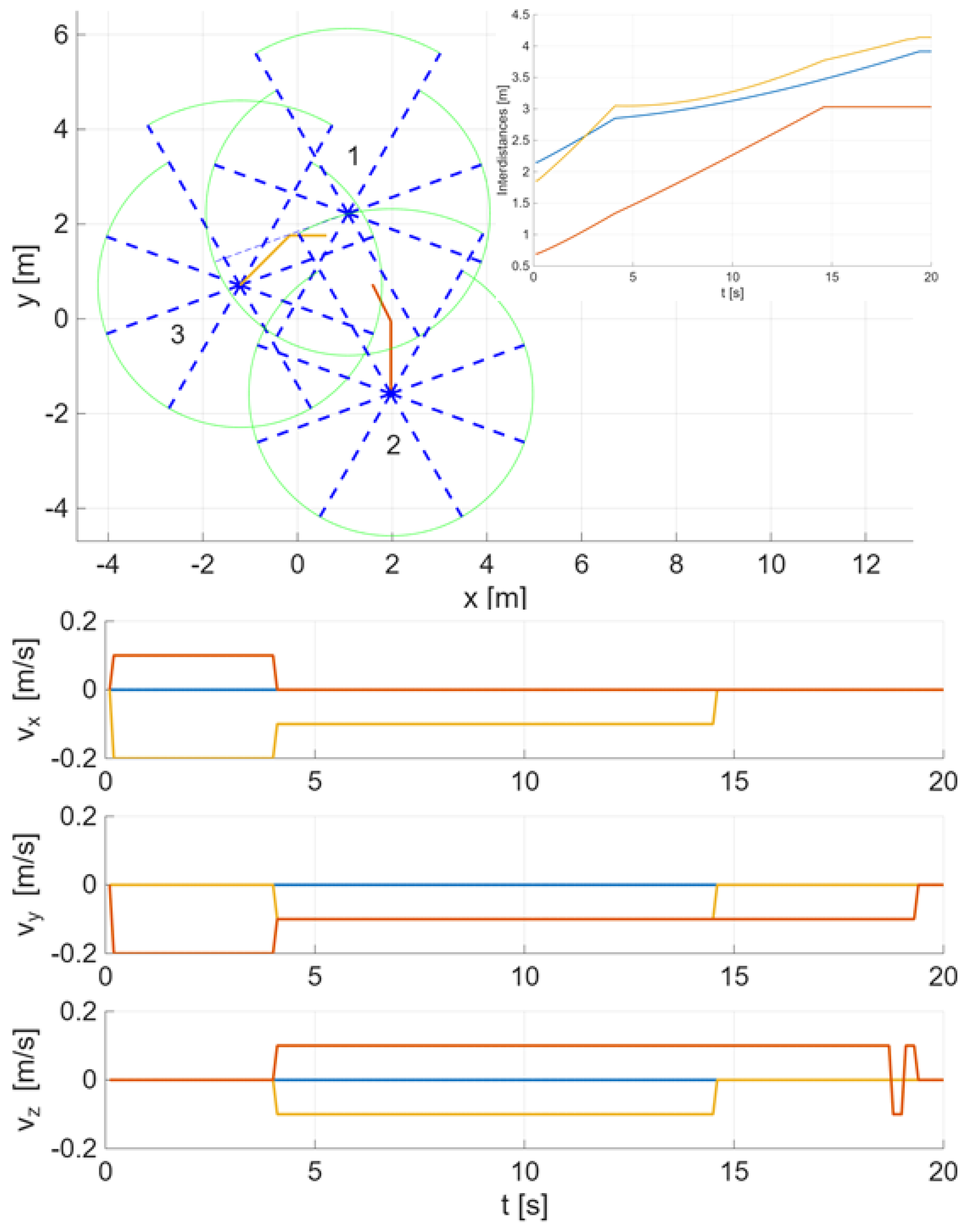
Figure 3.
Up: Interdistances between pairs of drones for all runs, compared to their steady state value. Down: Sample mean and variance as a function of time.
Figure 3.
Up: Interdistances between pairs of drones for all runs, compared to their steady state value. Down: Sample mean and variance as a function of time.
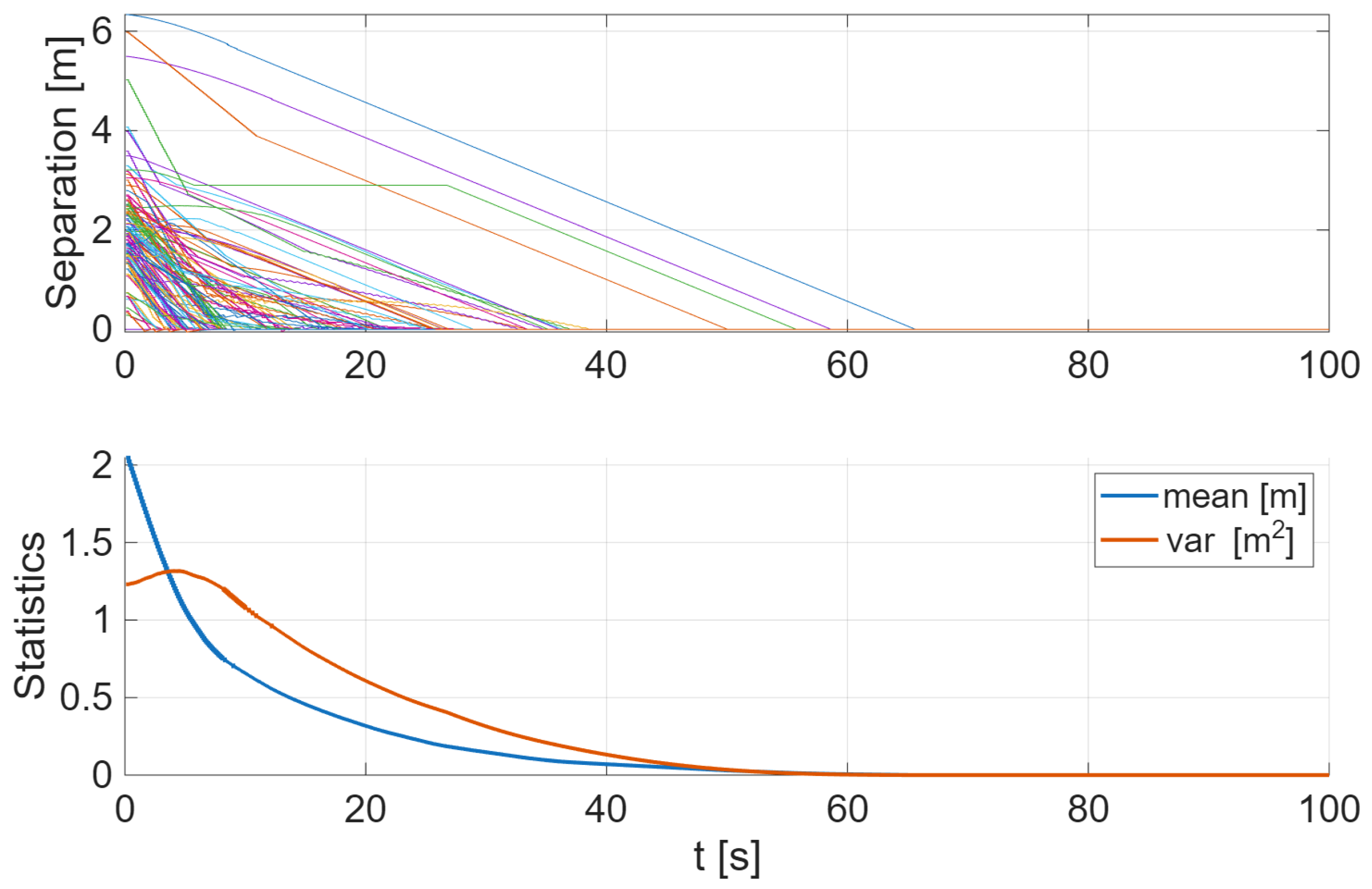
Figure 4.
Left: Grey-color image is showing the tracking of the two markers (inset zooms in showing their inter-distance ). Right: 3D representation of the pixel’s intensity (inset shows the binary image after threshold comparison).
Figure 4.
Left: Grey-color image is showing the tracking of the two markers (inset zooms in showing their inter-distance ). Right: 3D representation of the pixel’s intensity (inset shows the binary image after threshold comparison).
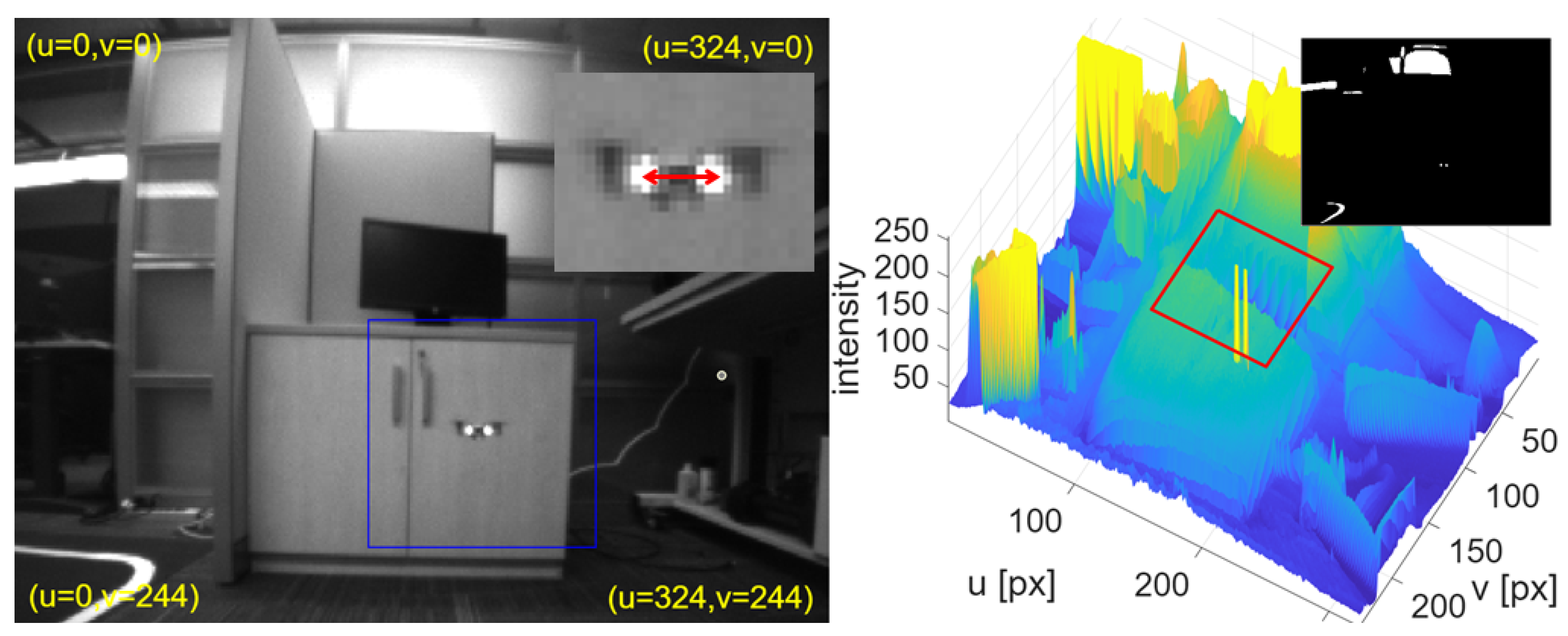
Figure 5.
Bio-inspired distances passively obtained from onboard camera.
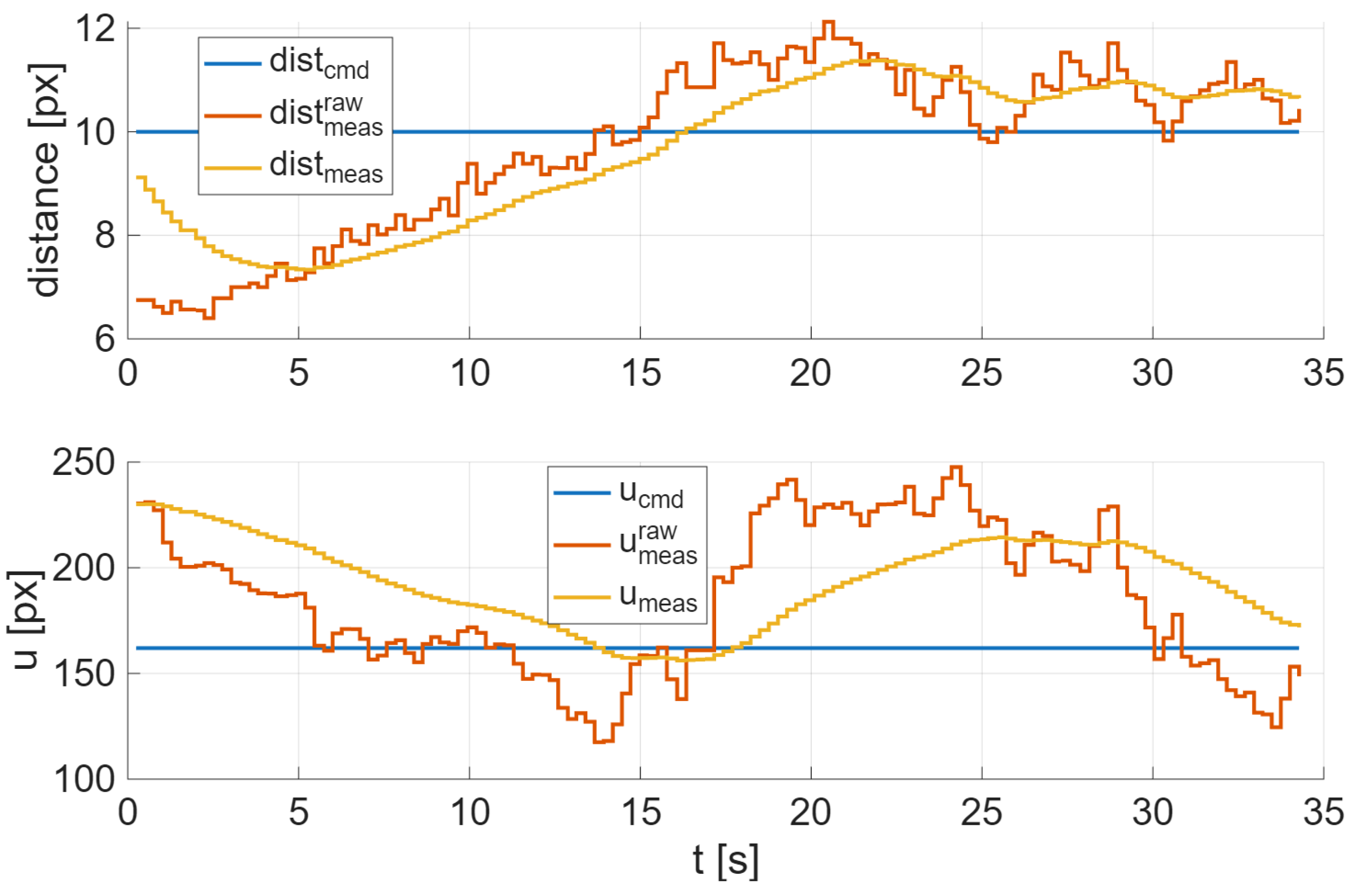
Figure 6.
Detected and matched features in two consecutive frames from the drone’s camera.

Figure 7.
Two different views of the point clouds and trajectories of both drones. First drone: red, second drone (unregistered): blue, second drone (registered): green.
Figure 7.
Two different views of the point clouds and trajectories of both drones. First drone: red, second drone (unregistered): blue, second drone (registered): green.
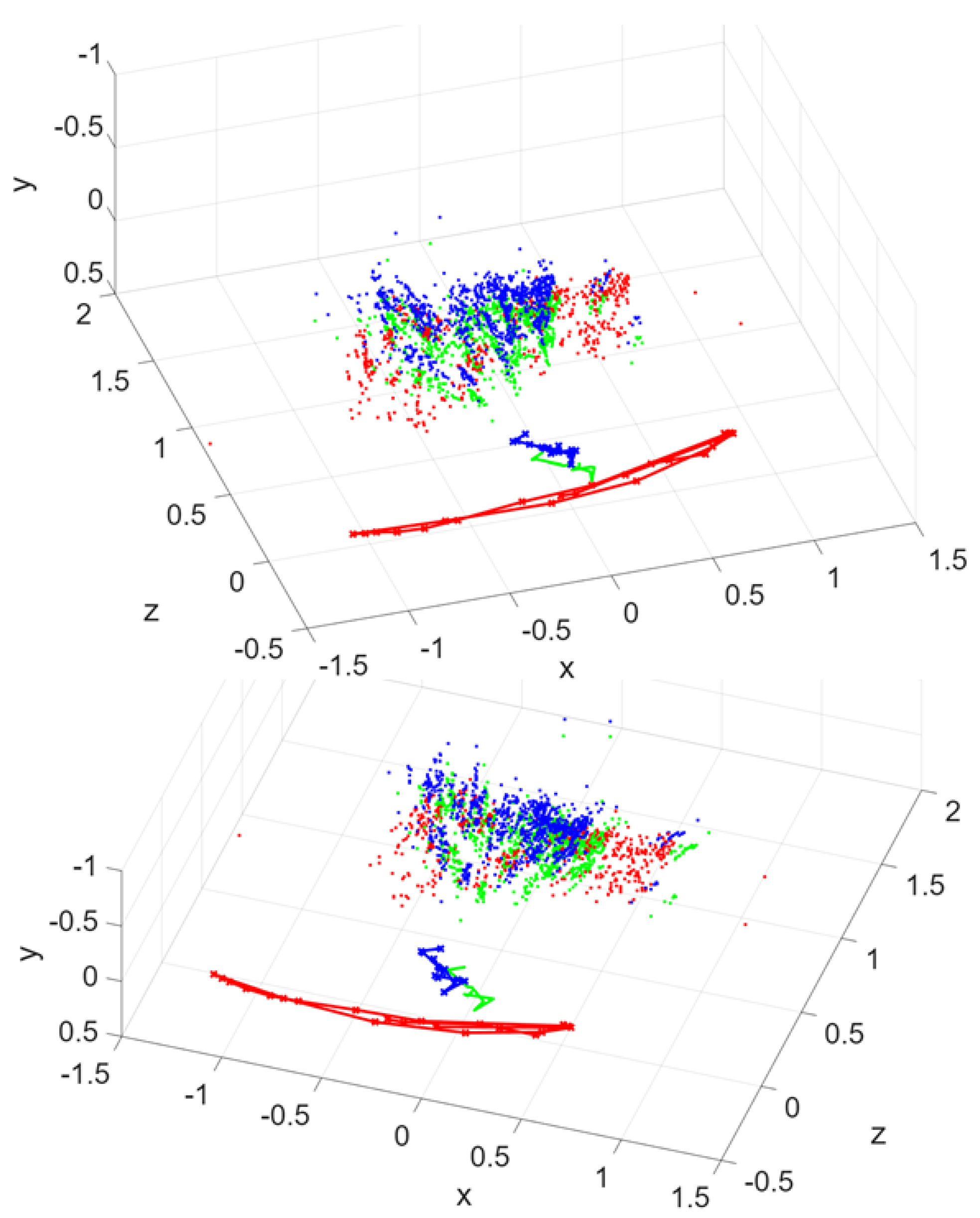
Figure 8.
Up: Scene in front of the drones. Down: Enhanced point cloud: first drone (red), and realigned second drone (green).
Figure 8.
Up: Scene in front of the drones. Down: Enhanced point cloud: first drone (red), and realigned second drone (green).
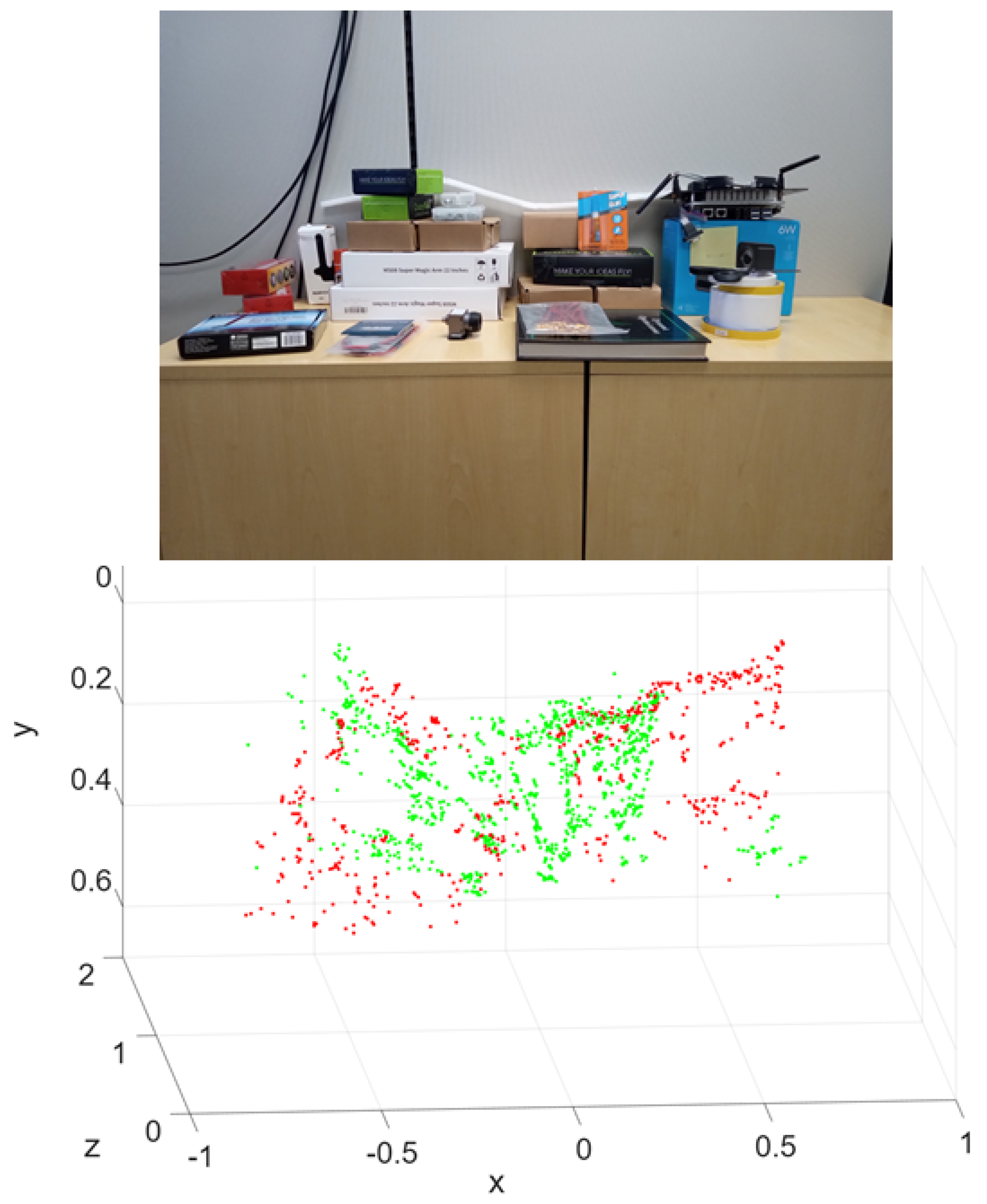
Figure 9.
Incremental pose estimation by registering the second point cloud with the first as it is being created.
Figure 9.
Incremental pose estimation by registering the second point cloud with the first as it is being created.
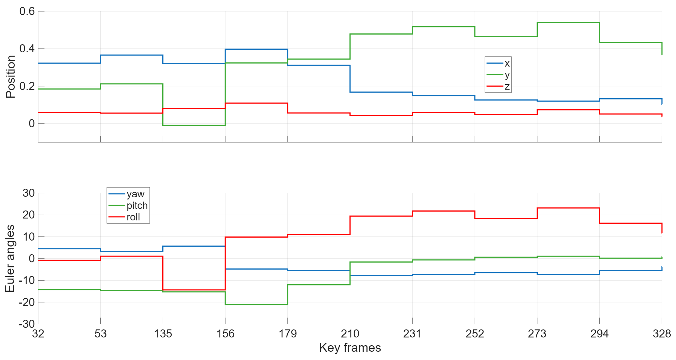
Figure 10.
Point clouds: car (red), drone’s uncorrected (blue), and realigned (green). Drone’s trajectories: uncorrected (blue), realigned (green), and true (purple). The inset shows the scene in front of the vehicles.
Figure 10.
Point clouds: car (red), drone’s uncorrected (blue), and realigned (green). Drone’s trajectories: uncorrected (blue), realigned (green), and true (purple). The inset shows the scene in front of the vehicles.
Disclaimer/Publisher’s Note: The statements, opinions and data contained in all publications are solely those of the individual author(s) and contributor(s) and not of MDPI and/or the editor(s). MDPI and/or the editor(s) disclaim responsibility for any injury to people or property resulting from any ideas, methods, instructions or products referred to in the content. |
© 2025 by the authors. Licensee MDPI, Basel, Switzerland. This article is an open access article distributed under the terms and conditions of the Creative Commons Attribution (CC BY) license (http://creativecommons.org/licenses/by/4.0/).
Copyright: This open access article is published under a Creative Commons CC BY 4.0 license, which permit the free download, distribution, and reuse, provided that the author and preprint are cited in any reuse.


