
Submitted:
05 December 2025
Posted:
07 December 2025
You are already at the latest version
Abstract
Laboratories across educational levels have traditionally required in-person attendance, limiting practical activities to specific times and physical spaces. This paper presents a technological architecture based on a system-on-chip (SoC) and a connectivist model, grounded in Connectivism Learning Theory, for implementing a remote laboratory in digital logic design using FPGA devices. The architecture leverages an Internet of Things (IoT) environment to provide applications and servers that enable remote access, programming, manipulation, and visualization of FPGA-based development boards located in the institution’s laboratory, from anywhere and at any time. The connectivist model allows learners to interact with multiple nodes for attending synchronous classes, performing laboratory exercises, managing the remote laboratory, and accessing educational resources asynchronously. This approach aims to enhance learning, knowledge transfer, and skills development. A four-year evaluation was conducted, including one experimental group using an e-learning approach and three in-person control groups from a Digital Logic Design course. The experimental group achieved an average performance score of 9.777, surpassing the control groups, suggesting improved academic outcomes with the proposed system. Additionally, a Technology Acceptance Model–based survey showed very high acceptance among learners. This paper presents a novel connectivist model, which we have called the Massive Open Online Laboratory.
Keywords:
remote laboratory
; FPGA devices
; system on Chip
; internet of things
; connectivism learning theory
1. Introduction
The COVID-19 pandemic was caused by the coronavirus known as SARS-CoV-2, with the first human cases reported in Wuhan, China, in December 2019 [1]. In March 2020, the WHO declared the COVID-19 pandemic, urging countries to adopt urgent and aggressive measures [2]. This situation drastically changed all our daily activities (work, education, family, etc.), in which we were immersed, and we had to adapt to all these changes within a few days.
To prevent the spread and contagion of COVID-19, educational institutions worldwide began closing, affecting over 1.5 billion learners globally [3]. In Mexico, academic activities were specifically suspended on March 23, 2020 [4]. As a result, the entire in-person teaching-learning model had to be completely transformed into a distance learning model, in which both learners and teachers had to adapt in a very short time. In this context, digital technologies such as Learning Management Systems (LMS) [5], native cloud storage applications [6,7], platforms for videoconferencing and virtual meetings [8,9], social media [10,11], and mobile instant messaging applications [12,13] were employed. All these technologies served as a means for transmitting information and connecting and communicating people, primarily learners and teachers, achieving Technology-Mediated Learning [14].
One of the major challenges in engineering university programs was the development of remote practical sessions. The practical activities conducted in each undergraduate program are highly varied due to the diversity of courses offered. Each course utilizes different elements depending on the field to which it belongs.
Courses related to the area of Digital Logic Design (DLD) use FPGA for conducting practical sessions. An FPGA allows the synthesis of digital logic designs using a Hardware Description Language (HDL). Programming an FPGA requires the use of a development board that contains the FPGA and all the necessary peripherals for conducting lab exercises.
Since it was not possible to use these development boards in person, some alternatives emerged, such as using simulators in class and creating videos by teachers to demonstrate the operation of the lab exercises to learners. However, none of these options provides learners with an adequate solution for conducting practical activities, as they do not allow physical interaction with the development boards. Another option is to create a remote laboratory.
A remote laboratory is a technological environment that enables remote access, programming, manipulation, interaction, and visualization of physical equipment available in educational laboratories at any level. This technological environment is implemented using a computational system through an embedded system based on SoC technology.
The remote laboratory offers the entire infrastructure necessary for learners to test their lab exercises from a distance. This infrastructure includes servers for transferring files to the physical equipment, remote access, applications to interact with and manipulate the physical equipment, as well as the use of cameras to stream video that allows visualization of the lab exercise results, and of course, a network connection for Internet access. This infrastructure enables remote laboratories to create the technological environment known as the IoT [15,16,17].
With the remote laboratory, learners can interact with the development boards located in the in-person laboratory from anywhere (home, office, university), at any time, and from any device (laptop, desktop computer, mobile device). This allows them to gain meaningful teaching and learning experiences by conducting lab exercises for the DLD area, making remote laboratory an accessible, available and usable technological environment. This allows them to acquire what is known as ubiquitous learning [18,19], or u-learning. They only need a computing system (personal computer, laptop, tablet, mobile, etc.) with computer-aided design and electronic design automation (CAD-EDA) tools and an internet connection.
The remote laboratory presented consists of twelve development systems that are currently operational at School of Computing Science of the National Polytechnic Institute, Mexico. Learners in the DLD and Computer Architecture courses are conducting various lab exercises using the remote laboratory with the e-learning approach. This approach is defined as the transfer of knowledge and skills through intelligently designed educational materials with the help of electronic media such as the Internet, Web 4.0, intranets, and extranets [20]. This approach enhances the accessibility and availability of educational materials for people without age, time, or learner limits. The Learning Management System (LMS) is a platform used in the e-learning approach and, therefore, in the presented system [21].
The paper is organized as follows: Section 2 describes the literature review on in-person and remote laboratories. Section 3 introduces the research methodology. Section 4 describes the analysis and design stage of the research methodology. Section 5 describes the implementation stage of the research methodology. Section 6 describes the results of the remote laboratory. Section 7 provides the Discussion and the section 8 concludes the paper.
2. Literature Review
The development of laboratories has been carried out in in-person, virtual, or remote modalities. In the in-person modality, they have been oriented towards various areas such as Control [22] and Robotics [23].
In the remote modality, several works have also been conducted by different researchers in various fields. Jonathan Alvarez and Sergio Gonzalez in [24] propose a remote laboratory to learn programming and physical computing through Python and Raspberry Pi. Chevalier and other researchers in [25,26] propose a remote laboratory used in Control engineering studies. Aditionally, Krishnashree Achuthan and other researchers in [27] propose a remote laboratory that operates a Universal Testing Machine (UTM). The researchers use the Transactional Distance Theory (TDT) to compare physical laboratory platforms and remotely triggerable platforms. Also, Zhiyun Zhang and others researchers in [28] present a Software-Defined Radio remote lab, which permit learners to experiment with real wireless communication, designing Radio Frequency systems with minimal code adjustments.
Particularly in the area of DLD, various remote laboratories based on FPGAs have been reported. Navas-González and other researchers in [29] present examples of practices sessions to teach and learn digital electronics using an FPGA-based remote laboratory. The remote laboratory allows for design verification, but there is no video transmission to view the results. A server is implemented on a SoC, which communicates serially with a Nexys3 board. The board sends the status of the peripherals to the SoC to update their state on the user’s screen. To carry out this communication, a module called RLAB Plant must be implemented in the learners’ practices. Additionally, Naoki Fujieda and Atsuki Okuchi in [30] propose a remote FPGA laboratory platform using a PIC18F4450 microcontroller-based board that communicates with FPGA devices remotely via commands. This is intended to give learners the sensation of interacting with the hardware in a remote laboratory environment. Besides, Michal Melosik and other researchers in [31] propose a remote laboratory focused on FPGA devices for the remote design and testing of electronics circuits. The laboratory hardware consists of an application server on a personal computer and Open Broadcaster Software (OBS) environment for streaming. Two cameras are used, one to visualize the FPGA board and another to monitor instruments like an oscilloscope. Two tasks are performed: using a temperature and humidity sensor and designing a sine wave generator. Also, Han Wan and other researchers in [32] propose a remote laboratory with an FPGA for a Computer Organization course using a web system. The laboratory hardware uses one FPGA for the practices and another FPGA as a monitor. Both FPGAs belong to the Spartan 6 family from Xilinx. A personal computer handles the remote connection to a cloud server. There is a web interface where the practice results are displayed. The researchers report that 50.9% of learners completed Practice 8 in 2017 with the remote laboratory, compared to 21.3% of learners who completed the same practice in 2016 without the remote laboratory. On the other hand, Yuxiang Zhang and other researchers in [33] propose a remote FPGA experiment for experiments of Computer Systems curriculum. The laboratory hardware uses an Artix-7 FPGA for the practices and a Zynq-7 SoC from Xilinx as a controller to program the FPGA’s binary file through serial slave configuration. The researchers test the platform with the implementation of a 32-bit MIPS architecture processor capable of running a modified version of the Linux kernel.
Thang Manh Hoang and other researchers in [34] propose a remote laboratory for teaching FPGA and HDL. The laboratory hardware uses an Altera Cyclone II 2C20 FPGA for the practical exercises, which is controlled through a PIC16F877A microcontroller. Additionally, Toyoda and other researchers in [35] propose an FPGA-based remote laboratory implemented in a hybrid cloud for semi-automatic FPGA runs experiments. The laboratory consists of development systems from Altera. The user only needs to prepare their HDL code and FPGA configuration parameters, which are then sent to the laboratory. Finally, Aramburu and other researchers in [36] propose a cross-national remote laboratory based on FPGAs, implemented by the universities UPNA in Spain and UNIFESP in Brazil. The laboratory consists of 14 Altera development systems from both universities. They use a Raspberry Pi 3 B+ SoC to install the server and a Logitech webcam for video streaming.
Muhammad Alhammami in [37] outlines the development of a Hardware Development Kit (HDK) for a remote training platform based on FPGA. The HDK is equipped with a Raspberry Pi, a screen, a camera, LEDs, and the EP3C16Q240 FPGA chip from Altera. The raspberry Pi is to run a service as a loading or programming server for the FPGA. They present the design of a mechanical enclosure. To interact with the HDK, the VNC Viewer is used. Additionally, Rithea Sum and other researchers in [38] proposes a remote embedded system design approach utilizing Zynq 7000 FPGA, providing a web-based platform for learners to remotely test and debug their designs, with a focus on efficient signal acquisition and effective debugging and analysis. The methods used in the study include the implementation of a lab module with adaptive run-length-encoding data compression with an average compression ratio of 2.90 across three benchmark signals. Also, Carlos Cruz and others researchers in [39] proposes a remote laboratory using a a Nexys 4 FPGA Board. The designed remote setup allows learners to reserve laboratory time by creating customized environments for a wide range of experiments across different subjects. They use a remote computer, camera, sensors and motor for the development of experiments. There is one lab exercise reported. The study used a questionnaire with 17 questions to gather learners’ perceptions of the remote lab. The results were derived from the Electronic Design course with over 70% of learners preferring to combine real lab with remote lab. On the other hand, Guerrero-Osuna and others researchers in [40] presents a remote laboratory based on a Basys 3 FPGA Board, a Raspberry Pi 5, Google Firebase services and a web platform called UAZ Labs. They used a waterfall methodology integrating IoT and Cloud Computing technologies to facilitate close interaction between hardware and software. There are 3 lab exercises reported focuses on controlling DC, servo, and stepper motors. The testing phase involved 50 robotics and mechatronics engineering learners who participated in hands-on sessions for one month, followed by a structured survey evaluating their experience, interaction, and the educational relevance of the platform. Finally, Ballina and other researchers in [41] describe a remote laboratory with a cluster of an AMD Zynq UltraScale and a multiprocessor systems-on-chip (MPSoC) based on FPGA technology. The cluster is used for teach the concepts of data transfer and parallel processing across CPU and FPGA. The laboratory is used in a parrallel and heterogeneous computing course or in a the development of accelerators for ad-hoc computing course. The autors present 5 exercises for heterogeneous computing.
3. Research Methodology
In this paper, a quantitative research approach with an exploratory and explanatory scope is used. The research methodology is shown in Figure 1.
Figure 1 shows three different stages: Analysis and Design, Implementation, and Evaluation and Results. These stages are explained below:
4. Analysis and Design Stage of the Research Methodology
4.1. General Architecture
In this stage, the General Architecture of the remote laboratory for the DLD area is presented, using reconfigurable technology based on FPGA, a connectivist model based on Connectivism Learning Theory, and an embedded system based on IoT for implementation. Figure 2 shows the general architecture.
The general architecture consists of two important components, which are:
- On-site implementation of lab exercises.
- Use of remote laboratories based on IoT.
These components are described below:
4.2. On-Site Implementation of Lab Exercises
In this first component, the learner performs the analysis, design, implementation, simulation, constraints assignment, and BitStream file generation of the lab exercises to be developed using a CAD-EDA tool (ISE or Vivado by Xilinx) [42]. In this development environment, a project is created by selecting the FPGA of the Nexys 4 development board [43]. The sequence of actions for the on-site implementation of lab exercises is shown in Figure 3 and described below:
- Design procedure of the digital logic lab exercise: The Digital Design methodology is used to obtain the entity, the Algorithmic State Machine (ASM), the functional blocks, the datapath and the control unit for the lab exercise.
- Project creation with CAD-EDA tool: In the development environment, a project is created by selecting a target device, which can be either a Complex Programmable Logic Device (CPLD) or FPGA.
- Lab exercise simulation with HDL testbench: The HDL program is simulated to verify its correct operation according to the exercise specifications using a set of test vectors with a Test Bench file. For this, the ISE simulator integrated into the CAD-EDA tool is used.
- Pins assignment in constraint file: Pin assignment in the constraint file (.xdc) is performed using a virtual connector created within the technological architecture, which is called LAB REMOTE. This connector contains 24 virtual switches for assigning input pins. The output pin assignment is done through the peripherals on the development board.
- BitStream file generation: Finally, the syntheses, mapping, place and route and BitStream file (.bit) generation is performed.
4.3. Use of Remote Laboratories Based on IoT
In this second component, the learner accesses to the remote laboratory to interact, program, manipulate, visualize, and verify the results of the lab exercise on the FPGA using the Nexys 4 development board. The remote laboratory is implemented on an embedded system with SoC technology. The sequence of actions for using the remote laboratory is shown in Figure 4 and is described below:
- BitStream and constraints files transfer: To achieve this, an SSH server is used for file transfer from a terminal on any operating system (Windows, Linux, MacOS) executing the scp command. In addition, an SSH client for desktop or mobile devices can be used.
- Access to video server: A video web server allows visualization of the results from each lab exercise performed on the Nexsys 4 development board.
- SSH connection to remote laboratory: Remote access to the remote lab is achieved through the SSH server using the username and password provided by the instructor.
- FPGA programming with BitStream file (.bit): The BitStream file is programmed in the FPGA device using an application developed for the SoC.
- Lab exercise verification with constraints file: The lab exercise is verified through an application developed for the SoC.
5. Implementation Stage of the Research Methodology
In this stage the following modules are explained:
- Technological Architecture of the Remote Laboratory.
- Sequence of lab exercises for a DLD course.
- Connectivist Model based on Connectivism Learning Theory.
5.1. Technological Architecture of the Remote Laboratory
To implement the general architecture shown in Figure 2 a technological architecture for the development of the remote laboratory is proposed. Figure 5 shows the main components of the technological architecture.
Three important components shown in Figure 5 are explained below:
- V-Model methodology.
- Embedded System Based on IoT.
- SoC-FPGA Interface.
5.1.1. V-Model Methodology
For the analysis, design, and implementation of the remote laboratory using an embedded system, an adaptation of the V-Model Methodology proposed by Coop [46] was used for the development of SoC-based embedded systems. This methodology is shown in Figure 6.
Figure 6 shows the stages of the V-model methodology, from the specification of requirements to the operational testing of the system. This methodology allows returning to previous stages to make the necessary adjustments and ensure that the established requirements are met. In addition, the methodology supports the use of Unified Modeling Language (UML) in each stage [47], enabling a detailed description and a standardized design.
5.1.2. Embedded System Based on IoT
An embedded application was developed using SoC technology and a Linux-based operating system, specifically Raspberry Pi OS Lite (64-bit), which has an image size of 423 MB [48]. The SoC consists of a Raspberry Pi 3 Model B+, which has the following features [49]:
- 64-bit Cortex A53 Processor, with four cores, in Broadcom BCM2837B0 SoC.
- 1GB LPDDR2 SDRAM, Gigabit Ethernet over USB 2.0.
- 2.4GHz and 5GHz IEEE 802.11.b/g/n/ac wireless LAN, Bluetooth 4.2, BLE.
- Peripherals: SPI, I2C, UART, I2S, USB, GPIOs.
Although a Raspberry Pi 3 Model B+ SoC was used, it could be replaced by a Raspberry Pi 4 Model B or a Raspberry Pi 5. The SoC uses a Camera Module V2 for Raspberry Pi [50], based on Sony’s IMX219 8-megapixel sensor [51]. This camera communicates with the SoC via the MIPI CSI-2 protocol [52] for live video streaming.
Besides, two servers were configured on the embedded system, as described below:
- SSH server. This server uses the Secure Shell protocol for encrypted communication and is managed by the systemd initialization system.
- Video web server. This server is implemented using motion, which is used through a web application, so a browser is used for access. Motion is a configurable program that monitor video signals from many types of cameras and perform actions when movement is detected [53].
Additionally, two Linux shell applications were programmed and implemented on the embedded system to interact with the Nexys 4 FPGA development board, as described below:
- FPGA programming application. An application called progFPGA is used to program the FPGA device and relies on the drivers for the Advanced RISC Machine (ARM) architecture provided by Digilent Inc. These drivers are managed through the Join Test Action Group (JTAG) standard.
- Virtual switches application. An application called inputFPGA is used to verify the lab exercise and relies on the GPIOs of the SoC. This application allows the manipulation of up to 24 virtual switches which are labeled with the input port names defined in the user constraints file.
5.1.3. SoC-FPGA Interface
This manipulation interface is an electronic circuit that connects the SoC’s 40-pin connector to the Nexys 4 development board through the PMOD connectors. The block diagram of this interface is shown in Figure 7.
The functions provided by the SoC-FPGA Interface shown in Figure 7 are as follows:
- Create virtual switches. A connector referred to as "LAB REMOTE" is created, which supports the operation of up to 24 virtual switches. These virtual switches are shown in Table 1
- Configure a Real-Time Clock/Calendar (RTCC). The SoC lacks an integrated Real-Time Clock Calendar (RTCC) for system date and time configuration; instead, it relies on a Network Time Protocol (NTP) server to synchronize the system clock. When an RTCC is required, it must be implemented as an external peripheral to the SoC. The SoC–FPGA interface provides a connector compliant with the IIC bus specification [54], enabling the integration of external devices. Consequently, a custom electronic board was designed to incorporate an external RTCC, model DS1338, from Analog Devices [55] into the SoC.
- Configure a Crypto-Authentication device. These devices feature a cryptographic coprocessor that performs hardware-based encryption algorithms for IoT applications. A custom electronic board was designed for the connector compliant with the IIC bus specification of the SoC–FPGA interface to integrate an external Crypto-Authentication device, model ATECC608, from Microchip Inc [56].
- Provide an USB to serial UART interface. The SoC–FPGA interface provides a connector compliant with the UART interface. It enables the interconnection of external peripherals such as an USB to serial UART interface (FT232R) [57]. The FT232 device allows a console access to the SoC operating system and access to programming, configuration, updating, and maintenance tasks for the embedded system applications.
5.2. Sequence of Lab Exercises for a DLD Course
The remote laboratory has been used in the DLD courses since 2021 to date, with nine lab exercises covering the course content. The lab exercises are shown in Table 2.
Lab exercise 1 through 8 are explained in general terms, while lab exercise 9 is explained in detail as it encompasses the full thematic content of the course.
Lab exercise 1 involves integrating different combinational logic circuit elements such as the multiplexer, comparator, and code converter into an application that allows the use of various HDL structures, including concurrent, sequential and conditional. In this lab exercise, learners review and/or acquire the foundational knowledge needed for the course.
In lab exercise 2, learners design, implement and test an SR Flip-Flop (FF), JK-FF, T-FF and D-FF based on the equations obtained from their extended truth tables. The implementation is carried out using the D-FF and HDL on an FPGA. Through this lab exercise, learners apply and reinforce the theoretical knowledge acquired on Latches and FF’s.
In lab exercise 3, learners design, implement and test a circuit that performs the functions of a register, including load, hold, shift-left, and shift-right operations. The implementation is carried out at different levels of abstraction using HDL on an FPGA. Through this lab exercise, learners apply and reinforce the theoretical knowledge acquired on registers: architectures and applications.
In lab exercise 4, learners design, implement and test a 4-bit sequence detector without overlap using HDL on an FPGA. The sequence to detect is 1101 where the methodology for designing sequential circuits is applied. Through this lab exercise, learners apply and reinforce the theoretical knowledge acquired on Deterministic Finite Automaton (DFA) with output called Mealy Machines.
In lab exercise 5, learners design, implement, and test a multiplexed message using HDL on an FPGA. The message has four symbols and is displayed on a module of four multiplexed common anode displays. Also, the methodology for designing sequential circuits is applied. The implementation is carried out in two ways: a static message without movement and a moving message in marquee mode. Through this lab exercise, learners apply and reinforce the theoretical knowledge acquired on DFA with output called Moore Machines.
In lab exercise 6, learners design, implement and test counters using HDL on an FPGA. They analyze an up-counter with Enable for obtaining a generic equation using a Moore Machine and applying the methodology for designing sequential circuits. Additionally, they implement counters using high-level operators + and −. Through this lab exercise, learners apply and reinforce the knowledge acquired on counters.
In lab exercise 7, learners design, implement and test BCD, ring and Johnson counters using HDL on an FPGA. They analyze these counters through their Mealy and Moore Machines and implement them using packages and components. Through this lab exercise, learners apply and reinforce the knowledge acquired on special counters.
In lab exercise 8, learners design, implement and test an application that determines whether a person enters or exits a room and counts the number of people in the room using two optical sensors and BCD counters. The application is implemented using a Mealy Machine analyzed with high-level HDL. Packages and components are used for the implementation. Through this lab exercise, learners apply and reinforce the knowledge acquired on Mealy Machines and special counters.
Practice 9 is described in detail below:
5.2.1. Algorithmic State Machine Lab Exercise
ASM are used to model dedicated cores through a flowchart that represents the state transitions and outputs generated by Mealy and Moore machines. The resulting digital logic design enables the execution of a specific algorithm in hardware.
In this lab exercise, a digital logic system is designed, implemented, and tested using HDL on an FPGA to determine the number of 1-bits in a 22-bit register through an ASM.
The design begins with the analysis of the algorithm to be implemented, which is shown below:
From Algorithm 1, the ASM is obtained, which contains the actions to execute the practice’s algorithm. The ASM is shown in Figure 8.
| Algorithm 1 Pseudocode algorithm of the ASM lab exercise |
|
From the ASM in Figure 8, the microarchitecture shown in Figure 9 is obtained. This microarchitecture is known as the datapath.
In this Microarchitecture, the Data Path of the design is shown, where the following functional blocks are presented:
- Register A. This register contains the 22-bit number to be analyzed.
- BCD Counters. They count the number of 1-bits contained in Register A. The algorithmic diagram of the BCD counters is shown in Figure 10.
- Ring Counter. Performs the multiplexing of the digits from the BCD counters on the 4 multiplexed common anode displays.
-
ROM Memory. Performs the decoding of the 4 bits from the BCD counters to the 7 segments of the display. For a ROM memory with an organization of bits, a data bus called with n bits, and an address bus called with bits, its equation is given by:Where:
-
Control Unit Here is the automaton of the control unit obtained by replacing the actions of the ASM in Figure 8 with the control signals of each element of the Data Path shown in Figure 9. This automaton is shown in Figure 11.The automaton of the control unit is defined by the 9-tuple:Where:For each state , each input symbol and each input signal , the transition function is defined as follows:The output function represents the Mealy-type outputs of the ASM. Additionally, for each state , each input symbol , each input signal , each output signal , and each output value , the function is defined as follows:The output function represents the Moore-type outputs of the ASM. Additionally, for each state , each output signal , and each output value , the function is defined as follows:
With this lab exercise, learners apply and reinforce the knowledge acquired in the theoretical topics of special and applications counters, Memories, and ASM. Additionally, the learner applies the digital systems design methodology using ASM symbols for the implementation of the lab exercise.
Each element shown in Figure 9 is implemented using VHDL. Specifically, the learners apply the design using packages and components in VHDL, utilizing component parameterization. Furthermore, the control unit in Figure 11 is implemented using functional description by specifying states through the TYPE directive in VHDL. Functions, procedures, and file reading in VHDL are also implemented.
5.3. Connectivist Model Based on Connectivism Learning Theory
To conduct theoretical topics, learning activities, and the development and assessment of lab exercises for the DLD course, the Connectivism Learning Theory was applied. This theory is one of the most relevant frameworks in smart e-learning environments [21].
The Connectivism Learning Theory is the thesis that knowledge consists of sets of connections between entities, such that a change in one entity can result in a change in the other, and that learning is the growth, development, modification, or strengthening of those connections [58]. Connectivism is the integration of principles explored by chaos, network, complexity, and self-organization theories [59].
Siemens defines the principles of connectivism in [59]. Under the principles of connectivism, Siemens and Downes [58] proposed, in 2008, a connectivist learning activity environment, non-formal, called a Massive Open Online Course (MOOC). In this type of environment, there is no predefined content or thematic sequence. The learner makes decisions regarding the selection of thematic content and learning objectives. This approach gives the learner independence to establish a personal learning path based on informal learning [60]. This allows learners to acquire connective knowledge, which is distributed knowledge resulting from the connections formed by the properties of various entities included in the MOOC and their interaction [61].
In this paper, a novel connectivist model was developed for the DLD course using remote laboratories, which we have called as a Massive Open Online Laboratory (MOOL). The MOOL is described through different models, two of them are derived from the Unified Modeling Language (UML). UML is a diagram-based modeling language for the specification, visualization, construction, and documentation of any complex system [62]. It has been used to model software engineering systems as well as other types of systems [63,64,65,66,67]. In this paper, UML is used to model the connectivist environment. The models used are as follows:
- Entity model.
- Use case diagram.
- Activity diagram.
5.3.1. Entity Model
This model shows the functionality, connections and interactions of each entity. The model is shown in Figure 12.
Figure 12 shows the different entities of the connectivist model, each of them is explained below.
- Learning Management System (LMS) for DLD course. A LMS is designed to enable educators to manage, measure, and enhance learning experiences. Learning activities and didactic resources in LMS are lecture notes, instructional design documents, class videos, assignment and exercises. The LMS is shown in Figure 13.
- Cloud Storage. In this entity a native application is used for storing the content of the DLD course.
- Video conferences. This entity utilizes a platform that allows scheduling and initiating video conference sessions. In these sessions, participants can join to collaborate through voice, video, and screen-sharing functions. This platform is used to deliver synchronous theoretical class sessions, which are recorded for later storage in the cloud. This is done so that the videos can be accessed asynchronously by learners. During these sessions, learners’ questions regarding the covered topics are clarified and addressed.
- Virtual meetings. This entity utilizes a video communication service to conduct video conferences and virtual meetings. This service is used to hold synchronous class sessions for the review of lab exercises via the remote laboratory. During these sessions, learners demonstrate the functionality of each lab exercise to the instructor by implementing their VHDL program, running simulations via test bench file, and verifying the design on the FPGA through the remote laboratory. Learners’ questions related to the lab exercises are also clarified and addressed in these sessions.
- Platform for video storage. This entity uses a social media platform that allows hosting and sharing videos showcasing the remote laboratory’s operation. These videos can be accessed online asynchronously by the learners.
- Instant messaging application for mobiles devices. This entity uses a platform to communicate with all learners in the course for the activities shown in Figure 9. In addition, this node enables academic interaction among learners.
- Remote Laboratory. This entity uses the remote laboratory, where learners test lab exercises by programming the FPGA, interacting with it and manipulating it.
5.3.2. Use Case Diagram
Within the structural view is the use case diagram, which models the functionality of a system as perceived by the actors interacting with it [71]. The use case diagram of the connectivist model is shown in Figure 14.
Figure 14 shows the different use cases of the connectivist model, each of them is explained below.
- Deliver synchronous classes. In this use case, the professor and learner actors interact during synchronous classes. The participating entities are an instant messaging application for mobiles, video conferences, the LMS, and cloud storage.
- Generate didactic resources. In this use case, the professor actor generates didactic resources throw the editing in the LMS. The participating entities are the LMS, platform for video storage, and cloud storage.
- Review didactic resources. In this use case, the learner actor reviews didactic resources from the LMS. The participating entities are the LMS, platform for video storage, an Instant messaging application for mobiles, and cloud storage.
- Conduct learning activities. In this use case, the learner actor conducts learning activities from the LMS. The participating entities are the LMS, platform for video storage, an Instant messaging application for mobiles, remote laboratory, and cloud storage.
- Lab exercise assessment. In this use case, the professor, learner, and embedded system actors interact during the lab exercise assessment. The participating entities are an instant messaging application for mobiles, virtual meetings, the LMS, and remote laboratory.
5.3.3. Activity diagram
The dynamic behavior of the connectivist model can be analyzed through the activity diagram view [71]. These diagrams show the flow control of the activities performed by the learner, professor, and embedded system actors from de use case diagram, and each entity within the connectivist model. In the Figure 15 the activity diagram of the “Lab Exercise Assessment” use case is shown.
Figure 15 shows the interactions involved between the professor and learner actors and the instant messaging application for mobiles, virtual meetings, the LMS, and remote laboratory entities.
6. Results
The tests performed on the proposed system, as well as the evaluation of the results obtained, are divided into the following sections:
- Testing and results of server’s performance on the SoC.
- Testing and results of the ASM lab exercise conducted in the remote laboratory.
- Testing and results of the Technology Acceptance Model (TAM)
- Learning outcomes and assessment.
These tests were carried out using the remote laboratory, which consists of twelve development systems that have been used in the DLD courses of the Computer Systems Engineering program at the Higher School of Computing of the National Polytechnic Institute located in Mexico City.
Figure 16 shows the physical implementation of a system used in the remote laboratory, which consists of a System On Chip, SoC-FPGA interface, the FPGA development board, and power supply.
6.1. Testing and Results of Server’s Performance on the SoC
Figure 5 shows the video server and the SSH server implemented on the SoC used in the remote laboratory. Their testing and evaluations are described below:
6.1.1. Testing and Results of Video Server’s Performance no the SoC
The video server uses a Raspberry Pi Camera v2 [50] based on Sony’s IMX219 sensor [51]. This server allows a maximum of 10 users to connect. The server was tested with a program that displays the message "Lab-rEnnoto-ESCOnn-IPN!" in marquee mode using a 4-digit multiplexed common anode display module. The camera resolution is 1024x768 pixels at 20 frames per second. The Linux operating system command was used to obtain the CPU and memory usage percentages, which are shown in Table 3.
Table 3 shows that the maximum CPU usage percentage is 85.1, which corresponds to a single core of the processor. The remaining three cores are used for running other system processes. The percentage of memory used in the SoC is only 5.2% for 10 connected users.
6.1.2. Testing and Results of SSH Server’s Performance on the SoC
To test the SSH server, the JMeter application [72] was used. With this application, load tests were performed with a range of 5 to 50 users in time intervals between 1 second and 60 seconds. The results obtained are shown in Table 4.
In Table 4, it is shown that the system can handle up to 15 users within 1 second of response time. Additionally, it is observed that a maximum of 19 users can connect starting from 3 seconds of response time. This allows the connection of up to 6 groups of 3 learners each, along with one instructor.
6.2. Testing and Results of the ASM Lab Exercise Conducted in the Remote Laboratory
Each practice shown in Table 2 is analyzed, designed, and implemented using the Vivado v2022.2.2 tool from Xilinx [42] and the Nexys 4 development board [43] with the XC7A100TCSG324 FPGA [73]. The testing and evaluation of ASM lab exercise results is reported below.
Each element of the microarchitecture shown in Figure 9 is implemented using VHDL. Figure 17 shows the implementation of the control unit.
After the implementation of the lab exercise using VHDL, a simulation was performed using a Testbench file with the test vector , which contains 12 bits set to one. This vector allows for verifying the correct operation of the lab exercise. Figure 18 shows the simulation result.
Figure 18 shows the right-shift operation in the register’s output and the increment in the BCD counters from 00 to 12. The result is finally displayed on the common anode displays.
Next, the input and output terminal assignment is performed using the constraints file and the virtual switches from the Remote Lab connector. In this moment, the synthesis, place and route, and generation of the BitStream file for the ASM lab exercise are carried out. After this process, the FPGA resources used are obtained, as shown in Table 5.
Timing information is also obtained, which is shown in Table 6. The maximum frequency of the design is obtained using equation (22).
Finally, the testing and evaluation of the ASM lab exercise is carried out using the remote laboratory and the connectivist model, as shown in Figure 19.
6.3. Testing and results of the TAM
The TAM is a theoretical framework developed by Fred Davis [74] in the 1980s to understand and predict user acceptance and adoption of technology. The model uses the following variables:
- Perceived Usefulness - PU.
- Perceived Ease of Use - PEU.
- Intention to Use - IU.
In this paper, the TAM is adapted with three additional variables, which are shown in Figure 20.
- Technology Application - TA Refers to the extent to which a learner utilizes foundational knowledge from areas related to the technology being used. This allows the learner to both apply previously acquired knowledge and learn new topics.
- Support Digital Resources - SDR Refers to the digital resources available to the learner for managing and using the technology. These resources include online user manuals, videos, supporting software, and Learning Management Systems.
- Acquired Digital Skills - ADS Refers to the acquired knowledge through learning digital technologies necessary for using the new technology. These digital technologies include CAD-EDA tools for managing and programming the physical device of the remote laboratory and applications for remote interaction.
Derived from the different variables of the TAM adapted shown in Figure 20, a data collection instrument was designed, consisting of a survey with 20 items. These items are shown in Table 7.
The items shown in Table 7 were applied the form of a self-administered survey applied to 28 learners from group 2CM16 of the DLD course taught during the 2021-2 semester, using a Likert scale. The Likert scale consisted of the values: totally disagree (td), disagree (d), neutral (n), agree (a), and totally agree (ta). Regarding item SP1, the surveyed learners were between 19 and 24 years old, with 46.4% being 20 years old. Regarding item SP2, 75% of the surveyed learners were male. The results obtained from the remaining items are shown in Table 8.
To determine the reliability of the data collection instrument, Cronbach’s alpha coefficient was used [75,76], which is obtained by calculating the variances of the responses given by the sample for each item. Its equation is given by:
The Cronbach’s Alpha Coefficient was calculated over all the items in the survey. This was done using a program developed with the Pandas library [77] and the Jupyter Notebook development environment [78]. The calculated value of the Cronbach’s alpha coefficient is 0.77 , which indicates that the data collection instrument has good internal consistency [75].
6.4. Learning Outcomes and Assessments
To evaluate the remote laboratory, a quasi-experimental field design was employed [79], with the experimental group 2CM16. In this course, the connectivist learning model proposed in Figure 12 was used, and the course followed an e-learning approach. The learners were assessed using the rubric shown in Table 9.
The evaluation results of the experimental group 2CM16 are presented alongside the evaluation results of three control groups from the same course in the years 2017, 2018, and 2019, where the courses were taught in person. Each group consists of 33 enrolled learners, whose grades are used for the descriptive statistical analysis. The sample mean was calculated as a measure of central tendency. In addition, the sample variance , standard deviation , and coefficient of variation were calculated as measures of dispersion. This was done using a program developed with the Pandas library [77] and theJupyter Notebook development environment [78]. The results are shown in Table 10.
In Table 10, it can be observed that the grades’ sample mean of the experimental group 2CM16 from the year 2021 is higher than the average in the groups from 2017, 2018, and 2019.
7. Discussion
7.1. Discussion of Server’s Performance on the SoC
As for the servers implemented on the embedded system, the video server supports up to 10 connected users, depending on the configured camera resolution, the number of frames transmitted per second, and the available network bandwidth. For 10 users, the video server on the embedded system shows a CPU usage of 85.1% on a single core and 5.2% RAM usage, indicating that the processing and memory resources provided by the embedded system are sufficient for the remote laboratory’s operation. Furthermore, an embedded system with fewer processing and memory resources could also be used, resulting in lower power consumption and reduced costs.
The SSH server can connect up to 19 users simultaneously, allowing up to 6 groups of 3 learners each, along with one instructor per remote laboratory. This is due to the maximum number of connections allowed by the network manager.
7.2. Discussion of the ASM lab Exercise
The ASM lab exercise illustrates the different stages of the DLD methodology, as shown in Figure 3, as well as the stages for using the remote laboratory, shown in Figure 4. The utilization of LUT and FF resources in this lab exercise is less than 1%, demonstrating the high availability of FPGA resources. Furthermore, the maximum frequency achieved is 452 MHz for this lab exercise; however, the other lab exercises use different FPGA resources, with maximum frequencies of at least 400 MHz. Additionally, further lab exercises can be proposed beyond those presented here.
7.3. Discussion of the TAM
The TAM adapted is applied, using six variables, to assess learners’ acceptance of the proposed technological architecture and connectivist model. The Likert scale survey conducted with learners shows a percentage greater than 92.9% for the totally Agree response in the Perceived Usefulness variable for all items, indicating that the RL supports the completion of DLD lab exercises.
For the variable of Perceived Ease of Use, the percentage exceeds 89.3% for the totally Agree response across all items, indicating that the applications developed on the SoC allow effective interaction and manipulation of the remote laboratory through the FPGA-based development board.
Furthermore, for the variable of Technology Application, the percentage exceeds 89.3% for the totally Agree response across all items, suggesting that knowledge acquired in other courses is applied and/or learned in the use of the remote laboratory.
Besides, for the variable of Support Digital Resources, the percentage exceeds 92.9% for the totally Agree response across all items, indicating that the support materials provided follow an appropriate techno-pedagogical design for using the remote laboratory.
Additionally, for the variable of Acquired Digital Skills, the percentage is over 85.7% for the totally Agree response in all items, suggesting that learners learned to use the Xilinx CAD-EDA tool for DLD.
Finally, for the variable of Intention to Use, the percentage is over 85.7% for the totally Agree response in all items, indicating that learners would use the remote laboratory in future courses or academic projects.
These results show a very high acceptance rate among learners. Additionally, learners provided further comments in the survey, some of which are:
- Learner 1: "The remote laboratory was a great support, bringing the lab exercise to our homes in a simple way, without the need to purchase extra materials for each of the lab exercises."
- Learner 2: "Completely an innovative tool and one of the most helpful while we were taking online semesters."
- Learner 3: "I think the use of a remote laboratory is excellent, as it extends the time for learners to test their lab exercises, and is not limited to available spaces or restricted usage time."
7.4. Discussion of Learning Outcomes and Assessments
In Table 10, it can be observed that the sample mean of the grades for group 2CM16 in 2021 is the highest, with a value of 9.777, compared to previous years. This suggests that academic performance improves with the proposed system. Furthermore, the coefficient of variation, with a value of 6.49 %, indicates the lowest relative variability, suggesting a high and consistent performance among the learners of group 2CM16 when the proposed technological architecture and connectivist model were applied through the remote laboratory.
7.5. Discussion of Laboratory Modalities
Although this COVID-19 pandemic period motivated the development of the proposed technological architecture and connectivist model with an e-learning approach to solve the challenge of conducting distance lab exercises, it is not exclusive to this period. In fact, the remote laboratory has multiple advantages compared to the laboratory used in in-person classes, which are shown in Table 11.
7.6. Discussion of Comparison with Papers in the Literature Review
Finally, the main differences between this paper and the papers reported in the literature review is shown in the Table 12.
The evolution of emerging technologies such as the Internet of Things, mobile and ubiquitous computing, artificial intelligence, and embedded systems has enabled the Industry 4.0 [80] and the development of disruptive technological environments such as remote laboratories that allow remote experimentation, fostering the consolidation of knowledge and the reinforcement of theoretical concepts introduced in the classroom. The proposed architecture makes it possible to advance teaching and learning processes in various courses across different educational levels toward Education 4.0 [81] through the use of highly efficient, low-cost technologies.
8. Conclusions
The IoT applications implemented through various technologies have enabled the development of remote laboratories in different fields. The technological architecture and the connectivist model of the remote laboratory presented is a solution for the remote management of DLD physical equipment. The technological architecture is implemented using embedded systems based on SoC technology and applying the V-Model Methodology. This allows the development of highly efficient remote laboratories at a very low cost. The Systems on Chip (SoC) used in the implementation of the remote laboratory cost only $40.00 USD [82].
Furthermore, the remote laboratory allows learners to interact from anywhere (home, office, university, etc.), at any time with the FPGA-based development boards located in the institution’s laboratory and from any device (PC, laptop, mobile device, et.). This allowed learners to successfully complete 100% of the practices and reinforce the theoretical knowledge received during the semester. With this technological architecture, learners do not need to purchase these development boards, which have a high cost, $349.00 USD [83].
This paper presents a sequence of nine proposed lab exercises that cover the thematic content of the DLD course. With the implementation of the applications for programming the FPGA (progFPGA) and manipulating inputs through virtual switches (inputFPGA), leaners can program, manipulate, and interact with each lab exercise to verify its functionality.
The learning theory based on connectivism has enabled the creation of connectivist learning environments such as MOOCs. However, implementing these environments with a new technological platform like remote laboratories allows for the creation of a new connectivist environment, which we can refer to as a MOOL. This MOOL is designed using the UML for describing the entities, the functionality of the system and the flow control of the activities.
The MOOL contains the theoretical elements necessary for learning the course content, similar to a traditional MOOC. In addition, it includes the components for conducting lab exercises with real physical equipment. In the MOOL presented, the learners carried out the actions sequence for the on-site implementation of lab exercises and subsequently the actions sequence to use of remote laboratories.
The experimental group, where the proposed technological architecture and connectivist model with an e-learning approach were applied, has a group mean of 9.777 in their evaluation, which is higher compared to the control groups, where the traditional in-person teaching approach was used. This suggests that academic performance improves when the remote laboratory, the connectivist learning theory, and the e-learning approach are applied.
Author Contributions
Conceptualization, V.H.G.-O. and J.B.-L.; methodology, V.H.G.-O. and J.B.-L.; software, V.H.G.-O.; validation, V.H.G.-O.; formal analysis, V.H.G.-O. and J.B.-L.; investigation, V.H.G.-O. and E.R.-V.-S.; resources, V.H.G.-O. and J.B.-L.; data curation, V.H.G.-O.; writing—original draft preparation, V.H.G.-O.; writing—review and editing, V.H.G.-O. and J.B.-L.; visualization, V.H.G.-O.; supervision, J.B.-L.; project administration, J.B.-L. and E.R.-V.-S.; funding acquisition, E.R.-V.-S. All authors have read and agreed to the published version of the manuscript.
Funding
This research was funded by the UNAM PAPIME project, grant number 400524.
Institutional Review Board Statement
Not applicable
Informed Consent Statement
Not applicable
Data Availability Statement
The original contributions presented in the study are included in the article, further inquiries can be directed to the corresponding author.
Acknowledgments
The authors express their gratitude to the Mexican National Council of Humanities, Sciences and Technologies (CONAHCyT) for the national postgraduate scholarship. Furthermore, they acknowledge the support and guidance provided by Dr. Nicolás C. Kemper Valverde †, professor at the National Autonomous University of Mexico (UNAM).
Conflicts of Interest
The authors declare no conflicts of interest.
Abbreviations
The following abbreviations are used in this manuscript:
| FPGA | Field Programmable Gate Array |
| UNAM | National Autonomous University of Mexico |
| IoT | Internet of Things |
| WHO | World Health Organization |
| DLD | Digital Logic Design |
| HDL | Hardware Description Language |
| SoC | System on Chip |
| CAD-EDA | Computer-Aided Design and Electronic Design Automation |
| UTM | Universal Testing Machine |
| TDT | Transactional Distance Theory |
| OBS | Open Broadcaster Software |
| MPSoC | Multiprocessor Systems-on-Chip |
| CPU | Central Processing Unit |
| ASM | Algorithmic State Machine |
| SSH | Secure Shell |
| CPLD | Complex Programmable Logic Device |
| VHDL | VHSIC Hardware Description Language |
| MOOL | Massive Open Online Laboratory |
| MOOC | Massive Open Online Course |
| UML | Unified Modeling Language |
| ARM | Advanced RISC Machine |
| JTAG | Join Test Action Group |
| GPIOs | General Purpose Input/Output |
| PMOD | Peripheral Module |
| RTCC | Real-Time Clock/Calendar |
| FF | Flip-Flop |
| DFA | Deterministic Finite Automaton |
| BCD | Binary-Coded Decimal |
| ROM | Read Only Memory |
| LMS | Learning Management System |
| TAM | Technology Acceptance Model |
| PU | Perceived Usefulness |
| PEU | Perceived Ease of Use |
| IU | Intention to Use |
| TA | Technology Application |
| SDR | Support Digital Resources |
| ADS | Acquired Digital Skills |
References
- Burki, T. The origin of SARS-CoV-2. The Lancet Infectious Diseases 2020, 20, 1018–1019.
- WHO, T. WHO Director-General’s opening remarks at the media briefing on COVID-19—11 March 2020. Geneva, Switzerland 2020.
- UNESCO. Education: from school closure to recovery. Accessed: May 2023. [Online]. Available: https://www.unesco.org/en/covid-19/education-response.
- for Statistics, U.I. Global monitoring of school closures caused by COVID-19. Accessed: May 2023. [Online]. Available: https://covid19.uis.unesco.org/global-monitoring-school-closures-covid19/country-dashboard/.
- Bradley, V.M. Learning Management System (LMS) use with online instruction. International Journal of Technology in Education 2021, 4, 68–92. [CrossRef]
- Gannon, D.; Barga, R.; Sundaresan, N. Cloud-Native Applications. IEEE Cloud Computing 2017, 4, 16–21. [CrossRef]
- Kratzke, N.; Quint, P.C. Understanding cloud-native applications after 10 years of cloud computing-a systematic mapping study. Journal of Systems and Software 2017, 126, 1–16. [CrossRef]
- Singh, R.; Awasthi, S. Updated comparative analysis on video conferencing platforms-zoom, Google meet, Microsoft Teams, WebEx Teams and GoToMeetings, 2020.
- Caiko, J.; Patlins, A.; Nurlan, A.; Protsenko, V. Video-conference communication platform based on webrtc online meetings. In Proceedings of the 2020 IEEE 61th International Scientific Conference on Power and Electrical Engineering of Riga Technical University (RTUCON). IEEE, 2020, pp. 1–6. [CrossRef]
- González-Padilla, D.A.; Tortolero-Blanco, L. Social media influence in the COVID-19 Pandemic. International braz j urol 2020, 46, 120–124. [CrossRef]
- Wong, A.; Ho, S.; Olusanya, O.; Antonini, M.V.; Lyness, D. The use of social media and online communications in times of pandemic COVID-19. Journal of the Intensive Care Society 2021, 22, 255–260. [CrossRef]
- Alsukaini, A.K.M.; Sumra, K.; Khan, R.; Awan, T.M. New trends in digital marketing emergence during pandemic times. International Journal of Innovation Science 2022, 15, 167–185. [CrossRef]
- Woods, K.; Gomez, M.; Arnold, M.G. Using social media as a tool for learning in higher education. In Research Anthology on Applying Social Networking Strategies to Classrooms and Libraries; IGI Global, 2023; pp. 35–49. [CrossRef]
- Bower, M. Technology-mediated learning theory. British Journal of Educational Technology 2019, 50, 1035–1048. [CrossRef]
- Kramp, T.; Van Kranenburg, R.; Lange, S. Introduction to the Internet of Things. In Enabling things to talk: Designing IoT solutions with the IoT architectural reference model; Springer Berlin Heidelberg Berlin, Heidelberg, 2013; pp. 1–10. [CrossRef]
- Milenkovic, M. Internet of Things: Concepts and System Design; Springer, 2020. [CrossRef]
- Kumar, S.; Tiwari, P.; Zymbler, M. Internet of Things is a revolutionary approach for future technology enhancement: a review. Journal of Big data 2019, 6, 1–21. [CrossRef]
- Cárdenas-Robledo, L.A.; Peña-Ayala, A. Ubiquitous learning: A systematic review. Telematics and Informatics 2018, 35, 1097–1132. [CrossRef]
- Novoa Castillo, P.F.; Cancino Verde, R.F.; Uribe Hernández, Y.C.; Garro Aburto, L.L.; Mendez Ilizarbe, G.S. Ubiquitous learning in the teaching-learning process. Revista Multi-Ensayos 2020, p. 2–8. [CrossRef]
- Choudhury, S.; Pattnaik, S. Emerging themes in e-learning: A review from the stakeholders’ perspective. Computers & Education 2020, 144, 103657. [CrossRef]
- Goyal, M.; Krishnamurthi, R.; Yadav, D. E-learning Methodologies: Fundamentals, technologies and applications; Vol. 40, IET, 2021. [CrossRef]
- Cruz-Miguel, E.E.; Rodríguez-Reséndiz, J.; García-Martínez, J.R.; Camarillo-Gómez, K.A.; Pérez-Soto, G.I. Field-programmable gate array-based laboratory oriented to control theory courses. Computer Applications In Engineering Education 2019, 27, 1253–1266. [CrossRef]
- Garduño-Aparicio, M.; Rodríguez-Reséndiz, J.; Macias-Bobadilla, G.; Thenozhi, S. A multidisciplinary industrial robot approach for teaching mechatronics-related courses. IEEE Transactions on Education 2018, 61, 55–62. [CrossRef]
- Ariza, J.Á.; Gil, S.G. RaspyLab: A low-cost remote laboratory to learn programming and physical computing through Python and Raspberry Pi. IEEE Revista Iberoamericana de Tecnologias del Aprendizaje 2022, 17, 140–149. [CrossRef]
- Chevalier, A.; Copot, C.; Ionescu, C.; De Keyser, R. A three-year feedback study of a remote laboratory used in control engineering studies. IEEE Transactions on Education 2017, 60, 127–133. [CrossRef]
- Barrios, A.; Panche, S.; Duque, M.; Grisales, V.H.; Prieto, F.; Villa, J.L.; Chevrel, P.; Canu, M. A multi-user remote academic laboratory system. Computers & Education 2013, 62, 111–122. [CrossRef]
- Achuthan, K.; Raghavan, D.; Shankar, B.; Francis, S.P.; Kolil, V.K. Impact of remote experimentation, interactivity and platform effectiveness on laboratory learning outcomes. International Journal of Educational Technology in Higher Education 2021, 18, 1–24. [CrossRef]
- Zhang, Z.; Inoñan, M.; Orduña, P.; Hussein, R. RHLab: Towards Implementing a Partial Reconfigurable SDR Remote Lab. In Proceedings of the Smart Technologies for a Sustainable Future; Auer, M.E.; Langmann, R.; May, D.; Roos, K., Eds., Cham, 2024; pp. 180–192.
- Navas-González, R.; Oballe-Peinado, Ó.; Castellanos-Ramos, J.; Rosas-Cervantes, D.; Sánchez-Durán, J.A. Practice Projects for an FPGA-Based Remote Laboratory to Teach and Learn Digital Electronics. Information 2023, 14, 558. [CrossRef]
- Fujieda, N.; Okuchi, A. A Novel Remote FPGA Lab Platform Using MCU-based Controller Board. In Proceedings of the 2023 IEEE International Conference on Teaching, Assessment and Learning for Engineering (TALE). IEEE, 2023, pp. 1–6. [CrossRef]
- Melosik, M.; Naumowicz, M.; Kropidłowski, M.; Marszalek, W. Remote Prototyping of FPGA-Based Devices in the IoT Concept during the COVID-19 Pandemic. Electronics 2022, 11, 1497. [CrossRef]
- Wan, H.; Liu, K.; Lin, J.; Gao, X. A web-based remote FPGA laboratory for computer organization course. In Proceedings of the Proceedings of the 2019 on Great Lakes symposium on VLSI, 2019, pp. 243–248. [CrossRef]
- Zhang, Y.; Chen, Y.; Ma, X.; Tang, Y.; Niu, Y.; Li, S.; Liu, W. Remote FPGA lab platform for computer system curriculum. In Proceedings of the Proceedings of the ACM Turing 50th Celebration Conference-China, 2017, pp. 1–6. [CrossRef]
- Hoang, T.M.; Quang, H.N.; Hung, T.Q.; de Souza-Daw, T.; Ngoc, L.H.; Dzung, N.T.; Bien, P.H. Implementation of Low Cost FPGA Remote Laboratory. ASEAN Engineering Journal Part A 2015, 5, 56–76. [CrossRef]
- Toyoda, Y.; Koike, N.; Li, Y. An FPGA-based remote laboratory: Implementing semi-automatic experiments in the hybrid cloud. In Proceedings of the 2016 13th International Conference on Remote Engineering and Virtual Instrumentation (REV). IEEE, 2016, pp. 24–29. [CrossRef]
- Mayoz, C.A.; da Silva Beraldo, A.L.; Villar-Martinez, A.; Rodriguez-Gil, L.; de Souza Seron, W.F.M.; Orduña, P. FPGA remote laboratory: experience of a shared laboratory between UPNA and UNIFESP. In Proceedings of the 2020 XIV Technologies Applied to Electronics Teaching Conference (TAEE). IEEE, 2020, pp. 1–8. [CrossRef]
- Alhammami, M. FPGA hardware kit for remote training platforms. Discover Education 2024, 3, 102.
- Sum, R.; Suwansantisuk, W.; Kumhom, P. Remote field-programmable gate array laboratory for signal acquisition and design verification. International Journal of Electrical and Computer Engineering 2024, 14, 2344 – 2360. Cited by: 1; All Open Access, Gold Open Access, . [CrossRef]
- Cruz, C.; Gil, R.; de la Llana, A.; Bravo, I.; Gardel, A.; Lázaro, J.L. Remote Laboratory Based on a Reconfigurable Hardware Platform. In Proceedings of the 2024 XVI Congreso de Tecnología, Aprendizaje y Enseñanza de la Electrónica (TAEE), 2024, pp. 1–6. [CrossRef]
- Guerrero-Osuna, H.A.; García-Vázquez, F.; Ibarra-Delgado, S.; Mata-Romero, M.E.; Nava-Pintor, J.A.; Ornelas-Vargas, G.; Castañeda-Miranda, R.; Rodríguez-Abdalá, V.I.; Solís-Sánchez, L.O. Developing a Cloud and IoT-Integrated Remote Laboratory to Enhance Education 4.0: An Approach for FPGA-Based Motor Control. Applied Sciences 2024, 14. [CrossRef]
- Ballina, M.G.; Molina, R.S.; Crespoa, M.L.; Carrato, S. HyperFPGA: Enhancing Education With Remote Laboratory Access for Heterogeneous Computing on MPSoC-FPGA Technologies. In Proceedings of the 2025 IEEE Global Engineering Education Conference (EDUCON), 2025, pp. 1–5. [CrossRef]
- AMD. Vivado Design Suite Tutorial, 2023. Accessed: August 2023. [Online]. Available: https://docs.amd.com/r/en-US/ug893-vivado-ide/Using-the-Vivado-IDE.
- Digilent, I. Nexys 4 DDR FPGA Board Reference Manual. Pullman, WA99163., 2016. Accessed: May 2023. [Online]. Available: https://digilent.com/reference/_media/reference/programmable-logic/nexys-4-ddr/nexys4ddr_rm.pdf.
- IEEE. IEEE Standard for VHDL Language Reference Manual. IEEE Std 1076-2019 2019, pp. 1–673. [CrossRef]
- IEEE. IEEE Standard for Verilog Hardware Description Language. IEEE Std 1364-2005 (Revision of IEEE Std 1364-2001) 2006, pp. 1–590. [CrossRef]
- Coop, I.S. Una metodología para el desarrollo de hardware y software embebidos en sistemas críticos de seguridad. Iiisci. org 2006, pp. 70–75.
- Booch, G.; Rumbaugh, J.; Jacobson, I. The Unified Modeling Language User Guide, 2nd ed.; Addison-Wesley Professional, 2017.
- Raspberry Pi Ltd. Operating system images, 2025. Retrieved March 15, 2025, from https://www.raspberrypi.com/software/operating-systems/.
- Raspberrypi.org. Raspberry Pi 3 Model B+., 2016. Accessed: Sep 2025. [Online]. Available: https://datasheets.raspberrypi.com/rpi3/raspberry-pi-3-b-plus-product-brief.pdf.
- LTD, R.P.T. Camera, About the Camera Modules, 2025. Accessed: Sep 2025. [Online]. Available: https://www.raspberrypi.com/documentation/accessories/camera.html.
- SONY. IMX219. Accessed: Sep 2025. [Online], 2025. Available: https://www.opensourceinstruments.com/Electronics/Data/IMX219PQ.pdf.
- alliance, M. MIPI CSI-2 ®. Accessed: Sep 2025. [Online], 2025. Available: https://www.mipi.org/specifications/csi-2.
- Motion Project. Motion Project Website. Accessed: Sep 2025. [Online], 2025.
- NXP Semiconductors. UM10204: I2C-bus specification and user manual, rev. 7 ed., 2021. Accessed October 2025.
- Analog Devices, Inc.. DS1338: I2C RTC with 56-Byte NV RAM, rev 4/15 ed., 2015. Accessed October 2025.
- Microchip Technology Inc.. ATECC608A: CryptoAuthentication™ Device Summary Data Sheet, 2018. Document No. DS40001977B. Accessed October 2025.
- Future Technology Devices International Ltd.. FT232R USB UART IC Datasheet, rev. 2.16 ed., 2020. Accessed October 2025.
- Downes, S. Connectivism. Asian Journal of Distance Education 2022, 17. [CrossRef]
- Siemens, G. Connectivism: A Learning Theory for the Digital Age. Accessed: Aug 2023. [Online], 2005. Available: https://www.itdl.org/Journal/Jan_05/article01.htm.
- Downes, S. Online Learning and MOOCs: Visions and Pathways. Accessed: Aug 2024. [Online], 2018. Available: https://www.downes.ca/post/69604.
- Downes, S. An introduction to connective knowledge; Innsbruck university press, 2008; chapter Media, Data & Knowledge.
- Minguillón, A. Introduction to Unified Modeling Language. Accessed: Aug 2023. [Online], 2001. Available: https://openaccess.uoc.edu/bitstream/10609/9121/1/Intro_UML.pdf.
- Mohammed, A.R.; Kassem, S.S. E-Learning System Model For University Education Using UML. In Proceedings of the 2020 Sixth International Conference on e-Learning (econf), 2020, pp. 35–39. [CrossRef]
- Yaser Nasr, S.; Kassem, S. Modeling the Production Planning and Control System using UML. In Proceedings of the 2020 2nd Novel Intelligent and Leading Emerging Sciences Conference (NILES), 2020, pp. 21–26. [CrossRef]
- Mostafa, A.I.; Shalaby, M.A.W.; Kassem, S.S. Application of unified modelling language on firm’s supply chain. In Proceedings of the 2023 5th Novel Intelligent and Leading Emerging Sciences Conference (NILES). IEEE, 2023, pp. 107–110. [CrossRef]
- Mansour, K.M.; Kassem, S. Modeling of Agile MicroFactory System using Unified Modeling Language. In Proceedings of the 2022 4th Novel Intelligent and Leading Emerging Sciences Conference (NILES), 2022, pp. 200–205. [CrossRef]
- Liebel, G.; Badreddin, O.; Heldal, R. Model Driven Software Engineering in Education: A Multi-Case Study on Perception of Tools and UML. In Proceedings of the 2017 IEEE 30th Conference on Software Engineering Education and Training (CSEET), 2017, pp. 124–133. [CrossRef]
- Hyerle, D. Visual tools for transforming information into knowledge; Corwin Press, 2008.
- Canva. Canva Website, 2025. Accessed October 2025.
- Lumi Education. Lumi Education Website, 2025. Accessed October 2025.
- Jacobson, L.; Booch, J.R.G. The unified modeling language reference manual; Addison-Wesley, 2021.
- Apache. Apache JMeter. Accessed: Sep 2024. [Online]. Available: https://jmeter.apache.org/.
- Xilinx., A. 7 Series FPGAs Data Sheet: Overview, 2020. Available: https://docs.amd.com/v/u/en-US/ds180_7Series_Overview.
- Davis, F.D. Perceived usefulness, perceived ease of use, and user acceptance of information technology. MIS quarterly 1989, pp. 319–340. [CrossRef]
- Oviedo, H.C.; Campo-Arias, A. Aproximación al uso del coeficiente alfa de Cronbach. Revista colombiana de psiquiatría 2005, 34, 572–580.
- Streiner, D.L. Starting at the beginning: an introduction to coefficient alpha and internal consistency. Journal of personality assessment 2003, 80, 99–103. [CrossRef]
- Pandas Development Team. User Guide, 2025. Retrieved Octuber 15, 2025.
- Project Jupyter Community. Project Jupyter Documentation, 2025. Retrieved Octuber 15, 2025.
- Hernández-Sampieri, R.; Mendoza, C. Metodología de la investigación: las rutas cuantitativa, cualitativa y mixta; Mcgraw-hill México, 2020.
- Schwab, K. La cuarta revolución industrial; Debate, 2016.
- Mukul, E.; Büyüközkan, G. Digital transformation in education: A systematic review of education 4.0. Technological forecasting and social change 2023, 194, 122664.
- key Electronics, D. Raspberry Pi 3 model B+. Accessed: June 2024. [Online]. Available: https://www.digikey.com.mx/es/products/detail/raspberry-pi/SC0073/8571724.
- Inc, D. Nexys A7: FPGA Trainer Board. Accessed: June 2024. [Online]. Available: https://digilent.com/shop/nexys-a7-fpga-trainer-board-recommended-for-ece-curriculum.
Figure 1.
Research Methodology.
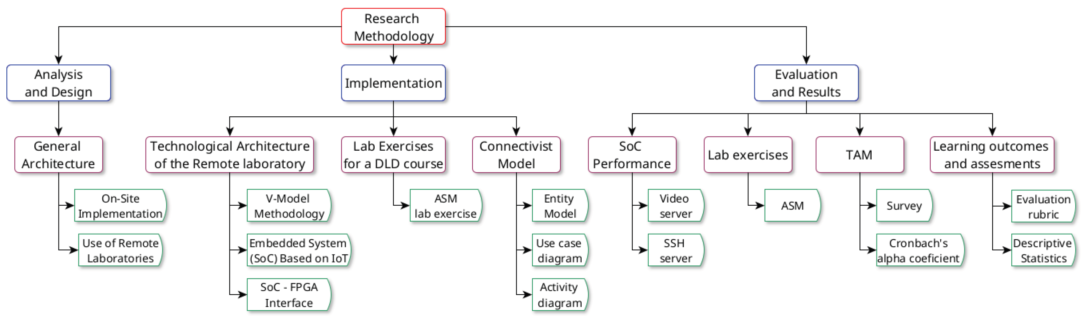
Figure 2.
General Architecture.
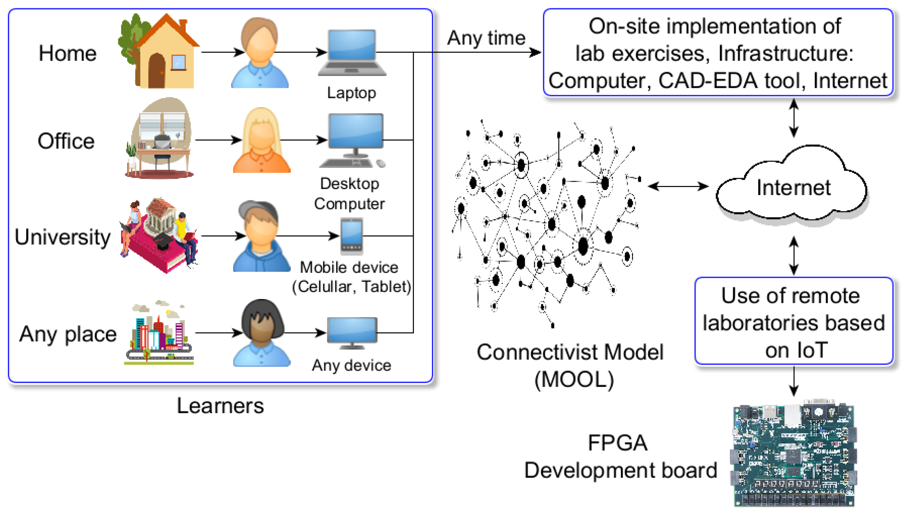
Figure 3.
On-site implementation of lab exercises.
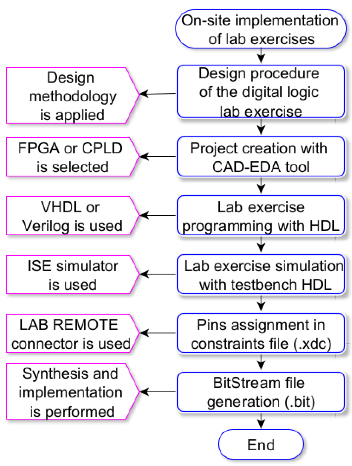
Figure 4.
Use of remote laboratories.
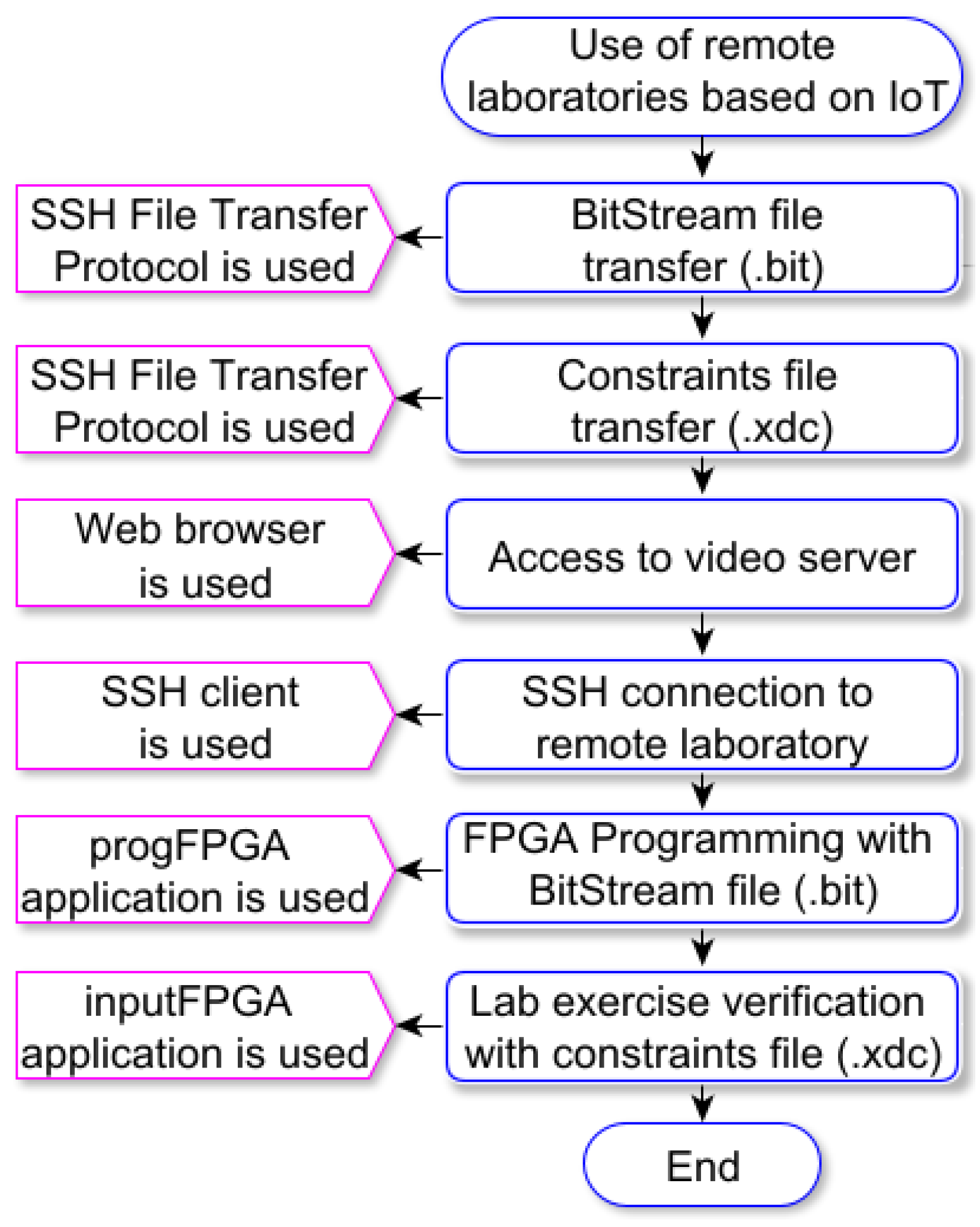
Figure 5.
Technological Architecture of the Remote Laboratory.
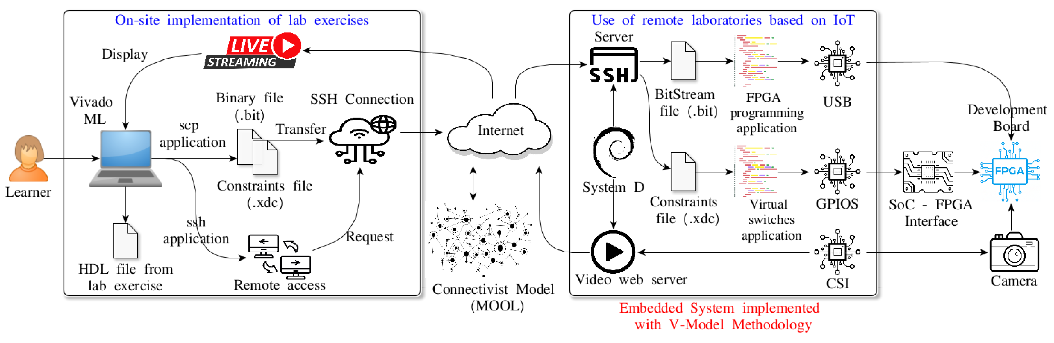
Figure 6.
V-Model Methodology.
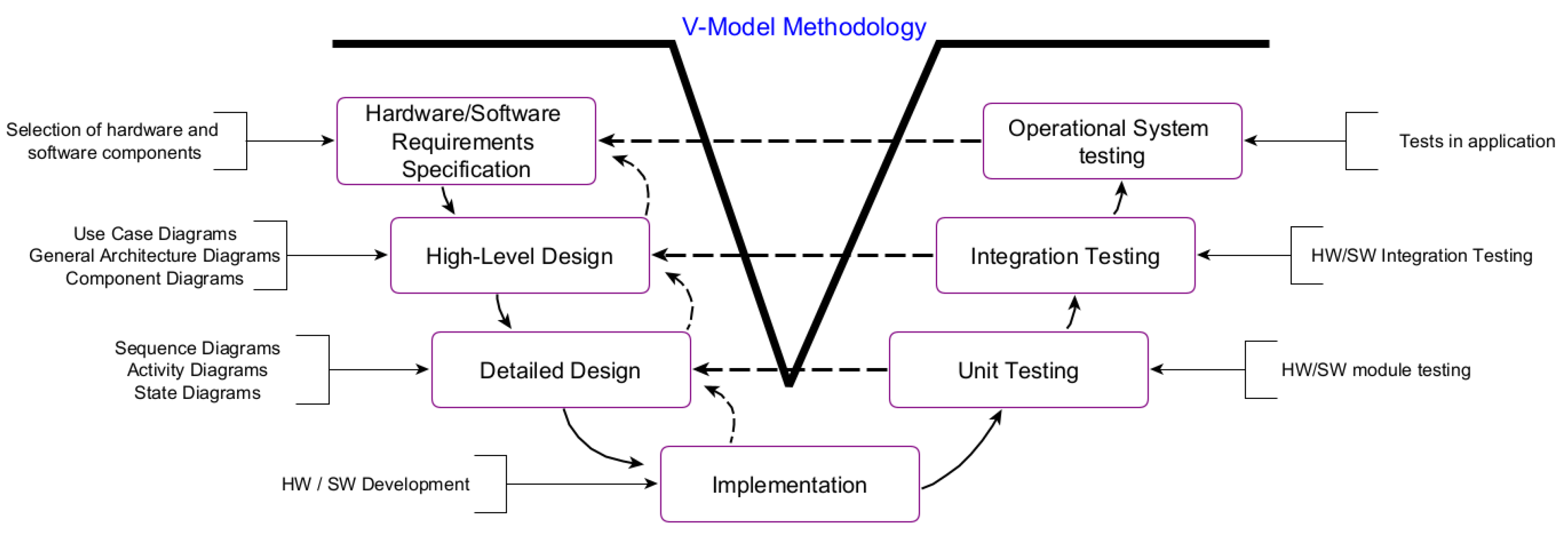
Figure 7.
SoC-FPGA Interface.
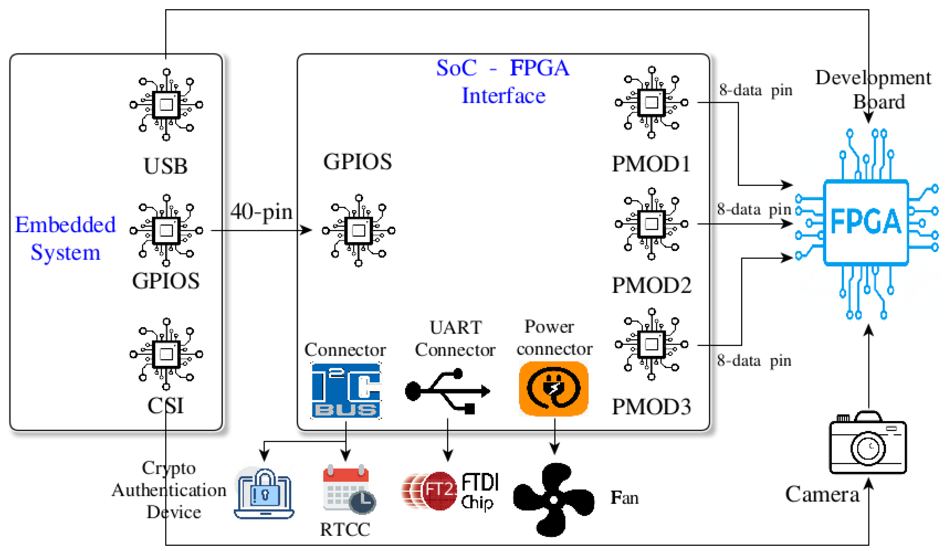
Figure 8.
Algorithm State Machine of the lab exercise.
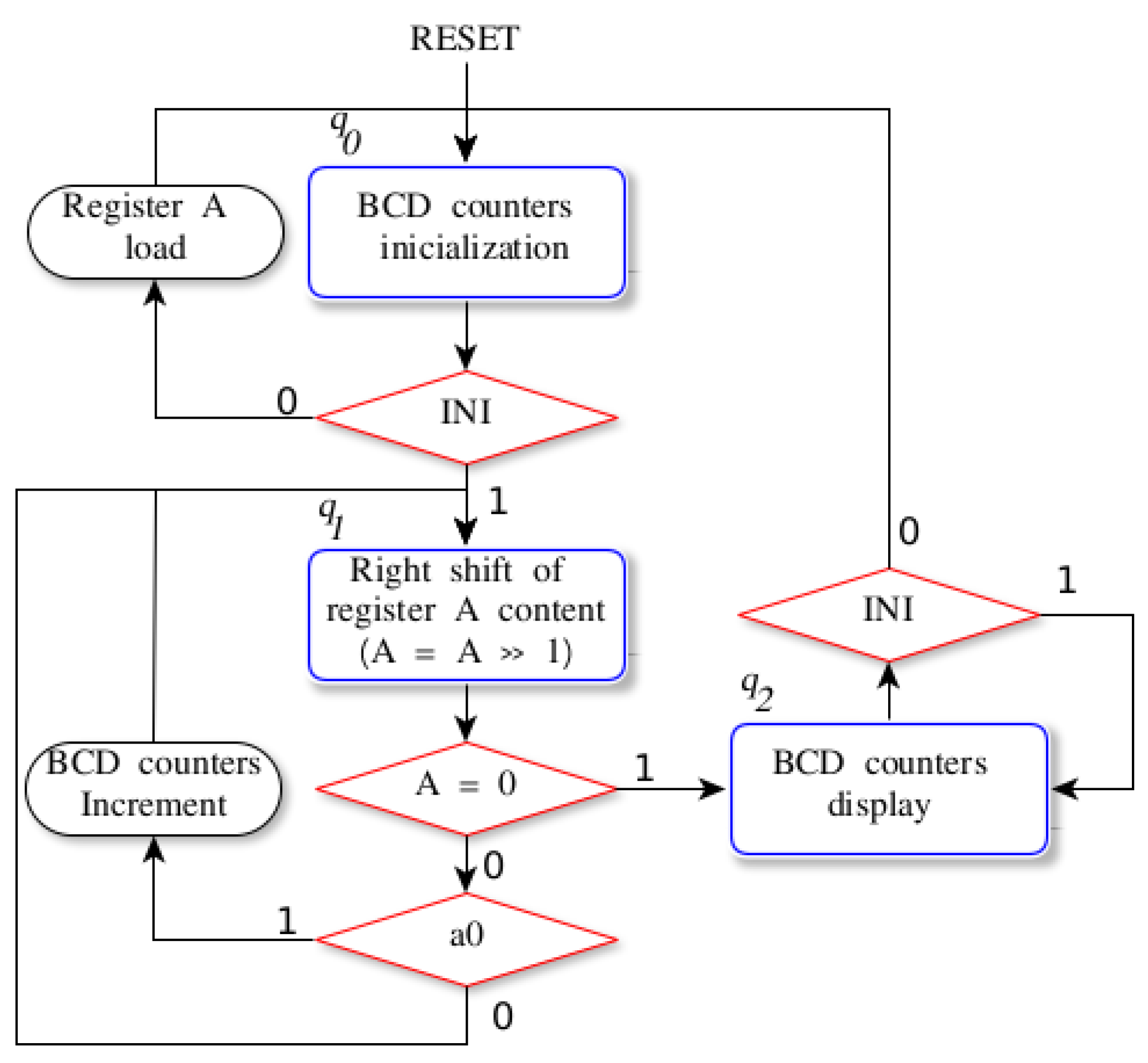
Figure 9.
Microarchitecture of the ASM lab exercise.
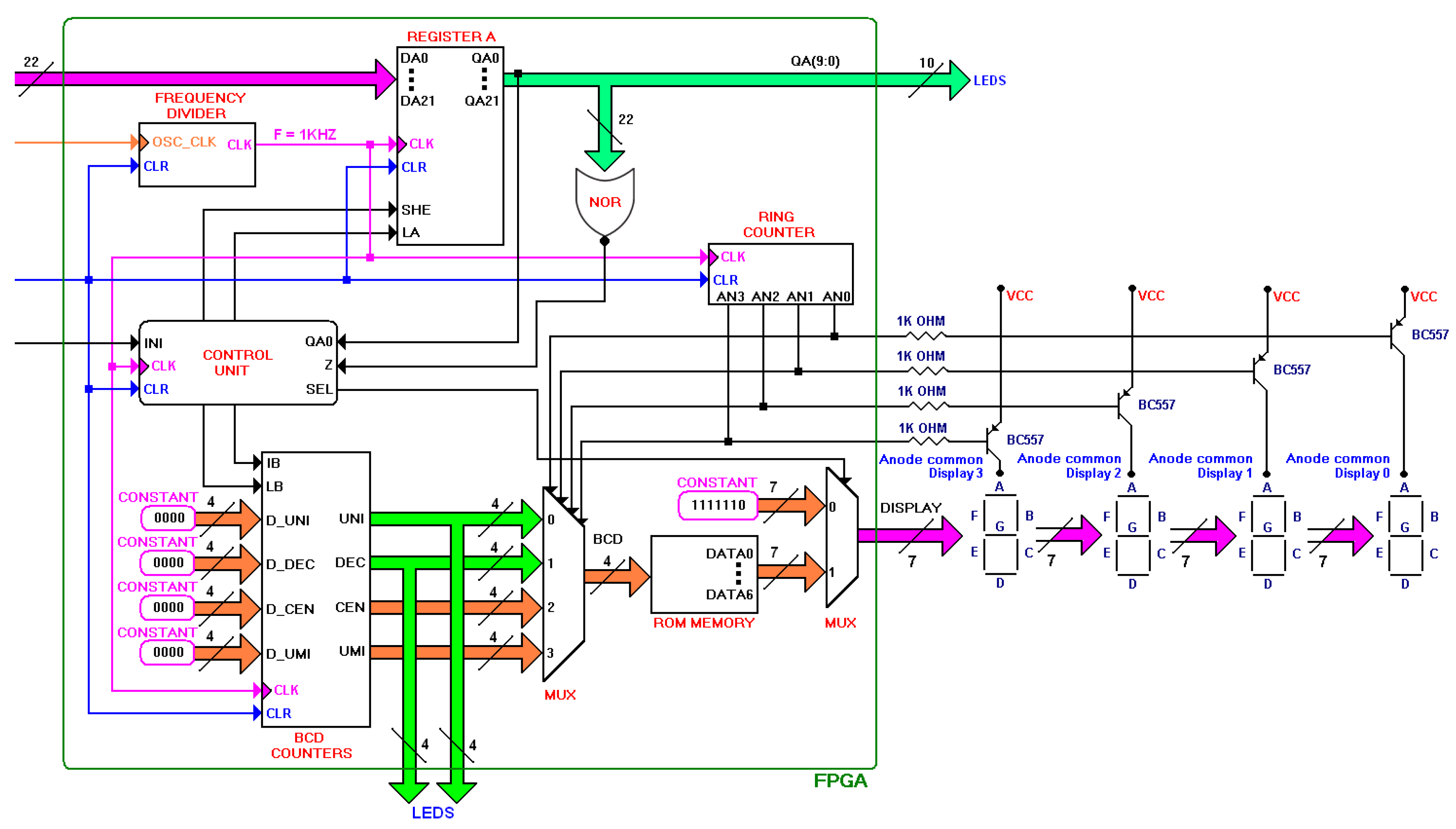
Figure 10.
Algorithm design for BCD counters.
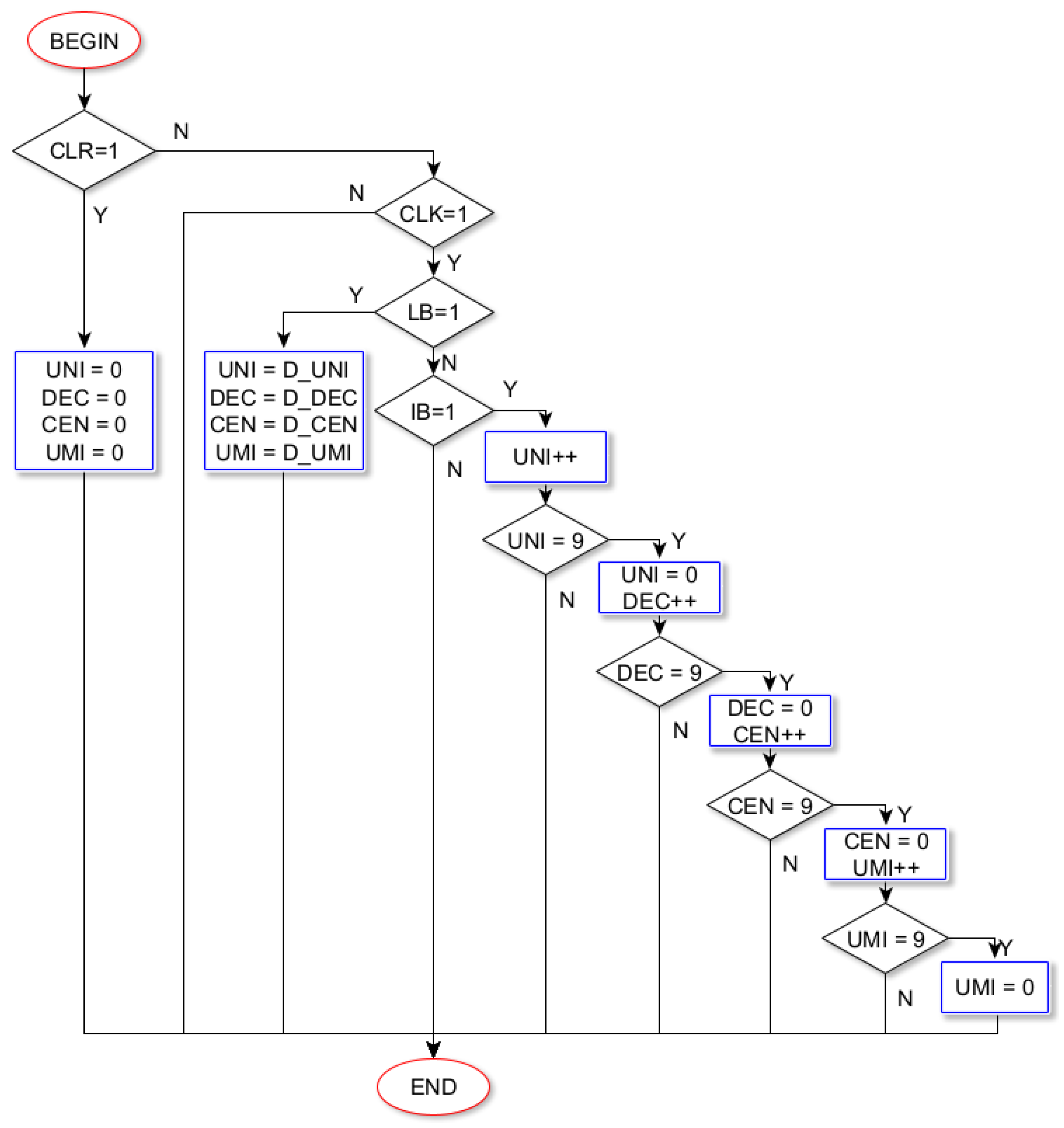
Figure 11.
Automaton of the Control Unit.

Figure 12.
Entity model for the DLD course.
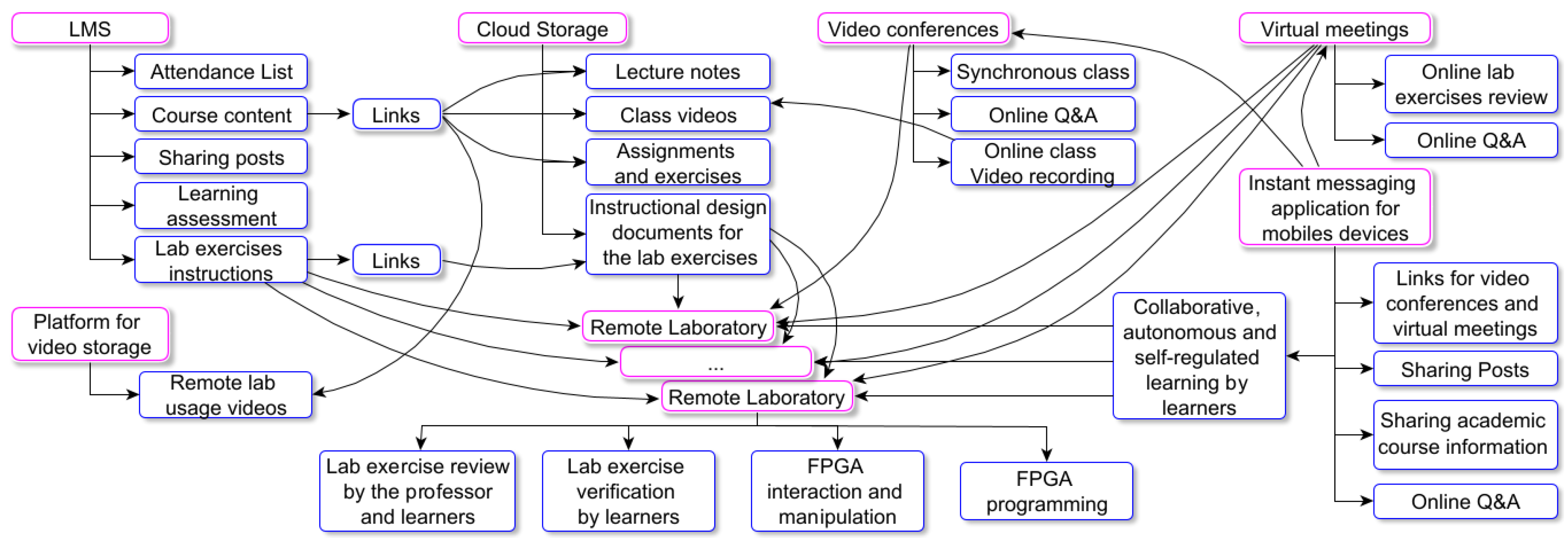
Figure 13.
LMS of the DLD course: (a) Homepage and course content. (b) Explanation of the ASM lab exercise using the Visual Design learning strategy [68]. Within this strategy, the Canva environment [69] and the Lumi software [70] are employed to create interactive H5P components.
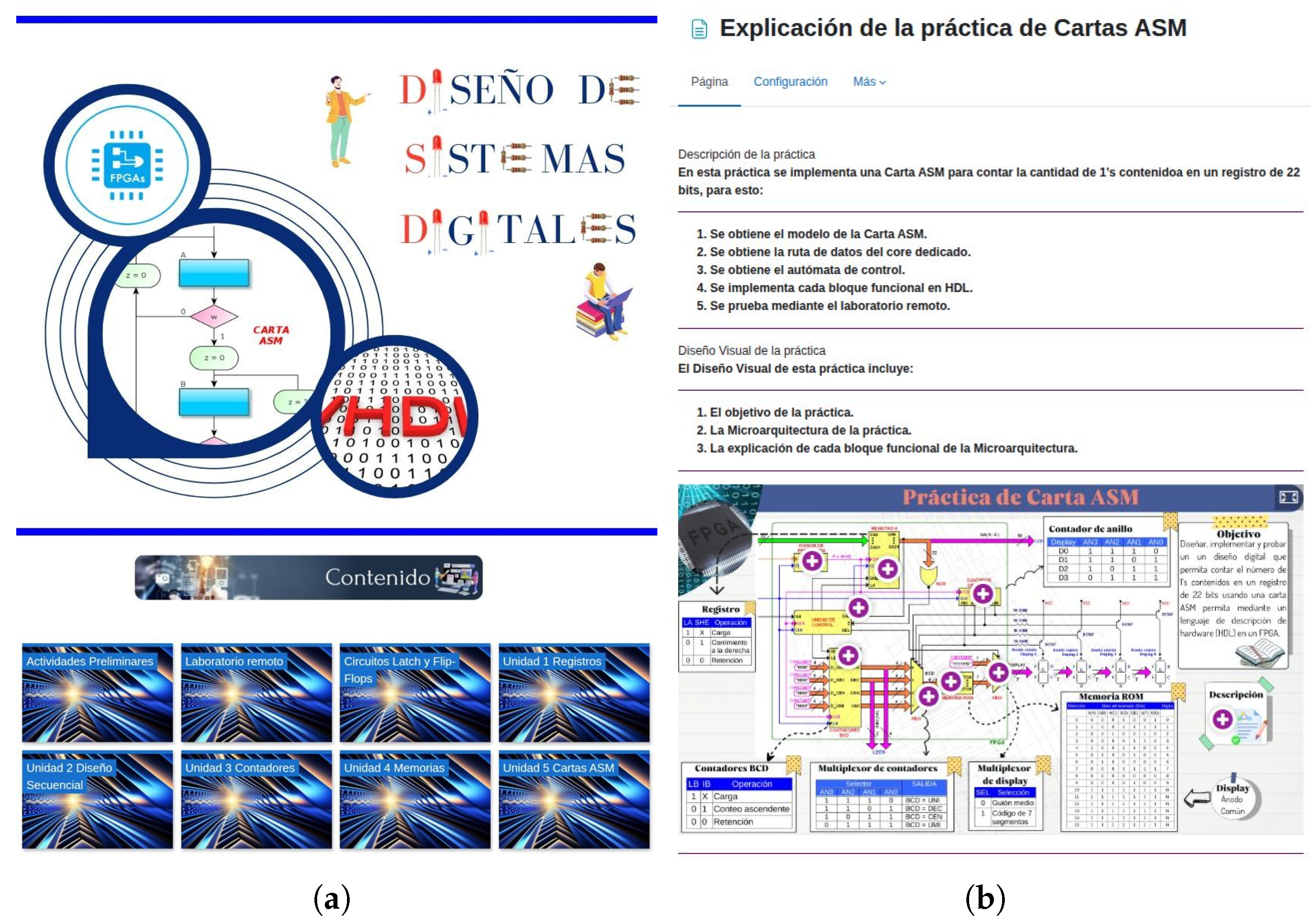
Figure 14.
Use case diagram of the connectivist model.
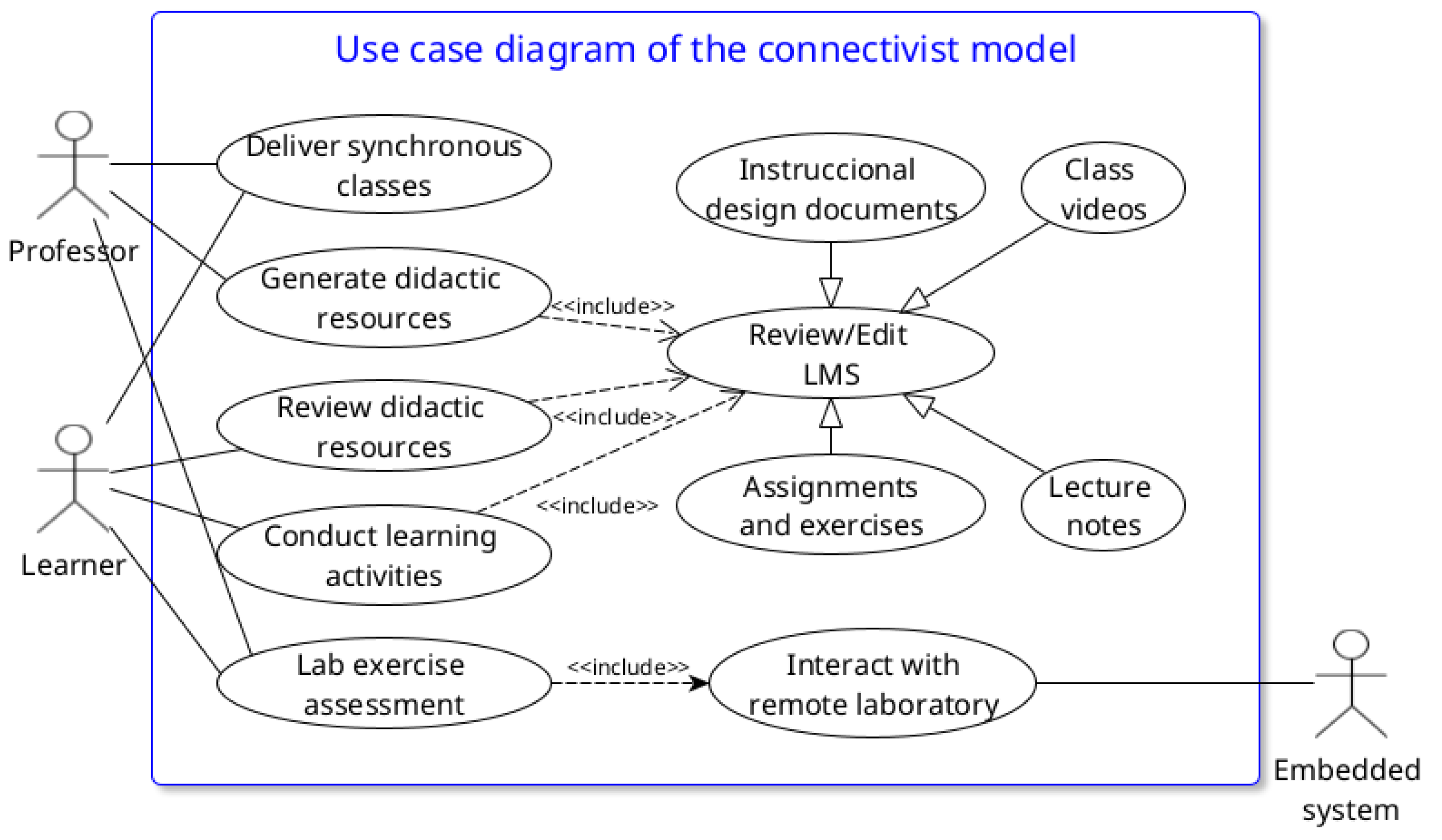
Figure 15.
Activity Diagram of the “Lab Exercise Assessment” use case.
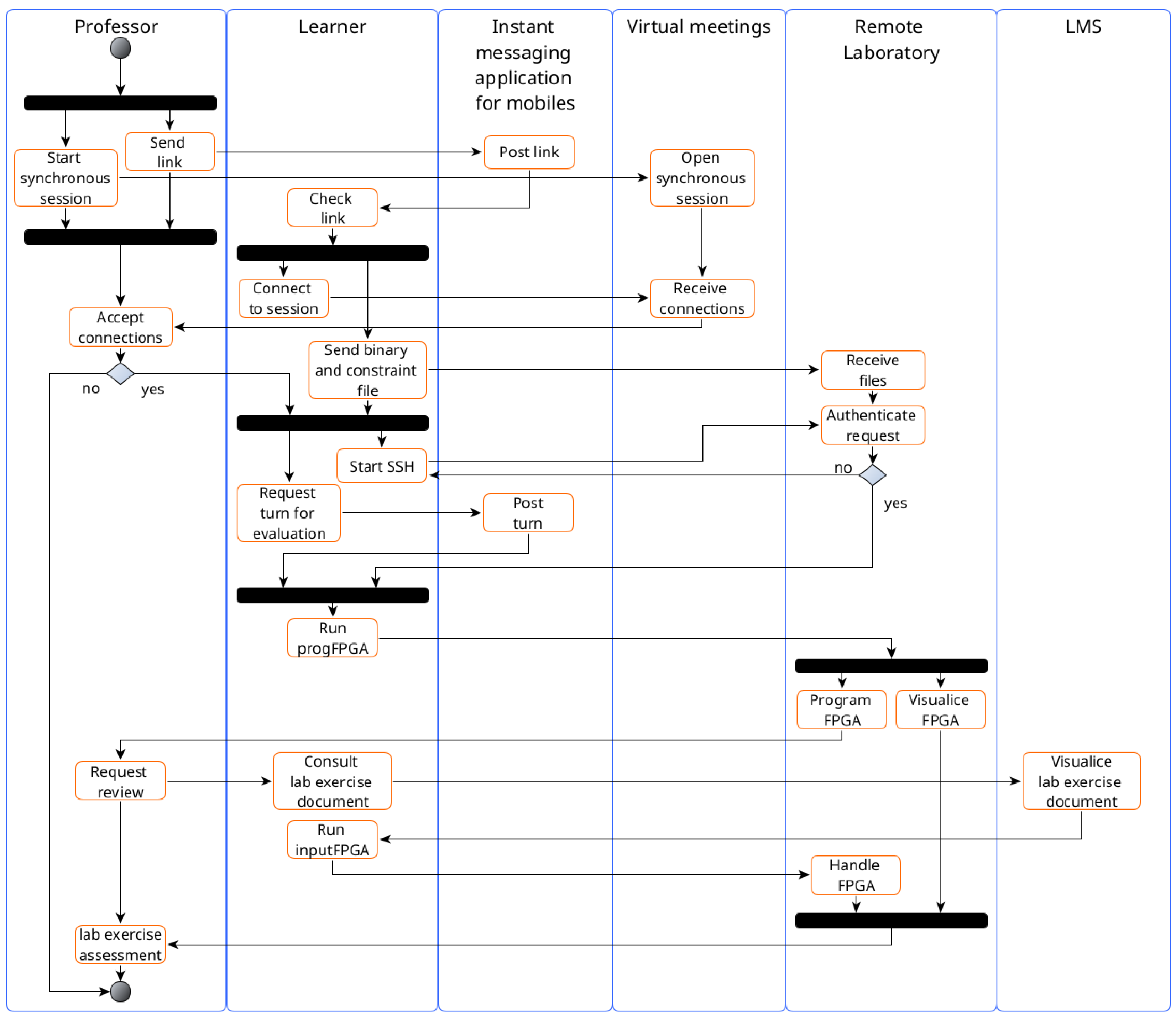
Figure 16.
Physical implementation of the remote laboratory: (a) Complete system consisting of an FPGA development board, camera, SoC-FPGA interface, SoC, FT232 module, power supply, crypto-authentication device, and RTCC. (b) A shelf containing six complete remote laboratory systems.
Figure 16.
Physical implementation of the remote laboratory: (a) Complete system consisting of an FPGA development board, camera, SoC-FPGA interface, SoC, FT232 module, power supply, crypto-authentication device, and RTCC. (b) A shelf containing six complete remote laboratory systems.
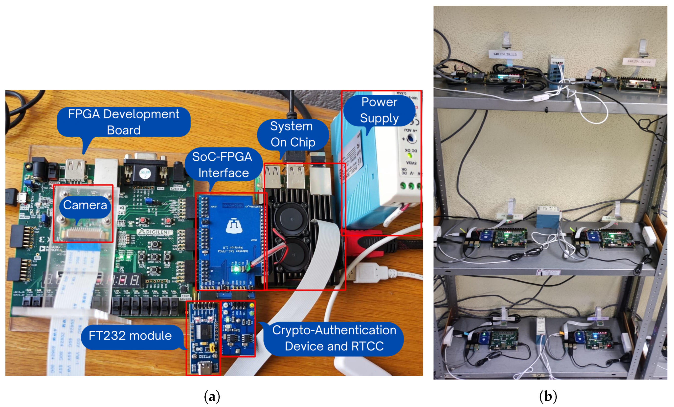
Figure 17.
VHDL implementation of the Control Unit of the ASM lab exercise Microarchitecture.
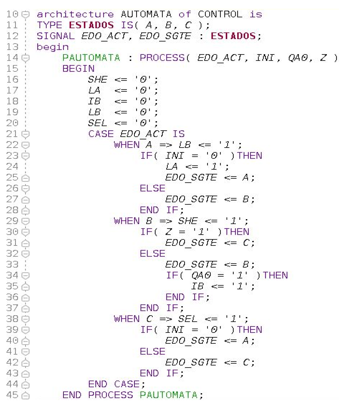
Figure 18.
Testbench simulation of the ASM lab exercise.
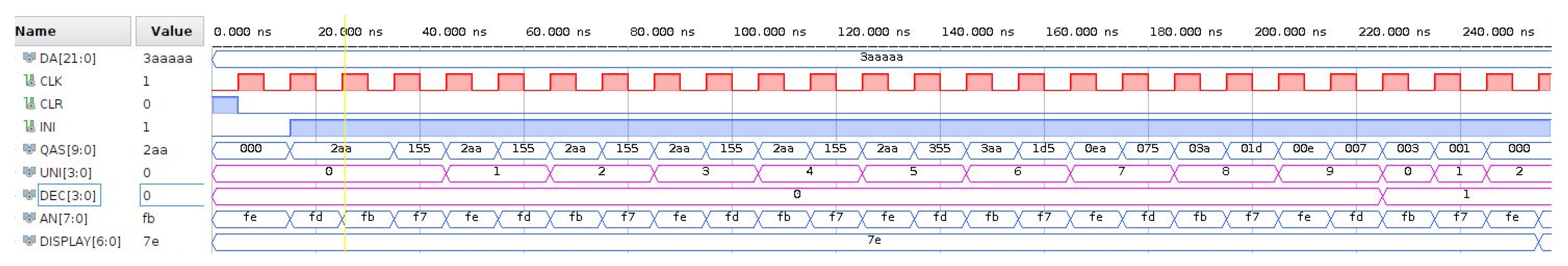
Figure 19.
Functional verification of the ASM lab exercise with the remote laboratory: (a) Input values for the ASM lab exercise using the virtual switches application. (b) Video server result for the ASM lab exercise.
Figure 19.
Functional verification of the ASM lab exercise with the remote laboratory: (a) Input values for the ASM lab exercise using the virtual switches application. (b) Video server result for the ASM lab exercise.
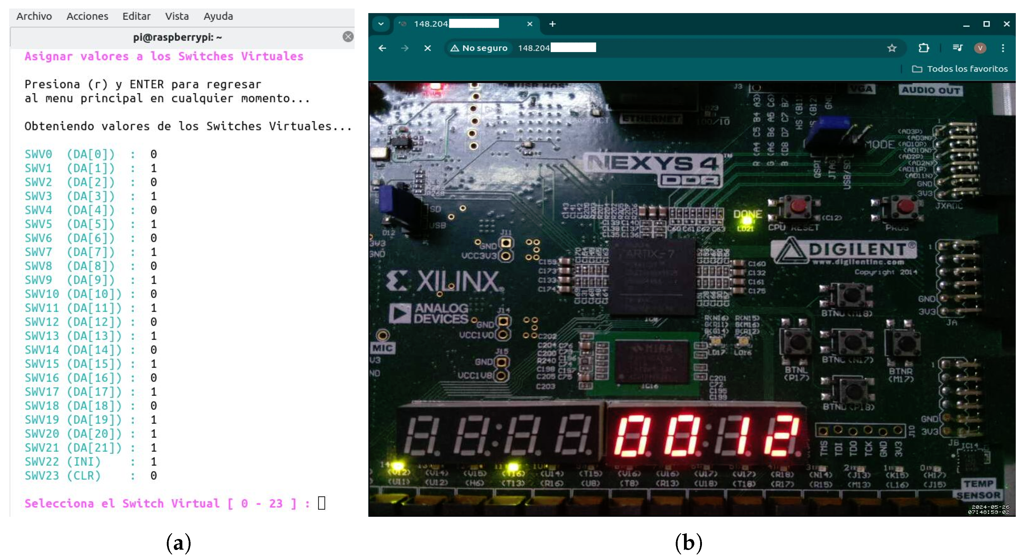
Figure 20.
TAM adapted.
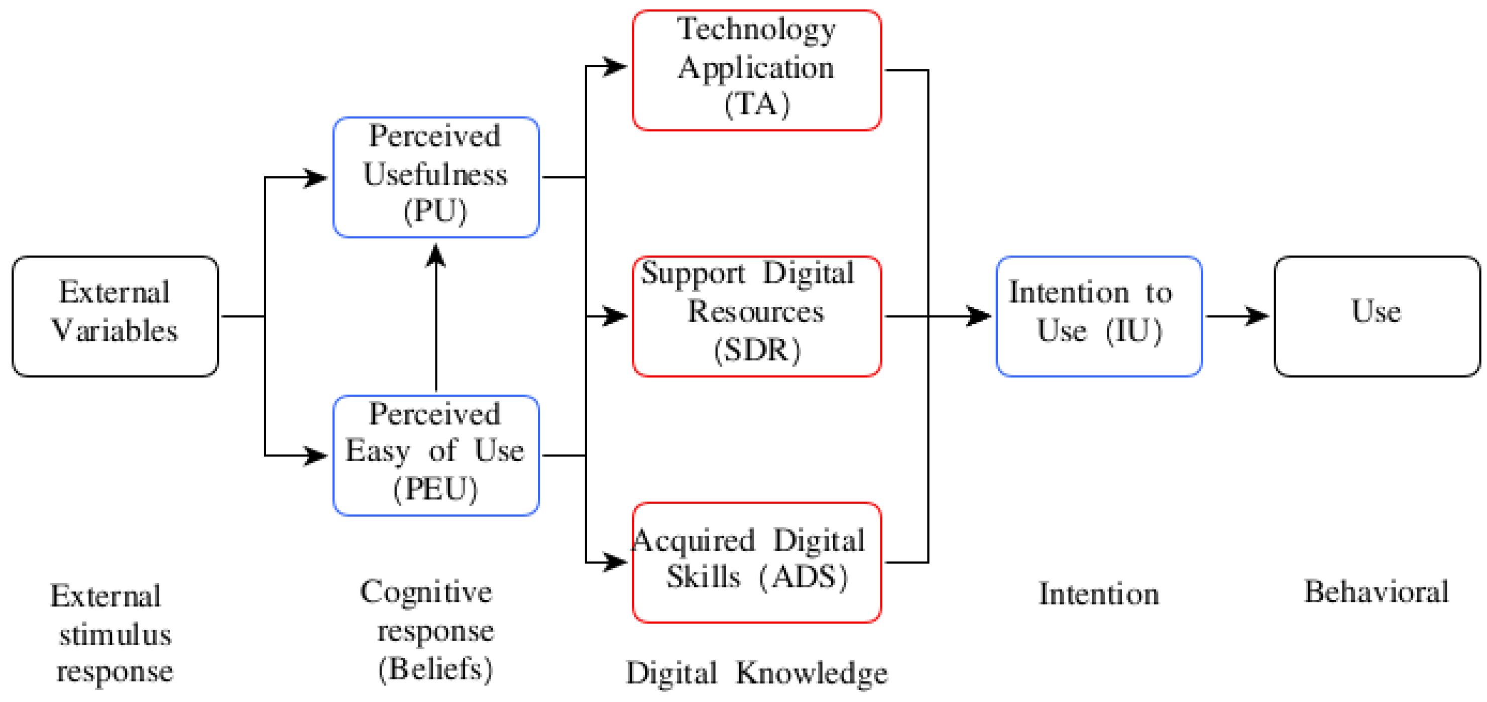

Table 1.
Virtual switches of the LAB REMOTE connector.
| Virtual Sw | FPGA-pin | Virtual Sw | FPGA-pin | Virtual Sw | FPGA-pin |
|---|---|---|---|---|---|
| SWV0 | H14 | SWV8 | G17 | SWV16 | B18 |
| SWV1 | H16 | SWV9 | G18 | SWV17 | A18 |
| SWV2 | G16 | SWV10 | E18 | SWV18 | B16 |
| SWV3 | G13 | SWV11 | F18 | SWV19 | B17 |
| SWV4 | F16 | SWV12 | D18 | SWV20 | A15 |
| SWV5 | F13 | SWV13 | E17 | SWV21 | A16 |
| SWV6 | D14 | SWV14 | C17 | SWV22 | A13 |
| SWV7 | E16 | SWV15 | D17 | SWV23 | A14 |
Table 2.
Lab exercises of DLD course.
| No | Lab exercise title | Course topic |
|---|---|---|
| 1 | Combinational logic | Introduction |
| 2 | Flip-Flops | Latches and Flip-Flops circuits |
| 3 | Registers | Registers: architectures and applications |
| 4 | Sequence detector | Registers applications and Mealy Machine (MyM) |
| 5 | Multiplexed message | Moore Machine (MoM) |
| 6 | Counters | Counters: architectures and applications |
| 7 | Special counters | BCD, Ring and Johnson counters |
| 8 | Sensors | MyM, special counters applications |
| 9 | Algorithmic State Machine (ASM) | Registers, counters and memories applications, and ASM |
Table 3.
CPU performance and memory usage for video server.
| Users | %CPU | %MEM | Mem (MB) | |||
|---|---|---|---|---|---|---|
| Total | Free | Used | Cache | |||
| 0 | 36.6 | 5.2 | 871.7 | 548.0 | 68.7 | 254.4 |
| 1 | 84.8 | 5.2 | 871.7 | 548.2 | 69.0 | 254.4 |
| 2-10 | 85.1 | 5.2 | 871.7 | 548.2 | 69.1 | 254.4 |
Table 4.
SSH server’s Performance.
| User connections | Connections made within time intervals | |
|---|---|---|
| 1s | 3s - 60s | |
| 5 | 5 | 5 |
| 10 | 10 | 10 |
| 15 | 15 | 15 |
| 20-30 | 15 | 19 |
Table 5.
FPGA resources of the ASM lab exercise.
| Resource | Utilization | Available | Utilization(%) |
|---|---|---|---|
| LUT | 65 | 63400 | 0.10 |
| FF | 72 | 126800 | 0.06 |
| IO | 58 | 210 | 27.62 |
| BUFG | 2 | 32 | 6.25 |
Table 6.
FPGA Timing information of the ASM lab exercise.
| Period | Worst Negative Slack | Maximum frequency | Worst Hold Slack |
|---|---|---|---|
| (T) | () | () | () |
| 10 ns | 7.788 ns | 452 MHz | 0.262 ns |
Table 7.
Items for each variable of the TAM.
| Variable | Tag | Item |
|---|---|---|
| Learner | SP1 | Age. |
| profile | SP2 | Gender (Male/Female). |
| PU1 | The remote lab allows learners to gain practical knowledge of the topics covered in the course. | |
| Perceived | PU2 | The remote lab allows learners for performing lab exercises remotely in an innovative way. |
| Usefulness | PU3 | The time allocated for remote lab use is greater than the time allocated for physical lab use. |
| PU4 | Interaction with remote lab enhances the understanding of each course topic more than using only simulators. | |
| PU5 | The remote lab access can be done from anywhere and at any time. | |
| PEU1 | The application for programming the BitStream file onto the FPGA is easy to use. | |
| Perceived | PEU2 | The application for interacting with the remote lab connector allows for easy input value assignment to test the lab exercises. |
| Easy of use | PEU3 | The video server allows the results of the lab exercises to be displayed with low latency (in seconds). |
| PEU4 | The live video stream allows the results of the lab exercises to be viewed clearly and sharply. | |
| PEU5 | Assigning terminals on the REMOTE LAB connector using the constraints file is easy to do. | |
| Technology | TA1 | The use of the remote lab allows learners to acquire and apply knowledge from the Computer Networks course. |
| Application | TA2 | The use of the remote lab allows learners to acquire and apply knowledge from the Operating Systems course. |
| Support | SDR1 | The operation video of the remote lab using Putty and WinSCP is useful for learning how to use it on the Windows operating system. |
| Digital | SDR2 | The user manual of the remote lab is useful for learning how to use it. |
| Resources | SDR3 | The support material provided is useful for operating the remote lab. |
| Acquired Digital Skills | ADS1 | The Vivado CAD-EDA tool allows learners to develop and simulate HDL programs of each course lab exercise |
| Intention | IU1 | Would you like to continue using the remote lab in future courses?. |
| to Use | IU2 | Would you like to continue using the remote lab for development and learning of personal and academic projects?. |
Table 8.
Survey results.
| Variable | Tag | (n) | (a) | (ta) |
|---|---|---|---|---|
| PU1 | 100% | |||
| Perceived | PU2 | 100% | ||
| Usefulness | PU3 | 3.6% | 3.6% | 92.9% |
| PU4 | 3.6% | 96.4% | ||
| PU5 | 7.1% | 92.9% | ||
| PEU1 | 3.6% | 96.4% | ||
| Perceived | PEU2 | 3.6% | 3.6% | 92.9% |
| Easy of use | PEU3 | 7.1% | 92.9% | |
| PEU4 | 10.7% | 89.3% | ||
| PEU5 | 3.6% | 96.4% | ||
| Technology | TA1 | 10.7% | 89.3% | |
| Application | TA2 | 3.6% | 7.1% | 89.3% |
| Support | SDR1 | 7.1% | 92.9% | |
| Digital | SDR2 | 100% | ||
| Resources | SDR3 | 100% | ||
| Acquired | ADS1 | 14.3% | 85.7% | |
| Digital Skills | ||||
| Intention | IU1 | 10.7% | 89.3% | |
| to use | IU2 | 14.3% | 85.7% |
Table 9.
Evaluation rubric for the DLD Course.
| Specific indicators | Criteria | Grade | ||
|---|---|---|---|---|
| 80-100 | 60-79 | 0-59 | ||
| Ability to represent a problem using a model based on Mealy Machine, Moore Machine and Algorithmic State Machine. | a. Problem analysis, determination of inputs and outputs | a | a | a |
| b. Model selection and design | b | b | ||
| c. Model states reduction | c | |||
| d. Correct code assignment | d | d | d | |
| e. State table generation | e | e | e | |
| Ability to apply the digital logic design methodology and obtain a digital circuit. | f. Correct assignment of values to the control signals of the chosen FF | f | f | |
| g. Correct use of minimization method | g | |||
| h. Correct equations | h | |||
| i. Programming using an HDL | i | i | i | |
| Ability to implement the digital circuit using a model based on Mealy Machine, MooreHDL and a CAD-EDA tool. | j. Using a simulator with a Test Bench file | j | j | |
| k. Pin assignment, constraints and BitStream file generation | k | |||
| Ability to test lab exercises | l. File transfer to the server | l | l | l |
| using the remote laboratory. | m. Remote access to the server | m | m | m |
| n. FPGA programming | n | n | ||
| o. Manipulation of lab exercise inputs | o | |||
| p. Verification of lab exercise results | p | |||
| Ability to write technical reports using the transmedia narrative strategy. | q. Writing the report using digital media | q | q | q |
| r. Explanation of lab exercise testing | r | r | ||
| s. Explanation of results and conclusions | s | s | ||
| t. Inclusion of appropriate references according to the digital media | t | |||
Table 10.
Statistic descriptive results of the DLD courses.
| Year | Group | Mean | Standard deviation | Variance | CV |
|---|---|---|---|---|---|
| 2017 | 2CM1 | 7.951 | 1.1905 | 1.417 | 14.97 |
| 2018 | 2CM10 | 7.075 | 1.967 | 3.871 | 27.8 |
| 2019 | 2CM7 | 8.408 | 1.978 | 3.916 | 23.53 |
| 2021 | 2CM16 | 9.777 | 0.634 | 0.403 | 6.49 |
Table 11.
Differences between laboratory modalities.
| Aspects to consider | In-person modality | Remote modality |
|---|---|---|
| Usage time (Availability) | Very limited, only 1.5 hours per week | Continuous time, 24/7 access |
| Accessibility | Only learners belonging to the academic unit | Any learner with an assigned account |
| Learner location | The learner must attend the academic unit | Anywhere in the world |
| Laboratory infrastructure | Personal computer, CAD-EDA tool and development board | Embedded system, internet connection and development board |
| Learner infrastructure | None | PC, CAD-EDA tool and Internet connection |
| Lab physical space | Lab classroom dimensions determined by educational institution | 30cmx20cmx20cm dimensions for each remote lab |
| Educational staff | Staff is required to provide access, materials, and perform reviews | No staff required |
| Learners who interact during the review | Limited to team members learners | All the learners in the class |
Table 12.
Comparison with the literature review.
| Paper | Technological Architecture | Learning Theory | Software Application | Measuring Instrument | Lab exercises sequence | Learning outcomes |
|---|---|---|---|---|---|---|
| Paper proposed | Server in RaspberryPi3 SoC, video from the Camera Module V2, Nexys 4 with Xilinx FPGA | Connectivism | Visual Shell Applications for FPGA programming and interaction with virtual switches | Likert scale survey with TAM and Alfa’s Cronbach coefficient | Nine lab exercises | Evaluation rubric, descriptive statistics |
| [29] | Server in RaspberryPi4 SoC, without video, Nexys3 with Xilinx FPGA | None | Web Application | Likert scale survey without model | Four Projects | None |
| [31] | Server in PC, video from WebCam, Spartan-3E with Xilinx FPGA | None | Web Application | Without survey and model | Two Projects without interaction | None |
| [36] | Server in RaspberryPi3 SoC, video from WebCam, DE2-115 with Altera FPGA | None | Web Application | Likert scale survey without model | Without lab exercises | None |
| [32] | Cloud Server, host computer, without video, Spartan 6 FPGA | None | Web Application | Without survey and model | Nine projects | None |
| [33] | Server in Zynq-7 SoC, without video, Artix-7 with Xilinx FPGA | None | Web Application | Without survey and model | MIPS32 processor | None |
| [34] | Host Computer, without video, Cyclone II with Altera FPGA | None | Visual Interface | Without survey and model | Without lab exercises | None |
| [30,35,38,39] | Host Computer, with video, FPGA Board | None | Web application | Without survey and model | Without lab exercises | None |
| [40] | RaspberryPi5, with video, Basys 3 FPGA | None | Web application | With survey without model | 3 lab exercises | None |
| [41] | MPSoC-FPGA, without video | None | Jupyter Hub Interface | Without survey and model | 5 lab exercises | None |
Disclaimer/Publisher’s Note: The statements, opinions and data contained in all publications are solely those of the individual author(s) and contributor(s) and not of MDPI and/or the editor(s). MDPI and/or the editor(s) disclaim responsibility for any injury to people or property resulting from any ideas, methods, instructions or products referred to in the content. |
© 2025 by the authors. Licensee MDPI, Basel, Switzerland. This article is an open access article distributed under the terms and conditions of the Creative Commons Attribution (CC BY) license (http://creativecommons.org/licenses/by/4.0/).
Copyright: This open access article is published under a Creative Commons CC BY 4.0 license, which permit the free download, distribution, and reuse, provided that the author and preprint are cited in any reuse.


