Submitted:
29 November 2025
Posted:
02 December 2025
You are already at the latest version
Abstract
Industrial heritage movable assets, particularly the traditional machining tools used in manufacturing processes, are facing an increasing risk of disappearing due to the con-tinuous advance of technology. Innovations in industry have progressively displaced many of these manual tools, making them obsolete or irrelevant in current manufacturing processes, remaining only for artisanal work. In this context, manual vertical drilling presses, which have played a crucial role in manufacturing for decades, are being dis-placed by more advanced machining tools, which incorporates, technologies such as Computer Numerical Control (CNC). This work focuses on the development of a manual vertical drill press digital model, in order to virtually recreate its operation and structure. The software used to develop the model was SolidWorks. This model aims not only to preserve a historically significant machine but also to serve as an educational resource, illustrating drilling operations before modern technologies emerged. Reconstructing them in 3D enhances the study and understanding of their mechanics and utility, ensuring access to technical knowledge and preserving their legacy in a digitalized world.
Keywords:
digitalization
; drilling
; machine tool
; industrial heritage
1. Introduction
The importance of virtual simulations in teaching has increased over the years and is increasingly recognized and valued in the educational field [1]. These tools are considered technological resources capable of offering a wide variety of benefits and opportunities that enrich teaching. Access to realistic studies is improved, since, in the face of potential difficulties in gaining direct experience with industrial equipment, students can enter detailed virtual environments to explore complex machines or scientific phenomena by simulating experiments, observing internal processes, or visualizing natural events.
Furthermore, virtual simulations support inquiry-based learning, allowing students to directly interact with engineering principles through active experimentation. Rather than passively absorbing lessons on kinematic chains or torque transmission, students manipulate variables such as pulley ratios and observe the resulting mechanical behaviors in real time through a screen. This hands-on approach allows them to witness cause-and-effect relationships, interpret simulation outputs, and iteratively adjust their models, thereby developing critical thinking and problem-solving skills. Particularly when exploring failure modes, as these environments prove invaluable in practice, students can challenge conditions such as misaligned clamps, overloaded bearings, or insufficient lubrication to visualize the mechanics of failure and internalize good maintenance practices long before handling physical equipment [1,2].
Interactive and participatory learning is enhanced through virtual recreations, increasing student motivation and engagement. Furthermore, flexibility and adaptability allow students to access the material individually, at any time, and from any location. Risk-free experimentation is another key aspect, as although real machines incorporate safety mechanisms, an inexperienced person can still face danger; virtual models completely eliminate that risk. Another important factor is that these tools allow for continuous updating and adaptation to technological advances [3], ensuring that the educational content remains relevant. In universities, engineering and design curricula have long grappled with the limitations of physical workshops: expensive equipment, safety concerns, limited machine availability, and the costs of inputs such as tools, lubricants, and materials [1,2]. Virtual models of machine tools such as lathes, milling machines, drill presses, or hydraulic presses overcome these barriers by offering students high-fidelity, interactive simulations accessible from laptops, tablets, or virtual reality labs. A mechanical engineering student can virtually mount a cutting tool, adjust spindle speed, vary feed rate, and observe chip formation, surface finish, and stresses on the tool, all without risk of injury or damage to the machine. By repeating experiments at no additional cost and instantly visualizing internal forces, temperature distributions, and vibration modes, students gain a deep and intuitive understanding of machining principles that complements the theoretical content [4,5].
The educational, cultural, and economic benefits of virtual recreations are mutually reinforcing. Universities reduce investment and operating costs by moving part of their laboratory instruction to virtual environments; museums expand their reach and impact without putting fragile artifacts at risk; researchers gain a non-destructive testing bench for engineering analysis [6]. Virtual laboratories do not consume cutting fluids, generate metal chips, or require safety shutdowns. This supports sustainability goals while protecting institutional budgets.
By achieving these goals, the work will provide an effective and innovative teaching tool, allowing educators and students to acquire practical knowledge about the fundamentals of machine tools. In turn, this contributes to safeguarding industrial heritage, promoting interdisciplinary collaboration, and preparing future professionals to innovate responsibly in a world where the interaction between physical artifacts and digital representations is becoming increasingly important in education, culture, and research. The integration of virtual recreations into both university education and museum practice is redefining the way industrial heritage is taught, learned, and preserved [7].
In museum settings, virtual recreations transform static exhibits into living experiences. An early 20th-century column drill, motionless behind a display case, becomes comprehensible when visitors use an augmented reality application [8,9] or a touchscreen to animate its moving mechanism, view exploded diagrams, and even “operate” the machine under guided supervision. This interactivity positively engages diverse audiences such as students, families, and apprentices, turning observation into participation. Potential uses in games (gamification) attract younger visitors, who are more accustomed to digital interfaces, prolonging their stay and deepening their connection with industrial history [10]. As the debate about the role of digital technologies in museums and cultural institutions continues, the concept of “augmented realism” is closely linked to emerging technologies that seek to minimize the perceived gap between the viewer and the experience itself [11]. From this perspective, it is anticipated that digital tools will be seamlessly and deeply integrated into the museum environment, eventually eliminating any distracting effects they may initially have caused [12].
Among the various heritage categories, this paper focuses on industrial heritage. This specific type of heritage, internationally recognized as a distinct modality, possesses unique characteristics that differentiate it from other forms of heritage. For example, many of the movable and immovable assets classified as industrial heritage are relatively recent compared to other categories [13]. Furthermore, rapid technological advances have continuously transformed industrial activity, leaving a tangible record of these changes in remarkably short periods [14]. Historical and cultural heritage represents an expression and testimony of collective and social identity. Therefore, it is crucial to promote studies that examine this heritage, analyzing its historical and cultural dimensions. This approach aims to preserve and transmit valuable knowledge that, if not documented, risks being lost over time [15].
Industrial transformation also gave rise to significant social changes and movements, which are closely related. These aspects increase interest in the study of industrial heritage, allowing us to connect machinery and equipment with their historical context. This includes the analysis of the technology used, the social dynamics, and the corresponding historical period. In this context, the unique characteristics of industrial heritage make it a particularly attractive subject of study compared to other heritage categories [16,17].
The digital realm has great potential to revolutionize how individuals interact with heritage in its broadest sense. This topic has been a central focus of academic debates and cultural initiatives. On the one hand, the internet has been highlighted as a powerful platform for raising awareness of the heritage sector, fostering greater interest and encouraging in-person visits, especially to museums. On the other hand, digital environments have been proposed as dynamic and interactive spaces that allow for two-way communication with cultural heritage, complementing and enriching the physical experience. A key question for researchers and managers involved in the study or management of heritage, history, and its cultural significance is to identify the intrinsic value that interaction with digital tools brings to these experiences [18].
Virtual heritage also democratizes access [19]. A specialized machine tool, located in a technical museum in another country or region, can be shared globally through web portals or virtual reality platforms [20]. Distance learning students, researchers, and enthusiasts from anywhere in the world gain 24/7 access to the same interactive model, equalizing educational opportunities and fostering international collaboration. Instructors integrate these resources into online courses, enabling hybrid and fully remote programs that maintain practical rigor through virtual laboratories. The selection of a machine or facility for 3D modeling will be based on several criteria, such as its educational relevance, historical and cultural significance, historic location [21,22], advances in energy efficiency [23], or its association with a recognized figure, which may have made it an iconic object [24]. These three-dimensional representations provide heritage managers with a valuable tool for developing sustainable and economically viable reuse strategies for the industrial heritage under consideration. The introduction of computer numerical control marked a milestone in industrial automation, but also represents a threat to the recognition and preservation of the tools that laid the foundations of modern manufacturing [25].
Digital modeling has emerged as a valuable solution for preserving the legacy of these industrial machines. The ability to create accurate virtual recreations of historic machines allows not only to preserve their physical appearance but also to document their operating principles and their role in the evolution of engineering and manufacturing [26]. The study of the manufacturing industry has greatly benefited from advances in current 3D design software, which allows remote analysis of the mechanisms inherent in machinery. From a research and preservation perspective, virtual recreations act as dynamic archives. Detailed 3D scans, combined with metadata (date of manufacture, material properties, maintenance records) and sensors, create a digital twin that can be analyzed to verify its structural integrity, simulated under different loading conditions, or tested for energy efficiency improvements prior to any intervention on the machine itself [27]. Heritage managers use workflows based on building information models to plan the adaptive reuse of industrial sites, exploring virtual factory layouts, assessing material deterioration, and visualizing new architectural works without compromising historical authenticity [28].
This work seeks to apply one of these tools to create a three-dimensional model of a manual drill press. Therefore, the main objective of this study is to understand and analyze the operation of a drill press by creating a virtual recreation. This recreation aims to virtually create the parts that make up this machine tool. In this way, a deeper understanding of this machine tool can be achieved without the need for its physical presence. Drill presses are widely used in industry to perform precise drilling operations in various solid materials, including metals, wood, and plastics. These machines possess distinctive features that make them highly effective for specific applications. Some of their notable qualities include accuracy, drilling capacity, control and adjustability, safety, and versatility.
2. Drill Press Identification
The company Erlo S.A. was founded in Spain in 1961 and has specialized in manufacturing high-quality drills, tapping machines, and machining centers. Its range of column drills has been widely used in the mechanical, metallurgical, and manufacturing industries. The CR-18 model, Figure 1, is a manually operated column drill designed for precision work in workshops and industrial environments. The digitized drill press model dates back to the 1990s, although its original design is older. Known for its robustness, reliability, and precision, the CR-18 has been extensively used across various industrial sectors. Over time, drill designs have evolved to incorporate automated controls and CNC systems. However, the CR-18 remains highly valued in environments where precise manual control and durability are essential.
The CR-18 is a manually fed column drill, suitable for machining metal, plastic, and other materials. It has a drilling capacity of up to 18 mm in steel and features a manual feed with a belt-driven transmission, allowing easy speed adjustment depending on the material. To ensure structural stability, it has a 100 mm column diameter and can accommodate workpieces with a 250 mm spindle-to-column distance.
The worktable is height-adjustable, and the spindle speed can be fine-tuned, making it adaptable for different materials. It has a maximum drilling depth of 120 mm, allowing for deep drilling operations. The motor power is 500 Watts, and its weight of approximately 280 kg ensures stability and precision during operation. Additionally, its compact dimensions (655 × 400 × 1900 mm) make it well-suited for industrial workshops.
Machines like the Erlo CR-18 are considered part of industrial heritage for several reasons:
• Historical and technological significance: They mark a milestone in the evolution of machining and industrial production.
• Role in manufacturing: These machines were fundamental in workshops and factories, playing a crucial role in producing mechanical components.
• Durability and design: Built to last, many of these machines are still in operation decades after their manufacture.
• Engineering evolution: They demonstrate the technological shift from manual operation to automation and CNC (computer numerical control).
Preserving such machines allows us to study the history of engineering, understand past production methods, and appreciate the impact of industrialization on society. The Erlo CR-18 stands as a classic column drill, renowned for its reliable design and widespread use in metalworking industries and machine shops. Its recognition as industrial heritage stems from its historical and technological significance, representing a key stage in the development of mechanical tools over time. Materials
3. Results
3.1. Drill press components modeling
To accomplish this design, a structured set of specific objectives has been defined. The process begins with the modeling of the individual components of the drilling press using the advanced three-dimensional design and simulation tools available in the SolidWorks software suite. This includes both external elements and internal mechanisms, such as housings and transmission systems. Common features in SolidWorks used for this purpose include extruded boss base, revolved boss base, extruded cut, and the hole-wizard tool.
Once all components are modeled, the next phase involves creating the full assembly in SolidWorks. This step consists of integrating the individual parts by defining appropriate positional relationships, based on the type of joint required for each connection. SolidWorks, developed by Dassault Systèmes, stands out as a comprehensive and versatile 3D CAD (Computer-Aided Design) platform that supports the entire product development cycle. It enables the creation of detailed 3D parts, assemblies, and 2D drawings, while also incorporating powerful features such as finite element analysis, simulation, technical documentation, and product data management.
Its wide range of functions makes SolidWorks one of the most widely used applications across various engineering fields, including aerospace, mechanical, electronic, and biomedical engineering. Its advanced capabilities for modeling complex geometries, seamless integration with other design and analysis systems, and user-friendly interface have made it the preferred choice for many professionals. As a result, SolidWorks contributes significantly to improving the quality and efficiency of engineering design processes by saving time and reducing costs.
To create the virtual recreation of the drill press, the first step was to visit the workshop to take precise measurements of its components. The necessary parts were disassembled, and measurements were taken using a caliper, along with a two-contact external micrometer capable of readings with an accuracy of up to hundredths of a millimeter (0.01 mm). For angle measurements, a goniometer with a division value of five minutes (5’) was used. Each measurement was repeated three times to ensure accuracy. Once all the dimensions of the machine were recorded, the individual parts were modeled and subsequently assembled to reconstruct the complete vertical drill press.
Several components modeled in SolidWorks will be presented, along with the final assembly of the drilling press. The worktable with its clamp (Figure 2) serves as the primary surface responsible for securely holding the parts to be drilled. Made from milled cast iron, the table provides a stable foundation beneath the drill bit. It is mounted to the column using a yoke that permits vertical adjustment and a full 360° rotation around the column’s axis. The tabletop incorporates dual T-slots to accommodate various fixtures and clamping tools. Additionally, an integrated clamp slot with compatible hardware ensures lateral immobilization of the workpiece, effectively resisting the thrust forces produced during drilling. Equipped with guiding elements and a clamp mechanism, the system ensures the workpiece remains firmly in place, eliminating any unwanted displacement throughout the operation. The column not only supports the table but also enables height adjustments to accommodate different part dimensions. Furthermore, the table’s rotational capability around the column’s axis allows for flexible positioning during setup.
The flywheel (Figure 3) plays a fundamental role in the feed system, allowing the operator to control the drill’s vertical motion through rotational input. This mechanism integrates a gear system that governs the vertical displacement of the drill. The flywheel assembly comprises an axle, a central shaft, and three radial rods, each fitted with molded rubber handles to enhance grip. Acting as the operator’s depth control interface, the handwheel (also referred to as the flywheel) engages a 48-tooth brass gear when rotated. This gear meshes precisely with the internal rack of the sleeve, translating the flywheel’s motion into linear feed. The entire subassembly consists of a cast iron disc mounted on the axle and supported by three steel spokes, ensuring mechanical stability and smooth operation.
The pulleys, along with the belt, are essential for transmitting torque and generating the rotational motion of the drill chuck. There are two types of pulleys involved: the shaft pulley (Figure 4a), which is directly connected to the drill chuck, and the motor pulley (Figure 4b), which is linked to the motor. The movement is transferred between these two pulleys via a belt (Figure 4c), completing the system.
The vertical drill press is composed of a network of structural and functional elements. Each major component is described below, with figure references maintained for clarity. The base (Figure 5a) forms the machine’s foundation, providing rigidity and absorbing operational vibrations. Manufactured from cast iron for high mass and damping, it incorporates mounting holes that allow anchoring it to the floor or a workbench. Integrated guide slots along its top surface align with the columns of the work table, ensuring stable support. A locking ring seated around the base’s circumference secures the column in place. The column (Figure 5b) is the machine’s vertical backbone, offering a robust axis upon which the table, clamp, and headstock move. Machined from solid steel, it resists bending under heavy loads. The column is bolted into the base via a set of high tensile bolts. Along its length, a sliding collar (cuff) rides smoothly, supported by linear bearings. A cuff lock tightens the collar at any desired height, fixing the work table and clamp assemblies. This clamping ring (Figure 5c) forms the interface between the column and base, preventing relative motion. It utilizes three M20×40 fully threaded hex bolts, each paired with an M20 beveled flat washer, to compress the ring evenly. A thorough flush of anti seize lubricant on the bolt threads helps maintain torque consistency and prevents galling over repeated adjustments.
Attached to the work table yoke, the clamp (Figure 6a) assembly locks the table’s vertical and rotational position. A single M20×40 hex screw threads through the clamp body, compressing it onto the column. The corresponding M20 beveled flat washer distributes load and ensures smooth, secure tightening. The clamp lock (Figure 6b), also known as the cuff lock, this component pins the collar to the column. It consists of a lever actuated threaded clamping collar and an M8×32 cylindrical pin that engages a detent in the column. Flipping the lever releases the pin, allowing rapid height changes.
The body (Figure 7a) forms the upper section of the vertical drill press and contains several key elements, including the motor, the sleeve, the feed controls (for example, the handwheel), and the electrical switches. The headstock delivers the rotational power for drilling and governs the tool’s movement. The motor is mounted at the rear of the body in a set of threaded holes designed for its secure attachment. A steel tube that houses the spindle, the sleeve (Figure 7b) also carries a rack gear along one side. The rack’s teeth engage the handwheel’s pinion gear, converting rotational input into linear motion. The close fit between sleeve and spindle carriage prevents lateral play, ensuring precise feed.
Machined from hardened alloy steel, the spindle (Figure 8a) serves as the rotating axis. It is supported by a single row deep groove ball bearing in the headstock housing, permitting smooth, high speed rotation. The spindle extends below the housing and slides within the sleeve. A keyed end on the top permits fine height adjustments via the feed mechanism. The pulley insert (Figure 8b) serves as the mechanical link between the spindle and the pulley system, featuring machined grooves that engage matching splines on the spindle to ensure positive drive and accurate torque transmission. Its upper end includes a stepped projection with a built-in screw that secures a washer and an M36 hex nut, preventing axial movement and maintaining precise alignment under load. The shaft pulley mounts directly on the spindle shaft, while the motor pulley attaches to the motor output. These two stepped pulleys, connected by a reinforced V-belt, transmit torque and rotational motion to the drill chuck. By shifting the belt among the pulley steps, the operator can select different speed ranges to suit various materials and cutting conditions. The belt’s internal tensile cords provide high friction and minimal stretch, ensuring reliable power transfer even under heavy loads. The drill chuck (Figure 8c) clamps the drill bit firmly in its three hardened-steel jaws, ensuring concentric rotation and precise hole formation throughout the drilling process. Operated with a key wrench, the chuck can accommodate various bit shank sizes and adapter sleeves for increased versatility. Its precision-ground jaws minimize run-out, while the ergonomic design makes bit changes quick and accessible for all users. This combination of secure grip, alignment accuracy, and ease of use makes the chuck an indispensable component for reliable, high-quality drilling.
Enclosing this drive train is the pulley cover (Figure 9), which consists of an upper and a lower section joined by two hinges with M8 hex screws and nuts. A smooth ball handle on the top cover allows easy opening for inspection or maintenance, and an M10×20 hex-head screw locks the cover securely during operation. This guard shields the pulleys and belt from dust and debris and protects the user by preventing accidental contact with moving parts. It attaches to the machine body with M12×25 hex screws, forming a dust-tight, safety-compliant enclosure.
3.2. Ensambling and Complete Digital Model
The workpiece is supported on the worktable (Figure 2), which serves as the platform for drilling operations. This table can be adjusted vertically to accommodate different workpiece heights and is capable of rotate to facilitate work. To advance the drill bit into the workpiece, the operator uses the flywheel axis (Figure 3). The operator’s circular motion rotates the flywheel, engaging a gear mechanism that vertically moves the spindle through the sleeve, thus controlling feed rate and drilling depth. The electric motor forms the core of the machine’s operation, supplying rotational energy to the pulley and belt system. Torque is transmitted from the motor pulley to the shaft pulley (Figure 4a), which in turn is powered by the motor shaft turning the motor pulley itself (Figure 4b). This mechanical linkage transfers the rotation needed to drive the spindle. The entire drilling assembly is mounted on a vertical column (Figure 5b), which supports both the motor and the adjustable table. A clamp (Figure 6a) is used to lock the workpiece in place, preventing unwanted movement due to the forces generated during drilling. When the operator turns the flywheel, its internal components transmit motion through gears that move the sleeve (Figure 7b) up or down. Inside this sleeve, the spindle is housed and guided, ensuring precision in vertical displacement.
The rotation from the pulley system is transferred to the spindle via the pulley insert. The external teeth of the insert engage directly with the internal gearing of the spindle (Figure 8a), causing it to rotate at a controlled and selectable speed. The insert itself (Figure 8b) is rigidly mounted, ensuring efficient torque transfer. At the bottom end of the spindle, the drill chuck (Figure 8c) securely holds the drill bit, maintaining alignment and preventing slippage. Unlike many commercial drill presses, this model does not feature an integrated coolant system. Cooling and lubrication can be achieved by an additional cutting fluid or coolant pump system, or by external administration, either by manually applying the cutting oil with a grease gun or by using a Minimum Quantity Cutting Fluid (MQCF) system that places a thin layer of nanofluid at the contact point. This method helps manage temperature and flushes chips from the cutting area effectively [29].
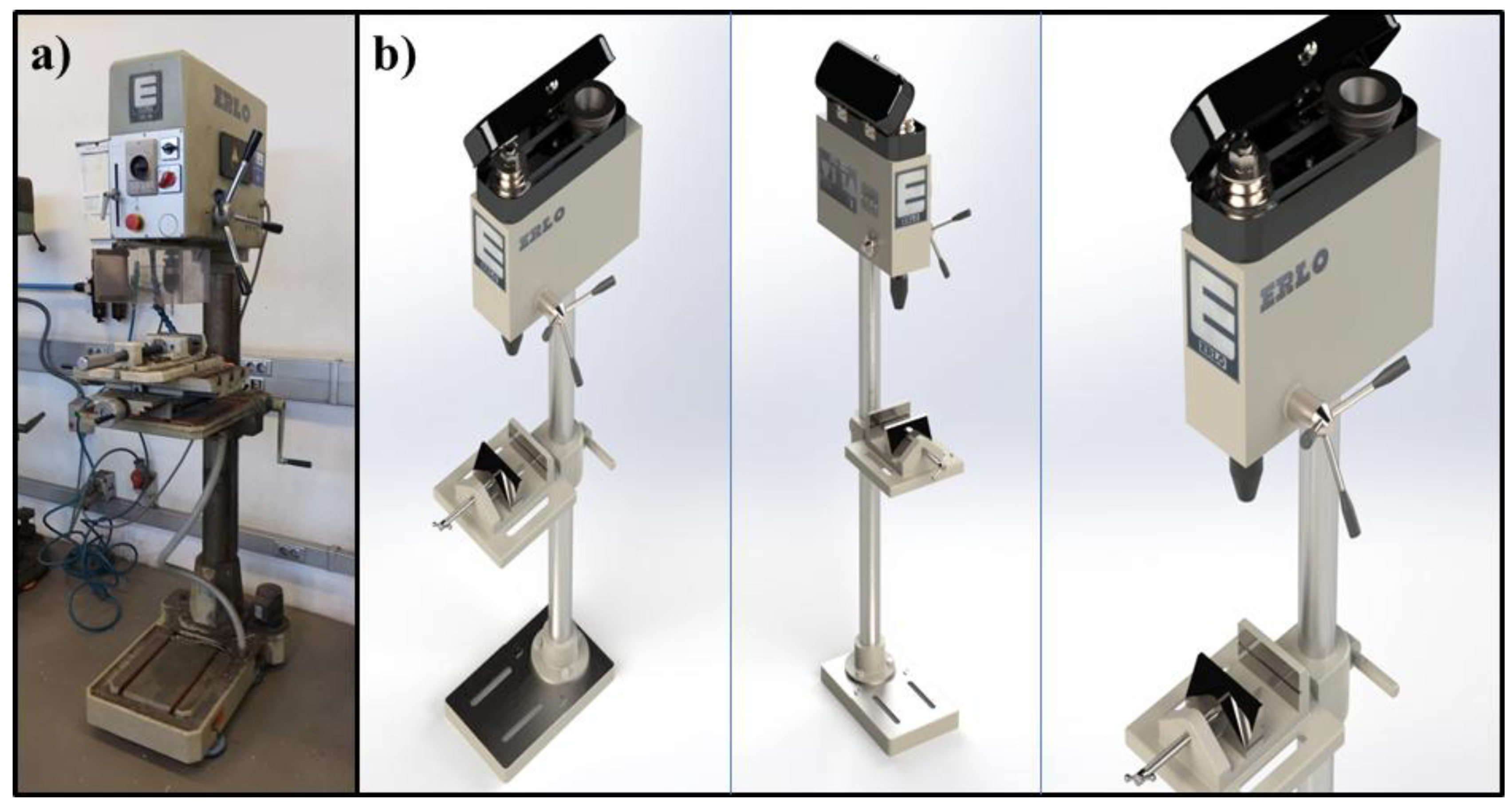
Finally, all components and subassemblies are integrated into a single assembly file, with textures applied to enhance the realism of the model. The final results are presented in several figures: Figure 10a shows the actual image of the ERLO drill press, while Figure 10b shows the assembly result of the virtually created parts from a right and left perspective. The right-hand section of Figure 10b is a close-up view where the assembly details, such as the upper pulleys and the work table, can be better appreciated.
As demonstrated in Figure 10, the similarity between the real machine and the virtual recreation is remarkable. This high level of accuracy makes these 3D resources valuable tools for educational purposes. They allow instructors to effectively teach the functionality of machine tools in a realistic and detailed manner, eliminating the need for access to a physical workshop or an actual drilling press.
4. Conclusions
This study successfully developed a complete digital model of a manually operated vertical drill press, demonstrating the potential of virtual recreation as a tool for industrial heritage preservation and education. By utilizing advanced 3D modeling techniques in SolidWorks, this research has provided a detailed and interactive representation of a historically significant machine, enabling a deeper understanding of its mechanics, components, and operational principles. The digital reconstruction of historical machine tools offers an effective means of preserving their legacy, ensuring that valuable knowledge about past manufacturing processes is not lost to technological obsolescence.
Additionally, the virtual model serves as an accessible and interactive educational resource, allowing students and professionals to explore the structure and function of the drill press without requiring physical access to the machine. This enhances teaching methodologies in technical and engineering education, particularly in resource-limited environments. Moreover, by replacing hands-on training with virtual simulations, the risks associated with operating heavy machinery are significantly reduced, enabling safe experimentation, especially for inexperienced users, while also offering greater flexibility in learning.
Beyond educational benefits, the methods employed in this study can be extended to other industrial machines, facilitating the creation of virtual museums. The integration of augmented or virtual reality could further enhance the immersive experience of interacting with these digital heritage assets. As technology continues to evolve, adopting virtual recreations in historical and educational contexts will become increasingly relevant, bridging the gap between past and present manufacturing knowledge. Future research could explore expanding this approach by incorporating dynamic simulations or haptic feedback systems to create more comprehensive and engaging educational experiences.
Author Contributions
Conceptualization, J.J.J.-G and M.A.M.-M; methodology, J.J.J.-G and S.M.-B.; software, M.A.M.-M; validation, J.J.J.-G and S.M.-B.; formal analysis, J.J.J.-G and M.A.M.-M; investigation, J.J.J.-G and M.A.M.-M; resources, J.J.J.-G and M.A.M.-M; data curation, J.J.J.-G and M.A.M.-M; writing—original draft preparation, J.J.J.-G; writing—review and editing, S.M.-B. and J.J.J.-G; visualization, J.J.J.-G; supervision, J.J.J.-G and S.M.-B.; project administration, J.J.J.-G; funding acquisition, J.J.J.-G. All authors have read and agreed to the published version of the manuscript.
Funding
This research received no external funding.
Data Availability Statement
The datasets used and/or analyzed during the current study are available from the corresponding author on reasonable request.
Acknowledgments
The authors thank the University of Malaga–Andalucia Tech Campus of International Excellence and the Junta de Andalucía Government for its contribution to this paper.
Conflicts of Interest
The authors declared no potential conflicts of interest with respect to the research, authorship, and/or publication of this article.
References
- Vera, M.R. La fábrica de azúcar El Tarajal (Málaga), obra del arquitecto. Vegueta 2022, 22, 263–287. [Google Scholar] [CrossRef]
- De Gregorio, S.; De Vita, M.; De Berardinis, P.; Palmero, L.; Risdonne, A. Designing the Sustainable Adaptive Reuse of Industrial Heritage to Enhance the Local Context. Sustainability 2020, 12, 9059. [Google Scholar] [CrossRef]
- Claver, J.; García-Domínguez, A.; Sevilla, L.; Sebastián, M.A. A Multi-Criteria Cataloging of the Immovable Items of Industrial Heritage of Andalusia. Appl. Sci. 2019, 9, 275. [Google Scholar] [CrossRef]
- Hain, V.; Ganobjak, M. Forgotten industrial heritage in virtual reality—Case study: Old Power Plant in Piešt’any, Slovakia. Presence: Teleoperators Virtual Environ 2017, 26, 355–365. [Google Scholar] [CrossRef]
- Rubio, E.M.; Sanz, A.; Sebastián, M.A. Virtual reality applications for the next-generation manufacturing. Int J Comput Integr Manuf 2005, 18, 601–609. [Google Scholar] [CrossRef]
- Li, J.; Liang, W. Effectiveness of virtual laboratory in engineering education: A meta-analysis. PLoS ONE 2024, 19, e0316269. [Google Scholar] [CrossRef]
- Yang, C.; Zhang, J.; Hu, Y.; Yang, X.; Chen, M.; Shan, M.; Li, L. The impact of virtual reality on practical skills for students in science and engineering education: A meta-analysis. IJ STEM Ed 2024, 11, 28. [Google Scholar] [CrossRef]
- Sebastián, M.A.; Gil, J.C.; Prieto, M.V.; Hurtado, L.S.; Carretero, A.G. Estudio técnico y contextual de las prensas de husillo de las Reales Fábricas de San Juan de Alcaraz de Riópar (Albacete). Técnica industrial 2021, 330, 28–35. [Google Scholar] [CrossRef]
- Granados-Ortiz, F.J.; Gómez-Merino, A.I.; Jiménez-Galea, J.J.; Santos-Ráez, I.M.; Fernández-Lozano, J.J.; de Gabriel, J.M.G.; Casanova, J.O. Estudio cuantitativo multidimensional de la experiencia de evaluación 360 encuestada en prácticas de ingeniería industrial. RELIEVE - Rev Electron Investig Eval Educ 2023, 29, 1–30. [Google Scholar] [CrossRef]
- Menéndez, M.D.C.R.; Calvo, J.V.P.; Caro, M.I. Validación de la teoría cognitivo social de desarrollo de la carrera con una muestra de estudiantes de ingeniería. Educación XX1 2015, 18. [Google Scholar] [CrossRef]
- King, L.; Stark, J.F.; Cooke, P. Experiencing the Digital World: The Cultural Value of Digital Engagement with Heritage. Herit. Soc 2016, 9, 76–101. [Google Scholar] [CrossRef]
- De la Peña Esteban, F.D.; Giralt, C.H.; García, A.J.P. Las nuevas tecnologías y la educación en el ámbito del patrimonio cultural. «Madrid Industrial, Itinerarios». Un ejemplo de m-learning aplicado al patrimonio industrial. Rev Tec Cienc Educ 2015, 51–82. [CrossRef]
- Szromek, A.R.; Herman, K. A Business Creation in Post-Industrial Tourism Objects: Case of the Industrial Monuments Route. Sustainability 2019, 11. [Google Scholar] [CrossRef]
- Martín-Béjar, S.; Claver, J.; Sebastián, M.A.; Sevilla, L. Graphic Applications of Unmanned Aerial Vehicles (UAVs) in the Study of Industrial Heritage Assets. Appl Sci 2020, 10, 8821. [Google Scholar] [CrossRef]
- Wu, H.K.; Lee, S.W.Y.; Chang, H.Y.; Liang, J.C. Current status, opportunities and challenges of augmented reality in education. Comput. Educ 2013, 62, 41–49. [Google Scholar] [CrossRef]
- Lee, K. Augmented reality in education and training. TechTrends 2012, 56, 13–21. [Google Scholar] [CrossRef]
- Corrales Serrano, M.; Garrido Valverde, J. Uso del patrimonio y aprendizaje de la historia de la ciudad. Una experiencia de gamificación en la alcazaba de Badajoz. Dehesa Rep. Inst 2020. [CrossRef]
- Giuliani, F.; De Falco, A.; Landi, S.; Bevilacqua, M.G.; Santini, L.; Pecori, S. Reusing grain silos from the 1930s in Italy A multi-criteria decision analysis for the case of Arezzo. J Cult Herit 2018, 29, 145–159. [Google Scholar] [CrossRef]
- Nocca, F. The Role of Cultural Heritage in Sustainable Development: Multidimensional Indicators as Decision Making Tool. Sustainability 2017, 9, 1882. [Google Scholar] [CrossRef]
- Galea, J.J. Diseño para la sostenibilidad en el coche eléctrico. Del Milburn Model 22 “Brougham” de 1916 al Renault Zoe de 2019. I+Diseño 2019, 14, 277–288. [Google Scholar] [CrossRef]
- Galea, J.J. Evolución del diseño de la Ducati 916 de Tamburini en algunos modelos de motocicletas. I+Diseño 2016, 11, 118–126. [Google Scholar] [CrossRef]
- Cossons, N. Why preserve the industrial heritage? TICCIH Routledge 2016, 6–16. [Google Scholar]
- Linde-Valenzuela, T.L.; Guillén-Gámez, F.D.; Cívico-Ariza, A.; Sánchez-Vega, E. Tecnología y educación en tiempos de cambio. RIUMA 2021. [Google Scholar]
- Rodríguez-García, B.; Guillen-Sanz, H.; Checa, D.; Bustillo, A. A systematic review of virtual 3D reconstructions of Cultural Heritage in immersive Virtual Reality. Multimed Tools Appl 2024, 1–51. [Google Scholar] [CrossRef]
- Leal Filho, W.; Salvia, A.L.; Do Paço, A.; Anholon, R.; Quelhas, O.L.G.; Rampasso, I.S. A comparative study of approaches towards energy efficiency and renewable energy use at higher education institutions. J Clean Prod 2019, 237, 117728. [Google Scholar] [CrossRef]
- Zhou, Q.; Wang, S.; Wang, J. Exploring User Experience in Virtual Industrial Heritage Platforms: Impact of Cultural Identity, Functional Clarity, Scene Interactivity, and Narrative Quality. Buildings 2025, 15, 253. [Google Scholar] [CrossRef]
- Choi, S.; Jung, K.; Noh, S.D. Virtual reality applications in manufacturing industries: Past research, present findings, and future directions. Concurrent Eng 2015, 23, 40–63. [Google Scholar] [CrossRef]
- Kavanagh, S.; Luxton-Reilly, A.; Wuensche, B.; Plimmer, B. A systematic review of virtual reality in education. TISTED 2017, 10, 85–119. [Google Scholar]
- Gómez-Merino, A.I.; Jiménez-Galea, J.J.; Rubio-Hernández, F.J.; Santos-Ráez, I.M. Experimental assessment of thermal and rheological properties of coconut oil-silica as green additives in drilling performance based on minimum quantity of cutting fluids. J Clean Prod 2022, 368, 133104. [Google Scholar] [CrossRef]
Figure 1.
The Erlo CR-18 hand drill.
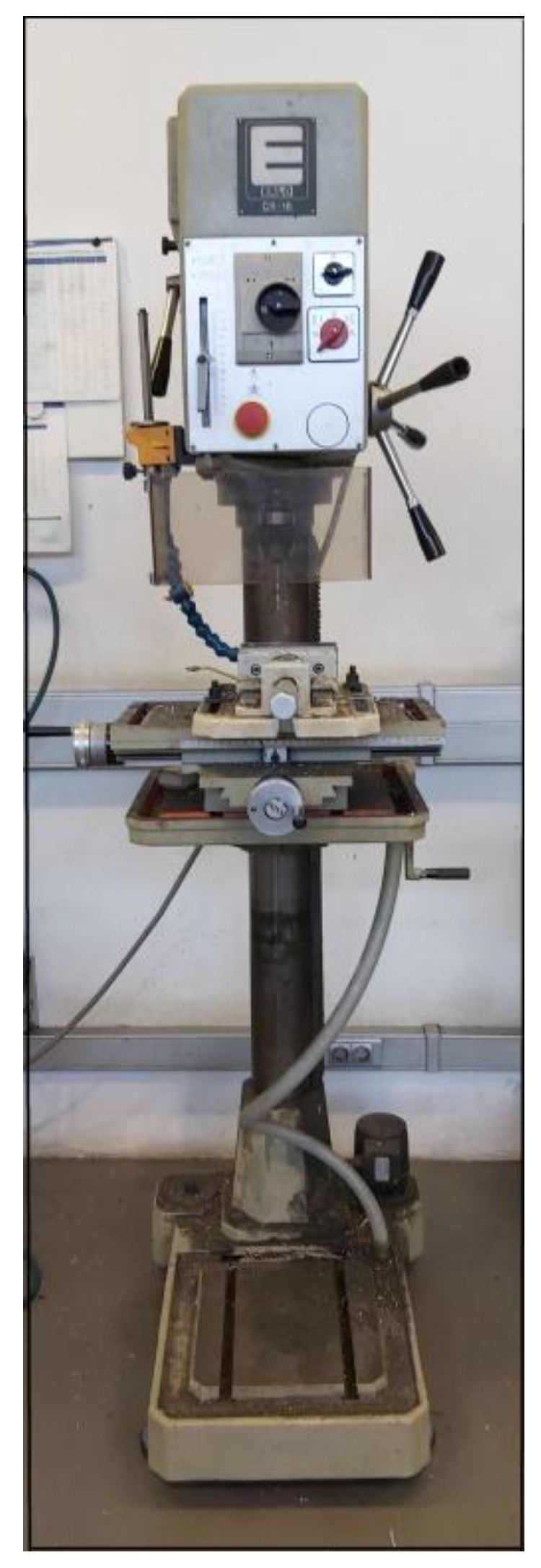
Figure 2.
Virtual recreation of worktable and clamp.
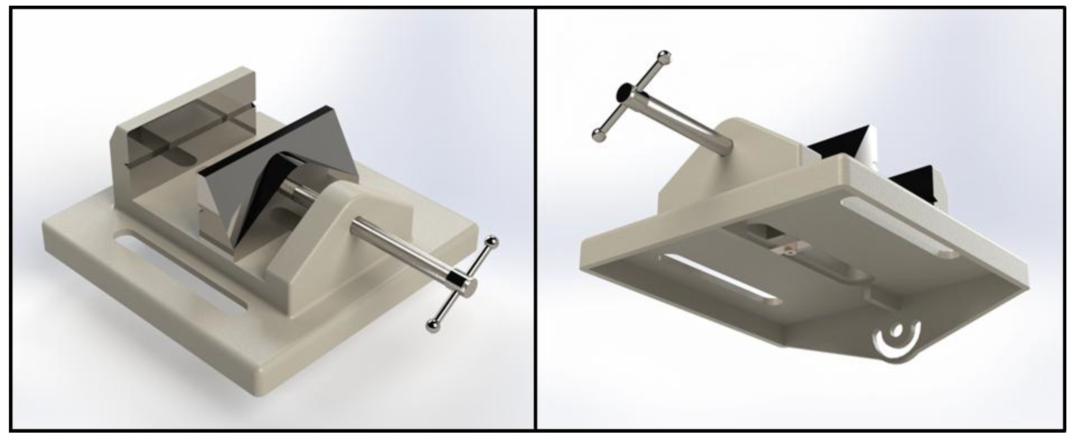
Figure 3.
Virtual recreation of the flywheel axis.
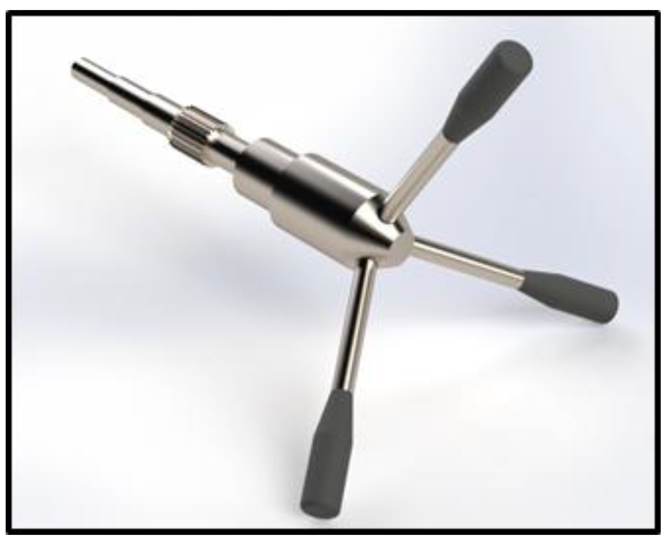
Figure 4.
Virtual recreation of: (a) Drill chuck shaft pulley. (b) Engine pulley. (c) Pulley and belt assembly.
Figure 4.
Virtual recreation of: (a) Drill chuck shaft pulley. (b) Engine pulley. (c) Pulley and belt assembly.
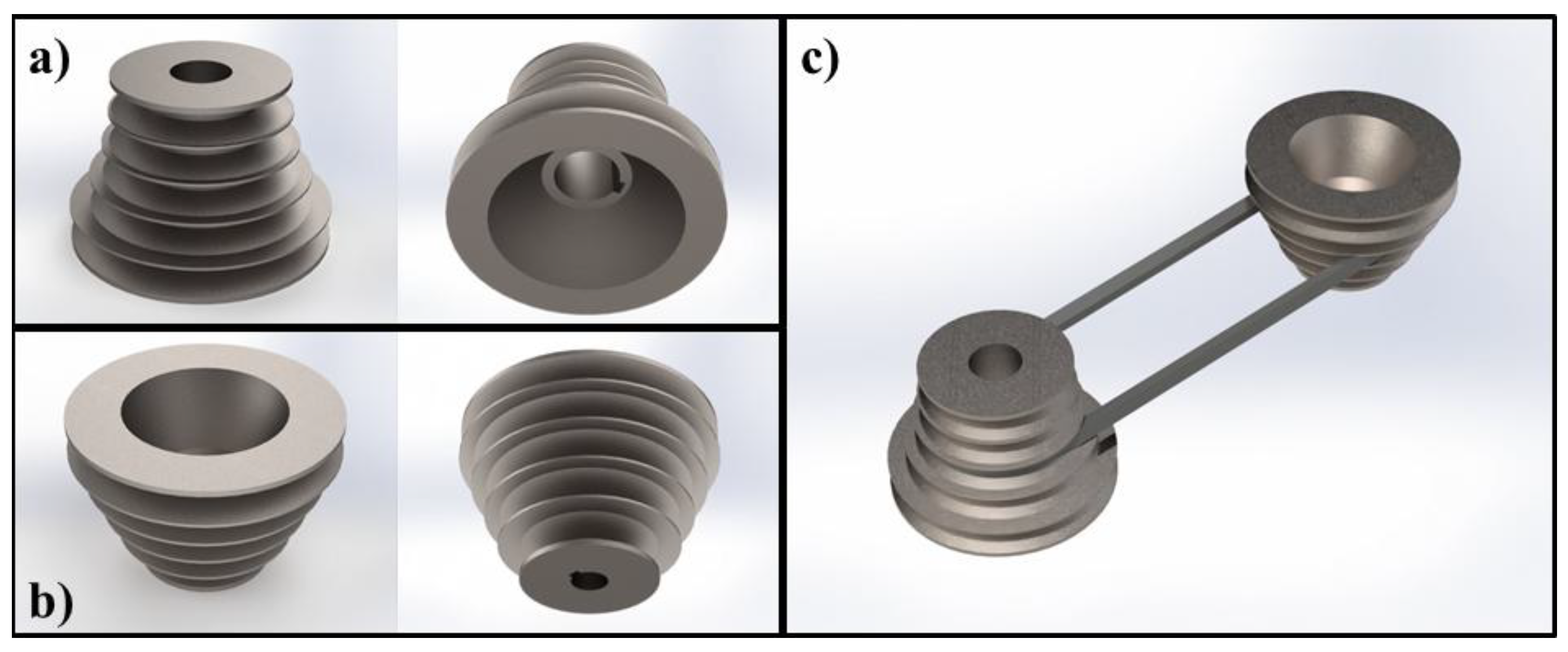
Figure 5.
Virtual recreation of: (a) Base. (b) Column. (c) Clamping ring.
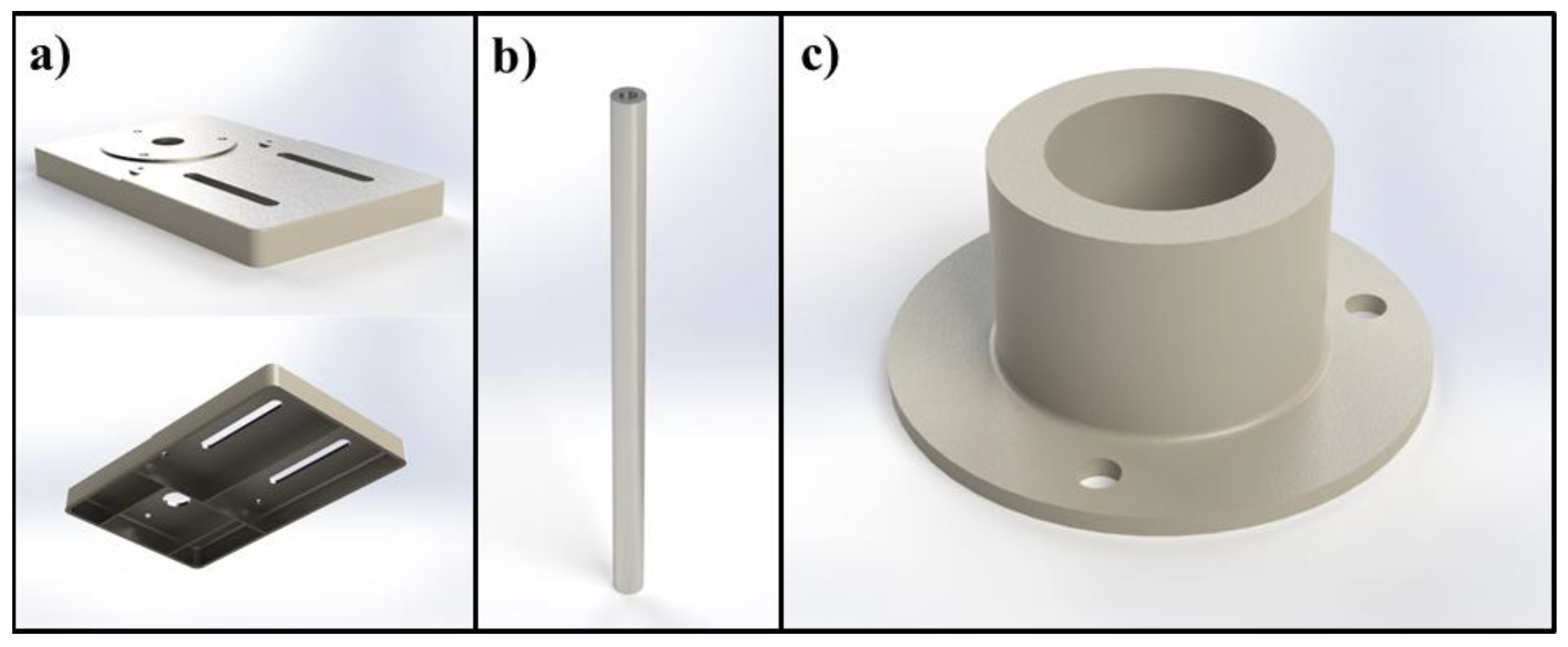
Figure 6.
Virtual recreation of: (a) Clamp. (b) bracelet lock.
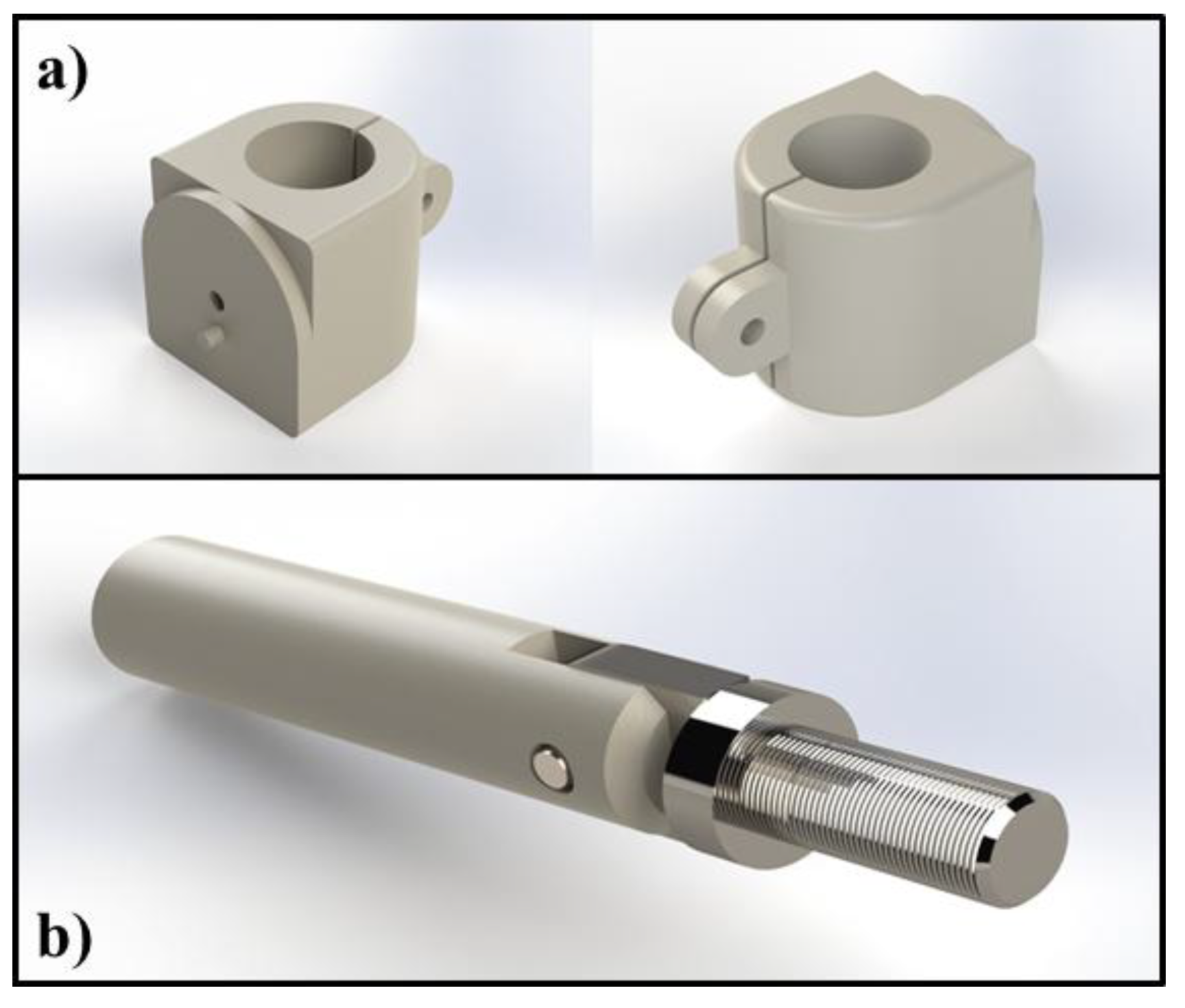
Figure 7.
Virtual recreation of: (a) Body. (b) Sleeve.
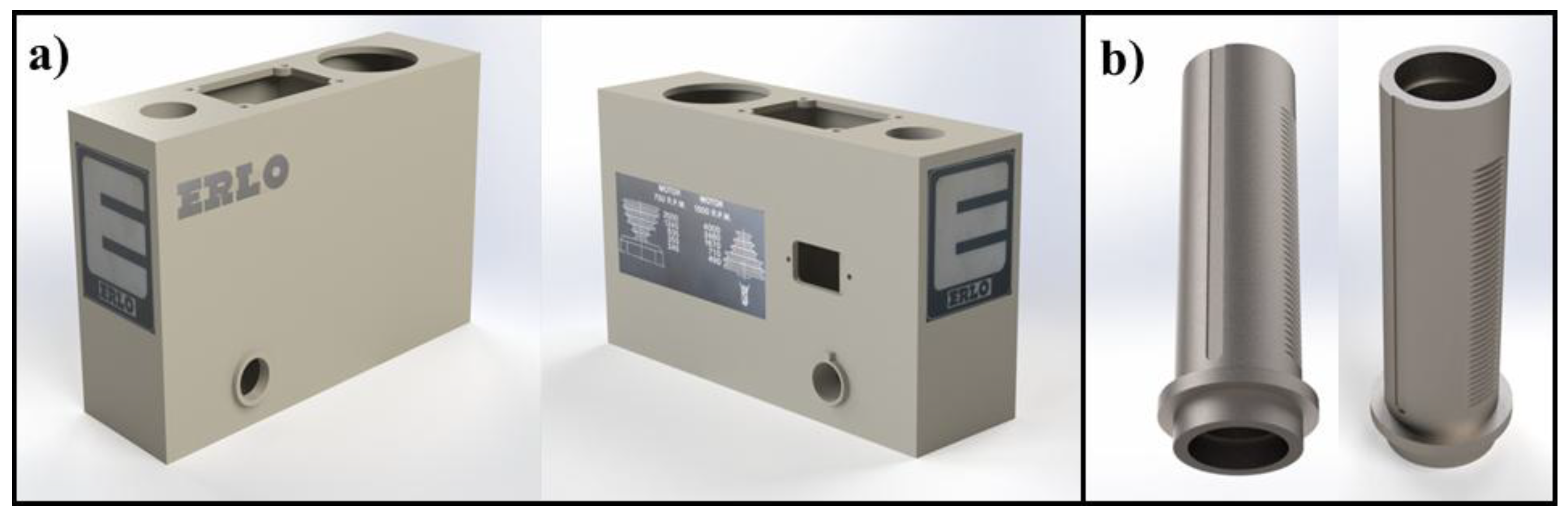
Figure 8.
Virtual recreation of: (a) Spindle. (b) The pulley insert. (c) Drill chuck.
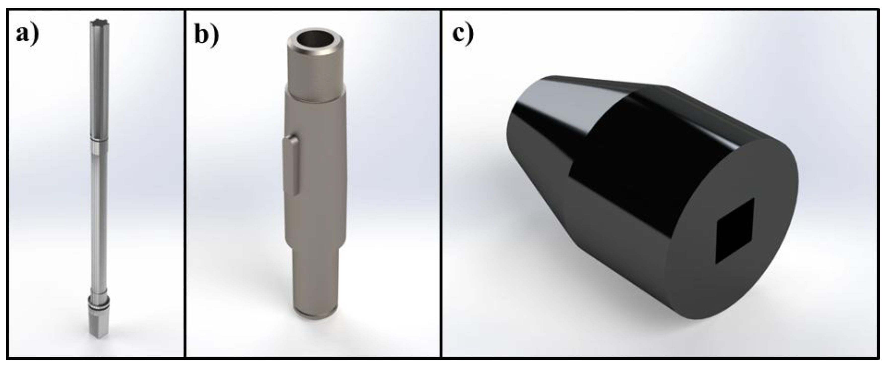
Figure 9.
Virtual recreation of the pulley cover.
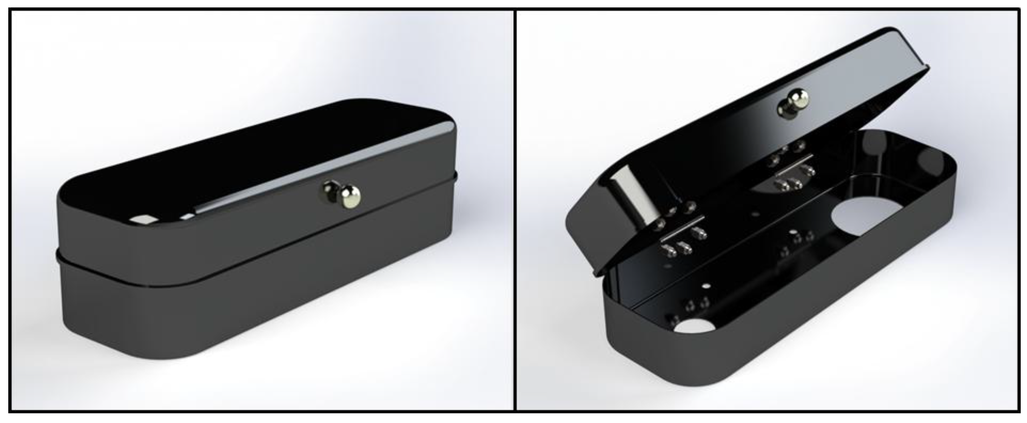
Figure 10.
(a) Real ERLO machine. (b) Virtual recreation of a vertical drilling press from different perspectives. Key components such as the worktable, clamp, drill chuck, and column can be seen highlighted.
Figure 10.
(a) Real ERLO machine. (b) Virtual recreation of a vertical drilling press from different perspectives. Key components such as the worktable, clamp, drill chuck, and column can be seen highlighted.
Disclaimer/Publisher’s Note: The statements, opinions and data contained in all publications are solely those of the individual author(s) and contributor(s) and not of MDPI and/or the editor(s). MDPI and/or the editor(s) disclaim responsibility for any injury to people or property resulting from any ideas, methods, instructions or products referred to in the content. |
© 2025 by the authors. Licensee MDPI, Basel, Switzerland. This article is an open access article distributed under the terms and conditions of the Creative Commons Attribution (CC BY) license (http://creativecommons.org/licenses/by/4.0/).
Copyright: This open access article is published under a Creative Commons CC BY 4.0 license, which permit the free download, distribution, and reuse, provided that the author and preprint are cited in any reuse.


