Submitted:
28 November 2025
Posted:
01 December 2025
You are already at the latest version
Abstract
In view of the requirements and characteristics that a deep-sea polymetallic nodule collector must travel according to a planned path and speed during operation, a collector trajectory tracking system scheme based on virtual target vehicle following is proposed. In this system, the virtual target vehicle travels according to the planned path and speed, thereby generating a dynamic target path and speed. A fuzzy controller calculates the collector’s angular-velocity command based on the lateral position deviation and the heading-angle deviation between the collector and the target vehicle, and a proportional controller calculates the collector’s body linear velocity control command based on the longitudinal position deviation between the collector and the target vehicle. By integrating these two commands, the collector follows the target vehicle and thereby realizes trajectory tracking of the planned path and speed. A tracking system is designed and simulation studies are carried out. The results show that the designed system enables the collector to follow the planned path and speed well under operational conditions. The trajectory tracking method based on virtual target vehicle following can also form an organic integration of path planning and trajectory tracking, generate dynamic planned paths and speeds for the entire mining area, and realize tracking travel of the collector along the planned path and speed throughout the whole operation.
Keywords:
trajectory tracking
; deep-sea collector
; target vehicle following
; planned path
1. Introduction
Because deep-sea polymetallic nodules are rich in critical minerals such as nickel, cobalt, copper, and manganese, their exploitation has attracted significant international attention. Polymetallic nodules are potato-shaped and partially embedded in deep-sea sediments. During mining, a tracked collector travelling over the seafloor sediments collects the nodules through mechanical or hydraulic methods and transports them to a conveying pipeline, which then pumps them to the mining vessel at the surface[1,2]. For this reason, deep-sea polymetallic nodule collectors are also often referred to as deep-sea mining robots [3]. To ensure thorough collection of nodules within the seabed mining area, the collector usually performs full-area traversal during operation, advancing in straight-line loops across the mining field, in a pattern analogous to that of a lawn-mowing operation [4,5]. Due to the length limitation of the flexible hose, the collector must turn back after traveling in a straight line for approximately 600 m on the seabed. At the same time, because both the bearing capacity and shear strength of seabed sediments are relatively low [6,7], the collector generally performs turning maneuvers along circular-arc paths with a relatively large turning radius during each reversal[8,9], to prevent slipping and sinkage [10]. Before mining deep-sea polymetallic nodules, it is necessary to plan and design the collector’s travelling path and speed according to the above requirements. Depending on the relative arrangement of the turning arcs and the straight outbound–return lines, the planned paths are mainly classified into two types: the “keyhole type” [11] and the “bulb type” [12]. During polymetallic nodule mining operations, the collector is required to travel along the planned path; therefore, the collector’s travelling during operation is also a process of tracking and executing the planned path and speed.
As a key technology in deep-sea polymetallic nodule mining, considerable research has been conducted on path tracking for the operational travelling of collectors.
In terms of path tracking methods and strategies, Yoon et al. adopted a pure pursuit–based approach, in which preview points on the target path are continuously selected and updated, and the collector’s travelling speed and angular velocity are adjusted to approach the preview points, yielding good simulation and experimental results [13]. Yeu et al. proposed a path-tracking algorithm for the collector to follow a predefined path using a vector tracking method [14]. Mao et al., based on the principle of the Stanley method, proposed an algorithm that regulates the speed difference between the collector’s two tracks according to the heading deviation to perform target path tracking, and verified the feasibility of the method through simulations [15].
More studies have focused on control algorithms for reducing the deviation between the collector and the desired path. Commonly used methods include fuzzy control, model predictive control (MPC), and sliding mode control (SMC), as well as combined applications of different control approaches. Regulating the vehicle’s angular velocity according to the heading angle deviation and path deviation between the vehicle body and the target path is a common method for path tracking of tracked vehicles, and the dual-input, single-output structure of conventional fuzzy controllers fits this characteristic well. Therefore, fuzzy control algorithms have been widely applied in studies on collector path tracking [16,17,18]. To improve control accuracy, Li et al. adopted a variable-universe method in the design of the fuzzy controller [17], while Dai et al. applied a fuzzy adaptive PID control method to directly compute the collector’s track velocities and velocity ratio [18]. However, in the fuzzy PID controller designed by Mao for path tracking, the input variables were the heading angle deviation between the collector and the target path and its rate of change [15]. Cao [19] and Wu [20] conducted MPC-based studies on path tracking for deep-sea collectors. After linearizing and discretizing the kinematic model of the tracked collector, they constructed a predictive model by selecting the prediction horizon according to the MPC approach, formulated a quadratic performance evaluation function, performed rolling optimization, and carried out error correction. Simulation analyses verified the effectiveness of the proposed algorithms. g Chen et al. combined SMC and MPC for the collector’s path tracking [21]. First, a sliding-mode control law was designed to enable rapid convergence of trajectory tracking errors, and then MPC was used to perform predictive optimization of the control law. Simulation results show that this combined control method can not only improve path tracking accuracy but also suppress the chattering caused by using sliding-mode control alone.
Some studies have paid attention to issues such as track slippage during the collector’s travelling on seabed sediments, but most of them remain at the level of making corrections based on assumptions or estimations—for example, applying slip-ratio compensation to the computed track velocities [16,17], or limiting the collector’s maximum angular velocity [15,20]. Chen et al. proposed a path-tracking method that compensates for the collector’s longitudinal deviation. Based on the Stanley tracking principle, they used a PD control algorithm to correct the lateral deviation between the collector and the target path, while employing an unscented Kalman filter to estimate and compensate for longitudinal offsets caused by slippage and other factors. Simulation analysis demonstrated that this method can reduce longitudinal deviation and heading-angle deviation during path tracking [22]. Qihang Chen et al. established a collector dynamic model that accounts for nonlinear slip and random resistance, and designed a path-tracking controller based on the deep deterministic policy gradient algorithm. Through simulation and experimental studies, they showed that stable and rapid path-tracking performance can be achieved under conditions closer to actual mining operations [23].
Overall, considerable research has been conducted on path tracking for deep-sea collectors. Most of these studies are rooted in the foundations and developments of path-tracking research for land vehicles, verifying the feasibility of applying such methods to deep-sea collector path tracking, while also revealing issues that require further investigation. For example, regarding path-tracking methods, the pure pursuit method uses a circular-arc route to move toward preview points, which may provide smooth turning advantages when tracking straight-line paths [11]; however, during collector operations, large-curvature turning along circular arcs is frequently required, making the selection of preview points inconvenient. The Stanley tracking method, on the other hand, was originally proposed for wheeled vehicles and is not suitable for direct application to tracked collectors. In terms of control algorithms for reducing path deviation, sliding-mode control may exhibit robustness to certain uncertain variations in the system (such as disturbances caused by track slippage), but the high-frequency switching required near the sliding surface may aggravate track slippage on the seabed and increase disturbance to the sediment [24]. The model predictive control method improves path-tracking performance by predicting future states, but it relies heavily on the accuracy of the system model. The nonlinear characteristics of the collector’s travelling dynamics make the model and algorithm complex, which affects their practical engineering application. On the other hand, although phenomena such as track slippage during seabed travelling of collectors objectively exist [25], current research on the interaction between tracks and seabed sediments remains immature. Slip coefficients adopted based on assumptions cannot represent the varying slippage conditions, and some established dynamic models cannot accurately reflect the mechanisms and patterns of slippage. Moreover, the algorithms are complex and computationally intensive, making them difficult to apply to the real-time control of deep-sea collectors.
From the existing literature, most of these studies focus solely on eliminating the deviation between the vehicle body and the target path, which falls under path tracking in vehicle motion-control research. However, during deep-sea polymetallic nodule mining operations, the collector must maintain a certain speed during straight-line travelling to ensure nodule production capacity [26], while the travelling speed must be reduced during turning maneuvers to avoid slippage [27]. Therefore, the operational travelling of deep-sea collectors must follow not only the planned path but also the planned speed, which constitutes trajectory tracking of the planned path. From the perspective of planned path characteristics, polymetallic nodules are generally located on deep-sea plains below 4 km. Although features such as trenches or seamounts may also be present, the slope of actual mining areas is generally less than 5%, and the collector’s travelling during operation is a planar motion. Regarding path characteristics, each outbound-and-return trip includes straight lines required by the traversal operation as well as turning arcs with large curvature. At the scale of the entire mining area, the collector travels repeatedly along the same planned path. In terms of travelling control, GPS information is not available in the deep sea, and collectors rely on acoustic and inertial navigation technologies for positioning and navigation. The controllers and actuators must also meet the requirements of the deep-sea environment. As a result, the application of some advanced trajectory-tracking methods and technologies used in land vehicles is constrained when applied to deep-sea collectors.
Based on the characteristics of the planned travelling path for collector mining operations and the operational conditions of the deep-sea environment, this paper proposes a trajectory-tracking method for the collector to follow the planned path and speed, using virtual target vehicle following. Fuzzy control and proportional control algorithms, which are convenient for engineering implementation, are employed to regulate the collector’s angular velocity and linear velocity, enabling the collector to travel according to the planned path and speed throughout the entire operation.
2. Trajectory-Tracking Scheme for Implementing the Planned Path Based on Virtual Target Vehicle Following
2.1. Trajectory-Tracking Method for the Planned Path Based on Virtual Target Vehicle Following
The pure pursuit method, the Stanley method, and the vector tracking method all belong to geometric approaches. They perform path tracking by gradually selecting preview points along the target path and moving toward those points. Their basic idea can be summarized as the so-called “carrot-chasing method”: moving a carrot slowly in front of an animal to induce it to move toward the carrot’s position. As a geometric approach, these tracking methods do not consider the moving speed of the carrot, and as a point, it has neither a heading angle nor an angular velocity. Clearly, for trajectory tracking of a large collector operating along complex paths that require frequent turning, such information is insufficient. To address this issue, a trajectory-tracking scheme for implementing the planned path based on virtual target vehicle following is proposed. In this scheme, on one hand, a virtual target vehicle with the same structure and performance characteristics as the collector is constructed. This virtual target vehicle travels according to the planned path and speed preset by the mining process, thereby forming the dynamic planned travelling path and speed of the collector’s operation. On the other hand, the collector minimizes its position and heading-angle deviations from the target vehicle by adjusting its own travelling speed and angular velocity according to the real-time deviations in position and heading angle between the two, thus achieving trajectory tracking of the planned path. Figure 1 illustrates the trajectory-tracking method for the planned path based on virtual target vehicle following. In the figure, Pm(xm,ym,θm) and Ps(xs,ys,θs) represent the positions and heading angles of the target vehicle and the collector, respectively. Compared with geometric tracking methods, the trajectory of the target vehicle is not merely a sequence of preview points on the target path, but a planned path formed by continuously travelling along the preset path and speed. Furthermore, the collector’s tracking toward the target vehicle relies not only on the position deviation between the collector and the target path, but also on the heading-angle deviation between the collector and the target vehicle.
2.2. Kinematic Model of the Collector and the Virtual Target Vehicle
Since the virtual target vehicle is assumed to have the same structure and performance as the collector, they share the same kinematic model. The collector’s travelling on the seabed can be regarded as planar motion, and its kinematic model can be expressed as:
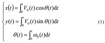
In the above equation, V0 denotes the linear velocity at the collector’s center of mass, ω0 denotes its angular velocity, and t represents time.
Both the collector and the target vehicle are tracked vehicles, whose straight-line travelling or turning is controlled by the speed difference between the left and right tracks. As shown in Figure 2, and without considering slippage, the relationship among the center velocity V0, angular velocity ω0, and the left and right track speeds VL and VR is given by:
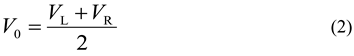
In the above equations, D is the distance between the centers of the two tracks. From (2) and (3), it can be seen that once the center velocity and angular velocity of the collector are determined, the travelling speeds of the left and right tracks are also determined. Therefore, in the motion control of the collector, its center velocity and angular velocity can be taken as the control variables.
2.3. Pose Deviation Between the Collector and the Virtual Target Vehicle
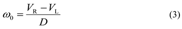
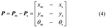
In Figure 1, Ps(xs,ys,θs) and Pm(xm,ym,θm) represent the positions and heading angles of the collector and the target vehicle in the geodetic coordinate system, respectively. Their position and heading-angle deviations can be expressed as:
However, during trajectory tracking, since the onboard acoustic beacons, inertial navigation systems, side-scan sonars, controllers, hydraulic motors, and other actuators are all mounted on the collector, it is more convenient to make trajectory-tracking decisions and implement control from the collector’s perspective—namely, based on the position and heading-angle deviations between the collector and the target vehicle expressed in the collector’s body coordinate system. Therefore, the pose deviation between the collector and the target vehicle in the geodetic coordinate system must be transformed into the pose deviation between the two in the collector’s coordinate system. According to the transformation method of planar Cartesian coordinate systems, the position and heading-angle deviations between the collector and the target vehicle in the collector’s coordinate system can be expressed as:
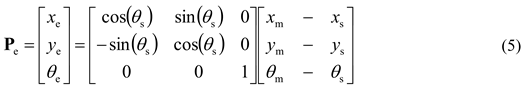
where xe, ye and θe denote the position and heading-angle deviations between the collector and the target vehicle in the collector’s coordinate system.
2.4. Control Algorithms for Reducing Pose Deviation
In the tracking method proposed in this paper, the virtual target vehicle travels according to the planned path and speed. If tracking control enables the pose deviation between the collector and the virtual target vehicle to reach zero, trajectory tracking of the planned path is thereby achieved. According to Equation (5), the pose deviation consists of the longitudinal position deviation xe, the lateral position deviation ye, and the heading-angle deviation θe. Although, in principle, these three deviations could be used as input variables to design a trajectory-tracking controller, such a controller would inevitably become complex. From Figure 1, the lateral deviation ye represents the distance between the collector and the planned path, while the heading-angle deviation θe is the key factor for path correction. The planned path can be tracked based on these two deviations. The longitudinal deviation xe represents the distance between the collector and the target vehicle along the direction of the planned path. If xe remains zero, it indicates that the collector and the target vehicle are travelling at the same speed; therefore, xe can be used to control the collector’s tracking of the planned speed. This approach—separately tracking the planned path and the planned speed—can substantially reduce the complexity of the controller.
Regarding control algorithms, although various approaches have been explored, limitations still exist when considering engineering applications in deep-sea mining operations. In comparison, the dual-input single-output structure of the conventional fuzzy controller is highly suitable for designing a controller that adjusts the collector’s angular velocity based on the lateral position deviation and heading-angle deviation. Moreover, this method directly computes control commands from the path and heading-angle deviations without relying on the dynamic model of the collector’s travelling, providing good operability and robustness. On the other hand, adjusting the collector’s travelling speed according to longitudinal position deviation is physically intuitive. From a control perspective, constructing a proportional controller that uses longitudinal position deviation as the input variable is not only simple but also efficient and practical.
2.5. Trajectory-Tracking System for the Planned Path Based on Virtual Target Vehicle Following
According to the proposed tracking method and the analysis of the control algorithms, a trajectory-tracking control system for the collector’s operational planned path based on virtual target vehicle following can be constructed, as shown in Figure 3.
In this system, the predesigned planned path is stored in the “Planned Path” module in data form, and dynamic position and heading-angle information is generated through the “Target Vehicle Travelling Computation” module. The “Coordinate Transformation and Deviation Computation” module calculates the pose deviation between the collector and the target vehicle in the collector’s body coordinate system based on their positions and heading angles in the geodetic coordinate system. The path-tracking and speed-tracking controllers compute the collector’s angular-velocity and linear-velocity commands, respectively, from this pose deviation, enabling the collector to perform trajectory tracking of the planned path and speed. To prevent sudden changes in speed from causing impact disturbances to the seabed sediment, incremental control commands are adopted for both the angular-velocity fuzzy controller and the speed proportional controller. Meanwhile, nonlinear saturation limits are applied to the speed and angular velocity based on the maximum track speed of the collector.
3. Controller Design and Control-Performance Analysis of the Trajectory-Tracking System.
3.1. Design of the Angular-Velocity Fuzzy Controller for Path Tracking.
According to Figure 3 and the related analysis, an angular-velocity fuzzy controller is designed by taking the lateral position deviation ye and the heading-angle deviation θe as input variables, and the incremental angular velocity △ωs of the collector as the output variable. Seven fuzzy subsets are defined for each input and output variable, namely NB (Negative Big), NM (Negative Medium), NS (Negative Small), ZE (Zero), PS (Positive Small), PM (Positive Medium), and PB (Positive Big). Regarding the selection of membership-function types, Gaussian membership functions are chosen for both the input and output variables to accelerate correction when deviations are large and to prevent overshoot when deviations are small. The universes of discourse are set as [-3,3] for the lateral deviation ye, and [-1,1] for the heading-angle deviation θe and the angular-velocity increment △ωs.
On this basis, fuzzy control rules are designed in the form of “if–then” logical reasoning according to the magnitude and sign of the lateral deviation and heading-angle deviation. The basic principles are as follows: If ye and θe have the same sign, the collector’s heading angle deviates from the target path in the collector coordinate system; in this case, the collector should apply a positive (or negative) angular-velocity increment depending on whether ye and θe are positive (or negative), with larger increments assigned for larger deviations. If ye and θe have opposite signs, the collector’s direction of motion is already pointing toward the target path. When the position deviation is small but the heading-angle deviation is large, a small or moderate angular-velocity increment is chosen. When the position deviation is large but the heading-angle deviation is small, a small increment is applied or the angular velocity is kept unchanged to continue converging toward the target path. Following these principles, the control rules can be designed as shown in Table 1.
By performing fuzzy logical inference according to the above rules and applying the defuzzification method, an exact value of △ωs can be obtained. However, in practice, this exact value can only serve as a trend indication for the collector’s angular-velocity control. As shown in Figure 3, under the virtual target vehicle–based tracking method, the collector adjusts its angular velocity moderately based on the current lateral position deviation and heading-angle deviation relative to the target vehicle, while tracking the target vehicle’s position and motion. The control command is given by ωs=ωm+Kω△ωs. Here, the coefficient Kω regulates the degree of influence of △ωs. Its specific value is determined using the Trial and Error Method, through repeated simulation calculations and comparisons, taking into account both the response speed and overshoot of path correction. In this design, the value is set as Kω=4.
In addition, the collector is a heavy-duty operational device, and its maximum travelling speed generally does not exceed 1 m/s, while the normal operational travelling speed is 0.5–0.6 m/s, and the center velocity during turning is approximately 0.3 m/s [27]. If the distance between the two tracks of the vehicle body is D=12 m [26], then, under a relatively extreme condition in which the inner-track speed is zero, Equations (2) and (3) indicate that the maximum angular velocity of the collector during turning should not exceed 0.05 rad/s. Therefore, in the tracking system shown in Figure 3, the upper and lower limits of the nonlinear saturation block for the collector’s angular velocity ωs are set to ±0.045 rad/s.
3.2. Design of the Linear-Velocity Proportional Controller for Speed Tracking
As mentioned earlier, during actual operations, the collector must follow not only the planned path but also the planned speed. In the previous analysis and system design, a scheme was proposed to track the planned speed by appropriately adjusting the collector’s velocity based on the longitudinal deviation, on the basis of the target vehicle’s center velocity. The specific control law is Vs=Vm+KV△Vs (as shown in Figure 3). The proportional coefficient KV is also determined using the Trial and Error Method through simulation comparisons, and its value is set to 2. Meanwhile, according to the maximum travelling speed of the collector described above, the upper and lower limits of the nonlinear saturation block for the collector’s center velocity Vs are set within the range [0,1].
It should be noted that although the control commands for the collector’s angular velocity and centroidal travelling speed are provided by different controllers, these angular and linear velocities are substituted simultaneously into the collector’s travelling kinematic model for computation, as shown in Figure 3. Therefore, to some extent, the collector’s travelling motion is also coordinately controlled within the same kinematic model.
3.3. Simulation Verification of the Trajectory-Tracking Performance of the Designed System
Using the Fuzzy Logic Toolbox of MATLAB (R2021b), the angular-velocity fuzzy controller was designed, and the trajectory-tracking simulation system of the collector based on target-vehicle following was constructed on the SIMULINK (R2021b) platform according to the structural diagram shown in Figure 3. Based on the operational travelling characteristics of the collector, simulation calculations were carried out for straight-line path tracking and circular-arc path tracking as examples, to verify the performance of the proposed trajectory-tracking system and the feasibility of the simulation system.
- (1)
- Simulation Analysis of Straight-Line Path Tracking
In the geodetic coordinate system, the starting point of the target path is set as (12,20), extending along the X-axis direction (with a heading angle of 0°), and the target speed is set to 0.6 m/s. The initial position of the collector is (8,21), with an initial heading angle of 10°. The collector performs trajectory tracking of the target path and speed. The above target path and the collector’s related data are substituted into the Planned Path module, the Target Vehicle Travelling Computation module, and the Collector Travelling Computation module of the trajectory-tracking simulation system, respectively, as the target and initial conditions. Following the system structure shown in Figure 3, simulation analysis of the travelling processes of the target vehicle and the collector is conducted to generate the dynamic target path and obtain the collector’s travelling path, speed, and angular-velocity variations. The corresponding calculations and comparison results are presented in Figure 4.
From Figure 4(a), it can be seen that although the initial positions of the collector and the target vehicle are separated by several meters, and the collector’s initial heading angle is oriented away from the target path, the collector is able to track the predetermined target path relatively quickly and smoothly under the control of the designed trajectory-tracking system. At approximately 30 s after the start of travelling—when the target vehicle has moved about 18 m—the travelling trajectories of the collector and the target vehicle have become essentially identical. Figure 4(b) shows the variation curves of angular velocity. At the beginning of travelling, the collector is 1 m to the left of the target vehicle’s travelling direction and its heading angle is oriented away from the target path; therefore, the controller commands the collector to approach the target path with the maximum possible angular velocity in the clockwise direction (−0.045 rad/s under the nonlinear saturation limit). Around the 8-second mark, the lateral position error between the collector and the target vehicle has decreased to about 0.7 m. To allow the collector to approach the target path smoothly, the controller commands the collector to begin approaching the target path in a counterclockwise circular-arc manner. As a result, the angular velocity gradually changes from −0.045 rad/s to approximately 0.035 rad/s, and then slowly decreases to the target angular velocity, i.e., 0 rad/s. The evolution of the lateral deviation in Figure 4(c)—featuring an initial rapid convergence followed by a slower final approach—also reflects the successful implementation of the angular-velocity controller’s control strategy. In terms of speed tracking, as shown in Figure 4(d), because the initial position deviation is relatively large (4 m), the collector first tracks the target vehicle at its maximum speed (1 m/s). After approximately 10 s, the centroidal travelling speed decreases rapidly—with a slight overshoot—to 0.6 m/s, and then remains stable at the target speed.
- (2)
- Simulation Analysis of Circular-Arc Path Tracking.
The target path is a circular arc with a radius of 12 m, with a target speed of 0.3 m/s and a target angular velocity of 0.025 rad/s. The collector starts travelling from a point located on the inner side of the circle, with a lateral path deviation of 2 m and an initial speed of 0.3 m/s. Using the established trajectory-tracking simulation platform, simulation calculations were carried out for the collector’s trajectory tracking of the circular path. The time-history curves of the travelling paths, centroidal travelling speed, and path deviation of the target vehicle and the collector are obtained as shown in Figure 5.
From the analysis of Figure 5, it can be seen that the collector accelerates from the initial point to track the target vehicle. Upon reaching the target circular path, a slight overshoot occurs and is then corrected back to the target path. After approximately 40 seconds, the collector’s centroidal travelling speed becomes essentially synchronized with that of the target vehicle. The path deviation between the collector and the target vehicle remains essentially zero after about 90 seconds, indicating that the designed trajectory-tracking system exhibits good tracking performance for circular paths.
3.4. Laboratory Simulation Test of the Trajectory-Tracking System Functions
To verify the functionality of the designed trajectory-tracking system, a laboratory simulation test was conducted. The simulation test system mainly consists of a tracked model vehicle, a positioning system, and a control computer. The positioning system includes base stations and a mobile positioning tag. The positioning base stations are placed at the four corners of the test site, and the mobile positioning tag is mounted on the model vehicle. Through the transmission and reception of ultra-wideband pulse signals between the tag and the base stations, interactive communication is achieved, allowing the tag—and therefore the model vehicle—to be positioned. The control computer is equipped with the backend software of the positioning system and the trajectory-tracking control system software. Based on the positional information provided by the positioning system and the attitude information transmitted from the attitude sensor mounted on the model vehicle, the rotational-speed commands of the two track-driving motors are calculated and wirelessly transmitted to the vehicle’s control module for motion control of the model vehicle. Figure 6 shows photographs of the model vehicle and the positioning base stations arranged at the test site, while Figure 7 presents the simulation-test results of trajectory tracking for a circular target path.
From Figure 7, it can be seen that the model vehicle tracks a circular target path with a diameter of 4 m, starting from an initial position with a radial distance of approximately 0.3 m. After travelling about 2 m, it reaches the circular path, but continues moving forward beyond the preset arc before beginning to correct its deviation and return to the path. Thereafter, it essentially travels along the circular path. A noticeable short-term deviation appears on the trajectory curve of the model vehicle; analysis indicates that this deviation was caused by abnormal drifting of the onboard tag’s positional data during the experiment. Based on the simulation experiment results, although the experimental system and equipment are relatively simple, they still provide a certain degree of validation for the trajectory-tracking functionality of the designed controller.
4. Simulation Study on Trajectory Tracking of the Collector’s Operational Planned Path
Using the trajectory-tracking system based on virtual target vehicle following, simulation analyses were carried out on the collector’s trajectory tracking of the planned path and speed during deep-sea polymetallic nodule mining operations.
4.1. Dynamic Generation of Typical Planned Paths and Realization of Trajectory Tracking
As mentioned earlier, during nodule collection operations, the collector travels along straight, back-and-forth traversal paths, and the spacing between adjacent paths should be equal to the collector’s width. According to system productivity, collector travelling speed, and nodule abundance, the width of commercial collectors is generally around 12 m [26]. Therefore, the spacing between adjacent operational travelling paths is also taken as 12 m. To avoid slippage, a relatively large turning radius is used for U-turn maneuvers, typically 2–3 times the vehicle width [27]. In this paper, the turning radius is set to 36 m. In addition, to prevent sudden directional changes at the junction between the circular-arc turning path and the straight path, a reverse transition arc with the same radius is used to connect the straight segment and the turning arc tangentially. Accordingly, based on the “keyhole-type” turning scheme, the planned path at the turning section for a commercial deep-sea polymetallic nodule collector can be designed as shown in Figure 8. Regarding travelling speed, following typical design practices, the collector’s travelling speed during straight-line collection operations is set to 0.6 m/s, and its center velocity during turning maneuvers is set to 0.3 m/s [27].
The planned path and the target vehicle’s position and velocity can be dynamically generated by applying the Planned Path module and the Target Vehicle Travelling Computation module of the trajectory-tracking system proposed in this paper. First, according to the planned-path scheme, the spatial positions of the connection points between each straight segment, transition arc, and turning arc are determined, along with the corresponding velocities and angular velocities for each path segment. These data are stored in the Planned Path module in a time-sequenced format. Then, the Target Vehicle Travelling Computation module reads the relevant data sequentially from the Planned Path module and, using time as the independent variable, allows the target vehicle to travel from the starting point of each segment according to the specified velocity and angular velocity. Through the travelling kinematic model, the planned path and velocity are dynamically generated. Figure 8 shows a segment of the target vehicle’s travelling path generated using the above parameters and method. In the figure, starting from the initial point t0 (50,30,0°), and based on the data stored in the Planned Path module, the target vehicle travels to t1, t2, t3, and t4 in sequence according to the given velocities, angular velocities, and travelling times, forming a “straight–transition arc–turning arc–straight” keyhole-type turning path, as shown by the solid blue line.
Furthermore, starting from the initial point (47,33) with an initial heading angle of -45°, the collector tracks the target vehicle according to the control commands of centroidal travelling speed and angular velocity provided by the control system. The simulated travelling path of the collector obtained from the tracking process is shown as the red dashed line in Figure 9. A comparison between the collector’s travelling path and the target vehicle’s travelling path in the figure indicates that, after approximately 30 m of path convergence and speed adjustment, the collector essentially reaches the pose and speed of the target vehicle. Thereafter, in the absence of external disturbances, the collector is able to trace the target vehicle well on both straight segments and turning arcs, travelling and turning according to the planned path and speed, demonstrating excellent trajectory-tracking control performance.
4.2. Formation of the Planned Path and Trajectory-Tracking Control During Mining Operations
Since the planned path consists of straight, cyclic traversal lines covering the full area, the collector must travel continuously and progressively along the designated outbound-and-return paths, one after another, in a looping manner [28]. For mining operations across the entire mining area, the planned path can be defined by a series of coordinate reference points in the geodetic coordinate system, the corresponding path shapes, and the vehicle’s travelling speeds and angular velocities. These data can be organized into a time-sequenced dataset or database for representation. Based on these time-sequential data, the collector can travel in an orderly manner on the seabed and complete the collection work according to the overall path planning. On the other hand, the shapes of these outbound-and-return travelling paths are not complex, and the path shape of each cycle is identical. Therefore, a single outbound-and-return segment can be treated as a unit and executed sequentially, one after another, until the collector completes the planned path for the entire mining area or for the designated operational period.
Taking the “keyhole-type” turning path for lateral return operations as an example, the target-path generation and trajectory-tracking simulation for one turning maneuver have already been completed in Section 3.1. In actual operations, one lateral outbound-and-return path consists of two straight travelling segments and two turning paths. Therefore, by applying the same method as in Section 3.1, a complete keyhole-type lateral outbound-and-return target path and the corresponding travelling speed can be generated. Furthermore, in the simulation platform or in the control system of actual engineering applications, this complete outbound-and-return target path and its corresponding speed can be encapsulated as a module. During simulation or real operation, this module can be repeatedly invoked by changing the initial position of the target vehicle, thereby dynamically generating the target path and speed throughout the collection area or operational period. The collector then performs trajectory tracking based on the control commands, executing mining operations along the planned path and speed within the designated area or timeframe. Figure 10 shows the simulation results of two cycles of the target path and the collector’s trajectory-tracking travelling path generated using the above method. Because the purpose here is only to verify the feasibility of the method, the spacing between the two turning arcs in the figure does not adopt the approximately 600 m parameter used in actual engineering practice. Figure 10 indicates that, by applying the progressive looping method, the designed trajectory-tracking system can dynamically generate the planned path for a given area or time interval. The collector is also able to track the target path and speed effectively and perform operational travelling according to the planned path. Therefore, the proposed trajectory-tracking method for the collector—based on virtual target vehicle following—successfully achieves an effective integration of path planning and trajectory tracking in deep-sea polymetallic nodule collection operations. It should be noted that if the planned path needs to be modified beforehand or in real time due to external disturbances or other factors, online modification and adjustment in the Planned Path module can be carried out without difficulty.
5. Conclusion
During deep-sea polymetallic nodule mining operations, to ensure mineral recovery efficiency, the collector typically travels in a straight, back-and-forth manner to traverse the entire mining area and collect nodules. At the same time, to avoid track slippage, the collector must decelerate and travel along large-curvature circular-arc paths during turning maneuvers. Therefore, the collector’s travelling process on the seabed must follow the planned path and speed required by the mining process. In this paper, considering the characteristics of the collector’s operational travelling and the deep-sea working environment, a study on trajectory tracking for the operational travelling of the deep-sea collector has been conducted, and the following conclusions have been obtained:
1)A trajectory-tracking scheme for the collector based on virtual target vehicle following is proposed. The virtual target vehicle travels according to the planned path and speed to generate a dynamic target path and speed. The collector adjusts its travelling speed and angular velocity according to the pose deviations between itself and the target vehicle, follows the target vehicle, and thereby achieves trajectory tracking of the planned path and speed.
2)A scheme in which the control commands for path tracking and speed tracking are computed separately is proposed. Based on the lateral deviation and heading-angle deviation between the collector and the target vehicle, the collector’s angular velocity is regulated through fuzzy logic control. Based on the longitudinal deviation between the collector and the target vehicle, the collector’s centroidal travelling speed is regulated through proportional control. These commands are coordinated within the same kinematic model of the collector to achieve path correction and speed tracking of the planned path.
3)The results show that the designed trajectory-tracking system exhibits strong capabilities in both path and speed tracking. Under the operational travelling conditions of the collector, it can effectively follow the planned travelling and turning paths and speeds of the collector. The trajectory-tracking approach based on virtual target vehicle following can also generate dynamic planned paths and speeds for the entire mining area and enable the collector to follow the planned path and speed throughout the whole mining operation.
Author Contributions
Conceptualization, Shaojun Liu; Data curation, Shuya Liang; Formal analysis, Chichi Xiao; Funding acquisition, Yajuan Kang; Investigation, Yajuan Kang and Hongtao Fang; Methodology, Yajuan Kang and Shaojun Liu; Software, Chichi Xiao and Shuya Liang; Validation, Yajuan Kang and Chichi Xiao; Visualization, Shuya Liang; Writing – original draft, Yajuan Kang; Writing – review & editing, Chichi Xiao and Shaojun Liu.
Funding
This research was funded by the National Natural Science Foundation of China, grant number 52201314.
Conflicts of Interest
The authors declare no conflict of interest.
References
- Sha, F.; Xi, M.; Chen, X.; Liu, X.; Niu, H.; Zou, Y. A recent review on multi-physics coupling between deep-sea mining equipment and marine sediment. Ocean Eng. 2023, 276, 114229. [Google Scholar] [CrossRef]
- Liu, B.; Wang, X.; Zhang, X.; Liu, J.; Rong, L.; Ma, Y. Research status of deep-sea polymetallic nodule collection technology. J. Mar. Sci. Eng 2024, 12, 744. [Google Scholar] [CrossRef]
- Dai, Y.; Liu, S.J. Research on deep-Sea mining robots: current status and development. Robot 2013, 35, 363–375. [Google Scholar] [CrossRef]
- Wang, X.Q.; Tang, H.P.; Fan, M.; Song, Y.B.; Yang, Y.J.; Zhao, R.H. Study on the collection efficiency of seafloor mining vehicles based on different paths. Mining and Metallurgical Engineering 2018, 38, 11–14. [Google Scholar]
- Zu, L. Research on control and dynamic characteristics of full-Area coverage operation for intelligent lawn-mowing robots. Ph.D. Thesis, Nanjing University of Science and Technology, Nanjing, China, 2005. [Google Scholar]
- Zhou, Z.J.; Wang, G.M.Experimental study on shear strength of submarine sediments.J. Hunan Univ. Sci. Technol. (Nat. Sci. Ed.) 2005, (02), 15-18.
- Sun, P.; Lu, H.; Yang, J.; Deng, L.; Liu, M.; Li, S. Numerical study on multiple parameters of sinkage simulation between the track plate of the deep-sea mining vehicle and the seafloor soil. J. Mar. Sci. Eng 2022, 10, 1680. [Google Scholar] [CrossRef]
- Leng, D.X; Shao, S; Xie, Y.C.; Wang, H.H.; Liu, G.J.A brief review of recent progress on deep sea mining vehicle. Ocean Eng. 2021, 228, 108565.
- Xie, Y.; Liu, C.; Chen, X.; Liu, G.; Leng, D.; Pan, W.; Shao, S. Research on path planning of autonomous manganese nodule mining vehicle based on lifting mining system. Frontiers in Robotics and AI 2023, 10, 1224115. [Google Scholar] [CrossRef] [PubMed]
- Wang, L.; Chen, X.; Wang, L.; Li, Z.; Yang, W. Mechanical properties and soil failure process of interface between grouser of tracked mining vehicle and deep-sea sediment. Ocean Eng. 2023, 285, 115336. [Google Scholar] [CrossRef]
- Yoon,S.M.; Yeu,T.K.; Hong,S.; Kim,J.H.; Kim,H.W.; Lee,C.H.; Min,C.H.;Choi,J.S.Path tracking control test of underwater mining robot.2014 Oceans-St. John’s,St. John’s, NL,Canada, 114-16 September 2014; pp.1-4.
- Peacock,T.2023.The GSR Patania II expedition: technical achievements & scientific learnings.Zeebrugge Belgium:Global Sea Mineral Resources(GSR).
- Yoon,S.; Yeu,T.K.; Park,S.J.; Hong,S.; Kim,S.B. A simulation study for performance analysis of path tracking method of follow the carrot and pure pursuit.The Korean Association of Ocean Science and Technology Societies 2012 Joint Conference,The Ocean Resort,South Korea, 21-24 May 2012; pp.1582-1585.
- Yeu,T.K.; Park,S.J.; Hong,S.;Kim,H.W.; Choi,J.S. Path tracking using vector pursuit algorithm for tracked vehicles driving on the soft cohesive soil.2006 SICE-ICASE International Joint Conference,Busan Exhibition and Convention Center,South Korea, 18-21 October 2006; pp.2781-2786.
- Mao, J.H.; Lv, H.N.; Yang, J.M.; Liu, L. Path tracking control of deep-Sea mining robots based on fuzzy PID. THE OCEAN ENGINEERING 2021, 39, 151–161. [Google Scholar] [CrossRef]
- Wang, S.P.; Zhang, H.N.; Li, S.G. Trajectory tracking control algorithm and simulation of deep-sea mining vehicles. Journal of Zhongyuan Institute of Technology 2010, 21, 5–7+78. [Google Scholar]
- Li, L.; Zou, Y.H. Variable universe fuzzy control for path tracking of seafloor mining vehicles. Journal of Central South University (Science and Technology) 2012, 43, 489–496. [Google Scholar]
- Dai, Y.; Yin, W.W.; Ma, F.Y. Nonlinear multi-body dynamic modeling and coordinated motion control simulation of deep-sea mining system. IEEE Access 2019, 7, 86242–86251. [Google Scholar] [CrossRef]
- Cao, M.N.; Fan, B.B. Trajectory tracking control of deep-sea mining vehicles based on MPC algorithm. Industrial Control Computer 2024, 37, 67–69. [Google Scholar]
- Wu,S.Y.; Liu,Y.T.; Cui,C.A Trajectory Tracking Method for Deep-Sea Mining Vehicle.Proceedings of the 2024 3rd International Symposium on Intelligent Unmanned Systems and Artificial Intelligence. Qingdao, China, 2024; pp.330-333.
- Chen, Y.H.; Wu, H.Y.; Bian, Y.G. Trajectory tracking algorithm for seafloor mining vehicles based on sliding mode predictive control. Information and Control 2022, 51, 119–128. [Google Scholar] [CrossRef]
- Chen, Y.H.; Bian, Y.G.; Cui, Q.J.; Hu, M.J.; Qin, H.M. A trajectory tracking algorithm for underwater tracked mining vehicles considering ICR longitudinal deviation compensation. Journal of Central South University (Science and Technology) 2023, 54, 1336–1343. [Google Scholar]
- Chen, Q.; Yang, J.; Mao, J.; Liang, Z.; Lu, C.; Sun, P. A path following controller for deep-sea mining vehicles considering slip control and random resistance based on improved deep deterministic policy gradient. Ocean Eng. 2023, 278, 114069. [Google Scholar] [CrossRef]
- Sun, H. Robot tracking error optimized by hybrid algorithm for neural network sliding mode control. J. Hunan Univ. Sci. Technol. (Nat. Sci. Ed.) 2023, 38, 34–41. [Google Scholar] [CrossRef]
- Rao, Q.H.; Liu, Z.L.; Xu, F.; Huang, W.; Ma, W.B. Research progress on the characteristi-cs of deep-sea soft sediments and the walking performance of mining v-ehicles. The Chinese Journal of Nonferrous Metals 2021, 31, 2795–2816. [Google Scholar]
- Kang, Y.J.; Liu, S.J. Research progress and system scheme review of deep-sea mining technology and equipment. Journal of Mechanical Engineering 2023, 59, 325–337. [Google Scholar]
- China Minmetals Corporation.2024.Environmental impact statement report for the prototype test of a deep-sea mining vehicle in the A-5 block of the polymetallic nodule contract area of China Minmetals.Beijing:China Minmetals Corporation.
- Du, Q.F.; Wang, N.; Wang, W.B.; Liu, T.; Ma, S.Z.; Wang, Y. Path optimization of mining vehicles and riser performance in deep-sea mining systems. Petroleum Mine Equipment 2025, 54, 18–27. [Google Scholar]
Figure 1.
Trajectory-Tracking Scheme for the Planned Path Based on Virtual Target Vehicle Following.
Figure 1.
Trajectory-Tracking Scheme for the Planned Path Based on Virtual Target Vehicle Following.
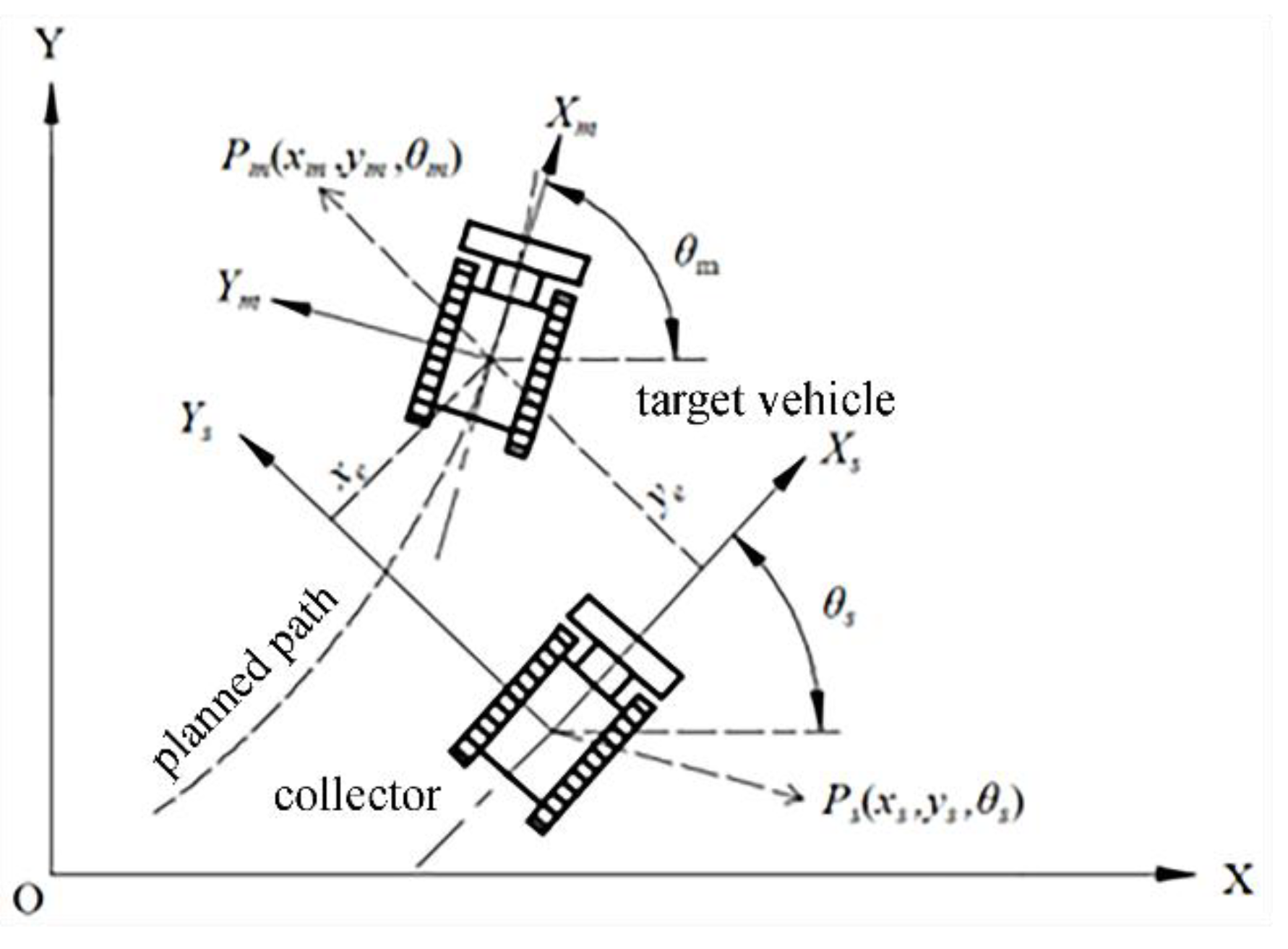
Figure 2.
Linear and Angular Velocities of a Tracked Vehicle.
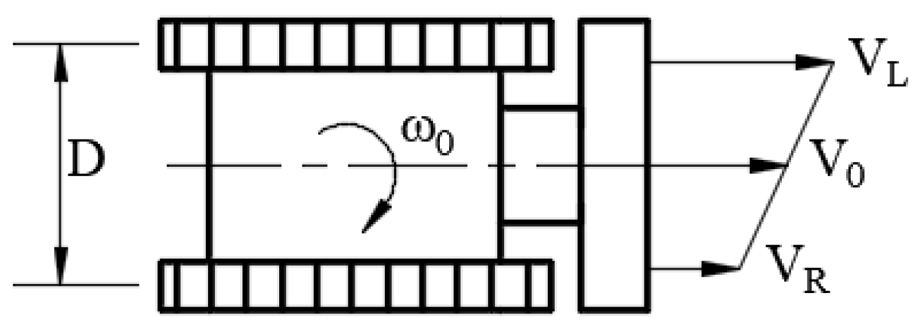
Figure 3.
Structure of the Trajectory-Tracking Control System for the Planned Path of the Deep-Sea Collector.
Figure 3.
Structure of the Trajectory-Tracking Control System for the Planned Path of the Deep-Sea Collector.
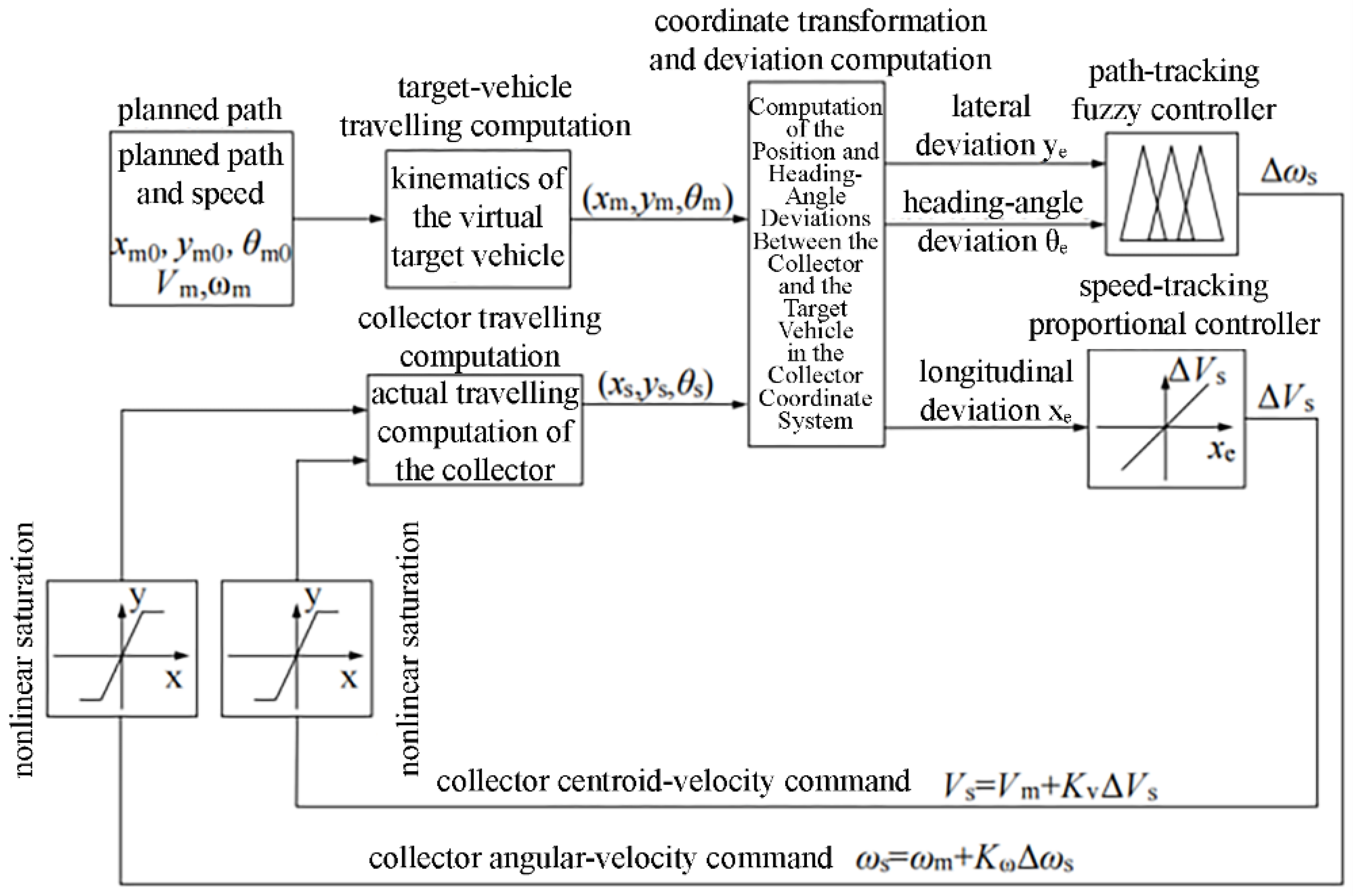
Figure 4.
Simulation results of straight-line travelling trajectory tracking.
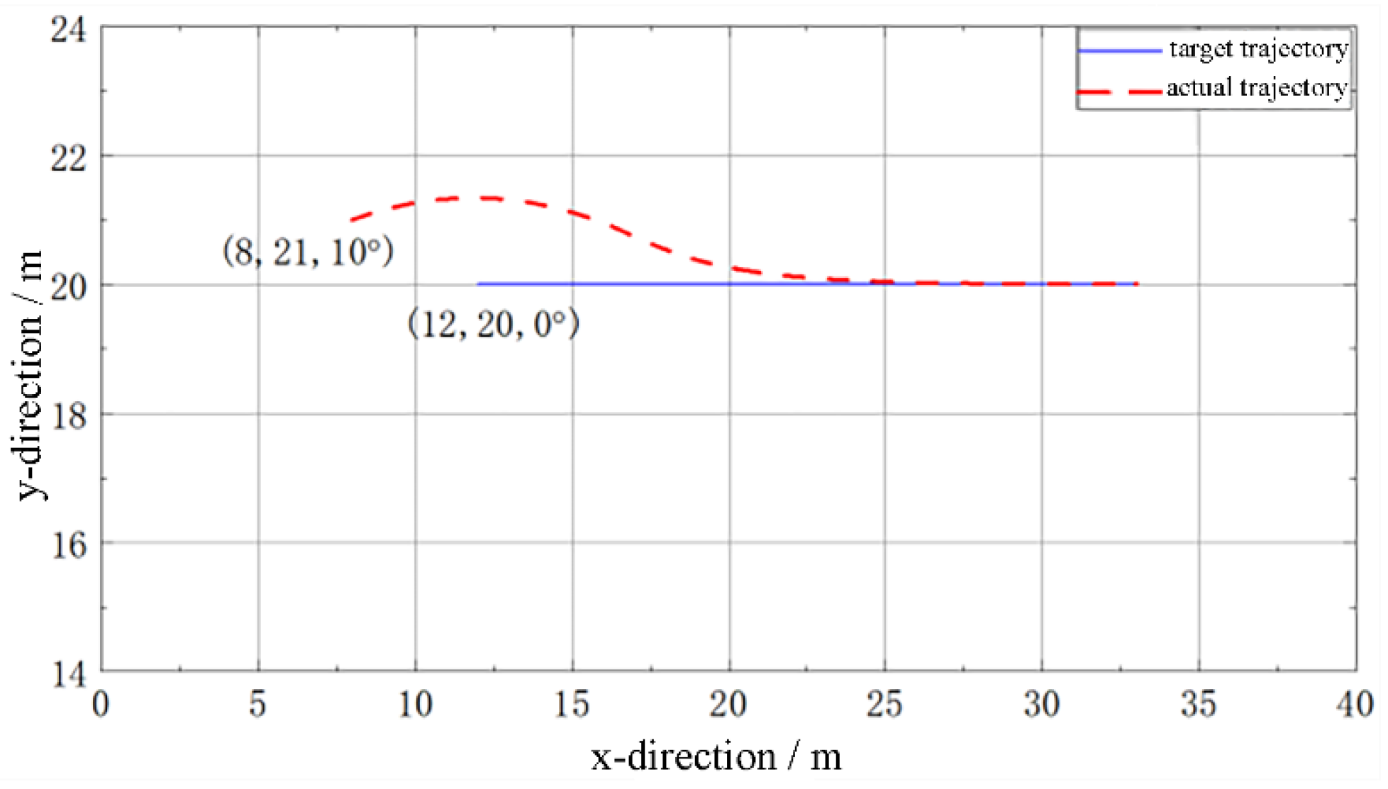
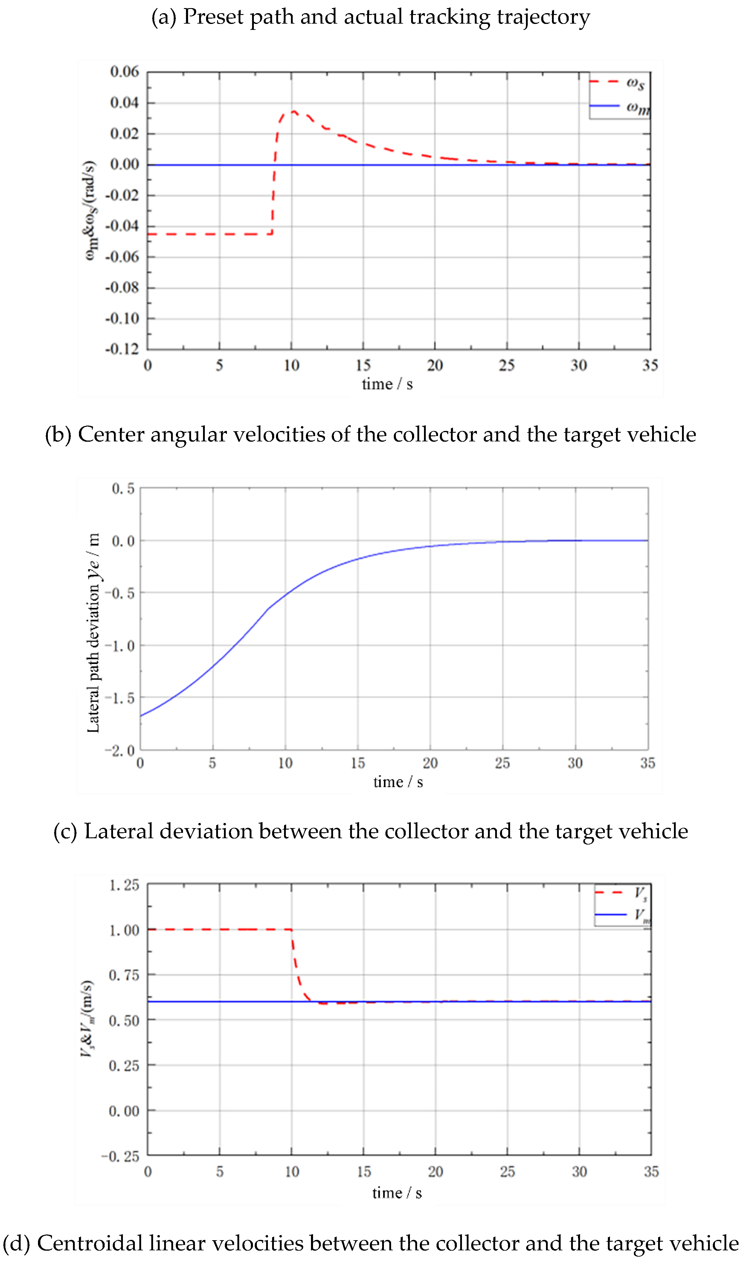
Figure 5.
Simulation results of circular-arc path trajectory tracking.
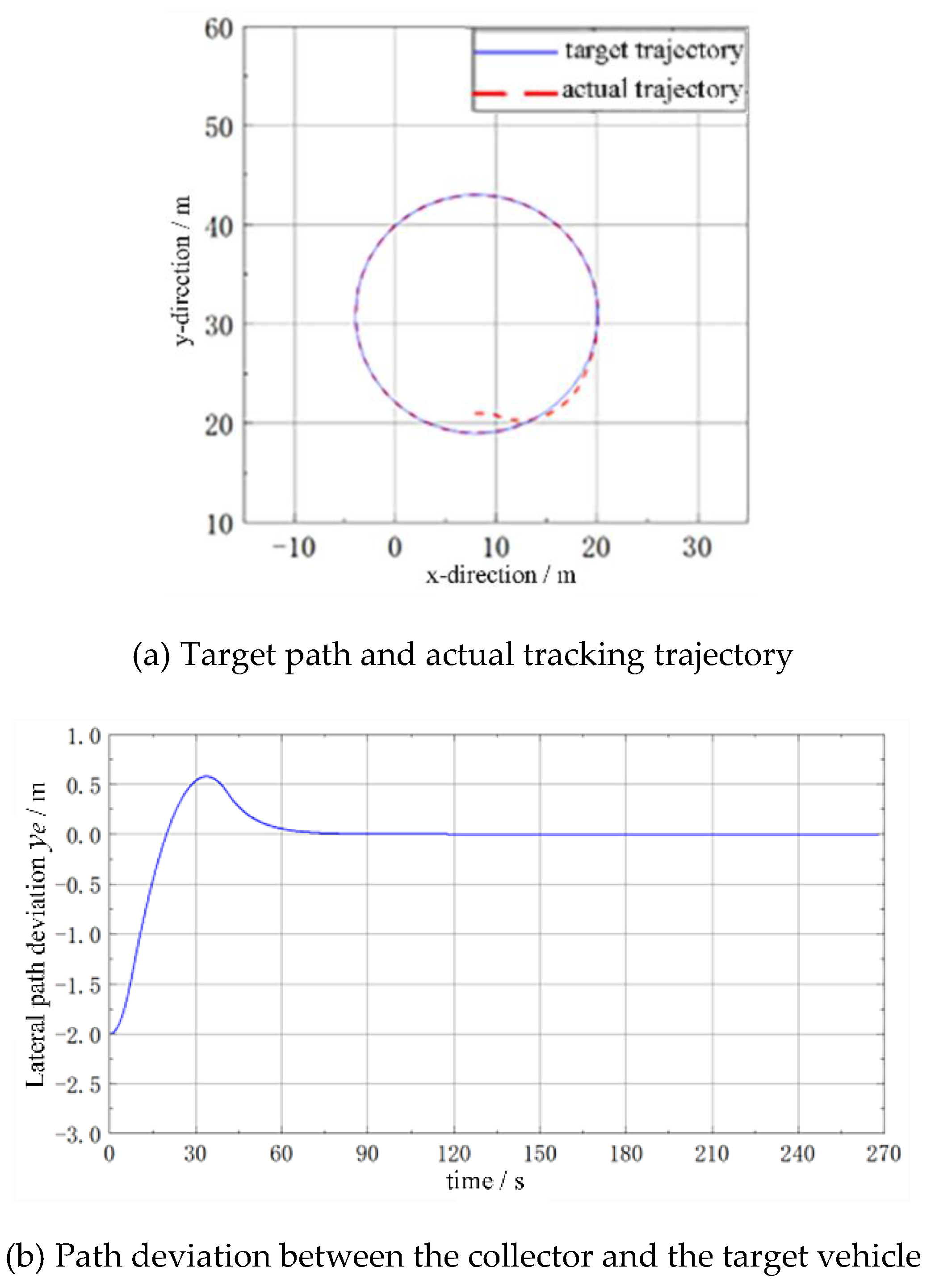
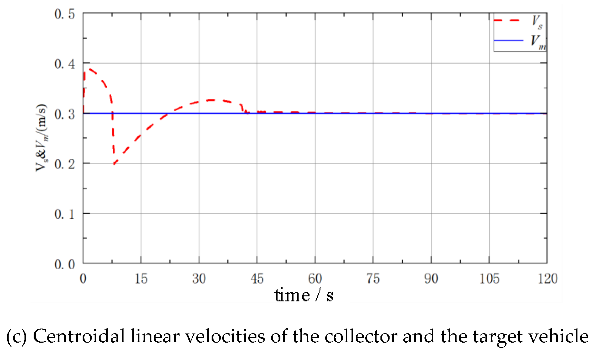
Figure 6.
A corner of the simulation experiment system.
Figure 7.
Experimental results of circular-path tracking.
Figure 8.
Designed turning-path scheme for the operational travelling of the collector.
Figure 9.
Formation of the planned path and implementation of trajectory tracking.
Figure 10.
Formation of the planned path and trajectory-tracking travelling during mining operations.
Figure 10.
Formation of the planned path and trajectory-tracking travelling during mining operations.
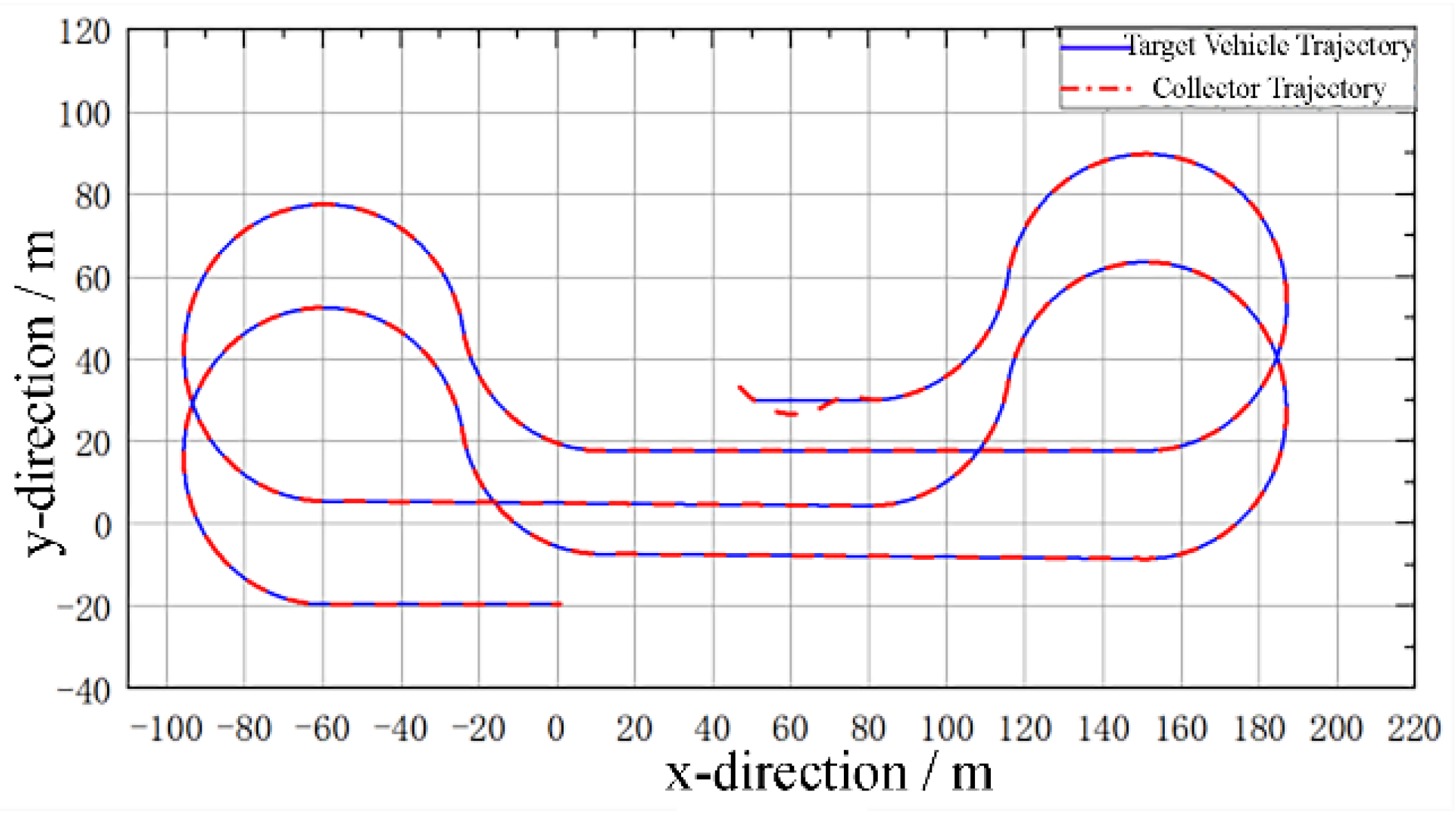

Table 1.
Fuzzy Inference Rule Table of the Angular-Velocity Controller.
| △ωs | ||||||||
| NB | NM | NS | ZE | PS | PM | PB | ||
| θ | NB | NB | NB | NM | NM | NS | NS | ZE |
| NM | NB | NM | NM | NM | NS | ZE | PS | |
| NS | NM | NM | NS | NS | ZE | PS | PS | |
| ZE | NM | NM | NS | ZE | PS | PM | PM | |
| PS | NS | NS | ZE | PS | PS | PM | PM | |
| PM | NS | ZE | PS | PM | PM | PM | PB | |
| PB | ZE | PS | PS | PM | PM | PB | PB | |
Disclaimer/Publisher’s Note: The statements, opinions and data contained in all publications are solely those of the individual author(s) and contributor(s) and not of MDPI and/or the editor(s). MDPI and/or the editor(s) disclaim responsibility for any injury to people or property resulting from any ideas, methods, instructions or products referred to in the content. |
© 2025 by the authors. Licensee MDPI, Basel, Switzerland. This article is an open access article distributed under the terms and conditions of the Creative Commons Attribution (CC BY) license (http://creativecommons.org/licenses/by/4.0/).
Copyright: This open access article is published under a Creative Commons CC BY 4.0 license, which permit the free download, distribution, and reuse, provided that the author and preprint are cited in any reuse.


