
Submitted:
26 November 2025
Posted:
27 November 2025
You are already at the latest version
Abstract
The aim of the study is to develop a qualitative-quantitative assessment method to deter-mine the resilience factor of buildings. The methodological structure is holistic, integrating different levels of indicators by cross-referencing the parameters of the Italian Minimum Environmental Criteria (CAM) technical specifications and the parameters of the building life cycle phases (LCA). The methodology involved the development of two models (CAM/LCA), which were applied to two case studies for validation: a first case study (multifunctional building) with a steel construction system, mainly dry-assembled; a second case study (laboratory building) with a prefabricated concrete construction system. The results showed that the most resilient building is the multi-purpose building, i.e., the one with a steel structure. The results obtained are consistent with scientific research in the field, highlighting the greater sustainability of the steel construction system compared to the reinforced concrete system. The models developed can be used both in the pre-operam and post-operam phases. In the first case, the assignment of dependencies to indicators defines the design guidelines, i.e., it directs professionals to adopt strategies that can have the maximum impact on achieving the initial objective (maximum resili-ence factor). In the post-operational phase, on the other hand, the models allow the resili-ence factor to be assessed at its current state, highlighting any particular critical issues and guiding operators towards possible improvement strategies. A single paragraph of about 200 words maximum. For research articles, abstracts should give a pertinent over-view of the work. We strongly encourage authors to use the following style of structured abstracts, but without headings: 1) Background: Place the question addressed in a broad context and highlight the purpose of the study; 2) Methods: briefly describe the main methods or treatments applied; 3) Results: summarize the article’s main findings; 4) Con-clusions: indicate the main conclusions or interpretations. The abstract should be an ob-jective representation of the article and it must not contain results that are not presented and substantiated in the main text and should not exaggerate the main conclusions.
Keywords:
climate change
; sustainable design
; resilient building
; building life cycle assessment
; Italian CAM
1. Introduction
The ongoing progressive climate change, whose most evident effects are global warming, manifests itself with increasingly extreme and devastating meteorological and natural events. The studies of de Wilde and Coley [1] and Lacasse et al. [2] highlight, depending on the geographical position, an increase in variability compared to the average values of the climatic parameters: temperature, precipitation, humidity, solar radiation and wind speed. These aspects require a reconsideration of the expected objectives of architectural design: sustainable and resilient buildings in the face of future extreme events. Resilience and sustainability are two sides of the same coin: sustainability tends to focus more on risk mitigation, while resilience on adaptation to risk, so in many respects they are inseparable. Resilience is the ability to react to external changes and events, returning to the original conditions; in the urban and architectural fields, resilience is spoken of due to climate change and recent environmental problems, approaching the themes of sustainability and energy saving [3].
The topic of sustainability today represents a primary objective that cuts across different production sectors. In particular, the construction industry is responsible for the extraction of 50% of raw materials in Europe, 36% of emissions, 40% of energy consumption and 21% of water consumption [4]. The recent EU Directive 2018/844 of 30 May 2018, which replaced the previous Directives 2010/31/EU on energy performance in buildings and 2012/27/EU on energy efficiency, has the objective of pursuing "the development of a sustainable, competitive, safe and decarbonised energy system". The new directive arises from the need to promote the achievement of new energy efficiency and performance objectives, namely reducing greenhouse gas emissions by at least 55% by 2030 and promoting the development of a sustainable, competitive, safe and decarbonised energy system by 2050.
In recent decades, there has been a development of methodological approaches for the evaluation of the environmental performance of buildings. Among them, the Life cycle assessment is a tool for systematically analyzing the environmental performance of products or processes throughout their life cycle, in the various phases of raw material extraction, production, construction, operation, maintenance, demolition, disposal and recovery/recycling at end-of-life.
The methodological reference, as regards the assessment of the life cycle of buildings, is represented by the standard UNI EN 15978:2011, which defines the evaluation areas of the various phases of the life cycle. As regards the evaluation of the energy efficiency and sustainability of buildings, there are various certification tools (Green Building Rating Systems).
The research therefore aimed to integrate the following levels of indicators: the objectives 11-12-13 of the 2030 Agenda, the phases of the life cycle referred to in the UNI EN 15978 standard, the technical specifications of the Italian CAM, arriving at the development of a model aimed at evaluating the level of resilience of the building.
2. State of the Art
The analysis of the state of the art was conducted by investigating the various issues that cause potential impacts and influence the resilience characteristics of the architectural work.
2.1. Sustainable Building Approach
The topic of building resilience in response to climate change has undergone significant evolution in recent years, shifting from predominantly structural approaches to integrated visions that include social, behavioral, and cultural dimensions. The literature analyzed highlights this transition through contributions ranging from technical design to the enhancement of building heritage.
Saifudeen and Mani [5] provide an overview of building adaptation strategies, focusing on passive and active solutions to mitigate climate effects. The approach is geared towards adaptive design and energy efficiency, with a strong emphasis on the integration of innovative materials and natural ventilation systems. In continuity, Kulsum [6] proposes regulatory guidelines for sustainable and resilient architecture, emphasizing the importance of local and renewable materials and strengthening the link between design and policy. On the urban side, Wu [7] introduces an original perspective, analyzing the correlation between urban design and physical activity in the context of climate change. This contribution broadens the concept of resilience to include behavioral and public health dimensions, highlighting how green spaces and pedestrian paths can promote social adaptation. Similarly, Pallubinsky et al. [8] propose an integrated human-building vision, where thermal comfort and health become central elements of resilience, shifting the focus from the structure alone to the relationship with the user. The pioneering studies by Ljubomir [9] and Katunský et al. [10] focus on structural resilience to extreme events, providing theoretical and experimental bases for design in critical conditions. This is complemented by the work of Pastori and Mazzucchelli [11], which examines the impact of extreme winds on buildings, highlighting the need to update codes and regulations to ensure safety and durability. Blandon et al. [12] introduce a cultural dimension to resilience, exploring the sustainable reuse of uninhabited buildings. This approach highlights how the enhancement of existing buildings can be an effective adaptation strategy, combining environmental sustainability and territorial identity.
In summary, the literature shows an evolution from a technical-structural focus towards a multidimensional paradigm that integrates regulatory, social, and cultural aspects. However, some gaps emerge: the lack of unified predictive models and the limited connection between physical and behavioral resilience. Opportunities for future research lie in the development of interdisciplinary frameworks that connect health, heritage, and climate adaptation, promoting holistic resilience in the built environment.
2.2. Sustainability Assessment Methods
Life Cycle Assessment (LCA), defined by ISO 14040/44 standards, is a key tool for assessing the environmental impacts throughout the life cycle of products and services. In recent years, the literature has expanded the scope of LCA, integrating it with economic and social dimensions and digital technologies to respond to sustainability challenges. This contribution summarizes and compares seven recent studies that explore these developments.
Popowicz et al. [13] analyze the impact of digital technologies on LCA, highlighting how IoT, blockchain, big data, and artificial intelligence can improve data collection and processing. The proposed framework integrates these technologies into all stages of the analysis, reducing errors and increasing the timeliness of assessments. In parallel, Lima et al. [14] explore the integration of BIM and LCA in the construction sector, demonstrating how the automation of data extraction from BIM models allows for faster and more consistent assessments, while highlighting critical issues related to interoperability. Bruno et al. [15] provide an overview of LCSA (Life Cycle Sustainability Assessment), which combines environmental LCA, Life Cycle Costing (LCC), and Social LCA (S-LCA). Four main approaches are identified: sequential analysis, graphical visualization, integration through MCDA, and combined methods. Cerchione et al. [16] explore the integration of quantitative methods (statistics, AI, BIM) with LCA and LCC methodologies, highlighting how these tools can increase the robustness of assessments and support strategic decisions. Bani et al. [17] focus on the integration of LCA in urban green infrastructure through a systematic review and meta-analysis. The study highlights the widespread adoption of environmental LCA, while economic and social dimensions remain marginal. The authors propose a unified approach to simultaneously assess environmental impacts, costs, and social benefits, in line with sustainable city objectives. Backes et al. [18] address the issue of communicating LCSA results, proposing innovative visual tools such as the “LCSA-Wheel.” Clear and concise data visualization is crucial to support stakeholders and decision-makers by reducing the complexity of multidimensional assessments. Moutik et al. [19] offer a bibliometric perspective on the evolution of LCA, highlighting exponential growth in publications (+30% per year) and greater application to bio-based materials and the circular economy. This trend confirms the importance of integrating LCA with interdisciplinary approaches and emerging technologies.
2.3. Circular Economy in Construction Sector
The circular economy is a model of self-regenerating sustainable economy that, through design, aims to extend the life cycle of products as much as possible, preserving their value, and using resources efficiently, through reuse, recycling, regeneration, but also sharing and transforming them into services, in order to minimize waste. The concepts of end of life and closing loop represent the essence of the circular economy as they express the concepts of extending the life cycle of products. The circular economy is not yet widely spread in the construction sector, but strategies and methodologies are being tested to promote its application. These include the redevelopment of existing or, in extreme cases, the use of selective demolition, with the correct management of demolition waste. It is therefore necessary that the design tends towards a “Design for disassembling” approach, that is, the design of the building also includes the planning and management of the disassembled elements.
The transition to a circular economy (CE) in the construction sector represents a strategic challenge to reduce environmental impact, optimize resource use, and promote sustainable business models. Recent literature highlights diverse approaches ranging from materials management to digitization, from regulatory policies to economic models. This contribution summarizes and compares ten key studies to outline trends, critical issues, and opportunities. Rao et al. [20] offer a comprehensive review of CE adoption in construction, identifying motivators (e.g., waste reduction, economic efficiency), barriers (regulatory gaps, high initial costs), and operational strategies. In parallel, Gasparri et al. [21] analyze 41 studies and identify 155 knowledge gaps, grouped into seven dimensions (economic, regulatory, technological, social, etc.), proposing a research framework based on three domains: product, process, and platform. Both articles emphasize the need for systemic approaches and shared metrics. Krajewska and Siewczyńska [22] focus on materials and processes, highlighting reuse and recycling practices, but also critical issues related to the quality of recycled materials. Idir et al. [23] explore the management of construction and demolition waste (CDW) in Europe, comparing international best practices and proposing measures such as regulatory harmonization and economic incentives. Firoozi and Firoozi [24] propose operational strategies such as modular design and material passports, highlighting environmental and social benefits. Jayakodi et al. [25] offer a systematic review of circular business models in the sector, proposing a ‘Circular Economy Business Model Canvas’ adapted to construction. Otasowie et al. [26] identify seven key resources for CEBM adoption, including digitization, sustainable supply chains, and specialist skills. These studies highlight how CE requires not only technological innovation, but also organizational and cultural transformations. Keles et al. [27] and Rodrigo et al. [28] analyze the role of digital technologies (BIM, IoT, blockchain, digital twins) in supporting CE throughout the building life cycle. Applications include material traceability, flow optimization, and waste prediction. However, challenges related to interoperability, data security, and operator training emerge. Ibe et al. [29] offer a review of material management strategies, highlighting practices such as “design for deconstruction,” modularity, and reverse logistics. These strategies prove effective in reducing waste and costs, but require coordination between actors and digital tools for traceability.
2.4. Environmental Pollution of the Construction Sector and Related Risks
The construction sector is one of the largest consumers of natural resources and energy, contributing significantly to greenhouse gas emissions and air pollution. Recent literature highlights how the production, construction, and demolition phases of materials generate significant environmental impacts, with implications for human health and climate change. This paper critically analyzes five key studies to outline trends, critical issues, and mitigation opportunities.
Wieser et al. [30] address the issue of air pollution in the construction sector, highlighting how fine particulate matter (PM) and volatile organic compounds (VOCs) pose significant risks to the health of workers and users. The study emphasizes the need for preventive strategies, such as efficient ventilation systems and low-emission materials, but notes a lack of research on the construction and demolition phases compared to building use. Wang et al. [31] provide a comprehensive review of CO₂ emissions throughout the life cycle of buildings, identifying material production (cement, steel), transportation, and construction as the main contributors. The study proposes reduction approaches based on alternative materials, energy efficiency, and the integration of renewable technologies, but highlights gaps in assessments related to demolition and waste management. Zhao et al. [32] analyze methods for accounting for emissions in the construction sector, highlighting the fragmentation between macro-scale (national) and micro-scale (building/material) studies, with little attention paid to the urban scale. Furthermore, critical issues emerge in the definition of system boundaries, which often exclude phases such as demolition and recycling, limiting the completeness of the analyses. The UNEP report [33] emphasizes the impact of construction materials, which account for about one-third of global emissions. Cement, steel, and aluminum are identified as carbon hotspots, requiring decarbonization strategies, the use of regenerative materials, and global policies to reduce the extraction of primary resources. The document highlights the urgency of international standards and monitoring along supply chains. Aparna and Baskar [34] offer a scientometric overview of the application of Life Cycle Assessment (LCA) in the construction sector, showing significant growth in publications and the effectiveness of LCA in identifying hotspots of emissions and resource consumption. However, the study notes limited integration of LCA into everyday design practices and the need for more accessible decision-making tools.
2.5. Off-Site Construction
In the last century, a first response to improving the performance of a building was given by prefabrication, but only recent innovations in manufacturing processes have led to a significant expansion in the use of prefabricated components, assembled on site. Off-site construction, prefabrication and other modern construction methods reduce the intensity of work on site to localize it mainly in the factory, allowing a reorganization of technologies and processes aimed at greater efficiency and quality.
Off-site construction (OSC) is one of the main strategies for addressing the challenges of sustainability, productivity, and digitalization in the construction sector. However, the literature highlights heterogeneous and sometimes contradictory approaches. The articles analyzed offer complementary perspectives: from criticism of the discourse on sustainability (Rathnasinghe et al., 2024 [35]) to barriers to adoption (Olayiwola et al., 2025 [36]), to the opportunities offered by digital technologies and AI (Wang et al., 2020 [37]; Najafzadeh & Yeganeh, 2025 [38]). Rathnasinghe et al. [35] also highlight how the discourse on sustainability in CSOs is often rhetorical, with little attention to measurability and consistency between objectives and practices. Their scientometric analysis shows a fragmentation of the debate. Di Ruocco et al. (2018, 2019) [39,40] address the issue from a technical perspective, proposing CO₂ reduction thresholds and embodied energy mitigation strategies. These studies bridge the gap between theory and practice by providing operational tools for assessing the environmental impact of building systems. While Rathnasinghe denounces the vagueness of the discourse, Di Ruocco proposes quantitative approaches, suggesting that sustainability requires a shift from narrative to measurement.
Olayiwola et al. [36], through a PESTEL analysis, identify political, economic, and technological barriers that slow down the adoption of OSC. The systematic review highlights the complexity of the regulatory environment and cultural resistance. Broadhead et al. [41] confirm the need for integrated strategies to overcome organizational and supply chain barriers, albeit with a more descriptive approach. Both studies converge on the importance of support and training policies, but Olayiwola [36] offers a more robust analytical framework (PESTEL), useful for strategic decision-making. Manouchehri et al. [42] propose a process-oriented model to improve productivity throughout the life cycle, highlighting the interdependence between design, production, and logistics. Jang et al. [43] map the key knowledge for successful OSC projects, suggesting that productivity is linked to integrated skills management and digitization. Productivity is not just a matter of operational efficiency, but of knowledge governance and process integration. Wang et al. [37] and Cheng et al. [44] analyze the state of digital technology adoption, highlighting the role of BIM, IoT, and augmented reality as drivers of innovation. Najafzadeh & Yeganeh [38] explore the use of Digital Twins and AI for predictive management and simulation. Tan et al. [45] introduce the concept of digital DfMA, emphasizing modularity as the key to integrating product and process. Parracho et al. [46] offer a systematic overview of smart and sustainable innovations, outlining future scenarios for modular construction. Digitalization emerges as a cross-cutting factor that enables sustainability and productivity, but requires investment in interoperability and skills.
A comparison of the articles reveals an evolutionary trajectory for OSC: from a phase of rhetoric on sustainability to a data-driven perspective, supported by digital technologies and integrated governance models. However, regulatory and cultural barriers persist, requiring systemic approaches (PESTEL) and training strategies. In summary, the future of OSC depends on the ability to combine technological innovation, sustainability measurability, and supportive policies.
2.6. Buildings' Response to Climate Change: Resilience and Adaptation
Climate change poses a dual challenge for the construction sector: adapting to new conditions and withstanding extreme events. The literature distinguishes between two key concepts:
-Adaptation: the process of modification to reduce vulnerability and exploit opportunities.
-Resilience: the ability to absorb, recover, and maintain essential functions after adverse events.
Saifudeen & Mani [47] provide an overview of adaptation strategies, distinguishing between passive (orientation, natural ventilation) and active (smart technologies, innovative materials) solutions. They emphasize the importance of regional climate assessments and updated building codes. Tajuddeen & Sajjadian [48], in a systematic review, highlight how adaptation requires integration between energy efficiency, thermal comfort, and social resilience. They propose a holistic approach that also considers governance and urban planning. EU Technical Guidance [49] translates the concept of adaptation into operational criteria: vulnerability assessment, checklists for interventions, and guidelines for classifying resilient buildings. This document is crucial for standardization at the European level. The studies agree on the need for a multi-level approach, but while Saifudeen and Tajuddeen focus on technical and design strategies, the EU guidance introduces regulatory tools and applicable metrics. Bouramdane [50] explores resilience as a dynamic function linked to the ability to absorb shocks and restore functions. He proposes metrics for assessing structural robustness, operational flexibility, and integration with mitigation strategies. Wang & Ramakrishnan [51] address resilience and adaptation jointly, highlighting thermal comfort, material durability, and risk management as key elements. They introduce the concept of design resilience, which anticipates future climate scenarios. Chamindi Malalgoda et al. [52] adopt a transdisciplinary approach, including social and educational aspects. Resilience is not only technical but also cultural, requiring innovative skills and learning processes. Resilience emerges as a broader and more dynamic concept than adaptation, including rapid response and recovery capabilities, in addition to physical robustness. The articles converge on the need for integration between resilience and adaptation, with regulatory tools (EU Guidance) and transdisciplinary approaches (Malalgoda et al.) as levers for transforming the sector.
The comparison highlights that the response of buildings to climate change cannot be limited to isolated technical interventions. An ecosystem of strategies is needed that combines:
-Resilience metrics to assess robustness and recovery capacity.
-Adaptation processes to reduce vulnerability and ensure comfort.
-Standards and guidelines to standardize practices and promote scalability.
-Training and governance to integrate social and cultural dimensions.
In summary, resilience and adaptation are not alternative concepts, but complementary ones, and their integration is the key to long-term sustainable buildings and cities.
3. Materials and Methods
Agenda 2030 is the document adopted by the governments of the 193 member countries of the United Nations on the occasion of the Sustainable Development Summit of 25-27 September 2015, which includes 17 Sustainable Development Goals (SDGs) and 169 targets to be achieved by 2030 [53]. The sustainable development goals of Agenda 2030 are conceived as an attempt to address all aspects of sustainability and resilience, to remedy the negative aspects of globalization, such as the irrational use of non-renewable global resources, population growth and negative impacts on the environment and the planetary biosphere. Agenda 2030 launches a challenge of complexity: since the three dimensions of sustainable development (economic, environmental and social) are closely related to each other, each objective cannot be considered independently but must be pursued on the basis of a systemic approach, which takes into account the mutual interrelationships and does not have negative repercussions on other spheres of development. Only the integrated growth of all three components will allow the achievement of sustainable development.
ISO 15392:2019, “Sustainability in buildings and civil engineering works - General principles”, establishes principles of sustainability in buildings and construction. It provides a common language for all stakeholders in the sector, from designers and manufacturers to regulators and consumers, which can be used as a basis for communication and for derived evaluation criteria. Improvements to the new version include additional information on the general principles, the application of the principles as they relate to the three pillars of sustainability (economic, social and environmental) as well as the introduction of new concepts such as resilience.
The performance requirement regulation UNI 10838:1999 determines quality through the definition of what is wanted from the building object and not how the building object is wanted. It is based on:
-Needs: explanation of requests, needs;
-Requirements: request addressed to a specific building element to possess operating characteristics such as to satisfy certain needs;
-Performance: describes the behavior of a given component or building element when used.
The UNI 8289:1981 and UNI 11277:2007 standards identify 8 fundamental classes of needs whose satisfaction defines the quality of the product: safety, well-being, hygiene and health of users, usability, appearance, management, integrability, environmental protection and rational use of resources.
The UNI 8290-1:1981 standard defines the technological system, identify technological unit classes, technological units and classes of technical elements, and the criteria for identifying the technical elements; UNI 8290-2:1983 defines the 63 requirements and the analysis criteria; finally the UNI 8290-3:1987defines and analyses the agents and the actions which in operating conditions are exercised on building system.
The European Standard UNI EN 15978:2011 [54] specifies the calculation method, based on life cycle analysis (LCA) and other quantified environmental information, to assess the environmental performance of a building, and provides the means for reporting and communicating the outcome of the assessment. The standard is applicable to new and existing buildings and renovation projects. The assessment approach covers all phases of the life cycle of the building and is based on data obtained from environmental product declarations (EPDs), their "information modules" (prEN 15804) and other information necessary and relevant to carry out the assessment. The assessment includes all products, processes and services related to construction, used during the life cycle of the building (Figure 1).
The Minimum Environmental Criteria (CAM) were adopted in Italy by Decree of the Minister of the Environment, Land and Sea Protection (Ministerial Decree 23 Giugno 2022 "Assignment of design services and works for the new construction, renovation and maintenance of public buildings") [55,56]. They define the environmental requirements for the various phases of the purchasing process, aimed at identifying the best design solution, product or service from an environmental perspective throughout the life cycle, taking into account market availability.
In Italy, the adoption of CAM is regulated by art. 34 of the Public Contracts Code (Legislative Decree 50/2016), which has made its application mandatory by all contracting authorities.
In addition to the enhancement of environmental quality and compliance with social criteria, the application of the Minimum Environmental Criteria also responds to the need of the Public Administration to rationalize its consumption, reducing expenditure where possible.
The structure and procedure for defining CAMs facilitates the task of contracting authorities in adopting and implementing a GPP (Green Public Procurement) policy.
The structure of the CAM is represented in the following figure.
The current scenario, as described in the previous chapters, requires the experimentation of methodologies aimed at identifying the nature and extent of building vulnerabilities, according to a multitasking/integrated approach, in order to evaluate their level of resilience, in function of their timely and effective response to climate change.
In literature there are several tools and evaluation methods in this regard, however, a gap in this sector seems to be the lack of a quantitative methodology, capable of measuring the actual capacity of a building to be resilient and adaptive to climate changes and extreme events.
The research therefore involves the development of a methodology that allows the qualitative and quantitative evaluation of the resilience of buildings both in the design phase, in the construction phase and in the operation phase.
The methodological approach includes 8 phases:
-Definition of the scope of investigation/macro-objectives: principles of sustainability, Agenda 2030
-Defining micro-objectives: targets and indicator categories
-Identification of indicators: sensitive technological units
-Definition of sub-indicators: areas of investigation and life cycle phases
-Definition of weights/performance thresholds
-Assessment of the resilience factor of buildings
-Application of the method to case studies
-Identifying improvement strategies
The first phase starts with the identification of the main macro-objectives that drive this work: sustainable development in the environmental, social-political and economic dimensions and the objectives of the 2030 Agenda.
The Agenda 2030 objectives identified for the purposes of this work are:
-Goal 11 Sustainable cities and communities: Make cities and human settlements inclusive, safe, resilient and sustainable;
-Goal 12 Responsible consumption and production: ensure sustainable consumption and production patterns;
-Goal 13 Climate action: Take urgent action to combat climate change and its impacts.
Subsequently, the environmental, social-political and economic aspects were analyzed for each objective, thus defining goals that would allow the identification of categories of indicators. Therefore, 16 categories of indicators were identified and for each of them, the focus was on sensitive technological units, technical specifications and award criteria of the CAM.
The following table shows the model developed for the methodological development.

Table 1.
Objectives, targets and categories of indicators .
| Macro systems (ISO 15392) |
Objectives (Agenda 2030) | Milestones | Indicator Categories |
|---|---|---|---|
| ENVIRONMENTAL | Making cities and human settlements inclusive, safe, resilient and sustainable | Promote off-site construction | Modular design |
| Maintain or restore the functionality of a building after damage | Modular design | ||
| Minimization of waste from demolition operations | Conservative design/Existing recovery | ||
| Decarbonisation of construction processes | NZEB Design | ||
| Creating healthy and comfortable spaces | Multi-scale/integrated design | ||
| Ensuring sustainable consumption and production patterns | Sustainable management and efficient use of natural resources | NZEB Design | |
| Substantially reduce waste generation through prevention, reduction, recycling and reuse | Design using a circular BIM-LCA approach | ||
| Ensure water saving and system efficiency | Design of water recovery and reuse systems | ||
| Use of eco-friendly materials and recycled content | Eco-design (CAM) | ||
| Take urgent action to combat climate change and its impacts | Reduction of heat islands | Eco-friendly design / SMART plant design | |
| Improving ambient air quality | |||
| Protection from extreme temperatures | |||
| Drought and flood protection | Multi-scale/integrated design | ||
| Protection from sea level rise and storm surge | |||
| Protection from hurricanes and severe storms | Aerodynamic design | ||
| Fire protection | Fire safety design | ||
| Protection from seismic activity | Anti-seismic design | ||
| SOCIAL-POLITICAL | Making cities and human settlements inclusive, safe, resilient and sustainable | Ensure access for all to adequate, safe and affordable housing and basic services | Elimination of architectural barriers |
| Strengthen inclusive urbanization and the capacity to plan and manage participatory, integrated and sustainable human settlements | Participatory design | ||
| Guaranteeing a welcome for immigrants and asylum seekers | Inclusive/adaptive design | ||
| Creating safe, shared and inclusive public spaces | Inclusive/adaptive design | ||
| Ensuring sustainable consumption and production patterns | Adaptability and functional flexibility | Modular design | |
| Engage with neighborhood groups and help them develop a sustainable future vision for their community | Participatory design | ||
| Promote sustainable public procurement practices, in accordance with national policies and priorities | Sustainable Tenders (CAM - PAN GPP) | ||
| Take urgent action to combat climate change and its impacts | Integrate climate change measures into national policies, strategies and planning | Urban and Territorial Planning | |
| Map areas that need improvement, such as areas most exposed to natural disasters | Urban and Territorial Planning | ||
| Increase effective capacity for planning and management of climate change interventions | Urban and Territorial Planning | ||
| ECONOMIC | Making cities and human settlements inclusive, safe, resilient and sustainable | Reduction of direct economic losses caused by disasters | Modular design |
| Reduction of construction, use and end-of-life costs of buildings | Economic evaluation of interventions using the LCC approach | ||
| Ensuring sustainable consumption and production patterns | Rationalize inefficient fossil fuel subsidies that encourage waste | NZEB Design | |
| Promotion of the circular economy with consequent dematerialization of the economy | Design using a circular BIM-LCA approach | ||
| Take urgent action to combat climate change and its impacts | Promoting the economy based on renewable energy sources | Multi-scale/integrated design |
3.1. Assigning Weights to Indicators
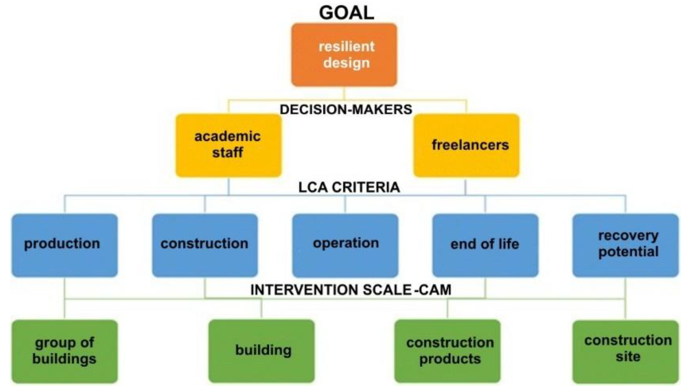
The assignment of weights to the relative indicators was carried out by adopting a multiple criteria decision-making process (MCDM), through the involvement of operators in the sector to whom suitable questionnaires were administered.
The people identified for the evaluation and assignment of weights to the relevant parameters were chosen with these criteria:
- Teaching staff and academic researchers;
- Freelancers.
As regards the selection of academic staff, first and second level professors (full and associate professors) and researchers belonging to university institutions were identified, working in the disciplines related to the topics under examination: technical architecture, environmental impact assessment, urban planning, environmental technical physics, water resources management, energy and environmental sustainability and economic evaluation of projects.
As regards the selection of freelancers, civil and building engineers and architects registered in the Professional Register of the most populated provinces of Italy (Rome, Milan, Naples, Turin, Palermo, Brescia, Bari, Catania, Bergamo) were invited, requiring among their work experiences:
-at least one in the field of energy and environmental sustainability protocols for buildings (Engineer Architecture Construction (EAC) freelancer)
-experience in the field of urban and territorial planning with particular reference to resilience dynamics (Urban Designer freelancer)
The criteria for the evaluation of the indicators are expressed in terms of impacts in the various life cycle phases (LCA) identified by the European Standard UNI EN 15978.
The attributes were identified on the basis of the technical specifications present in the CAMs which refer to: Building groups, Buildings, Building components and Construction site.
Specifically, 16 categories of indicators have been identified that concern the environmental, social-political and economic aspects of sustainable design and for each category sensitive indicators have been identified with reference to the technological aspects (UNI 8290 standard) and to the qualitative-quantitative parameters referred to in the Minimum Environmental Criteria (CAM) for a total of 120 indicators.
Figure 2.
Multi-criteria approach scheme
3.2. Definition of the Questionnaire to Be Administered to the Interested Parties
For the objective application of the method, questionnaires were administered to the interested parties identified with the criteria expressed above. The objective of the questionnaire is to assign scores to the aforementioned indicators using a rating scale in order to finally extrapolate the weight to be attributed to each indicator based on the relative importance that it must have for each criterion. The respective score according to a scale from 0 to 3 must be assigned based on the potential impact of the specific indicator with respect to the different life stages identified in the European regulation UNI EN 15978, according to the multi-scalar approach of the CAM.
Table 2.
Rating scale for indicators.
| Score | Rating |
|---|---|
| 0 | None |
| 1 | Minimum |
| 2 | Good |
| 3 | Excellent |
The assignment of scores to the respective indicators must take into account the level of compliance of the indicator with respect to the threshold ratings defined as follows:
PRODUCTION PHASE
Minimization of CO2eq emissions through:
- reduction of the quantities of extraction of virgin raw materials;
- use of EEV vehicles for transport from the quarry to the industry;
- reduction of resources needed for the industrial phase of production
CONSTRUCTION PHASE
Design oriented towards the concept of eco-effectiveness, through:
- construction designed to allow for multiple life cycles;
- predisposition of the construction to the up-cycling strategy, i.e. adoption of construction systems that mainly allow the reuse of components at the end of their life;
- flexibility of the technological unit, or of the single building component, for use, in the subsequent life cycle, with a different destination than the previous one
EXERCISE PHASE
Preparation of the construction/plant system, in terms of:
- adaptation to climate change;
- flexibility with respect to changes in context;
- internal functional flexibility;
- reduction of use of natural resources (energy and water resources);
- reduction of CO2eq emissions and pollutants;
- easy maintenance and/or component replacement operations
END OF LIFE PHASE
Design oriented towards the concept of deconstruction, through:
- minimization of demolition operations;
- preparation of the construction system for selective demolition operations;
- exclusive prevalence of disassembly/disassembly operations of technological units and their respective components
RECOVERY POTENTIAL
Preparation of the technological unit / componentconstruction to operations of:
- reuse with the same previous destination;
- reuse with a different purpose from the previous one, through slight adaptations;
- recycling, through transformation;
- landfill / recovery
Table 3.
Example sheet for the evaluation of an indicator
| Indicator Category | Modular Design | |||||
|---|---|---|---|---|---|---|
| Type of Indicator | Foundation Structure | |||||
| Impact on life cycle phases (EN 15978:2011) | Impact on the technical specifications of the minimum basic environmental criteria (DM 23/06/2022) | Weight assignment | ||||
| Production phase | Groups of buildings (art. 2.3) | 0 | 1 | 2 | 3 | |
| Buildings (art. 2.4) | 0 | 1 | 2 | 3 | ||
| Building components (art. 2.5) | 0 | 1 | 2 | 3 | ||
| Construction site (art. 2.6) | 0 | 1 | 2 | 3 | ||
| Construction phase | Groups of buildings (art. 2.3) | 0 | 1 | 2 | 3 | |
| Buildings (art. 2.4) | 0 | 1 | 2 | 3 | ||
| Building components (art. 2.5) | 0 | 1 | 2 | 3 | ||
| Construction site (art. 2.6) | 0 | 1 | 2 | 3 | ||
| Exercise phase | Groups of buildings (art. 2.3) | 0 | 1 | 2 | 3 | |
| Buildings (art. 2.4) | 0 | 1 | 2 | 3 | ||
| Building components (art. 2.5) | 0 | 1 | 2 | 3 | ||
| Construction site (art. 2.6) | 0 | 1 | 2 | 3 | ||
| End of life phase | Groups of buildings (art. 2.3) | 0 | 1 | 2 | 3 | |
| Buildings (art. 2.4) | 0 | 1 | 2 | 3 | ||
| Building components (art. 2.5) | 0 | 1 | 2 | 3 | ||
| Construction site (art. 2.6) | 0 | 1 | 2 | 3 | ||
| Benefits beyond the system | Groups of buildings (art. 2.3) | 0 | 1 | 2 | 3 | |
| Buildings (art. 2.4) | 0 | 1 | 2 | 3 | ||
| Building components (art. 2.5) | 0 | 1 | 2 | 3 | ||
| Construction site (art. 2.6) | 0 | 1 | 2 | 3 | ||
3.3. Data Processing and Determination of Indicator Weights
Once all the questionnaires had been collected, the evaluation was carried out by building two tables identical to the one given via the questionnaire and averaging all the scores obtained for each indicator, in each phase of the life cycle and for each area of application.
Model based on the application areas of CAM
Subsequently, following the subdivision proposed by the CAM, the average of the scores obtained for each indicator for each application area in the various phases of the life cycle was calculated. In this way, each indicator will have 4 different average scores depending on the application area and the sum of the scores achieved was calculated for each area.
The last step involved calculating the weights of each indicator for each area of investigation, for which the average score of each indicator was divided by the total sum of the scores and then multiplied by 100.
=Indicator weight
=Score-average indicator
=Sum of average indicator scores
In this way the sum of the weights of all the indicators will give a value of 100.
Table 4.
Assignment of weights to indicators with respect to the CAM investigation areas.
| Indicator Categories | Strategic approach | Indicators | Weights in relation to the areas of application of CAM | |||
|---|---|---|---|---|---|---|
| Building Group | Buildings | Building components | Worksite | |||
| 1. Modular design | Passive strategies | Foundation structures | 0.14 | 0.89 | 1.14 | 0.95 |
| Elevation structures | 0.19 | 0.88 | 1.16 | 1.03 | ||
| Vertical closures (opaque and transparent) | 0.19 | 0.85 | 1.13 | 0.94 | ||
| Horizontal closures | 0.18 | 0.84 | 1.08 | 0.91 | ||
| Internal partitions | 0.16 | 0.80 | 1.07 | 0.93 | ||
| Active strategies | Plant components | 0.19 | 0.94 | 1.20 | 0.99 | |
| 2. Conservative design/ Existing recovery | Passive strategies | Disassembly and selective demolition | 0.19 | 0.99 | 1.26 | 1.42 |
| Load-bearing structure (wet system) | 0.11 | 0.79 | 1.02 | 1.06 | ||
| Load-bearing structure (dry system) | 0.11 | 0.89 | 1.16 | 1.22 | ||
| Vertical closures (wet system) | 0.13 | 0.78 | 1.01 | 1.05 | ||
| Vertical closures (dry system) | 0.13 | 0.85 | 1.12 | 1.18 | ||
| Internal partitions (wet system) | 0.10 | 0.68 | 0.89 | 0.92 | ||
| Internal partitions (dry system) | 0.10 | 0.75 | 0.99 | 1.03 | ||
| Insulation of opaque closures | 0.11 | 0.92 | 1.20 | 1.22 | ||
| 3. Design using a circular BIM-LCA approach | Passive strategies | Secondary raw material recovered or recycled | 0.86 | 0.99 | 1.26 | 1.32 |
| Materials derived from renewable raw materials | 0.86 | 1.07 | 1.37 | 1.42 | ||
| Materials with DAP/EPD certification (Environmental Product Declaration) | 0.81 | 1.06 | 1.36 | 1.39 | ||
| Selective demolition and recycling of excavated materials and construction and demolition waste (C&D) | 0.28 | 1.12 | 1.42 | 1.52 | ||
| Predictive and scheduled maintenance plan for the work | 0.14 | 0.97 | 1.21 | 1.18 | ||
| External closures and internal dry partitions | 0.10 | 0.79 | 1.03 | 1.02 | ||
| 4. NZEB Design | Passive strategies | Solar orientation | 0.85 | 0.78 | 0.97 | 0.74 |
| Shading with plant or architectural elements | 0.90 | 0.88 | 1.12 | 0.87 | ||
| Eco-friendly materials with low embodied carbon content | 0.86 | 1.02 | 1.27 | 1.16 | ||
| Insulation of opaque and transparent vertical closures | 0.76 | 0.90 | 1.14 | 0.89 | ||
| Sun protection devices | 0.74 | 0.97 | 1.21 | 1.00 | ||
| Natural ventilation systems | 0.76 | 0.97 | 1.21 | 0.91 | ||
| Active strategies | Heating and air conditioning systems | 0.64 | 0.82 | 1.02 | 0.82 | |
| Systems powered by renewable sources for the production of electricity and domestic hot water | 0.73 | 0.98 | 1.23 | 0.93 | ||
| Controlled mechanical ventilation systems | 0.61 | 0.82 | 1.02 | 0.79 | ||
| Flow reduction systems, flow control systems, water temperature control systems | 0.63 | 0.82 | 1.02 | 0.81 | ||
| Low water consumption sanitary appliances | 0.68 | 0.85 | 1.06 | 0.81 | ||
| High efficiency alternative systems (high efficiency co/trigeneration, centralized heat pumps) | 0.73 | 0.95 | 1.18 | 0.92 | ||
| Mixed strategies | Transparent vertical closures integrated with photovoltaic | 0.73 | 0.98 | 1.23 | 0.95 | |
| Integrated panels for external closures (BiPV) | 0.65 | 0.90 | 1.14 | 0.86 | ||
|
5. Eco-friendly design (CAM, SMART plant design) |
Passive strategies | Vehicles of the EEV (Improved Ecological Vehicle) category | 0.88 | 0.58 | 0.74 | 0.83 |
| Visual and noise shielding on construction sites | 0.25 | 0.62 | 0.76 | 1.12 | ||
| Green or cold upper and vertical closures | 0.25 | 0.93 | 1.17 | 0.67 | ||
| Highly reflective opaque external closures (for roofing and casings) | 0.20 | 0.88 | 1.08 | 0.62 | ||
| Low-emissivity transparent external closures | 0.20 | 0.92 | 1.14 | 0.65 | ||
| Ecological thermal and acoustic insulation of opaque vertical closures and internal partitions | 0.16 | 1.04 | 1.29 | 0.71 | ||
| Natural lighting | 0.31 | 0.96 | 1.17 | 0.63 | ||
| Flooring and coverings with low VOC (volatile organic compound) release | 0.20 | 0.95 | 1.18 | 0.67 | ||
| Pollutant protection systems | 0.24 | 1.00 | 1.25 | 0.68 | ||
| Storage system for vital energy self-sufficiency in the event of disasters | 0.25 | 0.87 | 1.06 | 0.58 | ||
| Active strategies | Air quality control systems (during construction, building and occupation phases) | 0.19 | 0.95 | 1.16 | 0.66 | |
| Lighting control and integration systems | 0.16 | 0.87 | 1.06 | 0.59 | ||
| Air flow and CO2 monitoring systems | 0.18 | 0.98 | 1.21 | 0.67 | ||
| Energy consumption monitoring system | 0.16 | 1.01 | 1.25 | 0.68 | ||
| Home automation systems | 0.18 | 0.86 | 1.06 | 0.60 | ||
| 6. Aerodynamic design | Passive strategies | Compact building shape (curved facades) | 0.43 | 0.39 | 0.49 | 0.42 |
| Elevation structures | 0.43 | 0.78 | 0.99 | 0.96 | ||
| Coverings | 0.43 | 0.79 | 1.00 | 0.98 | ||
| Opaque vertical closures | 0.46 | 0.79 | 1.00 | 0.95 | ||
| Transparent vertical closures | 0.44 | 0.77 | 0.97 | 0.94 | ||
| 7. Design of water recovery and reuse systems | Passive strategies | Permeable flooring | 1.57 | 0.93 | 0.18 | 0.67 |
| Infiltration grates and channels | 1.40 | 0.84 | 0.19 | 0.58 | ||
| Arrangement of green areas | 1.38 | 0.82 | 0.17 | 0.54 | ||
| Rainwater collection tank | 1.72 | 1.02 | 0.19 | 0.68 | ||
| Wastewater storage tanks | 1.50 | 0.89 | 0.19 | 0.60 | ||
| Accumulation tanks for purified water | 1.67 | 0.99 | 0.20 | 0.68 | ||
| Toilet storage tanks | 1.40 | 0.84 | 0.21 | 0.61 | ||
| Active strategies | Rainwater filtration and purification system | 1.77 | 1.05 | 0.20 | 0.76 | |
| Irrigation systems for green areas | 1.45 | 0.87 | 0.18 | 0.59 | ||
| Wastewater treatment plant | 1.67 | 0.99 | 0.18 | 0.69 | ||
| 8. Fire safety design | Passive strategies | Fireproofing treatment for structural elements | 1.03 | 0.75 | 0.93 | 0.33 |
| Smoke-proof filter compartment | 0.97 | 0.70 | 0.88 | 0.32 | ||
| Insulation of internal closures and partitions | 0.92 | 0.67 | 0.83 | 0.32 | ||
| External vertical connections (fire escapes) | 1.19 | 0.88 | 1.10 | 0.40 | ||
| Compensatory water supply tank | 1.28 | 0.92 | 1.15 | 0.45 | ||
| Storage tank for waste water for auxiliary fire-fighting system supply | 1.24 | 0.91 | 1.14 | 0.45 | ||
| Active strategies | Detection and alarm systems | 0.93 | 0.67 | 0.84 | 0.28 | |
| Oxygen reduction systems | 0.94 | 0.67 | 0.84 | 0.31 | ||
| Fire water system | 1.03 | 0.75 | 0.93 | 0.39 | ||
| Automatic fire extinguishing systems | 0.99 | 0.73 | 0.91 | 0.38 | ||
| Auxiliary fire extinguishing system powered by recycled water | 1.07 | 0.76 | 0.95 | 0.39 | ||
| Smoke and heat evacuators | 1.04 | 0.73 | 0.91 | 0.34 | ||
| 9. Earthquake-proof design | Passive strategies | Foundation structures | 0.13 | 0.72 | 1.07 | 1.02 |
| Elevation structures | 0.13 | 0.73 | 1.08 | 1.02 | ||
| Vertical closures | 0.10 | 0.67 | 0.96 | 0.88 | ||
| Horizontal internal partitions | 0.08 | 0.57 | 0.84 | 0.78 | ||
| Structural reinforcement and consolidation systems | 0.14 | 0.75 | 1.08 | 1.02 | ||
| Seismic isolation systems for structures (insulators, dissipators) | 0.14 | 0.75 | 1.04 | 1.02 | ||
| Structural monitoring systems | 0.13 | 0.78 | 1.08 | 1.02 | ||
| 10. Multi-scale/integrated design | Passive strategies | Recovery of green areas and degraded sites | 1.58 | 0.92 | 0.16 | 1.11 |
| High reflectance covers | 1.35 | 0.79 | 0.17 | 0.88 | ||
| Flooring with high reflective power | 1.22 | 0.71 | 0.15 | 0.80 | ||
| Photocatalytic surfaces | 1.35 | 0.79 | 0.17 | 0.87 | ||
| Flood barriers/anti-flood barriers | 1.58 | 0.92 | 0.16 | 1.09 | ||
| Active strategies | Outdoor lighting systems powered by renewable sources | 1.60 | 0.94 | 0.18 | 1.08 | |
| Rainwater collection, purification and reuse plants | 1.73 | 1.01 | 0.19 | 1.19 | ||
| Irrigation systems powered by renewable sources | 1.76 | 1.03 | 0.18 | 1.21 | ||
| District heating and cooling networks | 1.45 | 0.85 | 0.17 | 0.99 | ||
| 11. Elimination of architectural barriers | Strategies | External and internal routes | 1.33 | 0.78 | 0.12 | 0.36 |
| Parking spaces | 1.38 | 0.81 | 0.11 | 0.36 | ||
| Rest and rest areas along the routes | 1.28 | 0.75 | 0.09 | 0.31 | ||
| Vertical and inclined connections | 1.40 | 0.82 | 0.06 | 0.31 | ||
| Dedicated toilet facilities | 1.44 | 0.85 | 0.11 | 0.39 | ||
| Acoustic warning devices | 1.25 | 0.74 | 0.06 | 0.31 | ||
| Environmental Sensors | 1.37 | 0.81 | 0.10 | 0.35 | ||
| 12. Participatory design | Strategies | Involvement and openness towards the community | 1.27 | 0.73 | 0.06 | 0.07 |
| Participatory round tables (public debate) | 1.22 | 0.70 | 0.06 | 0.07 | ||
| Event organization | 1.17 | 0.67 | 0.06 | 0.07 | ||
| 13. Inclusive / adaptive design | Strategies | Modular design for emergency/reception | 1.49 | 0.88 | 1.22 | 1.23 |
| Co-housing | 1.37 | 0.81 | 1.16 | 1.19 | ||
| Designing accessible and shared spaces | 1.42 | 0.84 | 1.21 | 1.25 | ||
| 14. Sustainable Tenders (CAM - PAN GPP) | Strategies | Candidate selection | 0.93 | 0.55 | 0.68 | 0.87 |
| Technical specifications | 1.39 | 0.83 | 1.03 | 1.31 | ||
| Conditions of execution | 1.32 | 0.78 | 0.97 | 1.22 | ||
| OEPV Award (Most Economically Advantageous Offer) | 0.76 | 0.45 | 0.56 | 0.72 | ||
| Technical capabilities of designers | 1.20 | 0.71 | 0.89 | 1.13 | ||
| Project performance improvement | 1.79 | 1.06 | 1.32 | 1.67 | ||
| Supply distance of construction products | 1.30 | 0.77 | 0.96 | 1.22 | ||
| 15. Urban and Territorial Planning | Strategies | Climate Change Adaptation Plan | 0.95 | 0.56 | 0.67 | 0.83 |
| Urban redevelopment programs | 1.04 | 0.61 | 0.74 | 0.92 | ||
| Mapping Vulnerability to Climate Events | 0.93 | 0.55 | 0.66 | 0.81 | ||
| Monitoring stations for climatic and/or seismic events | 1.05 | 0.62 | 0.75 | 0.93 | ||
| Digital information platforms (GIS, SIT) | 0.99 | 0.58 | 0.70 | 0.87 | ||
| 16. Economic evaluation of interventions using the LCC approach | Strategies | Lean Production | 1.52 | 0.89 | 1.12 | 1.42 |
| Lean Construction | 1.58 | 0.93 | 1.16 | 1.48 | ||
| Eco-effectiveness | 1.93 | 1.14 | 1.42 | 1.81 | ||
| Summary | 100 | 100 | 100 | 100 | ||
3.4. Building Life Cycle (BLC) Phase Model
Similarly, based on the different phases of the life cycle of buildings, the average of the scores obtained for each indicator for each phase in the different application areas was calculated. In this way, each indicator will have 5 different average scores depending on the phase of the life cycle and for each one, the sum of the scores achieved was calculated.
Again, the last step involved calculating the weights of each indicator for each phase of the life cycle, by dividing the average score of each indicator by the total sum of the scores and then multiplying it by 100.
=Indicator weight
=Score-average indicator
=Sum of average indicator scores
In this way the sum of the weights of all the indicators will give a value of 100.
Table 5.
Assignment of weights to indicators with respect to the phases of the BLC life cycle.
| Indicator Categories | Strategic approach | Indicators | Weights versus Building Life Cycle (BLC) Phases | ||||
|---|---|---|---|---|---|---|---|
| A1-A3 | A4-A5 | B1-B7 | C1-C4 | D | |||
| 1. Modular design | Passive strategies | Foundation structures | 1.04 | 0.75 | 0.52 | 1.16 | 0.70 |
| Elevation structures | 1.00 | 0.83 | 0.65 | 1.17 | 0.65 | ||
| Vertical closures (opaque and transparent) | 0.90 | 0.74 | 0.62 | 1.17 | 0.68 | ||
| Horizontal closures | 0.86 | 0.71 | 0.57 | 1.21 | 0.62 | ||
| Internal partitions | 0.93 | 0.75 | 0.60 | 1.05 | 0.57 | ||
| Active strategies | Plant components | 1.00 | 0.81 | 0.61 | 1.25 | 0.76 | |
| 2. Conservative design/ Existing recovery | Passive strategies | Disassembly and selective demolition | 1.02 | 0.94 | 0.51 | 1.17 | 1.44 |
| Load-bearing structure (wet system) | 0.89 | 0.64 | 0.57 | 0.96 | 0.89 | ||
| Load-bearing structure (dry system) | 1.09 | 0.75 | 0.59 | 1.04 | 1.02 | ||
| Vertical closures (wet system) | 0.93 | 0.67 | 0.60 | 0.92 | 0.77 | ||
| Vertical closures (dry system) | 1.09 | 0.75 | 0.61 | 1.00 | 0.86 | ||
| Internal partitions (wet system) | 0.85 | 0.58 | 0.46 | 0.80 | 0.73 | ||
| Internal partitions (dry system) | 1.00 | 0.66 | 0.47 | 0.88 | 0.78 | ||
| Insulation of opaque closures | 1.04 | 0.86 | 0.65 | 0.96 | 1.04 | ||
| 3. Design using a circular BIM-LCA approach | Passive strategies | Secondary raw material recovered or recycled | 1.45 | 1.00 | 0.78 | 1.20 | 1.21 |
| Materials derived from renewable raw materials | 1.53 | 1.07 | 0.87 | 1.21 | 1.33 | ||
| Materials with DAP/EPD certification (Environmental Product Declaration) | 1.45 | 0.99 | 0.91 | 1.29 | 1.28 | ||
| Selective demolition and recycling of excavated materials and construction and demolition waste (C&D) | 1.41 | 0.94 | 0.72 | 1.31 | 1.33 | ||
| Predictive and scheduled maintenance plan for the work | 0.70 | 0.81 | 1.21 | 1.04 | 1.15 | ||
| External closures and internal dry partitions | 1.00 | 0.76 | 1.02 | 0.80 | 1.39 | ||
| 4. NZEB Design | Passive strategies | Solar orientation | 0.81 | 0.94 | 1.12 | 0.47 | 0.76 |
| Shading with plant or architectural elements | 0.86 | 1.02 | 1.21 | 0.76 | 0.84 | ||
| Eco-friendly materials with low embodied carbon content | 1.20 | 0.98 | 1.09 | 1.12 | 1.09 | ||
| Insulation of opaque and transparent vertical closures | 0.70 | 1.03 | 1.21 | 0.87 | 0.81 | ||
| Sun protection devices | 0.67 | 0.91 | 1.14 | 1.01 | 1.24 | ||
| Natural ventilation systems | 0.86 | 1.06 | 1.16 | 0.80 | 0.96 | ||
| Active strategies | Heating and air conditioning systems | 0.56 | 0.89 | 0.91 | 0.79 | 1.02 | |
| Systems powered by renewable sources for the production of electricity and domestic hot water | 0.79 | 0.92 | 1.11 | 0.91 | 1.18 | ||
| Controlled mechanical ventilation systems | 0.58 | 0.81 | 0.90 | 0.89 | 0.94 | ||
| Flow reduction systems, flow control systems, water temperature control systems | 0.56 | 0.83 | 0.90 | 0.78 | 1.10 | ||
| Low water consumption sanitary appliances | 0.64 | 0.79 | 1.04 | 0.78 | 1.06 | ||
| High efficiency alternative systems (high efficiency cogeneration/trigeneration, centralized heat pumps) | 0.72 | 0.91 | 1.08 | 1.01 | 1.06 | ||
| Mixed strategies | Transparent vertical closures integrated with photovoltaic | 0.83 | 0.96 | 1.06 | 0.99 | 1.10 | |
| Integrated panels for external closures (BiPV) | 0.81 | 0.84 | 1.02 | 0.87 | 1.00 | ||
|
5. Eco-friendly design (CAM, SMART plant design) |
Passive strategies | Vehicles of the EEV (Improved Ecological Vehicle) category | 2.00 | 1.06 | 0.20 | 0.20 | 0.27 |
| Visual and noise shielding on construction sites | 0.89 | 0.87 | 0.24 | 0.95 | 0.52 | ||
| Green or cold upper and vertical closures | 1.02 | 0.75 | 0.70 | 0.71 | 0.90 | ||
| Highly reflective opaque external closures (for roofing and casings) | 0.95 | 0.68 | 0.76 | 0.60 | 0.77 | ||
| Low-emissivity transparent external closures | 1.13 | 0.65 | 0.72 | 0.63 | 0.85 | ||
| Ecological thermal and acoustic insulation of opaque vertical closures and internal partitions | 1.21 | 0.81 | 0.88 | 0.74 | 0.72 | ||
| Natural lighting | 1.22 | 0.90 | 0.77 | 0.53 | 0.70 | ||
| Flooring and coverings with low VOC (volatile organic compound) release | 1.09 | 0.83 | 0.77 | 0.68 | 0.69 | ||
| Pollutant protection systems | 1.04 | 0.87 | 0.80 | 0.75 | 0.80 | ||
| Storage system for vital energy self-sufficiency in the event of disasters | 0.93 | 0.70 | 0.69 | 0.59 | 0.80 | ||
| Active strategies | Air quality control systems (during construction, building and occupation phases) | 1.06 | 0.76 | 0.76 | 0.68 | 0.74 | |
| Lighting control and integration systems | 0.93 | 0.65 | 0.71 | 0.55 | 0.80 | ||
| Air flow and CO2 monitoring systems | 1.10 | 0.71 | 0.80 | 0.68 | 0.85 | ||
| Energy consumption monitoring system | 1.14 | 0.74 | 0.78 | 0.71 | 0.88 | ||
| Home automation systems | 0.88 | 0.73 | 0.71 | 0.58 | 0.73 | ||
| 6. Aerodynamic design | Passive strategies | Compact building shape (curved facades) | 0.17 | 0.35 | 0.92 | 0.32 | 0.35 |
| Elevation structures | 0.88 | 0.74 | 0.80 | 0.87 | 0.76 | ||
| Coverings | 0.92 | 0.71 | 0.80 | 0.83 | 0.84 | ||
| Opaque vertical closures | 0.83 | 0.68 | 0.92 | 0.87 | 0.80 | ||
| Transparent vertical closures | 0.83 | 0.62 | 0.85 | 0.83 | 0.88 | ||
| 7. Design of water recovery and reuse systems | Passive strategies | Permeable flooring | 1.06 | 0.81 | 0.72 | 0.71 | 0.74 |
| Infiltration grates and channels | 0.65 | 0.79 | 0.75 | 0.60 | 0.80 | ||
| Arrangement of green areas | 0.79 | 0.64 | 0.70 | 0.68 | 0.70 | ||
| Rainwater collection tank | 1.06 | 0.85 | 0.75 | 0.71 | 1.01 | ||
| Wastewater storage tanks | 0.89 | 0.75 | 0.68 | 0.63 | 0.90 | ||
| Accumulation tanks for purified water | 1.02 | 0.85 | 0.79 | 0.68 | 0.93 | ||
| Toilet storage tanks | 0.79 | 0.75 | 0.70 | 0.66 | 0.77 | ||
| Active strategies | Rainwater filtration and purification system | 1.18 | 0.94 | 0.84 | 0.71 | 0.88 | |
| Irrigation systems for green areas | 0.93 | 0.71 | 0.59 | 0.58 | 0.93 | ||
| Wastewater treatment plant | 1.10 | 0.84 | 0.75 | 0.60 | 0.98 | ||
| 8. Fire safety design | Passive strategies | Fireproofing treatment for structural elements | 0.53 | 0.90 | 1.04 | 0.87 | 0.39 |
| Smoke-proof filter compartment | 0.50 | 0.82 | 0.93 | 0.62 | 0.66 | ||
| Insulation of internal closures and partitions | 0.42 | 0.86 | 1.01 | 0.64 | 0.39 | ||
| External vertical connections (fire escapes) | 0.45 | 0.99 | 1.03 | 0.88 | 1.08 | ||
| Compensatory water supply tank | 0.67 | 0.99 | 1.08 | 0.92 | 1.08 | ||
| Storage tank for waste water for auxiliary fire-fighting system supply | 0.75 | 0.96 | 1.03 | 0.92 | 1.00 | ||
| Active strategies | Detection and alarm systems | 0.42 | 0.65 | 0.93 | 0.59 | 0.80 | |
| Oxygen reduction systems | 0.50 | 0.65 | 0.90 | 0.67 | 0.72 | ||
| Fire water system | 0.53 | 0.94 | 1.01 | 0.71 | 0.60 | ||
| Automatic fire extinguishing systems | 0.61 | 0.90 | 0.93 | 0.67 | 0.60 | ||
| Auxiliary fire extinguishing system powered by recycled water | 0.67 | 0.82 | 0.98 | 0.79 | 0.68 | ||
| Smoke and heat evacuators | 0.45 | 0.82 | 0.96 | 0.83 | 0.68 | ||
| 9. Earthquake-proof design | Passive strategies | Foundation structures | 0.60 | 0.75 | 0.75 | 0.97 | 0.73 |
| Elevation structures | 0.60 | 0.79 | 0.77 | 0.97 | 0.69 | ||
| Vertical closures | 0.46 | 0.65 | 0.70 | 0.81 | 0.77 | ||
| Horizontal internal partitions | 0.49 | 0.55 | 0.56 | 0.78 | 0.57 | ||
| Structural reinforcement and consolidation systems | 0.50 | 0.79 | 0.75 | 1.00 | 0.82 | ||
| Seismic isolation systems for structures (insulators, dissipators) | 0.39 | 0.80 | 0.68 | 1.01 | 0.93 | ||
| Structural monitoring systems | 0.39 | 0.82 | 0.68 | 0.96 | 1.05 | ||
|
10. Multi-scale/integrated design |
Passive strategies |
Recovery of green areas and degraded sites | 0.95 | 0.66 | 0.73 | 1.01 | 1.17 |
| High reflectance covers | 0.81 | 0.63 | 0.75 | 0.81 | 0.81 | ||
| Flooring with high reflective power | 0.68 | 0.56 | 0.65 | 0.76 | 0.77 | ||
| Photocatalytic surfaces | 0.77 | 0.63 | 0.77 | 0.93 | 0.69 | ||
| Flood barriers/anti-flood barriers | 0.79 | 0.82 | 0.73 | 1.00 | 1.12 | ||
| Active strategies | Public lighting systems powered by renewable sources | 1.07 | 0.69 | 0.77 | 1.01 | 1.04 | |
| Rainwater collection, purification and reuse plants | 1.11 | 0.83 | 0.79 | 1.05 | 1.16 | ||
| Irrigation systems powered by renewable sources | 1.07 | 0.75 | 0.79 | 1.13 | 1.28 | ||
| District heating and cooling networks | 0.95 | 0.56 | 0.63 | 0.97 | 1.08 | ||
|
11. Eliminating barriers architectural |
Strategies | External and internal routes | 0.53 | 0.63 | 0.73 | 0.58 | 0.64 |
| Parking spaces | 0.50 | 0.66 | 0.73 | 0.63 | 0.66 | ||
| Rest and rest areas along the routes | 0.50 | 0.57 | 0.67 | 0.55 | 0.64 | ||
| Vertical and inclined connections | 0.47 | 0.66 | 0.68 | 0.58 | 0.72 | ||
| Dedicated toilet facilities | 0.53 | 0.68 | 0.76 | 0.63 | 0.74 | ||
| Acoustic warning devices | 0.45 | 0.58 | 0.62 | 0.50 | 0.69 | ||
| Environmental Sensors | 0.56 | 0.70 | 0.67 | 0.53 | 0.69 | ||
| 12. Participatory design | Strategies | Involvement and openness towards the community | 0.61 | 0.52 | 0.67 | 0.32 | 0.48 |
| Participated tables | 0.58 | 0.46 | 0.67 | 0.32 | 0.48 | ||
| Event organization | 0.61 | 0.40 | 0.60 | 0.32 | 0.51 | ||
| 13. Inclusive / adaptive design | Strategies | Modular design for emergency/reception | 0.67 | 1.25 | 1.05 | 1.50 | 0.94 |
| Co-housing | 0.61 | 1.13 | 1.05 | 1.29 | 0.90 | ||
| Designing accessible and shared spaces | 0.70 | 1.13 | 1.48 | 1.34 | 0.94 | ||
| 14. Sustainable Tenders (CAM - PAN GPP) | Strategies | Candidate selection | 0.22 | 1.18 | 0.73 | 1.10 | 0.21 |
| Technical specifications | 0.50 | 1.26 | 1.31 | 1.31 | 0.96 | ||
| Conditions of execution | 0.45 | 1.26 | 1.09 | 1.31 | 0.90 | ||
| OEPV Award (Most Economically Advantageous Offer) | 0.33 | 1.18 | 0.87 | 0.16 | 0.21 | ||
| Technical capabilities of designers | 0.45 | 1.31 | 1.19 | 1.26 | 0.32 | ||
| Project performance improvement | 1.89 | 1.31 | 1.42 | 1.21 | 1.21 | ||
| Supply distance of construction products | 1.84 | 1.14 | 0.28 | 1.05 | 0.90 | ||
|
15. Urban and Territorial Planning |
Strategies | Climate Change Adaptation Plan | 0.58 | 0.94 | 1.35 | 0.29 | 0.29 |
| Urban redevelopment programs | 0.64 | 1.10 | 1.17 | 0.50 | 0.40 | ||
| Mapping Vulnerability to Climate Events | 0.36 | 0.94 | 1.22 | 0.29 | 0.56 | ||
| Monitoring stations for climatic and/or seismic events | 0.31 | 1.14 | 1.45 | 0.29 | 0.61 | ||
| Digital information platforms (GIS, SIT) | 0.36 | 1.02 | 1.31 | 0.34 | 0.56 | ||
| 16. Economic evaluation of interventions using the LCC approach | Strategies | Lean Production | 1.78 | 0.98 | 0.87 | 1.16 | 1.28 |
| Lean Construction | 1.22 | 1.31 | 0.87 | 1.37 | 1.44 | ||
| Eco-effectiveness | 1.84 | 1.31 | 1.33 | 1.52 | 1.65 | ||
| Summary | 100 | 100 | 100 | 100 | 100 | ||
3.5. Assessment of the Resilience Factor
Once the weights of all the indicators have been determined for each application area and for each phase of the life cycle, in order to apply the method to a building product it was necessary to introduce satisfaction coefficients which must be multiplied, based on the cases that will be examined, by the weights of each indicator (Table 6).
Specifically for the first model (CAM), if a group of buildings is analyzed in the pre-operam phase, the satisfaction coefficient will be multiplied by the average of the 4 weights relating to the 4 areas of investigation (Group of buildings, Building, Building components, Construction site); if, however, it is analyzed in the post-operam phase, the “Construction site” area will be excluded from the calculation of the average. The same applies if a building is analyzed, with the only difference that in this case the “Group of buildings” area will also be excluded.
In this way, the scores attributed to each indicator are obtained, which when added together give the final score; finally, by approximating to the whole unit, the resilience factor is obtained. The score scale goes from 0 to 100 and a score higher than 50, which is the minimum threshold, is considered satisfactory in terms of resilient design. Above this threshold, 5 classes of resilience have been identified (Figure 3):
4. Case Studies
4.1. Case Study Selection Criteria
For the selection of the case studies, a building made with the wet system and one made with the dry system were sought. This choice arose from the awareness that a building made with dry technology is more virtuous in terms of sustainability and resilience than a building made with wet technology. This is why it is interesting to apply the model created to these two types of buildings and verify the actual difference.
The case studies were selected within the Biogem scientific research center (Figure 4 and Figure 5) located in the rural area of the municipality of Ariano Irpino (AV), in the Camporeale area. Biogem occupies a total area of 33 thousand square meters (of which 8,200 are covered). In the external area, over a thousand tall trees have been planted, an olive grove with 146 centuries-old plants, a botanical garden with numerous medicinal plants and a 'sensory path' of 1,600 square meters. Within the area there are numerous laboratories involved in the research and service areas, an animal shelter to support the scientific activity of the researchers, a service building, a multipurpose building and a technological building that houses the systems. Specifically, for the purposes of this study, it was chosen to analyze the multipurpose building and a block of research laboratories.
4.2. Description of Case Studies
4.2.1. Multipurpose Building
The building in question is an octagonal building, located within the courtyard bordered by the research centre buildings and is distributed over two levels accessible to the public, with an underground technical volume, intended to contain all the equipment serving the air conditioning (Figure 6).
The perimeter surfaces of the elevated body are made of glass walls. The ground floor consists of a multipurpose room with attached toilets, while the level above is divided into an exhibition room, a room called "quadrisfera" and a technical room set up for future services. With the exception of the foundation structures that were built on site, all other work, vertical and horizontal structures, roofing package, paneling, false ceilings, etc. were built in the workshop and assembled on site using the dry system. The foundations of the building are of the indirect type, made of reinforced concrete foundations on piles; the elevated structure and the roof were built in metal carpentry consisting of columns, beams and purlins.
The basement was built using perimeter walls in reinforced concrete that were appropriately waterproofed, appropriately lowering the foundation support level. The vertical connection between the floors is ensured by an internal staircase also made of metal carpentry and two external staircases for emergency functions, as well as by the internal elevator.
The first floor slab is of the steel-concrete collaborating type with SOLAC 55 type corrugated sheet metal and additional casting and is supported by the roofing structure by means of a system of 8 tie rods.
To increase the performance characteristics in terms of insulation and fire protection of the roof, insulated panels with a thickness of 100 mm were installed on the building, fire reaction class REI 120 according to the UNI EN 13501-2 standard. The 5-rib panel is made of steel pre-painted on both sides; sheet thickness 5/10; thermal insulation with inorganic, biosoluble, basaltic rock wool, completely free of asbestos or crystalline silica made of strips arranged with the fibres oriented orthogonally to the plane of the supports; sound insulation Rw = 30 dB according to the UNI EN ISO 140-3– 717-1 standard. In order to increase the performance capacity of the building with respect to horizontal forces, seismic isolators of proven effectiveness and reliability were inserted aimed at drastically reducing accelerations on the structure and on the objects inside it, concentrating the damage on the anti-seismic devices. The isolation system is positioned under the base grid and consists of 8 reinforced elastomer isolators with a high damping lead core, in correspondence with the columns arranged along the perimeter of the building and 4 multidirectional flat surface supports, characterised by a very low value of the dynamic friction coefficient, positioned near the central area of the ground floor slab.
Of particular importance for the intended uses and for the positioning of the building, is the glass surface placed to delimit the building itself. This element ensures transparency and visibility of the rooms and has been designed to also comply with the needs of reducing consumption and aimed at ensuring maximum comfort; in fact, the glass is of the double skin type with 20 mm laminated and tempered external glass supported by a spider point system and the internal one of the double glazing type with reduced transmittance, laminated and tempered anchored to the ceiling and paved with steel profiles. This system allows the creation of a real external screen, which protects the environment from excessive overheating in the summer and excessive cold in the winter, ensuring greater environmental comfort, as well as an optimization of the internal microclimate. The existing glass allows to significantly reduce the heat flow (winter losses and summer heat gain) to/from the internal rooms of the multipurpose building, as well as to reduce the acoustic disturbance from the outside with a reduction of approximately 33 dB. Furthermore, to guarantee the possible darkening of the building and to control solar radiation, there is a system of sunshades in the cavity, of the type with adjustable slats. All the joints are resin-coated and the cavity between the two glasses is air-conditioned with a bioclimatic greenhouse system. In the winter period, the ventilation shutters are closed and the air enclosed inside the cavity usefully captures the solar radiation which raises its temperature. The internal rooms therefore border on an environment no longer at the external temperature, but with one at a higher temperature. This results in a lower thermal requirement due to the lower losses. In the summer period, during which solar radiation is very high, the ventilation vents are open; this is because the mass of air contained in the cavity reaches higher temperatures, a phenomenon that is accompanied by a reduction in specific weight and that activates the natural chimney mechanism. In the technical room in the basement there is an all-air system, external and recirculating, of the variable flow type; this air handling unit (UTA) is able to compensate for sensible and latent thermal loads and has been designed to satisfy both external climatic and internal microclimatic conditions. As regards the supply of electricity, the building is powered by the photovoltaic system that serves the entire research center.
Inside the building there is an automated system to manage the lighting based on the presence of people and the amount of natural light. Furthermore, the home automation management of all the technological systems installed allows for maximum control and also a significant reduction in management and maintenance costs. The fire detection system has been sized in compliance with the requirements of the UNI 9795, UNI-EN 54 standards. In the event of an alarm, the control unit will activate optical and acoustic signs, located inside the laboratories and along the corridors, to warn the personnel present of the danger; furthermore, it will start the emergency procedures envisaged, such as stopping the air conditioning systems in the area affected by the fire, disconnecting electrical loads, remote signalling for the intervention of rescue teams, opening the CO2 solenoid valves, activating any automatic extinguishing systems.
4.2.2. Laboratory Building
The C-shaped Laboratory building contains the research laboratories and together with the animal house building, located at the bottom of the C, they create a large closed courtyard. The laboratory building consists of a simple body (corridor on the courtyard and laboratories towards the outside) perfectly symmetrical with respect to the central axis that passes through the entrance. The corridor leads to twelve laboratory units of approximately 85 square meters each. On the opposite side of the corridor, which overlooks the internal courtyard with large windows, there are some rooms of approximately 20 m2 each, which constitute "waiting spaces" for the placement of any functions that may need to be allocated at a later time and which contribute to the volumetric articulation of the internal space. At the two ends of the building there are special modules with common services: radioactive storage and workshop on one side, two cell rooms, cold room and additional storage for radioactive material on the other. The module with two cell rooms and a cold room is also repeated at the two front corners, flanked by a meeting room on each side. Specifically, since there are 16 repeating modules, for the purposes of this work only one laboratory block containing 4 laboratory units and 2 special modules was analyzed.
Figure 7.
Location of the laboratory building.
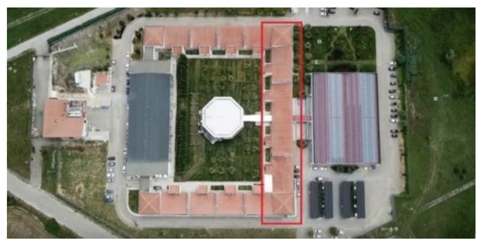
Figure 8.
Interior of the building with view of the reinforced concrete beam.
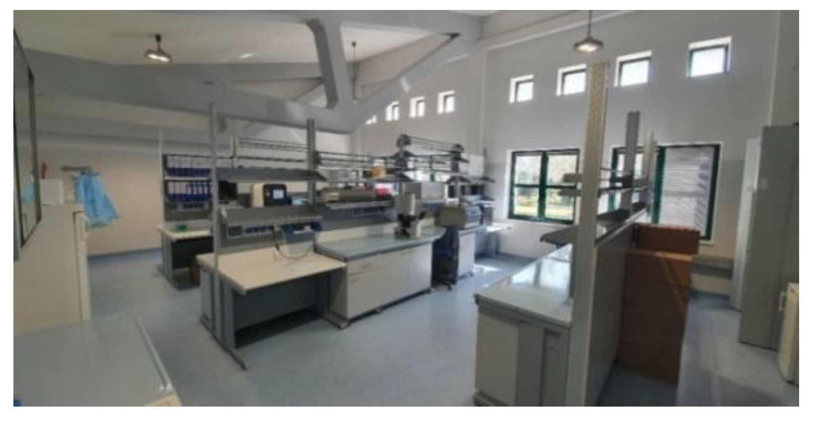
From a structural point of view, the building is made with a load-bearing structure entirely in reinforced concrete, foundations on piles, a floor slab in “predalles” and completion casting on site, a roof made with prefabricated beams in pre-stressed reinforced concrete, with an inverted truss, creating a roof with a single pitch inclined towards the inside of the courtyard. Likewise, with a single pitch inclined towards the inside, the roofing of the waiting mesh modules is made, with a sloped floor slab in “predalles”. Above the roofs, a covering was made with a layer of vapor barrier (3 mm), insulation (6 mm), sheathing (3 mm) and traditional tiles. The external infill walls are made with a masonry in honeycomb blocks; pillars, base and crowning will be slightly protruding, defining slightly recessed square fields. The external façade will be defined by regular square openings of approximately 1.60 m on each side at a height of approximately 1.60 m from the ground. At a height of 53 cm from the upper edge of the frame there will be a pair of square holes of 53 cm on each side, 53 cm apart. All the holes will be closed by thermally broken aluminum frames, with double glazing. The external side elevations are closed by the full heads of the service modules along whose walls only the smaller holes (53 X 53 cm) continue on the upper part of the elevation.
Figure 9.
External side of the laboratory building
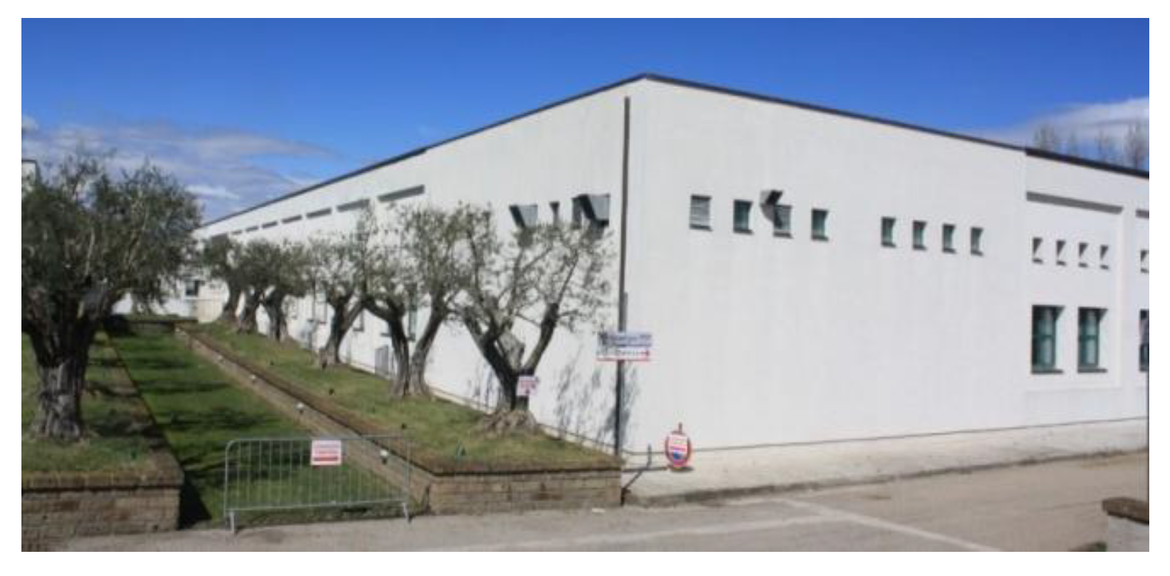
Figure 10.
Interior of the laboratory building services
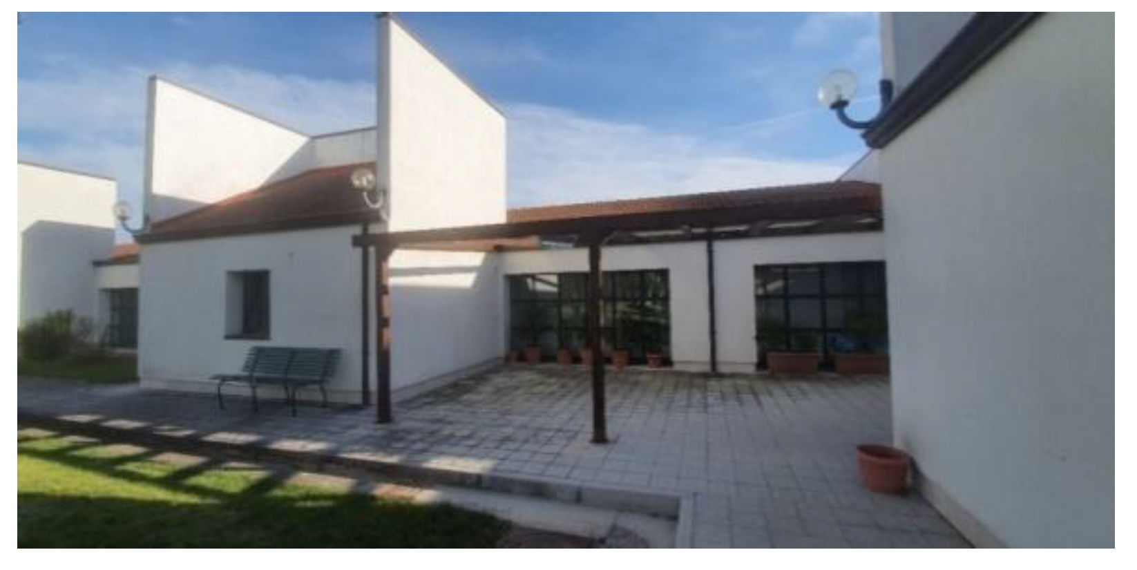
The internal elevation is marked by the protruding volumes of the waiting meshes that are characterized by a central square hole and by the copper drainpipes embedded in the masonry but exposed. Between the two protruding volumes the elevation is defined by two large windows symmetrical with respect to the central axis marked by square modules (6 x 3 modules) of about 60 cm on each side. All the fixtures that characterize the internal elevation will also be in thermally broken aluminum with double glazing. Another defining element of the internal courtyard is constituted by the smoke walls that define the modular scansion of the laboratories and serve to make the functional need for the exit of chimneys on the roofs an architectural “theme”, linked above all to the presence, inside the laboratories, of the chemical hoods. These walls are placed in correspondence with the internal wet walls and are plastered in white. Each laboratory unit has internal walls made of plasterboard panels plastered with epoxy resins: the wall towards the corridor and the dividing wall between the two units is made of two panels with a cavity for the passage of systems. The laboratory floor is in light blue linoleum and has been made to run on the vertical wall for about 20 cm. The doors towards the corridor are in polyurethane covered in polyester, while the internal doors are only in polyester. The corner and head blocks have a special roofing, with a central plan, in metal carpentry with lattice beams and an overlapping structure in IPE profiles: the same roofing package used for the return of the building was installed above. Inside, the same technologies described for the laboratories were used (linoleum, block walls, etc.) with the exception of the radioactive deposits for which a special wall in barium sulphate was created and then covered in linoleum. Between the steel roof and the rooms below, an accessible intermediate floor has been created in the corner blocks where the refrigeration machines needed to operate the equipment below are located. Special types of doors, made of galvanized steel, have also been used for these particular rooms. The layout of the building in repetitive modules requires that the rooms be considered independent from each other, so that the operating hours are completely independent; this choice penalizes the initial installation costs, but it responds to the operational needs of the structure. The air conditioning system in the laboratories is of the all-air type, with heat recovery from the expelled air. Each module is therefore equipped with its own air treatment unit, installed in the system tunnel just below the relevant room; each unit includes a filtering section, the return fan, the heat recovery unit,a hot battery, a cold battery, humidification (if necessary), the supply fan.
As for the supply of electricity, the building is partly powered by the photovoltaic system that serves the entire research center.
Figure 11.
Top view of the Biogem research center.
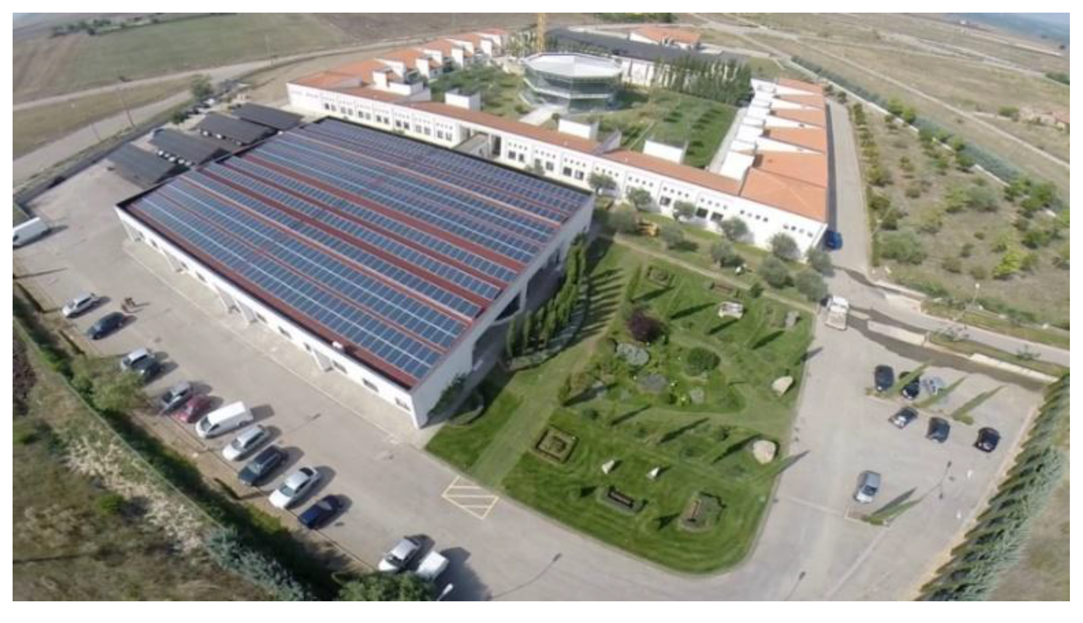
The fire detection system is of the interactive type with individual addressing with ring field detector connection circuits; it has been sized in compliance with the requirements of the UNI 9795, UNI-EN 54 Standards. The system is controlled by a building control unit to which smoke detectors and manual buttons are connected. In the event of an alarm, the control unit will activate optical and acoustic signs, located inside the laboratories and along the corridors, to warn the personnel present of the danger; furthermore, it will start the emergency procedures envisaged, such as stopping the air conditioning systems in the area affected by the fire, disconnecting electrical loads, remote signalling for the intervention of rescue teams, opening the CO2 solenoid valves, activating any automatic extinguishing systems, unlocking the doors of rooms with limited access.
4.3. Applying the Model to Case Studies
4.3.1. Application of the Model According to the CAM Areas (Table 7)
Based on the technological and construction characteristics of the selected case studies, the CAM model was applied for the “Building” and “Building Components” areas, analyzing the indicator entries and multiplying the average of the relative weights by the appropriate satisfaction coefficients. In this way, the score for each indicator is calculated and finally, by adding all the scores, the score for the building under study is obtained.
4.3.2. Application of the Model Based on the Life Cycle Phases of Buildings (Table 8)
Similarly. The case studies were applied to the model relating to the life cycle phases, analyzing the indicator entries and multiplying the relative weight by the appropriate satisfaction coefficients. In this way, the score relating to each indicator is calculated for each life cycle phase and finally, by adding all the scores, the score relating to the building under study is obtained for each life cycle phase.
This section may be divided by subheadings. It should provide a concise and precise description of the experimental results, their interpretation, as well as the experimental conclusions that can be drawn.
5. Results and Discussion
From the application of the models it emerges that the Multipurpose Building exceeds the limit threshold in both models reaching resilience class 2 (scores between 60 and 69), while the Laboratory Building presents a score lower than the threshold.
Table 7.
Summary table of the results of the Multipurpose Building.
| Multipurpose Building | CAM Model | BLC Model | ||||
|---|---|---|---|---|---|---|
| Building System | Production Phase A1-A3 |
Construction Phase A4-A5 |
Exercise Phase B1-B7 |
End of life phase C1-C4 |
Benefits beyond the system D |
|
| Building Components System | ||||||
| Indicators Summary | 65.88 | 60.38 | 62.05 | 59.55 | 62.57 | 59.51 |
| Resilience Factor | 66 | 60 | 62 | 60 | 63 | 60 |
Table 8.
Summary table of the results of the Laboratory Building.
| Laboratory Building | CAM Model | BLC Model | ||||
|---|---|---|---|---|---|---|
| Building System | Production Phase A1-A3 |
Construction Phase A4-A5 |
Exercise Phase B1-B7 |
End of life phase C1-C4 |
Benefits beyond the system D |
|
| Building Components System | ||||||
| Indicators Summary | 39.92 | 36,18 | 39,32 | 38.64 | 39.68 | 34.82 |
| Resilience Factor | 40 | 36 | 39 | 39 | 40 | 35 |
The results show that, with reference to the five resilience thresholds defined by the graph in figure 3, the first case study (multifunctional building) is placed in band 2, while the second case study (laboratory building) does not exceed the threshold of the minimum band.
It is therefore appropriate to intervene through actions that involve the improvement of the critical parameters, in order to obtain an improvement in the resilience class achieved, downstream of the application of the model to the actual state of the buildings.
In order to further analyse the results obtained, the indicators that, in the application of the model to the two case studies, showed greater dissonances were taken into consideration and were divided into two categories (Table 9):
Intrinsic characteristics regarding the construction and technological system
Extrinsic characteristics regarding the relationship between the building and the environment
These indicators are among those that have contributed substantially to the determination of the score and it is no coincidence that most of these indicators refer to specific CAM techniques regarding:
-reduction of the impact on the microclimate and air pollution;
-internal environmental quality;
-maintenance plan of the work;
-end of life.
6. Conclusions
The research is a first step towards the development of a qualitative-quantitative evaluation method for the determination of the resilience factor of buildings.
The methodology was developed through a holistic approach, which involves the integration of different levels of indicators: those characterizing sustainability to the objectives of the 2030 Agenda, up to indicators of an applicative/implementation type, consistent with the technical specifications of the CAM and the relative impact on the phases of the life cycle of buildings. The models developed, in support of the methodology, can be used both in the ante-operam and post-operam phases. In the first case, the attribution of different weights to the various indicators defines the design guidelines, or directs the operators in the sector towards the adoption of strategies that can have the greatest impact towards achieving the initial objective (maximum resilience factor). In the post-operam phase, however, the models allow the resilience factor to be assessed as it stands, simultaneously highlighting the particular critical issues, and directing the operators towards possible improvement strategies.
The results obtained highlight the main design guidelines:
A- Guidelines for the construction and technological system
- Modular construction system
- Opportunity for disassembly and selective demolition
- Use of materials with EPD certification
- Morphological and formal characteristics that give aerodynamics to the work
- Presence of external vertical connections
- Structural monitoring systems
B- Guidelines on the relationship between the building and the environment
- Predictive and scheduled maintenance plan for the work
- Sun protection devices
- Natural ventilation systems
- Highly reflective opaque external closures (for roofing and casings)
- Low-emissivity transparent external closures
The guidelines indicated highlight the particular predisposition of dry construction systems towards the objective of resilient design. The use of prefabricated and semi-prefabricated building components, produced off-site, allows for optimization in the organization and logistics of the construction site, reducing waste of raw materials as well as all those interference risks that may arise from on-site work, i.e. production of dust, noise, vibrations, etc.
The construction sites are cleaner and the organization of the assembly of the structure significantly reduces the work on site and with it also the risks related to safety at work. Through this type of construction, disassembly is allowed in the end-of-life phase, allowing the greatest amount of material recovery for future reuse.
The technological characteristics of a dry system allow for greater ease of monitoring/maintenance of the architectural elements, making it more flexible also with respect to any regulatory adjustments regarding energy efficiency.
The work could provide a first step towards the development of a regulatory framework aimed at the elaboration of a resilience protocol. This protocol could be used as a guideline for the determination of resilience and sustainability objectives and as a method of comparability between buildings.
Furthermore, in the context of public procurement, the assessment of resilience could be considered a further sustainability parameter that can determine the attribution of rewarding scores during the awarding of the contract.
The research implementation prospects will concern:
1) the identification of possible improvement actions, selected on the basis of critical parameters, in order to achieve an improvement in the resilience class;
2) the estimate of direct costs related to the improvement actions referred to in the previous point. This would allow us to highlight the economic convenience of possible improvement actions, thus outlining the most virtuous cost/benefit profile.
Author Contributions
Conceptualization, G.D.R. and M.R.L.; methodology, G.D.R., M.R.L. and A.L.; software, M.R.L. and A.L.; validation, G.D.R.; formal analysis, M.R.L. and A.L.; investigation, M.R.L. and A.L.; resources, G.D.R.; data curation, G.D.R. and M.R.L.; writing—original draft preparation, M.R.L.; writing—review and editing, G.D.R. and A.L.; visualization, G.D.R. and M.R.L.; supervision, G.D.R.; project administration, G.D.R.; funding acquisition, G.D.R. All authors have read and agreed to the published version of the manuscript.
Funding
This research received no external funding.
Institutional Review Board Statement
Not applicable.
Informed Consent Statement
Not applicable.
Data Availability Statement
Not applicable.
Acknowledgments
Not applicable.
Conflicts of Interest
The authors declare no conflicts of interest.
Abbreviations
The following abbreviations are used in this manuscript:
| CAM | Criteri Ambientali Minimi italiani (Minimum Environmental Criteria) |
| LCA | Life Cycle Assessment |
| BLC | Building Life Cycle |
| EPD | Environmental Product Declaration |
References
- Dand Wilde, P., Coley, D. Editorial, Implications of a changing climate for buildings. Building and Environment, Vol.56. 2012.
- Lacasse MA; Gaur A.; Moore TV Durability and Climate Change—Implications for Service Life Prediction and the Maintainability of Buildings. Buildings 2020, 10(3), 53; [CrossRef]
- Mussi, G. “Resilient and sustainable architecture” The portal for construction and architecture Infobuild 2019 Source: https://www.infobuild.it/approfondimenti/architettura-resiliente-sostenibile-progettazione-urbana/.
- Mussi, G. “Five choices for a more sustainable construction” The portal for construction and architecture Infobuild 2020 Source: https://www.infobuild.it/approfondimenti/5-scelte-per-edilizia-sostenibile/.
- Saifudeen, A.; Mani , M. Adaptation of buildings to climate change: an overview, 16 Feb 2024 - Frontiers in Built Environment. [CrossRef]
- Kulsum, F. Sustainable and Resilient Architecture: Prioritizing Climate Change Adaptation, Civil Engineering and Architecture 12(1): 577-585. [CrossRef]
- Wu, D. Towards Resilient Urban Design: Revealing the Impacts of Built Environment on Physical Activity Amidst Climate Change. Buildings 2025, 15(19), 3470;. [CrossRef]
- Pallubinsky, H.; Kramer, R.P. & van Marken Lichtenbelt, W.D. Establishing resilience in times of climate change—a perspective on humans and buildings. Climatic Change 176, 135 (2023). [CrossRef]
- Ljubomir, J. Designing Resilience of the Built Environment to Extreme Weather Events, Sustainability 2018, 10(1), 141;. [CrossRef]
- Katunský, D.; Kabošová, L.; Dolníková, E.; Zozulák, M. Research of building structures in extreme climate conditions. Journal of Civil Engineering. Volume 14 (2019): Issue 2 (December 2019). [CrossRef]
- Pastori, S. and Mazzucchelli, E.S. Climate Change and Extreme Wind Events: Overview and Perspectives for a Resilient Built Environment, IntechOpen 01 June 2023. [CrossRef]
- Blandon, B.; Palmero, L.; Di Ruocco, G. The Revaluation of Uninhabited Popular Heritage under Environmental and Sus-tainability Parameters. Sustainability 2020, 12(14), 5629;. [CrossRef]
- Popowicz, M., Katzer, N.J., Kettele, M. et al. Digital technologies for life cycle assessment: a review and integrated combination framework. Int J Life Cycle Assess 30, 405–428 (2025). [CrossRef]
- Lima, S.; Duarte. S.; Exenberger, H.; Fröch, G.; Flora, M. Integrating BIM-LCA to Enhance Sustainability Assessments of Constructions. Sustainability 2024, 16(3), 1172;. [CrossRef]
- Bruno, A.; Menichini. T.; Silversti, L. Life Cycle Sustainability Assessment (LCSA): A comprehensive overview of existing integrated approaches to LCA, S-LCA, and LCC. European Journal of Sustainable Development. Vol. 14 No. 3 (2025). [CrossRef]
- Cerchione, R.; Morelli, M.; Passaro, R.; Quinto, I. A critical analysis of the integration of life cycle methods and quantitative methods for sustainability assessment. Corporate Social Responsibility and Environmental Management. Volume 32, Issue 2. October 2024. [CrossRef]
- Bani, K.; Despoina, D.; Avgoustaki, D.; Bartzanas, T. Integrating life cycle assessment into green infrastructure: a systematic review and meta-analysis of urban sustainability strategies. Front. Sustain. Cities, 18 June 2025. Sec. Urban Greening. Volume 7 – 2025. [CrossRef]
- Backes, J.G.; Steinberg, L.S.; Weniger, A.; Traverso, M. Visualization and Interpretation of Life Cycle Sustainability Assessment—Existing Tools and Future Development. Sustainability 2023, 15(13), 10658; [CrossRef]
- Moutik, B.; Summerscales, J.; Graham-Jones, J.; Pemberton, R. Life Cycle Assessment Research Trends and Implications: A Bibliometric Analysis. Sustainability 2023, 15(18), 13408. [CrossRef]
- Rao, P.A.; Rahman, M.M.; Duraman, S.B. Adopting circular economy in construction: a review. Front. Built Environ., 20 January 2025. Volume 11 – 2025. [CrossRef]
- Gasparri, E.; Arasteh, S.; Stracchi, P.; Brambilla, A. Circular economy in construction: A systematic review of knowledge gaps towards a novel research framework. Front. Built Environ., 19 July 2023. Volume 9 – 2023. [CrossRef]
- Krajewska, A.; Siewczyńska, M. Circular Economy in the Construction Sector in Materials, Processes, and Case Studies: Research Review. Sustainability 2025, 17(15), 7029. [CrossRef]
- Idir, R.; Djerbi, A.; Tazi, N. Optimising the Circular Economy for Construction and Demolition Waste Management in Europe: Best Practices, Innovations and Regulatory Avenues. Sustainability 2025, 17(8), 3586. [CrossRef]
- Firoozi, A.A.; Firoozi, A.A. Circular Economy for Sustainable Construction Material Management. Journal of Civil Engineering and Urbanism. Volume 12, Issue 4: 70-81; December 2025. [CrossRef]
- Jayakodi, S.; Senaratne, S.; Perera, S. Circular Economy Business Model in the Construction Industry: A Systematic Review. Buildings 2024, 14(2), 379. [CrossRef]
- Otasowie, O.; Aigbavboa, C.; Oke, A.E.; Adekunle, P. Circular economy business model: an exploratory study on the key resources for construction organisations. Built Environment Project and Asset Management 1–18. [CrossRef]
- Keles, C.; Rios, F.C.; Hoque, S. Digital Technologies and Circular Economy in the Construction Sector: A Review of Lifecycle Applications, Integrations, Potential, and Limitations. Buildings 2025, 15(4), 553. [CrossRef]
- Rodrigo, N.; Omrany, H.; Chang, R.; Zuo, J. Leveraging digital technologies for circular economy in construction industry: a way forward. Smart and Sustainable Built Environment, vol. 13, issue 1, pp. 85-116. [CrossRef]
- Ibe, C.N.; Serbescu, A.; Hossain, M.; Ibe, I.I. Optimizing circular economy practices in construction: a systematic review of material management strategies. Built Environment Project and Asset Management. 15 (5), pp. 1020-1035. [CrossRef]
- Wieser, A.A.; Scherz, M.; Passer, A.; Kreiner, H. Challenges of a Healthy Built Environment: Air Pollution in Construction Industry. Sustainability 2021, 13(18), 10469;. [CrossRef]
- Wang, G.; Luo, T.; Luo, H. et al. A comprehensive review of building lifecycle carbon emissions and reduction approaches. City Built Enviro 2, 12 (2024). [CrossRef]
- Zhao, Q.; Wu, Z.; Yu, Z.; Wang, T.; Huang, S. Exploring Carbon Emissions in the Construction Industry: A Review of Accounting Scales, Boundaries, Trends, and Gaps. Buildings 2025, 15(11), 1900. [CrossRef]
- Building Materials And The Climate: Constructing A New Future, 12 September 2023 (UNEP, 2023). Available on: https://www.unep.org/resources/report/building-materials-and-climate-constructing-new-future.
- Aparna, K.; Baskar, K. Scientometric analysis and panoramic review on life cycle assessment in the construction industry, in Innovative Infrastructure Solutions, Volume 9, Issue 4, article id.96, April 2024. [CrossRef]
- Rathnasinghe, A.P.; Thurairajah, N.; Jones, P.; Goulding, J. The critique of sustainability discourse within the off-site construction (OSC): a systematic-scientometric review, in Architectural Engineering and Design Management. [CrossRef]
- Olayiwola, K.; Perera, S.; Kagioglou, M.; Jin, X.; Sharafi, P. A PESTEL Analysis of Problems Associated with the Adoption of Offsite Construction: A Systematic Literature Review. Buildings 2025, 15(13), 2146. [CrossRef]
- Wang, M.; Wang, C.C.; Sepasgozar, S.; Zlatanova, S. A Systematic Review of Digital Technology Adoption in Off-Site Construction: Current Status and Future Direction towards Industry 4.0. Buildings 2020, 10(11), 204. [CrossRef]
- Najafzadeh, M.; Yeganeh, A. AI-Driven Digital Twins in Industrialized Offsite Construction: A Systematic Review. Buildings 2025, 15(17), 2997. [CrossRef]
- Di Ruocco, G.; Melella, R. Evaluation of environmental sustainability threshold of “humid” and “dry” building systems, for reduction of embodied carbon (CO2). VITRUVIO - International Journal of Architectural Technology and Sustainability. [CrossRef]
- Sicignano, E.; Di Ruocco, G.; Melella, R. Mitigation Strategies for Reduction of Embodied Energy and Carbon, in the Construction Systems of Contemporary Quality Architecture. Sustainability 2019, 11(14), 3806;. [CrossRef]
- Broadhead, J. P.; Daniel E. I.; Oshodi, O.; Ahmed, S. (2023). Exploring offsite construction for the construction sector: a literature review. Proceedings of the 31st Annual Conference of the International Group for Lean Construction (IGLC31), 735–745. Modular & Offsite Construction 735. [CrossRef]
- Manouchehri, B.; Han, S.: Nasiri, F. Performance Evaluation Model to Enhance Life Cycle Productivity in Modular and Off-Site Construction: A Process-Oriented Approach, in 2025 Proceedings of the 42nd ISARC, Montreal, Canada, pp. 556-563. [CrossRef]
- Jang, J.; Ahn, S.; Cha, S.H.; Cho, K.; Koo, C.; Kim, T.W. Toward productivity in future construction: mapping knowledge and finding insights for achieving successful offsite construction projects Open Access, in Journal of Computational Design and Engineering, Volume 8, Issue 1, February 2021, pp. 1–14. [CrossRef]
- Cheng, Z.; Tang, S.; Liu, H.; Lei, Z. Digital Technologies in Offsite and Prefabricated Construction: Theories and Applications. Buildings 2023, 13(1), 163. [CrossRef]
- Tan, T.; Mills, G.; Papadonikolaki, E.; Li, B.; Huang, J. Digital-enabled Design for Manufacture and Assembly (DfMA) in offsite construction: A modularity perspective for the product and process integration, in Architectural Engineering and Design Management, Volume 19, 2023 - Issue 3, pp. 267-282. [CrossRef]
- Parracho, D. et al. Modular Construction in the Digital Age: A Systematic Review on Smart and Sustainable Innovations. Buildings 2025, 15(5), 765. [CrossRef]
- Saifudeen, A.; Mani, M. Adaptation of buildings to climate change: an overview, in Front. Built Environ., 16 February 2024. Sec. Sustainable Design and Construction, Volume 10 – 2024. [CrossRef]
- Tajuddeen, I.; Sajjadian, S.M. Climate change and the built environment - a systematic review. Environ Dev Sustain (2024). [CrossRef]
- EU-LEVEL TECHNICAL GUIDANCE ON ADAPTING BUILDINGS TO CLIMATE CHANGE. Available on: https://op.europa.eu/en/publication-detail/-/publication/7cca7ab9-cc5e-11ed-a05c-01aa75ed71a1/language-en.
- Bouramdane, A-A. Shaping resilient buildings and cities: Climate change impacts, metrics, and strategies for mitigation and adaptation. College of Engineering and Architecture, International University of Rabat (IUR), IUR Campus, Technopolis Park, Rocade Rabat-Salé, Sala Al Jadida 11103, Morocco. [CrossRef]
- Wang, X.; Ramakrishnan, S. Resilience and Adaptation in Buildings. In: Environmental Sustainability in Building Design and Construction. Springer, Cham, 2021. [CrossRef]
- Chamindi Malalgoda et al. Climate Change Adaptation in the Built Environment. Transdisciplinary and Innovative Learning, 2025. Available on: https://link.springer.com/book/10.1007/978-3-031-75826-3.
- Agency 2030 for Sustainable Development - Agency for Territorial Cohesion. Website:https://www.agenziacoesione.gov.it/comunicazione/agenda-2030-per-lo-sviluppo-sostenibile/.
- Moncaster, A.; Symons, K. A method and tool for 'cradle to grave' embodied energy and carbon impacts of UK buildings in compliance with the new TC350 standards. Energy and Buildings 66(11):514–523. 2013.
- Ministero dell'Ambiente e della Sicurezza Energetica. Sostenibilità dei prodotti e dei consumi - CAM e Certificazioni. Available on : https://gpp.mase.gov.it/sites/default/files/2024-08/allegato-tecnico-CAM-edilizia-07-06-2022-rev-correttivo.pdf.
- Cellura, T.; Cellura, L. The new manual of Minimum Environmental Criteria in Construction, Maggioli Editore. Italy, 2018.
Figure 1.
UNI EN 15978:2011: Life Cycle Assessment of Buildings
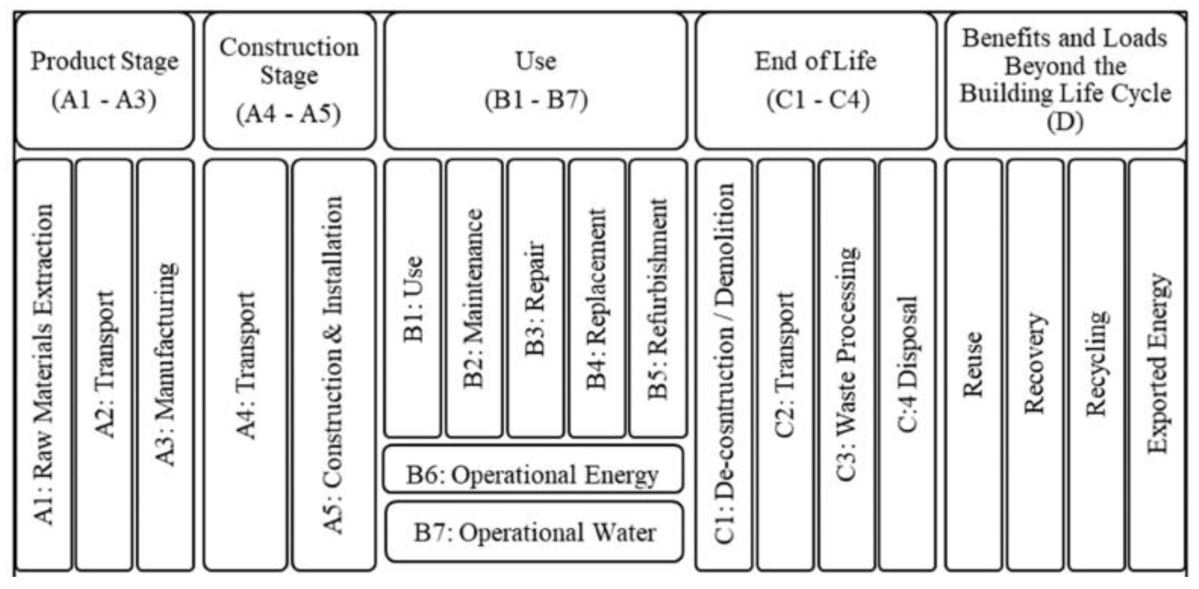
Figure 3.
Resilience thresholds
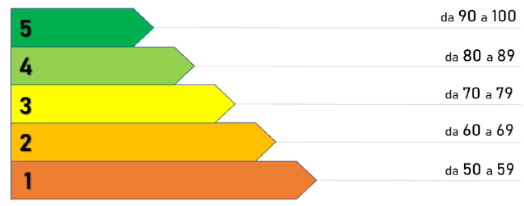
Figure 4.
Top view of the Biogem research center
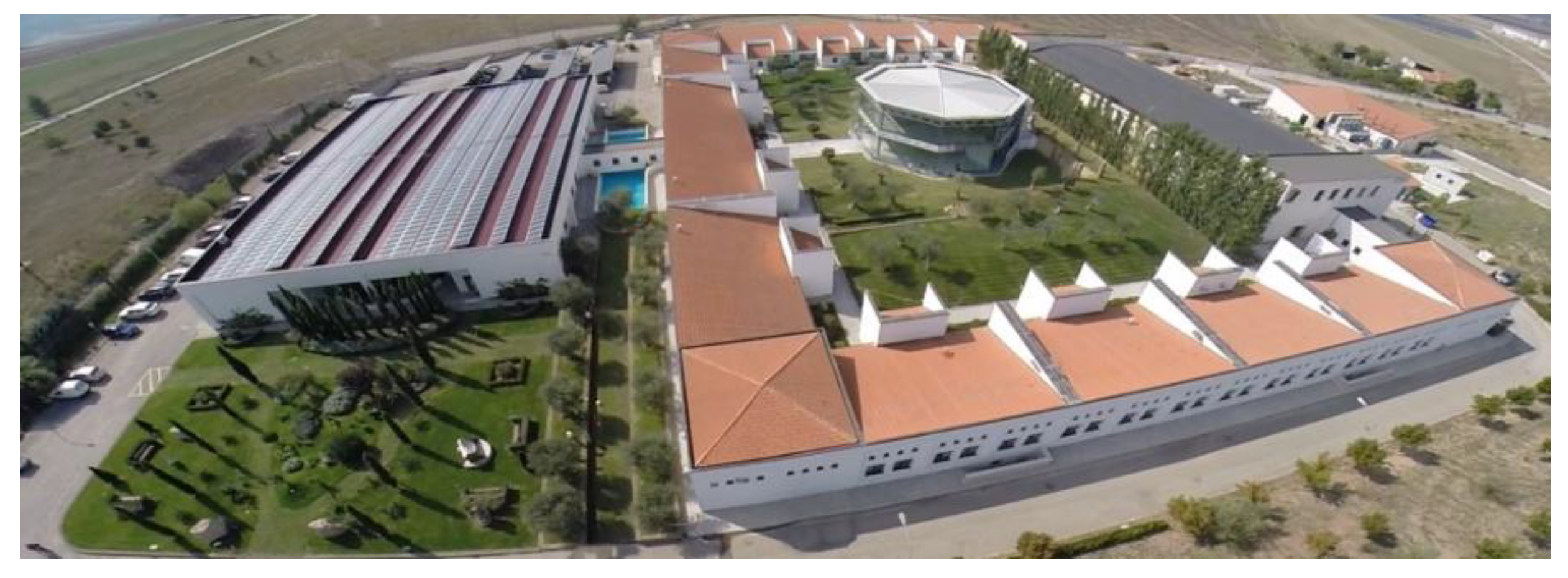
Figure 5.
Identification of multifunctional building.
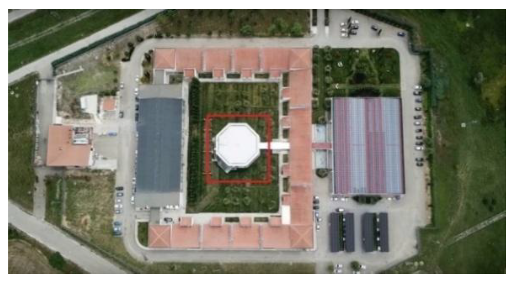
Figure 6.
Multipurpose Building
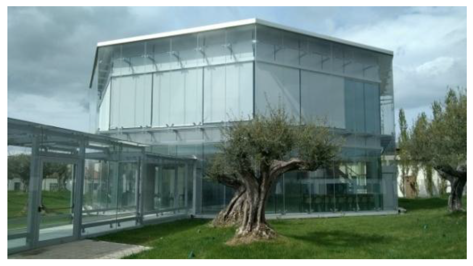
Table 6.
Definition of the indicator satisfaction coefficient
| Satisfaction Coefficient | Assessment |
|---|---|
| 0 | Nothing |
| 0.33 | Rare |
| 0.66 | Good |
| 1.00 | Optimal |
Table 9.
Indicators with the greatest contribution in determining the score.
| Intrinsic characteristics regarding the construction and technological system | Multipurpose Building | Laboratory Building |
|---|---|---|
| Modular elevation structures | 1 | 0.33 |
| Disassembly and selective demolition | 1 | 0 |
| Materials with DAP/EPD certification (Environmental Product Declaration) [UNI EN 15804 and ISO 14025] | 1 | 0 |
| Elevation structures for aerodynamic design | 1 | 0 |
| External vertical connections (fire escapes) | 1 | 0 |
| Structural monitoring systems | 1 | 0 |
| Intrinsic characteristics regarding the relationship between the building and the environment | Multipurpose Building | Laboratory Building |
| Predictive and scheduled maintenance plan of the work | 1 | 0 |
| Sun protection devices | 1 | 0 |
| Natural ventilation systems | 1 | 0 |
| Highly reflective opaque external closures (for roofing and casings) | 1 | 0 |
| Low-emissivity transparent external closures | 1 | 0 |
| Lean Construction | 1 | 0 |
Disclaimer/Publisher’s Note: The statements, opinions and data contained in all publications are solely those of the individual author(s) and contributor(s) and not of MDPI and/or the editor(s). MDPI and/or the editor(s) disclaim responsibility for any injury to people or property resulting from any ideas, methods, instructions or products referred to in the content. |
© 2025 by the authors. Licensee MDPI, Basel, Switzerland. This article is an open access article distributed under the terms and conditions of the Creative Commons Attribution (CC BY) license (http://creativecommons.org/licenses/by/4.0/).
Copyright: This open access article is published under a Creative Commons CC BY 4.0 license, which permit the free download, distribution, and reuse, provided that the author and preprint are cited in any reuse.


