
Submitted:
25 November 2025
Posted:
26 November 2025
You are already at the latest version
Abstract
Connecting distributed applications across multiple cloud-native domains is growing in complexity. Applications have become containerized and fragmented across heterogeneous infrastructures, such as public clouds, edge nodes and private data centers, including emerging IoT-driven environments. Existing networking solutions like CNI plugins and service meshes have proven insufficient for providing isolated, low-latency and secure multi-cluster communication. By combining SDN control with Kubernetes abstractions, we present L2S-CES, a Kubernetes-native solution for multi-cluster layer-2 network slicing that offers flexible isolated connectivity for microservices while maintaining performance and automation. In this work, we detail the design and implementation of L2S-CES, outlining its architecture and operational workflow. We experimentally validate against state-of-the-art alternatives, and show superior isolation, reduced setup time, native support for broadcast and multicast, and minimal performance overhead. By addressing the current lack of native link-layer networking capabilities across multiple Kubernetes domains, L2S-CES provides a unified and practical foundation for deploying scalable, multi-tenant, and latency-sensitive cloud-native applications.
Keywords:
cloud-native
; software-defined networking
; slicing
; edge-cloud integration
1. Introduction
From submarine cables laid across the ocean floor to satellite-based communication systems, the infrastructure underlying global Internet data flows is diverse and complex. As millions of users rely on these networks daily, the Internet faces increasing demands and intricate technical challenges, including network interoperability, routing within highly dynamic topologies, and ensuring security and resilience across administrative domains [1].
These challenges are largely addressed by virtualization, a technology that allows the partitioning of physical resources into multiple independent virtual environments [2,3]. More precisely, in data center communications, by abstracting hardware components, virtualization allows them to manage computing and networking resources more efficiently. It enables multiple users to share the same physical infrastructure while maintaining secure, isolated, and customizable environments.
Building on these virtualization paradigms, containerization is one technique that enables deploying applications in lightweight isolated computing environments, known as containers [4]. Modern software applications are increasingly decomposed into multiple containers [5] given that microservice architectures enable teams to be more productive, and improve the scalability and maintainability of services [6]. Those are reliant on cloud-native platforms, as the elasticity and on-demand provisioning eases its implementation, so containerized microservices need automated management through orchestration. Container orchestration platforms, such as Kubernetes [7], have evolved well beyond their initial purpose, supporting diverse workloads and operational paradigms [8], while its networking subsystem, in particular, remains comparatively constrained. The abstractions that once sufficed for container orchestration now face limitations in scalability, flexibility and integration with emerging network paradigms. Pods, which encapsulate containers, are the smallest units of computation in Kubernetes, and lack network isolation between one another. Additionally, when exposing a pod to the Internet, tools for securing them rely on the application implementation, which leaves room for errors.
Network isolation can be achieved with layer-2 mechanisms using software defined networking (SDN) and network functions virtualization (NFV). SDN logically separates the control and data planes, exposing open southbound interfaces that allow operators to program forwarding behavior at run time [9]. Complementarily, NFV relocates packet-processing functions—firewalls, load balancers, virtual switches—onto commodity servers, decoupling them from proprietary middleboxes [10]. NFV therefore offers the elastic scaling and rapid instantiation needed when Kubernetes clusters burst or shrink. Combining SDN’s holistic visibility with NFV’s agile function placement yields a modular toolkit that (i) enforces network isolation end-to-end, (ii) minimizes hardware lock-in, and (iii) shortens service-deployment cycles from weeks to seconds—all of which are indispensable for layer-2 virtual networks setup.
Building on the capabilities of SDN and NFV, network slicing is the solution that enables the provision of service instances, network functions, and the necessary resources—aligned with the specific requirements of those services—within logically isolated segments of a shared infrastructure [11]. A slice is defined as the set of network functions, and the resources to run these network functions, providing a logical infrastructure suited to the user’s needs. Each slice can be tailored to optimize characteristics such as bandwidth, latency, security, or reliability, effectively ensuring that different workloads and tenants can coexist without negatively impacting each other. The fine-grained control granted by SDN is essential for network slicing, as each slice may demand distinct forwarding policies, quality of service (QoS) profiles, or traffic-engineering objectives that can change on short notice.
In this context, the primary goal of this paper is to provide a homogeneous platform that facilitates the creation of network slices which provision isolated communication, and make it scalable and adaptable to current edge-cloud solutions, as depicted in Figure 1. By creating a multi-domain slice spanning multiple Kubernetes clusters, multiple virtual networks are formed, interconnecting containerized microservices across these clusters. This approach not only ensures isolated and secure communication channels but also facilitates observability and metrics gathering. As a result, operators gain visibility into network performance, allowing them to monitor resource usage, detect anomalies, and more effectively manage network policies.
This paper continues some research that has been done on layer-2 networking solutions for cloud native environments, like L2S-M [12] and the Inter-Domain Connectivity Controller (IDCO) [13]. Our approach integrates concepts from both solutions, and extends them by providing connectivity across multiple Kubernetes clusters and introducing a user-friendly API that integrates with Kubernetes. The end result is Link Layer Secure ConnEctivity slicES for microservices platforms (L2S-CES), a network slicing solution that by connecting multiple cloud native domains, tackles key challenges in deploying edge cloud solutions, such as securing service exposure, expanding business opportunities, and managing data flow complexity.
This solution is evaluated and validated within a real-world architecture using a practical use-case scenario, and we demonstrate its capabilities, by highlighting the benefits of incorporating network slicing into multi-tenant Kubernetes environments, and by showcasing its potential for broad applicability. All code and artifacts used in this paper—including those required to reproduce the validation results, the proposed scenario, documentation, and setup scripts—are available in our official GitHub repository [14].
The rest of this paper is structured as follows. Section 2 presents the foundational concepts and technologies that underpin the proposed approach. Section 3 details the design architecture, followed by Section 4, which details the technologies and tools utilized in the solution. Section 5 reports on the validation results and evaluates the effectiveness of the proposed method. Finally, Section 6 summarizes the main conclusions and outlines potential directions for future research.
2. Related Work
Connecting application workloads across diverse cloud and edge environments has been addressed through various methods, each with distinct limitations and advantages. This section provides an overview of existing solutions, introducing network slicing techniques used in infrastructure-as-a-service (IaaS) projects, and then focusing on how slicing and inter-cluster connectivity is currently being done in cloud-native platforms, such as Kubernetes, concluding with a comparison table of main functionalities that may be expected in a network slicing solution.
2.1. Cloud Platform Solutions for Network Slicing Orchestration
Cloud platforms incorporate slicing through varied network-provisioning techniques that enable isolation, segmentation, and resource allocation in the provided network. Many of these solutions are based on SDN, because of the flexibility these architectures offer, while NFV uses virtualization to replace specialized hardware appliances with software-based network functions, improving flexibility and scalability.
As explained earlier, SDN is a network architecture that separates the control plane from the data plane, enabling more flexible and dynamic network management. Rather than configuring devices like routers and switches individually, SDN centralizes network logic into a dedicated controller, streamlining configuration and policy enforcement. This approach is commonly implemented using protocols such as OpenFlow [15].
NFV virtualizes network functions, replacing specialized hardware with software-based applications. This reduces reliance on proprietary equipment, improving network scalability, flexibility, and efficiency.
A notable example of the practical integration of SDN and NFV technologies is Open Source MANO (OSM) [16], an open-source implementation aligned closely with the ETSI NFV Management and Orchestration (MANO) framework. OSM primarily focuses on providing a robust orchestration platform for virtual network functions (VNFs), effectively managing life-cycle operations including instantiation, scaling, and termination of VNFs. By adhering closely to the ETSI NFV architectural framework, OSM ensures compatibility and streamlined integration within multi-vendor cloud and edge deployments, enhancing the flexibility and scalability of network slicing solutions.
A widely used VIM with which OSM integrates is OpenStack [17]. As an open-source cloud operating system, OpenStack provides IaaS by managing computing, storage, and networking resources through well-defined, standardized APIs. An essential element within the OpenStack architecture is the support for SDN and NFV, facilitating highly flexible and dynamic network slicing capabilities. Particularly, OpenStack employs components such as Neutron, a networking project within OpenStack that provides network connectivity as a service between interface devices managed by other OpenStack services. Neutron integrates closely with Open vSwitch (OvS), a multilayer software switch that can act as an SDN-managed virtual bridge [18], enabling the creation of virtual isolated networks. This capability is crucial for network slicing, as it provides the necessary isolation, segmentation, and performance management required by modern network workloads.
Amazon Web Services and Google Cloud both offer commercial, managed cloud IaaS solutions, EC2 [19] and Compute Engine [20], respectively. Virtual networking is provisioned in both solutions, relying on SDN to provide functionalities like on-demand virtual private networks and cross-cloud networks.
The cloud provider solutions detailed in this section serve as foundational technologies and methodologies essential for understanding modern network slicing orchestration. By analyzing these platforms, it is shown how combining SDN and NFV principles, isolation, segmentation, and dynamic resource management are achieved in IaaS scenarios. This analysis sets a necessary baseline for appreciating the evolution of network slicing in cloud-native platforms, like Kubernetes.
2.2. Kubernetes Network Virtualization Solutions
The functionality and applicability of Kubernetes [7] has significantly evolved over recent years. Initially, Kubernetes was developed as a cloud platform intended to deploy containerized web applications. Over time, Kubernetes has expanded to support increasingly sophisticated scenarios, including fine-grained access control, complex networking, and deployments involving constrained devices. While basic networking between containers remains straightforward, networking solutions have needed continuous adaptation to support emerging requirements. To address these evolving needs, the container networking interface (CNI) framework [21] was introduced.
2.2.1. CNI Plugins
CNI is a framework utilized by developers to create network plugins in Linux environments. The CNI manages the life-cycle of network interfaces for containers, including interface creation, deletion, and IP address assignment. Kubernetes CNI plugins are implementations of the CNI framework that provide connectivity between pods and communicate those to external networks using Linux kernel utilities. Flannel [22] serves as a representative example of a CNI plugin, implementing VXLAN tunnels among the cluster nodes and network bridges for connecting pods to this VXLAN overlay, providing basic communication and IP address management.
As mentioned in the introduction, Kubernetes’ scope has increasingly expanded to edge cloud solutions, IoT scenarios and multi-tenant solutions. These CNI plugins, in their basic form, are not sufficient for supporting secure inter-cluster communication, observability, and advanced traffic management. Some CNI plugins have introduced extensions that partially address these limitations.
A notable example of this approach is Calico [23], one of the most popular Kubernetes CNI plugins. It provides versatility in network solutions by enabling the administrator to choose which data plane should be used. Calico can optionally establish communication between pods residing on the same host, forwarding packets using eBPF, a technology that enables loading software into the kernel, as programs directly attached to the pods’ virtual interfaces, thereby improving intra-cluster communication efficiency, as it can bypass many of the packet processing layers in the Linux network stack. Calico has addressed multi-cluster connectivity for industry use, with a federated approach, through Tigera’s commercial solution, Calico Enterprise [24]. A multi-cluster mesh is established, with one cluster serving as the service host, responsible for providing endpoints for the pods accessible from all clusters in the mesh. Despite being an open-source project, the cluster-mesh solutions provided by Calico are marketed primarily as enterprise solutions and are not freely available for general public use.
Another emerging CNI plugin that achieves higher throughput and lower latency compared to Calico, is Cilium [25], primarily through a more extensive use of eBPF [26]. Cilium supports multi-cluster networking through ClusterMesh, which deploys a dedicated API server per cluster to manage service discovery and encryption keys, enabling distributed networking. Packet routing is performed using packet headers, or via hybrid routing mode enabling direct pod-to-pod communication.
Other solutions more targeted on security aspects, like Kube-OVN [27], solve the inter-cluster connectivity with its component OVN interconnection (OVN-IC), by creating a single equal cost multiple path (ECMP) tunnel between two clusters with gateways on both sides [28]. While Kube-OVN offers enhanced connectivity and security through IPSec, it currently supports direct connectivity only between two clusters. Extending communication to multiple clusters increases complexity, requiring manual route configuration. Moreover, while traffic is isolated inside the cluster, OVN-IC uses layer-3 routing mechanisms for inter-cluster solutions, meaning that traffic between clusters is not inherently isolated at layer-2, leaving it more susceptible to certain attacks unless additional security measures are applied.
With CNI plugins, certain aspects of network slicing can be supported. Calico and Cilium both advertise the usage of network policies alongside a cluster mesh, allowing multiple pods to connect from one cluster to another. However, it remains limited in scope, particularly to some layer-7 protocols, such as HTTP and HTTPS, and only offers functionality in these specific protocols. Kube-OVN is not able to provide this autonomously, it relies on other networking solutions, such as Submariner [29], which will be further discussed later. While Multus can support multiple interfaces per pod, it does not natively manage inter-cluster connectivity or network slicing. It can serve as a complementary approach when the network administrator has in-depth knowledge and full control over the nodes in each cluster; however, the setup is complex and lacks any form of automation.
As many of these plugins rely on additional abstractions to enforce fine-grained policies and enhance observability, developers and system administrators often adopt service meshes as a complementary solution.
2.2.2. Kubernetes Service Meshes
CNI plugin solutions, such as Calico and Cilium, often rely on service meshes to enforce network policies, enhance security, and provide observability. In addition, there are standalone service mesh solutions developed independently from CNI plugins, offering inter-cluster connectivity for pods. A service mesh is an abstraction layer that defines how pods are connected by using the proxy structural pattern. Traffic is routed through a proxy that impersonates the pod, enforces layer-7 rules, and then forwards the request to the pod. For instance, a service mesh can enforce access control policies by acting as the pod’s proxy and then enforcing rules based on HTTP headers.
Service meshes typically support standardized protocols such as gRPC and HTTP. However, reliance on these protocols can lead to increased latency [30]. Another critical limitation is the absence of strict network isolation since all workloads share the same virtual network. This poses security risks in multi-tenant environments, delegating security responsibilities to the application layer, thereby increasing application complexity.
Regarding network slicing, service meshes can facilitate multi-cluster service discovery. However, as their core focus is not slicing, they typically do not incorporate dedicated operators or controllers capable of dynamically managing network slices. This implies limited granular control of the network, insufficient isolation and limited options when designing network scenarios.
Two prominent service mesh solutions are Istio [31] and Linkerd [32]. Both provide comprehensive documentation and built-in mechanisms for managing application exposure across clusters. They achieve this by sharing service states and configurations across clusters and extending the Kubernetes API into a unified, shared operational domain. Both solutions have ways to provide multi-cluster networking, by writing on the Kubernetes Service API and scaling it to a multi-cluster level. Similarly to how CNI plugins are limited in terms of protocols, these solutions offer limited configuration flexibility.
2.2.3. Evolution of Kubernetes Virtual Networking
Alternative solutions that are designed with a focus on providing more options when doing multi-cluster deployments in Kubernetes are currently under active development. These are designed specifically to facilitate integration with other CNI plugins and interoperate with service meshes as well.
One of these solutions is L2S-M [12]. L2S-M is an open-source solution developed by Universidad Carlos III de Madrid (UC3M) and Telefónica Investigación y Desarrollo (TID), is currently present in multiple european funded projects [12] and it forms the basis of this paper’s design. With capabilities to work alongside other CNI plugins, L2S-M enables the creation of virtual networks that deliver isolated layer-2 communication, providing consistent connectivity between application workloads. Traffic between workloads within the same virtual network is completely isolated from other networks and can be encrypted using standard IPSec technologies. This represents a significant advancement in application security. However, it requires further enhancements in design and implementation before it can be fully recognized as a complete network slicing solution, as it lacks support for dynamic slice creation and management, and lacks automated deployment of multi-cluster virtual networks.
In contrast, as a multi-cluster networking tool for Kubernetes clusters, Kubeslice [33] aims to provide a framework to build slices. It defines a slice by the set of clusters that are associated with one another. It utilizes network service mesh (NSM) technology [34], distinct from traditional service mesh implementations. A network service mesh is an abstraction layer that connects multiple microservices or pods by providing a proxy for each so that their connection can be manipulated with layer-3 and layer-4 mechanisms. The NSM connects two containers forming a vWire, a set of layer-3 rules that enable packets to go from one of the pods to the other as if they were directly connected. Kubeslice uses this by setting up virtual private network (VPN) gateways to secure the communication, and a virtual router per slice. The pods are connected directly to the virtual routers using the vWire and the router will forward packets to other clusters in a programmatic way. A notable limitation of this solution is its complex setup. It achieves isolation by deploying multiple components with multiple configurations, so deploying a slice offers limited flexibility. Additionally, if multiple isolated environments were to be created, required for multi-tenancy and security compliance support, multiple slices would be required, which introduces considerable computational overhead.
The most stable solution for multi-cluster Kubernetes networking is Submariner [29]. It is widely adopted and although it does not offer slicing-specific features such as network segmentation, it ensures secure inter-cluster connectivity for workloads. In Submariner a ClusterSet is defined, which is a group of two or more clusters with a high degree of mutual trust. In a ClusterSet, Kubernetes services, which act as layer-7 proxies of pods, can be exported and imported, forwarding traffic between its Gateway Engine, a component that creates a VXLAN tunnel with other clusters’ Gateway Engine. For plain inter-cluster connectivity, Submariner is a widely adopted and effective tool, while it ensures secure (IPSec-encrypted) inter-cluster connectivity, it lacks native support for network segmentation or tenant isolation.
2.3. Features Comparison of Existing Solutions
As discussed throughout this section, combining multiple solutions enables partial support for network slicing, primarily in the form of segmented connectivity and policy enforcement. Nevertheless, certain aspects such as layer-2 isolation requirements in multi-cluster environments remain an open challenge in current implementations.
The presented solution, as will be demonstrated in the subsequent sections, is maintained as a homogeneous solution for creating slices among multiple clusters, with virtual networks that can isolate traffic among workloads. This enables a variety of deployment scenarios and flexibility in designing IoT and Cloud solutions, with multiple tenants and technologies involved.
In Table 1 all the discussed solutions are presented and compared, with a detailed explanation for each below. Open-source solutions are compared functionality-wise, alongside our proposed solution, labeled as L2S-CES. A further analysis is available in Section 5 where a use case scenario is compared both in Submariner and our solution.
- Isolated communication: Refers to the possibility to isolate traffic for security reasons, in such a way that a pod can be isolated from the rest of the network. L2S-M and L2S-CES support multiple isolated virtual networks, the core functionality provided. Kubeslice and Submariner have similar features through a virtualization of some services like using NSM in Kubeslice and route agents in Submariner, which have certain isolation but don’t contemplate scenarios with multiple micro-segments, kind of how L2S-CES allows multiple virtual networks at the same time. Using manual setup, Multus, and Kube-OVN can provide this kind of functionality, but it requires that the user changes the configuration inside the host.
- Encryption: Encrypted traffic thanks to technologies like IPSec. Submariner has an implementation with strongSwan [35]. L2S-CES inherently allows for the use of any encryption mechanism by supporting layer-2 communications. Other solutions, such as service meshes and CNI plugins provide certain encryption thanks to mutual TLS (mTLS), which authenticates using TLS from both ends, but this is limited to certain protocols and is derived from the user.
- Low-performance impact: low impact on the network performance. Standard in most solutions, and a key feature in Calico and Cilium, as they use eBPF which allows efficiency and high performance in the network. By contrast, service meshes don’t comply in general in terms of efficiency as they commonly use sidecars containers which act as middlemen in the communication, producing additional overhead. L2S-CES inherited tunnels from L2S-M does not negatively impact the inherent network performance [36].
- Traffic engineering: Unique feature in L2S-CES, as it allows custom path creation by specifying the desired path in the network topology for each virtual network. This can be used for multiple purposes, (e.g. quality of service, security).
- Multicast support: support for a variety of multicast and broadcast protocols. By being a layer-2 solution, both L2S-M and L2S-CES can provide scenarios with this type of traffic. The current alternative in other scenarios would be a complex set-up with Multus and a VPN in the cluster.
- Service Discovery: capability to expose microservices and make them accessible automatically without manual intervention. This is commonly integrated within the Kubernetes Service API, by CNI plugins and service meshes. L2S-CES has this feature through its custom multi-domain DNS implementation.
- Kubernetes integration: Degree to which the solution is Kubernetes-native. L2S-CES exposes slice lifecycle and policy as Kubernetes resources; Submariner and Kubeslice integrate via Kubernetes operators atop the primary CNI; CNI plugins (e.g., Calico, Cilium, Kube-OVN) are natively integrated as the cluster network layer.
- Component interoperability: how the component is compatible with other components. Submariner, Kubeslice and L2S-CES are agnostic in terms of the primary CNI plugin, so they integrate well while giving more characteristics. Service meshes are fully integrated with the base CNI plugin as well.
- Multiplatform support: support for multiple platforms to work together, i.e.; public and private cloud, k3s cluster with bare metal cluster, etc. L2S-CES allows the connection of one virtual or physical machine to a microservice if required, thanks to SDN.
- Automated configuration: refers to the automation in configuring the solution to start using it. One of the improvements of L2S-CES is its automation in slice management and configuration, whereas with Kubeslice it is required a deep understanding of the tool. Submariner has a CLI with many automated features. Other solutions require a much more complex setup as it is not natively built into the tool, Calico and Cilium for instance, which do not have much documentation available, and Kube-OVN requires you to set up ECMP Tunnels which is not an easy task.
- Metrics exposure: Common feature with service meshes, where performance metrics are exposed. L2S-CES has a built-in tool for latency, bandwidth and jitter measurements.
- Slice management: Ability to define, instantiate, modify, and delete slices dynamically at runtime. L2S-CES offers fully dynamic slice management with per-slice path selection; other solutions provide coarser or manual slice-like constructs with limited slice segmentation.
3. Design
3.1. Key Design Concepts
The proposed networking solution primarily manages network slices and services across multiple cloud domains. It exposes an accessible API and ensures consistent configuration and isolated communication across clusters. The main key technical objective of the solution is providing flexible slicing with the following capabilities:
- Heterogeneous platform support: Provide a user-friendly API and command-line interface (CLI) to create isolated environments in Kubernetes clusters enabling users to easily establish network slices that host virtual networks. Multiple tenants can dynamically join these slices and communicate without concern for the heterogeneity of the underlying infrastructure.
- Isolated network communication: Ensure secure, isolated communication between containers within and across Kubernetes clusters, spanning multiple domains and cluster types. A single slice may contain one or multiple isolated networks, which are accessible on-demand.
- Platform-agnostic deployment: Provide scalability and adaptability as part of the solution.
- Flexible provisioning: Enable the provisioning of slices attending to underlying resources, like deciding the topology of interconnection between the multiple clusters and computing nodes.
This section details the main architectural components and key concepts that underpin the solution.
Figure 1 illustrates how the solution interconnects multiple Kubernetes clusters through network slices. A set of Internet-connected clusters (clusters A, B and C) are connected via two different slices. Within each slice, a specific network topology is defined, describing how compute nodes within and across clusters interconnect. This topology is configured and maintained by the Slice Manager, enabling the creation of multiple virtual networks within a single slice. These virtual networks interconnect pods located in separate clusters, enabling developers to deploy and interconnect workloads across clusters without needing to manage or understand the underlying virtual infrastructure.
For instance, as shown in Figure 1, Slice 1 contains three distinct virtual networks: the first connects pods in Cluster A with ones in Cluster B, the second connects two pods within Cluster B, and the third one connects pods in Cluster B with Cluster C. Additionally, Slice 2, which omits Cluster B, demonstrates another virtual network that directly connects pods in Cluster A with pods in Cluster C.
The architecture consists of three operational layers, each managed by different actors with specific roles. Starting from the bottom, these layers include the Cloud Infrastructure Layer, the Slice Administration Layer, and the Service Provisioning Layer.
Cloud providers—such as Amazon Web Services [37], Google Cloud [38], or private cloud providers—establish a service-level agreement (SLA) with Slice Administrators. These agreements enable Slice Administrators to connect multiple Kubernetes clusters across various cloud platforms, facilitating the creation of interconnected network slices.
Slice Administrators use the Slice Manager to create and manage slices. There is no design or technical limit on the number of slices that can be provisioned. Upon slice creation, they define the clusters involved and specify detailed configurations, such as which nodes within each cluster have connectivity to nodes in other clusters. Figure 1 illustrates these connections for each slice. For example, Slice 1 connects Cluster A, Cluster B, and Cluster C using multiple gateway nodes: Cluster A has two gateways connecting directly to Cluster B’s gateways, while an additional gateway node in Cluster B connects onward to Cluster C. Conversely, Slice 2 provides a simpler topology, directly linking Cluster A and Cluster C through single gateway nodes, bypassing Cluster B entirely.
At the top layer, Service Providers manage individual virtual networks, providing isolated layer-2 communication channels specifically tailored to connect pods or containers. Each virtual network provides an isolated layer-2 channel for its pods or containers inside. When handling service deployment requests—especially for complex, distributed services running across multiple clusters—Service Providers create virtual networks within slices, explicitly defining which pods should be interconnected and the number of virtual networks needed. To achieve this, the Service Provider deploys the necessary Kubernetes resources, and the slice’s custom resource definitions (CRDs).
The system exposes a Kubernetes-native declarative interface for slice and network management. It represents key abstractions such as virtual networks, overlays, and network edge devices as CRDs, which enable consistent configuration and orchestration across multi-cluster environments.
3.2. Actors
This solution defines three distinct types of actors, each differentiated by their specific roles and responsibilities within the slicing workflow: Service Provider, Slice Administrators, and Cloud Providers.
Cloud Providers are the companies or organizations that provide cloud computing services. For the purpose of this paper, it is narrowed down to their IaaS, where they provide a cloud environment, and a Kubernetes cluster, as Platform as a Service (PaaS) is deployed on it. Slicing will be built upon different infrastructures, providing a uniform solution.
Slice Administrators utilize platforms provided by Cloud Providers, managing the slice resources. They request and configure Kubernetes custom resources to establish, manipulate, and maintain network slices across clusters.
Service Providers, through established SLAs with Slice Administrators, deploy and manage applications or workloads that span multiple Kubernetes clusters. They ensure isolated and secure communication by creating dedicated virtual networks within existing slices.
A typical slice workflow and communication of these users is depicted in Figure 2 including a fourth actor, the Service Requester, which initiates the workflow after requesting the deployment of a multi-domain service.
Upon receiving a request for a multi-domain service, the Service Provider has two options: either utilize an existing slice—provided it meets the computational and networking requirements and can be properly associated with the Service Requester—or initiate the creation of a new slice.
When a new slice is requested, the Slice Administrator coordinates with Cluster Administrators to agree upon and configure necessary parameters. Subsequently, the Slice Administrator deploys the appropriate Kubernetes resources across each involved cluster to finalize slice creation.
Once the slice becomes operational, the Service Provider deploys the requested multi-domain service, establishing multi-domain virtual networks within the configured Kubernetes clusters.
When defining slices, administrators should select nodes and inter-node connections based on available resources, including CPU, memory, storage, and physical location, to ensure optimal performance and resource efficiency. For example, resource-constrained edge devices, such as Raspberry Pi devices, should not serve as central hubs in network topologies. Instead, they should be connected directly to central nodes that have sufficient computational and networking resources.
4. Implementation
This section gives an overview of the technologies and tools adapted to implement the proposed architecture.
Slices are provisioned as SDN managed overlay networks, run on Kubernetes clusters, meaning both Service Providers and Slice Administrators manage the Kubernetes clusters to varying degrees. The requirement of a close integration into the Kubernetes platform serves as the rationale for a Kubernetes-based implementation. Logically the actors entry component for L2S-CES is the Kubernetes controller-manager framework, which provides an API for CRDs. Specifically, the L2Network, Overlay, and NetworkEdgeDevice CRDs are defined. Actors define their desired configurations using standard YAML files and can manage and monitor these resources via the Kubernetes command-line client (kubectl).
4.1. Software Components
Figure 3 illustrates the primary software components responsible for managing and enabling network slices within this solution. Each component contributes to either intra- or inter-cluster connectivity and resource management. All components are deployed as Kubernetes pods: the Operator, SDN Controller, Slice Packet Switches (SPSs), Network Edge Devices (NEDs), Slice Connectivity Orchestrator (SCO) Provider and the Slice Manager. The architecture differentiates between two types of clusters: the control plane cluster, which hosts the SCO Provider and the Slice Manager, and the managed clusters, each containing operational components such as the Operator, SDN Controller, SPSs, and NEDs. Managed clusters refer specifically to Kubernetes clusters actively managed and interconnected by these components.
Inside the control plane of the managed clusters, the Operator and internal SDN Controller are running. The Operator acts as the intermediary between Kubernetes and the solution’s resources. It interprets user-defined configurations sent through the northbound interface – NBI. The NBI exposes high-level intents and policies to the control layer, implemented with CRDs, which are cached by the Kubernetes API server upon its reception, using the standard Kubernetes CRD managing flow [39], so the Operator can ensure that the cluster consistently reflects the desired operational state. Within each managed cluster, the Operator communicates both with the SDN Controller and SCO Provider, translating these configurations, and communicates back with the API Server, launching Kubernetes resources in the cluster, and reporting the status of the CRDs. The SDN Controller enforces network traffic policies across internal nodes via an OpenFlow interface, directly controlling SPSs. The SPSs are custom implementations based on OvS, deployed on every node within a managed cluster. They collectively establish and maintain the internal overlay network topology specified by the user. The NEDs are unique services, deployed in the gateway nodes of the managed clusters. Their primary function is to bridge internal cluster networks with other clusters by establishing direct interconnections with remote NEDs.
The SCO Provider, residing externally in the control plane cluster, functions as an inter-cluster SDN Controller. It coordinates with NEDs across multiple clusters, managing the overarching inter-cluster overlay network topology, in a similar fashion to how the SPS and SDN Controller inside the cluster communicate and behave. To facilitate the multi-domain infrastructure management, the Slice Manager is presented as the sub-component that uses the NBI of each through which users can simultaneously deploy and manage custom resources across multiple clusters from a single access point.
Below, further definitions and technical operations are described for every component.
4.1.1. Operator
The Operator component within each cluster serves as the interface connecting SDN capabilities with Kubernetes-native resource management.
As part of the Kubernetes controller-manager paradigm, it performs Kubernetes-style reconciliation, actively monitoring custom resources (L2Network, NetworkEdgeDevices, and Overlays) to align the actual cluster state with the user’s desired configuration, responding promptly to creation, modification, or deletion events. It owns all resources made of these kinds, and provides the logic that makes sure that the user desired specification is fulfilled, while being responsive to changes and Kubernetes events, such as modifications, deletions, and creations.
In addition to managing custom resources, the Operator also intervenes in the pod’s lifecycle, if these are specified to use this solution through the definition of a label l2sm: true.
For Overlay custom resources, the Operator deploys and configures both the SDN Controller and associated SPSs according to the topology specified by the user. Users define the nodes involved, their interconnections, and initial scaling parameters, ensuring the network’s precise configuration. The user can create a topology, indicating the nodes in the cluster that are going to be connected, and the links between those that shall be instantiated. Additionally, an interface number is specified, where the user indicates an approximation of how many pods per node are going to be deployed, helping L2S-CES scale resources initially; a switch template, which is a configuration of the container that will run the SPS, and a provider, that references the internal SDN Controller. Aside from the topology field, the other fields are set to default to use the standard solution integrated with L2S-CES. This implementation defines a custom SDN Controller, and SPS implementation, alongside 10 initial interfaces per node. These fields can be modified for more flexible solutions where the user may want a different implementation or scalability.
Similarly, creating a NED custom resource results in the deployment of a pod specifically configured to act as a gateway node. Users specify the gateway node’s location, other clusters to connect with, and the configuration details necessary to communicate with remote SCO Providers. The user can indicate which node in the cluster should be used as the gateway, a list of other clusters this NED should be connected to, by specifying their domain location, the location and configuration of the remote SCO Provider to be used, and a switch template, which specifies the Docker [40] image and container configuration of the inter-domain OvS solution.
L2Network describes isolated layer-2 network segments within clusters. Each L2Network resource corresponds directly to a single virtual network managed by the slice’s dedicated SDN Controller, represented as policy intents enforced by the SDN Controllers, connecting specific pods as defined by the user. The Operator uses the SDN Controller REST API to create the network and specify which pods are being connected, and from which node. There are no solution-imposed limits beyond cluster and controller capacity on the number of pods that can join a virtual network, nor on the quantity of virtual networks established within a given slice. These virtual networks are managed by the SDN Controller of the slice, a unique SDN Provider that enforces rules on the slice to provide this isolated communication.
Optionally, L2Networks support layer-3 configurations when the user provides a NetworkCIDR. In this scenario, each pod receives an IP address assigned by the IPAM CNI plugin, and an integrated DNS service may be deployed to facilitate network name resolution across inter-domain networks.
To attach pods to an L2Network, each pod must explicitly include the label l2sm: true and an annotation l2sm/networks, specifying the network names. The Operator then utilizes Multus to dynamically provision the required network interfaces and inform the SDN Controller of each new pod joining the network.
As a Kubernetes-native component, the Operator continuously provides detailed resource status information to users. For example, it reports network availability, pod connections, IP address assignments, and ensures the correct functioning and communication of switches and controllers within Overlays and NEDs.
4.1.2. SDN Controller
The SDN Controller is the central orchestrator of the network fabric, implemented as a distributed Java application that extends the base ONOS platform, offering a dedicated REST API. Building upon the foundations presented in [13], it maintains the logic required to instantiate flexible layer-2 services within each cluster and coordinates inter-domain connectivity.
At a high level, the Operator communicates directly with the SDN Controller through its REST API to create or update layer-2 ’intents.’ These intents explicitly define the SPSs, associated ports, and network flows required for each layer-2 network. Specifically, when the Operator requests a new L2Network through the solution’s northbound interface, the SDN Controller receives:
- A unique Network ID for identifying the slice or network instance to be deployed.
- A list of devices (SPSs) and associated OpenFlow identifiers (DPIDs) to be attached.
- A specification of the ports (e.g., OpenFlow port numbers) that each device will use to exchange traffic within the network.
Upon receiving these configurations, the SDN Controller dynamically installs precise OpenFlow rules into each SPS, enforcing isolated connectivity through unique tunnel identifiers, managing traffic forwarding, and optimizing multicast or broadcast traffic flows.
To enhance network resilience, the SDN Controller continuously monitors network topology by directing each switch to transmit Link Layer Discovery Protocol (LLDP) messages. In case of device or link failures, the SDN Controller rapidly recalculates optimal paths and re-installs flows to maintain consistent connectivity and traffic isolation. This approach allows the solution to adapt to changes in real-time and avoids the need for spanning tree protocols since loop-free trees are enforced explicitly through the Controller’s flow management.
Additionally, the SDN Controller dynamically learns and distributes endpoint MAC addresses, simplifying network operations by reducing unnecessary traffic and proactively managing endpoint discovery.
4.1.3. Slice Packet Switches (SPS)
SPSs are lightweight, Kubernetes-native instances of OvS deployed as replica-sets, the resource that manages a set of pods, on every cluster node. They are connected to pods, and external NEDs, with a custom Go Library that wraps OvS command-line utilities (e.g., ovs-vsctl, ovs-ofctl) to program flow rules, manage ports, and establish VXLAN tunnels [41].
Upon creation of an Overlay custom resource, the Operator automatically generates a config-map, the Kubernetes resource used for configuration files, containing two critical configurations provided by the user: the network topology and the specific switch settings. The SPS then uses this config-map during startup to initialize communication with the SDN Controller and to configure its network interfaces. The microservice will load its configuration from this config-map and execute its entry program, initializing the communication with the SDN Controller and connecting several desired ports.
These interfaces will be later attached to pods with the Multus solution, using a layer-2 bridge CNI Plugin. This way, the pod has a network interface connected to the bridge in the host node, connected simultaneously to the SPS pod, which will receive incoming traffic from the pod and forward it according to the SDN Controller flows. If no flow is installed, the pod will be isolated from the network overlay. This way, multiple pods can be connected to the overlay, and each can be in its desired networks, relying on the layer-2 isolation given by the SDN paradigm.
4.1.4. NEDs
NEDs are specialized switches designed to connect Kubernetes clusters to other Kubernetes clusters or other SDN domains (e.g., an OpenStack-managed data center).
The NEDs are represented by the NetworkEdgeDevice custom resource, a programmable switch with its basic configuration required to connect an overlay in one cluster to an overlay in another cluster.
They act as the gateway from the cluster that enables expanding the use of L2S-CES to a broader selection of scenarios and solutions. They constitute part of the data plane of an inter-cluster network topology, managed by the Slice Connectivity Orchestrator (SCO), an external SDN Controller that acts from the central control plane cluster.
Unlike standard switches, NEDs operate as standalone Kubernetes pods featuring a custom gRPC-based interface. This design allows Slice Administrators to dynamically configure network interfaces, perform hot-plug operations for pods, and quickly establish or remove inter-cluster VXLAN tunnels as needed.
4.1.5. SCO Provider
The SCO Provider is the Slice Connectivity Orchestrator, the component responsible for the multi-domain virtual networks inside the slice.
As a provider, it enables virtual network isolation, in a similar fashion to the SDN Controller, by isolating traffic in the NEDs, identified by the incoming port and MAC address. Additionally, it includes a microservice capable of providing DNS services, the inter-domain DNS. As a result, inside a slice, multiple virtual networks are created, and have the capabilities of supporting the basic layer-3 set-up with IP address management and DNS resolution inside each virtual network. Then, a pod inside a virtual network, can communicate either via layer-2 or automate for simpler scenarios with the use of DNS to connect to other pods.
Because of this component’s similarity to the SDN Controller, its interface with the NEDs is implemented like the SDN Controller-SPS interface, using the OpenFlow Protocol.
On the other side, its interaction with each cluster’s Operator is inherently different. Virtual networks can be created and managed from different clusters in parallel, and their operation process differs. When a virtual network is created inside a cluster, an L2Network resource is created inside that cluster, and the SCO Provider initially processes it, attaching one port in the cluster’s NED to the L2Network. Later on, other clusters can create that same resource, and the SCO Provider will confirm its existence, assigning one port of each of the interested cluster’s NED to the virtual network. This approach enables the unification of the management of a single resource at a central point.
Inside a cluster, the SDN Controller will forward traffic from the network to the NED using one of the SPS’s ports and forwarding any traffic through it.
The SCO Provider manages DNS resolution for inter-domain networks using a customized CoreDNS implementation. It dynamically updates DNS entries based on pod information provided through a dedicated gRPC interface, ensuring that pods across clusters can reliably communicate by resolving addresses of the form:
<pod-name>.<virtual-network-name>.inter.l2sces
4.1.6. Slice Manager
The Slice Manager is implemented as a Kubernetes client designed to centrally manage multi-domain resources. Provided a list of managed clusters, it can create the necessary L2S-CES custom resources (L2Network, Overlays, and NEDs) and configure them in such a way that enables the creation of slices and virtual networks more easily, from a single interface.
The Slice Manager operates in two modes: it can function as a gRPC server accessible by other microservices, or as a CLI tool, the L2S-CES Client, enabling flexible interactions for creating and managing Kubernetes resources across clusters. It will be given a list of clusters on which to operate, with bearer tokens and API endpoints for each; the operation that is requested, with the least amount of info, and as an output it will make the necessary calls to the Kubernetes API server of each cluster, creating the Kubernetes resources.
For managing a slice, the Slice Manager needs as input the list of clusters. A cluster is configured by saying the identifier of the slice, the nodes on it that will be part of the layer-2 overlay, which of these nodes will be acting as gateways, and optionally the network topology. If no topology is chosen, it will be full-mesh by default, where every node is connected to every node. To simplify slice creation, Slice Manager automatically translates high-level user-defined cluster and topology configurations into the appropriate Kubernetes custom resources (NEDs and Overlays), executing the necessary API calls to deploy these configurations to each targeted cluster.
To add an additional cluster to an existing slice, the Slice Manager requires the slice identifier, new cluster details, and connectivity information (such as IP addresses) of existing clusters. This ensures that the appropriate inter-cluster VXLAN tunnels are correctly established through NEDs.
For creating a virtual network, the Slice Manager needs the name of the network, the list of clusters that will have this network created, and which SCO Provider is available, including its endpoint.
5. Use Case
In order to validate L2S-CES we have chosen a multi-tenant emergency-response scenario and we have compared it with the same environment using Submariner instead. The scenario comprises three tenants, the park fire department, the firefighters, and the police, each operating a dedicated Kubernetes cluster, joined in a single slice with three virtual networks as shown in Figure 4. The fire brigade supervises a park by partitioning it into sensorized blocks (temperature, smoke, wind, humidity), producing continuous telemetry for a real-time risk map. Under non-emergency conditions, only an internal virtual network is active. Upon anomaly detection, tenants programmatically instantiate a shared slice and multiple virtual networks via the Kubernetes API to exchange telemetry and application data.
If a fire is too large or it is spreading at an abnormally fast pace, the brigade must alert the second tenant, the firefighters, so they can reach the scene quickly with more equipment and personnel. If the firefighters and the brigade have an SLA with a Network Administrator and want to create networks dynamically, they can create a slice between their Cloud Providers or local servers and share data securely and quickly. In this way, the firefighters promptly receive information about where the fire is located, how it has spread, and can connect to their own analysis applications. An additional tenant is included, the police, who can dynamically enter the scenario for additional support.
The presented scenario is used as an example to validate L2S-CES due to how its technical requirements demonstrate its usefulness: the setup must be quick and efficient in order to avoid unnecessary delays; the flexibility of the network for different multicast/broadcast protocols such as the Real-time Transport Protocol (RTP) over User Datagram Protocol (UDP) [42] is fundamental for communication redundancy; network isolation is essential in order to avoid attacks or accidental exposure to unintended data, and good computing performance is needed. In addition to L2S-CES, we will also deploy the Submariner alternative because it is currently the most advanced tool with similar capabilities, and can provide a strong point of comparison.
Likewise, the following services could be configured in the system:
- A call application using the Session Initiation Protocol (SIP) [43] among the three entities
- An RTP application for streaming real-time video data of the fire status
- A service that delivers sensor data to the firefighters and the private network
- Fire simulation and prevention software in the private network, with outputs shared dynamically
5.1. Hypotheses
In order to perform the different comparisons, we will consider the following hypotheses:
- H1: L2S-CES achieves low slice instantiation time.
- H2: L2S-CES incurs no greater CPU overhead at steady state.
- H3: L2S-CES enforces stronger isolation under active probing.
- H4: L2S-CES supports multicast traffic.
5.2. Experimental Setup
Given the technical requirements that this use case supposes, unique tests are performed to analyze and compare each of them. In order to make the tests replicable, the test repository provided [44] includes all tests, results, plotting code, and configuration files to automatically deploy the same testbed, including all Kubernetes clusters with their configurations. A combination of Terraform [45] and Ansible [46] is used to launch the necessary infrastructure for the tests, with a fixed configuration to ensure that the data remains consistent and hardware homogeneous.
Particularly, the deployment consists of 1 computing node with 2 CPUs, 4 GB of RAM and Ubuntu 20.04, running Prometheus (scraping/storage) and Grafana [47] (visualization) to collect and present metrics for CPU-usage measurement, and 14 computing nodes, each with 2 CPUs, 4 GB of RAM, Ubuntu 20.04 and Kubernetes v1.32.5, which are shared across 6 clusters as presented in Table 2. Control clusters in Submariner and L2S-CES act as central control plane clusters of the communication for each solution, and the managed ones are the clusters that host the applications and workloads for the tests. Each node has a cAdvisor container [48] that exports to the monitoring cluster the resource utilization of each container in the node, and a Node Exporter [49] that exports general node measurements and diagnostics, for performance evaluations.
The repository contains documentation for using automated scripts the provisioning of this infrastructure and all requisites by the tools.
5.3. Evaluation and Results
5.3.1. H1—L2S-CES Achieves Low Slice Instantiation Time
Both L2S-CES and Submariner have a low setup time of the network segments, the L2Networks in L2S-CES and the service exports in Submariner, measured by deploying a workload and measuring 50 times the time it takes to expose them to the other clusters, recording less than 100 milliseconds in L2S-CES. As both solutions come with a CLI, installation and management are automated. Submariner requires the specification of the cluster’s Kubernetes configuration files (kubeconfigs) and a cluster ID, as well as specifying a gateway node. L2S-CES requires the same specification through a YAML file which can use a bearer token as an alternative to the kubeconfigs. L2S-CES also lets the network administrator choose the interface to be used for communication, in case it is not the default one.
5.3.2. H2—L2S-CES Incurs No Greater CPU Overhead at Steady State
As shown in Figure 5, we report per-application CPU utilization (in core-equivalents) obtained by aggregating each application’s container usage as exposed by cAdvisor. Measurements consist of non-overlapping 5-minute windows collected dispersively over a three-day period while a representative multi-cluster application generated background traffic. In total, 400 windows were analyzed in each cluster.
Both solutions impose negligible CPU usage on managed clusters of cores, which amounts to less than 3% of CPU overhead (0.055/2 * 100 = 2.75%). The control plane has a lower CPU usage, with L2S-CES at cores and Submariner at cores. All measurements have a standard deviation of .
5.3.3. H3—L2S-CES Enforces Stronger Isolation Under Active Probing
The network isolation in the two solutions is compared in Figure 6, with an emitter pod deployed in the managed-1 cluster of each solution, that is connected to a pod in the managed-2 cluster. A third pod is deployed in the managed-2 cluster that takes no part in the communication. It is noted that the figure shows all packets received by the pods, with the goal of achieving maximum visibility of traffic observed in the two solutions. In Submariner a headless exposed service for each pod is used, and in L2S-CES two virtual networks are used, one attached to the first and second pod, and the other for exposing the third pod. No firewalls or additional security measures are implemented to showcase the tool’s inherent network isolation.
The experiment has two stages, in the first one an emitter pod is deployed in the managed-1 cluster of each solution, that performs a ping, sending Internet Control Message Protocol (ICMP) to the receiver pod in the managed-2 cluster. During the second stage, the pod in managed-1 cluster runs nmap v7.95 [50] to scan all the exposed pods in the managed-2 cluster.
Both Submariner and L2S-CES show traffic from the management components. Submariner has recurrent Address Resolution Protocol (ARP) packets from the cluster’s operator which manages its exposure to other nodes, but do not get outside of the Cluster’s nodes. L2S-CES on the other hand has Link Layer Discovery Protocol (LLDP) packets for host discovery in the layer-2 infrastructure, which can be observed as background traffic in the figure.
During the first stage, in a non-isolated environment, the third pod would receive ARP traffic from the moment the emitter wants to begin communication with the other pod. As in Submariner ARP traffic is managed from the operator, these packets do not get through and no packet is seen in that moment. L2S-CES as well, as this third pod is exposed, but isolated from that communication.
During the second stage, in a non-isolated environment, the third pod would receive traffic from the scan, thereby revealing its existence to other pods in the other clusters. This is the case of Submariner, where both the second and third pod receive an ICMP packet and answer it. In the case of the second pod, this is an expected behavior, contrary to the third pod, which means an insecure exposure of itself. On L2S-CES, the second pod receives ARP traffic from the nmap and answers to its ICMP packet, as expected, and the third pod receives neither ARP traffic nor ICMP so the pod as it is isolated completely.
5.3.4. H4—L2S-CES Supports Multicast Traffic
Multicast and broadcast traffic is tested in the two solutions as shown in Figure 7. An emitter pod is deployed in the managed-1 cluster of each solution, that sends traffic to two connected pods in the managed-2 cluster. In Submariner a headless exposed service for each pod is used, and in L2S-CES a virtual network is used, connecting the three pods. No additional VPN tunnels are implemented to showcase the tool’s inherent support for these traffic types.
First some broadcast traffic is sent from the pod in the managed-1 cluster using the ping broadcast command. Submariner’s pod does not receive any packet back, as neither the other pods receive the traffic, and on L2S-CES, the emitter receives replies from both pods.
Then, two multicast servers are set up in each of the two pods of the managed-2 cluster, subscribed to the 239.94.1.1 multicast group, all using iperf v2.2. Later, the emitter starts sending UDP packets, with Time To Live (TTL) = 32, and a bandwidth of 200 kbps. Those are received by both server pods in L2S-CES but no packets are received in Submariner.
5.4. Performance Summary
These results assess that the communication is isolated among pods in each network, with support for diverse solution methodologies, has a quick setup time and good CPU performance. Thus, verifying that L2S-CES is dynamically responsive, provides secure communication, and does not produce too much impact on the cluster capabilities, which is required by the explained scenario. In addition, its native layer-2 support facilitates deployment in more complex topologies and with legacy protocols, under operator-defined policies.
6. Conclusion
Virtualization technology has significantly advanced cloud computing networks, fostering the development of numerous innovative solutions and tools to address diverse requirements from both providers and users globally. As applications grow increasingly complex and expand across heterogeneous domains, there is a need for developers, cloud operators, and service providers to deploy flexible, dynamic, and secure solutions within cloud native platforms.
In this paper, we presented the design and implementation of a slicing solution for cloud native platforms, that distinguishes itself through its flexibility in network protocols and underlying platforms, by offering layer-2 connectivity, with robust, secure traffic isolation. Our solution fully integrates with the Kubernetes API, offering an intuitive and powerful method for bridging private and public cloud infrastructures and connecting workloads across multiple clusters and tenants, as demonstrated in the presented use case, this approach enables diverse organizations to efficiently establish scenarios requiring rapid response capabilities and secure, multi-tenant connectivity.
Future work will further explore the scalability and performance implications of this solution in larger, heterogeneous deployments, as well as extend the slicing capabilities to support more fine-grained flexible traffic engineering mechanisms and enhanced observability mechanisms.
Author Contributions
Conceptualization, A.T.d.C.B., I.V. and F.V.; methodology, A.T.d.C.B.; software, A.T.d.C.B.; validation, A.T.d.C.B., I.V. and F.V.; investigation, I.V. and F.V.; resources, I.V. and F.V.; writing—original draft preparation, A.T.d.C.B.; writing—review and editing, A.T.d.C.B., I.V. and F.V.; visualization, A.T.d.C.B.; supervision, I.V. and F.V.; project administration, I.V. and F.V.; funding acquisition, I.V. and F.V. All authors have read and agreed to the published version of the manuscript.
Funding
This article has partially been supported by the 6G-INSPIRE (Enabling Native-AI Secure Deterministic 6G Networks for Hyper-connected Environments) project, funded by the Spanish State Research Agency with reference PID2022-137329OB-C42; the NEMO (Next Generation Meta Operating System) European project, funded by the Horizon Europe programme with grant agreement 101070118; and by the CyberNEMO (End-to-end Cybersecurity to NEMO meta-OS) European project, funded by the with grant agreement 101168182.
Institutional Review Board Statement
Not applicable
Informed Consent Statement
Not applicable
Data Availability Statement
Experimental results and replication scripts are available here: https://github.com/Tjaarda1/paper-slices-2025
Conflicts of Interest
The authors declare no conflicts of interest. The funders had no role in the design of the study; in the collection, analyses, or interpretation of data; in the writing of the manuscript; or in the decision to publish the results.
Abbreviations
The following abbreviations are used in this manuscript:
| API | Application Programming Interface |
| CIDR | Classless Inter-Domain Routing |
| CLI | Command-Line Interface |
| CNI | Container Network Interface |
| CRD | Custom Resource Definition |
| DNS | Domain Name System |
| EC2 | Elastic Compute Cloud |
| ECMP | Equal-Cost Multi-Path |
| eBPF | extended Berkeley Packet Filter |
| ETSI | European Telecommunications Standards Institute |
| gRPC | Remote Procedure Call framework |
| IaaS | Infrastructure as a Service |
| IDCO | Inter-Domain Connectivity Controller |
| IPAM | IP Address Management |
| LLDP | Link Layer Discovery Protocol |
| L2S-CES | Link Layer Secure ConnEctivity slicES |
| mTLS | mutual Transport Layer Security |
| NBI | Northbound Interface |
| NED | Network Edge Device |
| NFV | Network Functions Virtualisation |
| OvS | Open vSwitch |
| RTP | Real-time Transport Protocol |
| SCO | Slice Connectivity Orchestrator |
| SDN | Software-Defined Networking |
| SIP | Session Initiation Protocol |
| SPS | Slice Packet Switch |
| TTL | Time To Live |
| UDP | User Datagram Protocol |
| VIM | Virtualized Infrastructure Manager |
| VNF | Virtual Network Function |
| VPN | Virtual Private Network |
References
- Ammar, S.; Lau, C.P.; Shihada, B. An in-depth survey on virtualization technologies in 6G integrated terrestrial and non-terrestrial networks. IEEE Open Journal of the Communications Society 2024, 5, 3690–3734.
- SubOptic Spectrum Sharing Working Group. Spectrum Sharing Working Group White Paper. White paper, SubOptic Association, 2021. Accessed: 2025-10-28.
- Bari, M.F.; Boutaba, R.; Esteves, R.; Granville, L.Z.; Podlesny, M.; Rabbani, M.G.; Zhang, Q.; Zhani, M.F. Data center network virtualization: A survey. IEEE communications surveys & tutorials 2012, 15, 909–928.
- Bentaleb, O.; Belloum, A.; Sebaa, A.; El-Maouhab, A. Containerization technologies: taxonomies, applications and challenges. The Journal of Supercomputing 2022, 78. [CrossRef]
- Velepucha, V.; Flores, P. A Survey on Microservices Architecture: Principles, Patterns and Migration Challenges. IEEE Access 2023, 11, 88339–88358. [CrossRef]
- Alshuqayran, N.; Ali, N.; Evans, R. A systematic mapping study in microservice architecture. In Proceedings of the 2016 IEEE 9th international conference on service-oriented computing and applications (SOCA). IEEE, 2016, pp. 44–51.
- Authors, T.K. Kubernetes overview. https://kubernetes.io/docs/concepts/overview/, 2025. Accessed: 2025-10-30.
- Deng, S.; Zhao, H.; Huang, B.; Zhang, C.; Chen, F.; Deng, Y.; Yin, J.; Dustdar, S.; Zomaya, A.Y. Cloud-native computing: A survey from the perspective of services. Proceedings of the IEEE 2024, 112, 12–46.
- McKeown, N. Software-defined Networking. INFOCOM Keynote Talk 2009, 17, 30–32.
- Chiosi, M.; Clarke, D.; Willis, P.; Reid, A.; et al. Network Functions Virtualisation - An Introduction, Benefits, Enablers, Challenges & Call for Action. White paper, 2012. Accessed: 2025-10-30.
- NGMN Alliance. Description of Network Slicing Concept. Technical report, Next Generation Mobile Networks (NGMN) Alliance, 2016. Accessed: 2025-10-30.
- it uc3m, N. L2S-M: Link-layer secure connectivity for microservice platforms. https://github.com/Networks-it-uc3m/L2S-M, 2023. Accessed: 2025-10-30.
- Martin, R.; Vidal, I.; Valera, F. A software-defined connectivity service for multi-cluster cloud native applications. Computer Networks 2024, 248, 110479. [CrossRef]
- it uc3m, N. L2S-M MD: L2S-M Multi Domain. https://github.com/Networks-it-uc3m/l2sm-md, 2024. Accessed: 2025-10-30.
- Peterson, L.; Cascone, C.; Davie, B. Software-defined networks a systems approach; Systems Approach, LLC, 2021.
- OSM, E. WHAT IS OSM? https://osm.etsi.org/, 2025. Accessed: 2025-10-30.
- Authors, T.O. Openstack features, 2025. Accessed: 2025-10-30.
- Foundation, T.L. What is ovs?, 2025. Accessed: 2025-10-30.
- Amazon Web Services, I. Amazon Elastic Compute Cloud (EC2) Documentation. https://docs.aws.amazon.com/ec2/, 2025. Accessed: 2025-10-30.
- Cloud, G. Compute Engine Documentation. https://cloud.google.com/compute/docs, 2025. Accessed: 2025-10-30.
- Hausenblas, M. Container Networking; O’Reilly Media, Incorporated, 2018.
- .
- Tigera, I. What is Calico. https://docs.tigera.io/calico/latest/about, 2025. Accessed: 2025-10-30.
- Tigera, I. About Calico Enterprise. https://docs.tigera.io/calico-enterprise/latest/about/, 2025. Accessed: 2025-10-30.
- Cilium. Cilium Documentation, 2024. Accessed: 2025-10-30.
- Qi, S.; Kulkarni, S.G.; Ramakrishnan, K. Understanding container network interface plugins: design considerations and performance. In Proceedings of the 2020 IEEE International Symposium on Local and Metropolitan Area Networks (LANMAN). IEEE, 2020, pp. 1–6.
- Liu, M. Kube-OVN: Bring OpenStack Network Infra into Kubernetes, 2019. Accessed: 2025-10-30.
- Kube-OVN Project. Cluster Inter-Connection with OVN-IC. https://kubeovn.github.io/docs/v1.13.x/en/advance/with-ovn-ic/, 2025. Accessed: 2025-10-30.
- Authors, T.S. Submariner. https://submariner.io/, 2025. Accessed: 2025-10-30.
- Li, W.; Lemieux, Y.; Gao, J.; Zhao, Z.; Han, Y. Service mesh: Challenges, state of the art, and future research opportunities. In Proceedings of the 2019 IEEE International Conference on Service-Oriented System Engineering (SOSE). IEEE, 2019, pp. 122–125.
- Authors, T.I. Istio. https://istio.io/latest/docs/, 2025. Accessed: 2025-10-30.
- Buoyant. Linkerd. https://linkerd.io/, 2025. Accessed: 2025-10-30.
- Avesha, I. Kubeslice. https://github.com/kubeslice, 2025. Accessed: 2025-10-30.
- Authors, T.N.S.M. Network Service Mesh. https://networkservicemesh.io/, 2025. Accessed: 2025-10-30.
- Institute of Internet Technologies and Applications. Advanced Features of Linux strongSwan: the OpenSource VPN Solution, 2005. Accessed: 2025-10-30.
- Gonzalez, L.F.; Vidal, I.; Valera, F.; Lopez, D.R. Link layer connectivity as a service for ad-hoc microservice platforms. IEEE Network 2022, 36, 10–17.
- Amazon Web Services, I. Amazon Web Services, 2025. Accessed: 2025-10-30.
- LLC, G. Google Cloud, 2025. Accessed: 2025-10-30.
- Authors, T.K. Kubernetes architecture. https://book.kubebuilder.io/architecture, 2025. Accessed: 2025-10-30.
- Inc., D. Docker docs. https://docs.docker.com/, 2025. Accessed: 2025-10-30.
- it uc3m, N. L2S-M Switch. https://github.com/Networks-it-uc3m/l2sm-switch, 2025. Accessed: 2025-10-30.
- Henning Schulzrinne, Stephen L. Casner, R.F.; Jacobson, V. RTP: A Transport Protocol for Real-Time Applications. Rfc, RFC Editor, 2003.
- Mark Handley, Henning Schulzrinne, E.S.; Rosenberg, J. SIP: Session Initiation Protocol. Rfc, RFC Editor, 1999.
- de Cock Buning, A.T. Architecting Multi-Cluster Layer 2 Connectivity for Cloud Native Network Slicing test repository. https://github.com/Tjaarda1/paper-slices-2025, 2025. Accessed: 2025-10-30.
- Hashicorp. Terraform. https://github.com/hashicorp/terraform, 2025. Accessed: 2025-10-30.
- Hat, R. Ansible. https://github.com/ansible/ansible, 2025. Accessed: 2025-10-30.
- Labs, G. Grafana: The open-source platform for monitoring and observability. https://github.com/grafana/grafana, 2025. Accessed: 2025-10-30.
- LLC, G. cAdvisor. https://github.com/google/cadvisor, 2025. Accessed: 2025-10-30.
- Authors, P. Node exporter. https://github.com/prometheus/node_exporter, 2025. Accessed: 2025-10-30.
- Lyon, G. nmap: the network mapper. https://github.com/nmap/nmap, 2025. Accessed: 2025-10-30.
- ETSI. Network Functions Virtualisation - White Paper. White paper, 2012. Accessed: 2025-10-30.
- Mishra, N.; Pandya, S. Internet of Things Applications, Security Challenges, Attacks, Intrusion Detection, and Future Visions: A Systematic Review. IEEE Access 2021, 9, 59353–59377. [CrossRef]
- Nebbione, G.; Calzarossa, M.C. Security of IoT Application Layer Protocols: Challenges and Findings. Future Internet 2020, 12. [CrossRef]
- Ojo, M.; Adami, D.; Giordano, S. A SDN-IoT Architecture with NFV Implementation. In Proceedings of the 2016 IEEE Globecom Workshops (GC Wkshps), 2016, pp. 1–6. [CrossRef]
- Flauzac, O.; González, C.; Hachani, A.; Nolot, F. SDN Based Architecture for IoT and Improvement of the Security. In Proceedings of the 2015 IEEE 29th International Conference on Advanced Information Networking and Applications Workshops, 2015, pp. 688–693. [CrossRef]
- Choo, K.K.R. Editorial: Blockchain in Industrial IoT Applications: Security and Privacy Advances, Challenges, and Opportunities. IEEE Transactions on Industrial Informatics 2020, 16, 4119–4121. [CrossRef]
- Al Hayajneh, A.; Bhuiyan, M.Z.A.; McAndrew, I. Improving Internet of Things (IoT) Security with Software-Defined Networking (SDN). Computers 2020, 9. [CrossRef]
- Authors, T.K. Kubernetes networking. https://kubernetes.io/docs/concepts/cluster-administration/networking/, 2025. Accessed: 2025-10-30.
- Del Piccolo, V.; Amamou, A.; Haddadou, K.; Pujolle, G. A Survey of Network Isolation Solutions for Multi-Tenant Data Centers. IEEE Communications Surveys & Tutorials 2016, 18, 2787–2821. [CrossRef]
- Kong, L.; Tan, J.; Huang, J.; Chen, G.; Wang, S.; Jin, X.; Zeng, P.; Khan, M.; Das, S.K. Edge-computing-driven internet of things: A survey. ACM Computing Surveys 2022, 55, 1–41.
- Zeng, H.; Wang, B.; Deng, W.; Zhang, W. Measurement and Evaluation for Docker Container Networking. In Proceedings of the 2017 International Conference on Cyber-Enabled Distributed Computing and Knowledge Discovery (CyberC), 2017, pp. 105–108. [CrossRef]
- Smith, D.; Hayashi, T. Tutorial: From CNI Zero to CNI Hero: A Kubernetes Networking Tutorial Using CNI. YouTube Video, 2024. Accessed: 2025-10-30.
- Feamster, N.; Rexford, J.; Zegura, E. The road to SDN: an intellectual history of programmable networks. SIGCOMM Comput. Commun. Rev. 2014, 44, 87–98. [CrossRef]
- Mukherjee, B.K.; Pappu, S.I.; Islam, M.J.; Acharjee, U.K. An SDN Based Distributed IoT Network with NFV Implementation for Smart Cities. In Proceedings of the Cyber Security and Computer Science; Bhuiyan, T.; Rahman, M.M.; Ali, M.A., Eds., Cham, 2020; pp. 539–552.
- Krishnan, P.; Jain, K.; Aldweesh, A.; et al. OpenStackDP: a scalable network security framework for SDN-based OpenStack cloud infrastructure. Journal of Cloud Computing 2023, 12. [CrossRef]
- Ermolenko, D.; Kilicheva, C.; Muthanna, A.; Khakimov, A. Internet of Things services orchestration framework based on Kubernetes and edge computing. In Proceedings of the 2021 IEEE Conference of Russian Young Researchers in Electrical and Electronic Engineering (ElConRus). IEEE, 2021, pp. 12–17.
- Authors, T.K. Kubernetes Multitenancy. https://kubernetes.io/docs/concepts/security/multi-tenancy/, 2025. Accessed: 2025-10-30.
- Labs, R. Kubernetes Lightweight. https://k3s.io/, 2025. Accessed: 2025-10-30.
- Authors, T.K. Creating a cluster with kubeadm. https://kubernetes.io/docs/setup/production-environment/tools/kubeadm/create-cluster-kubeadm/. Accessed: 2025-10-30.
- Fortinet. Openstack fortinet. Accessed: 2025-10-30.
- of the University of California, T.R. iperf: A TCP, UDP, and SCTP network bandwidth measurement tool. https://github.com/esnet/iperf, 2025. Accessed: 2025-10-30.
- cert-manager Authors, T. Cloud native certificate management. https://cert-manager.io/, 2025. Accessed: 2025-10-30.
- it uc3m, N. LPM: L2S-M Performance Measurements. https://github.com/Networks-it-uc3m/LPM, 2023. Accessed: 2025-10-30.
- K8snetworkplumbingwg. multus-cni: A CNI plugin to allow Kubernetes to attach multiple network interfaces to pods. https://github.com/k8snetworkplumbingwg/multus-cni, 2023. Accessed: 2025-10-30.
- Fokus, F. Open Baton: an open source reference implementation of the ETSI Network Function Virtualization MANO specification, 2025.
- golang standards. Standard Go Project Layout. https://github.com/golang-standards/project-layout, 2023. Accessed: 2025-10-30.
- Tigera, I. How Calico enables a Kubernetes cluster mesh for security, observability, and networking in multi-cluster environments. White Paper, 2022. Accessed: 2025-10-30.
Figure 1.
Overview of the network slice management solution.
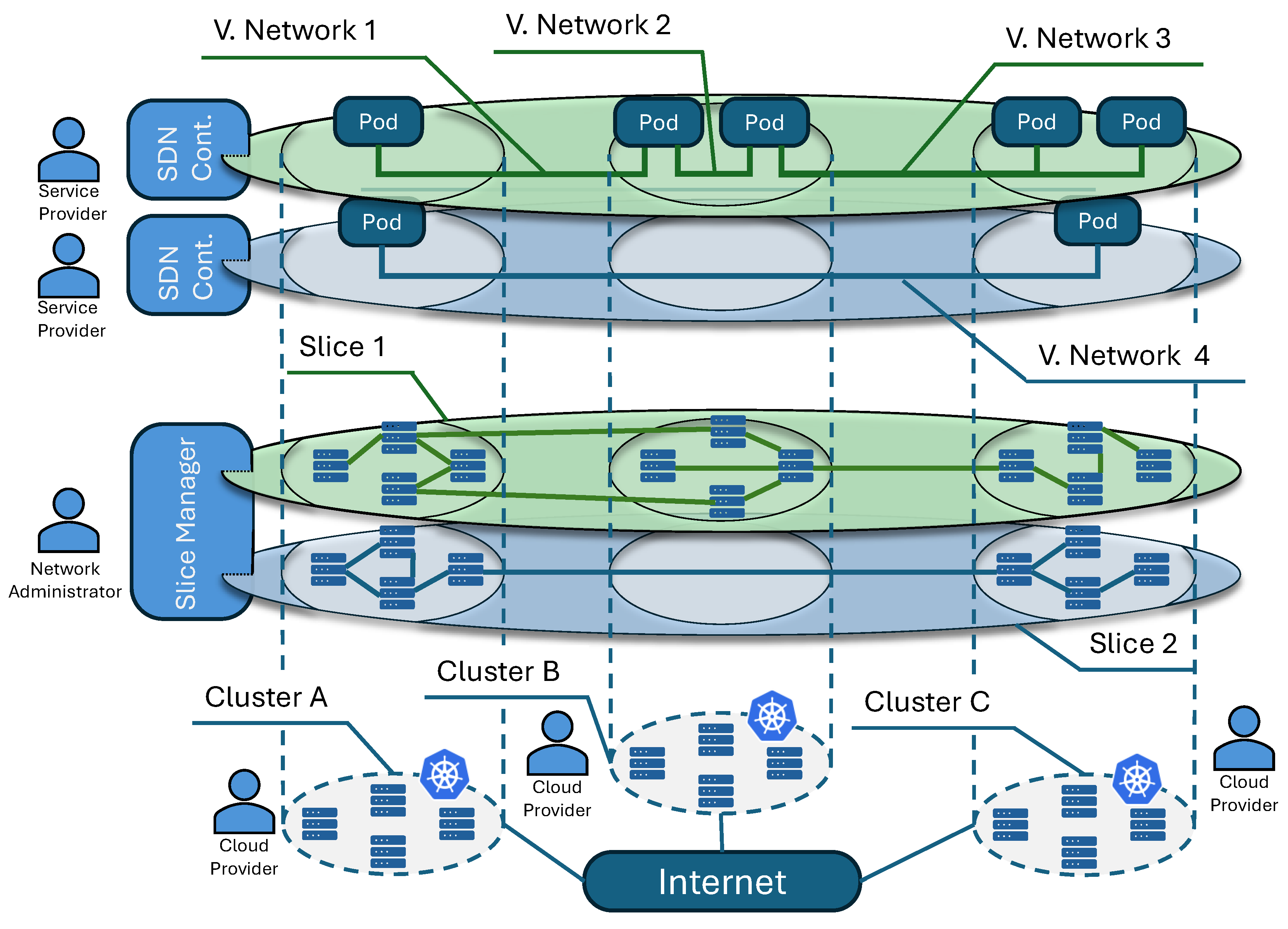
Figure 2.
Slice operation workflow.
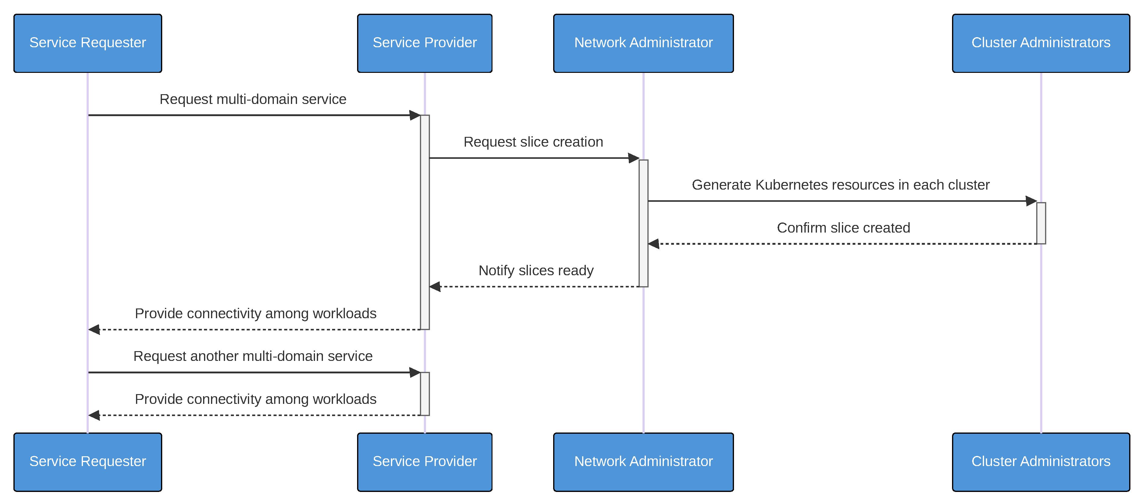
Figure 3.
Architectural overview.
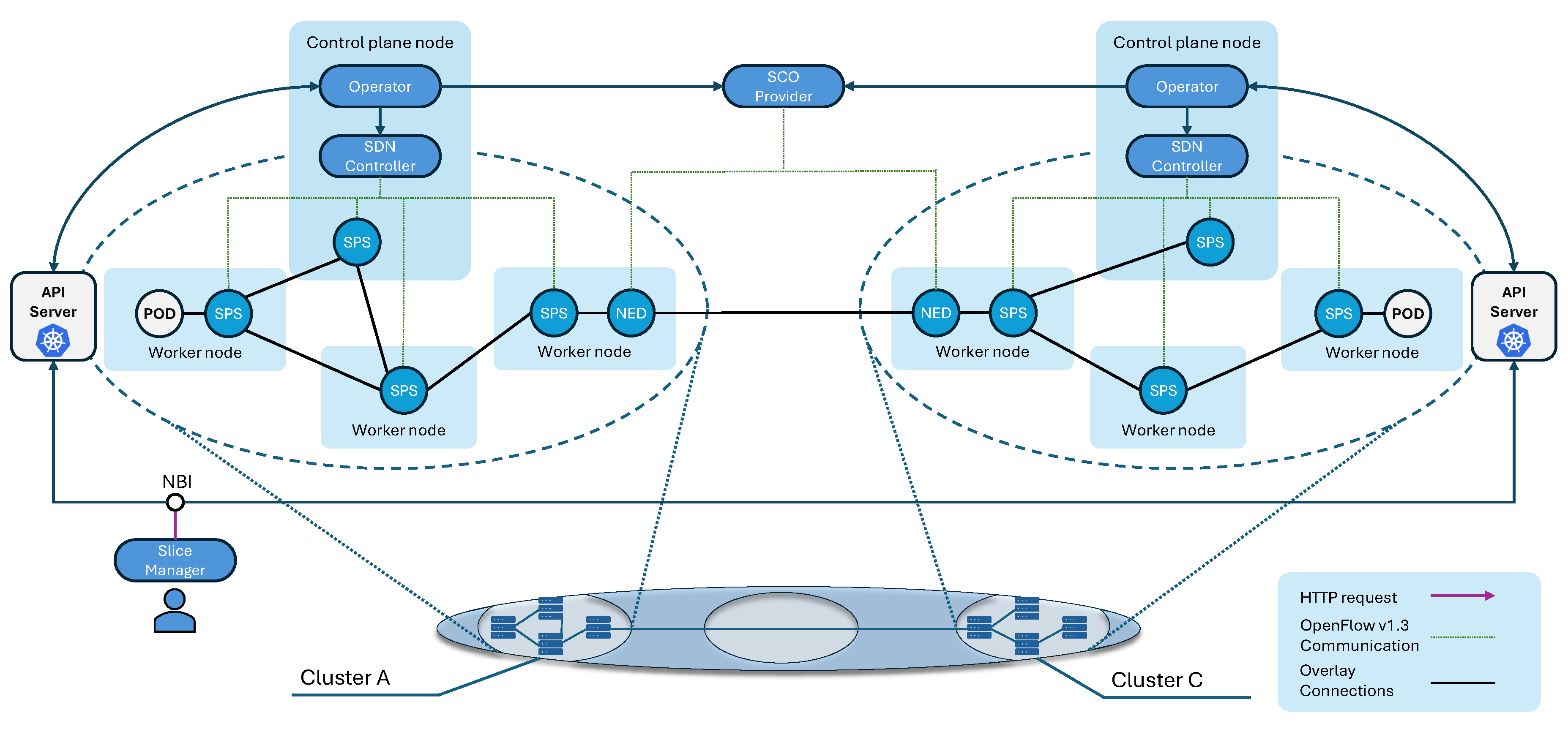
Figure 4.
Use case scenario where each cluster represents an entity.
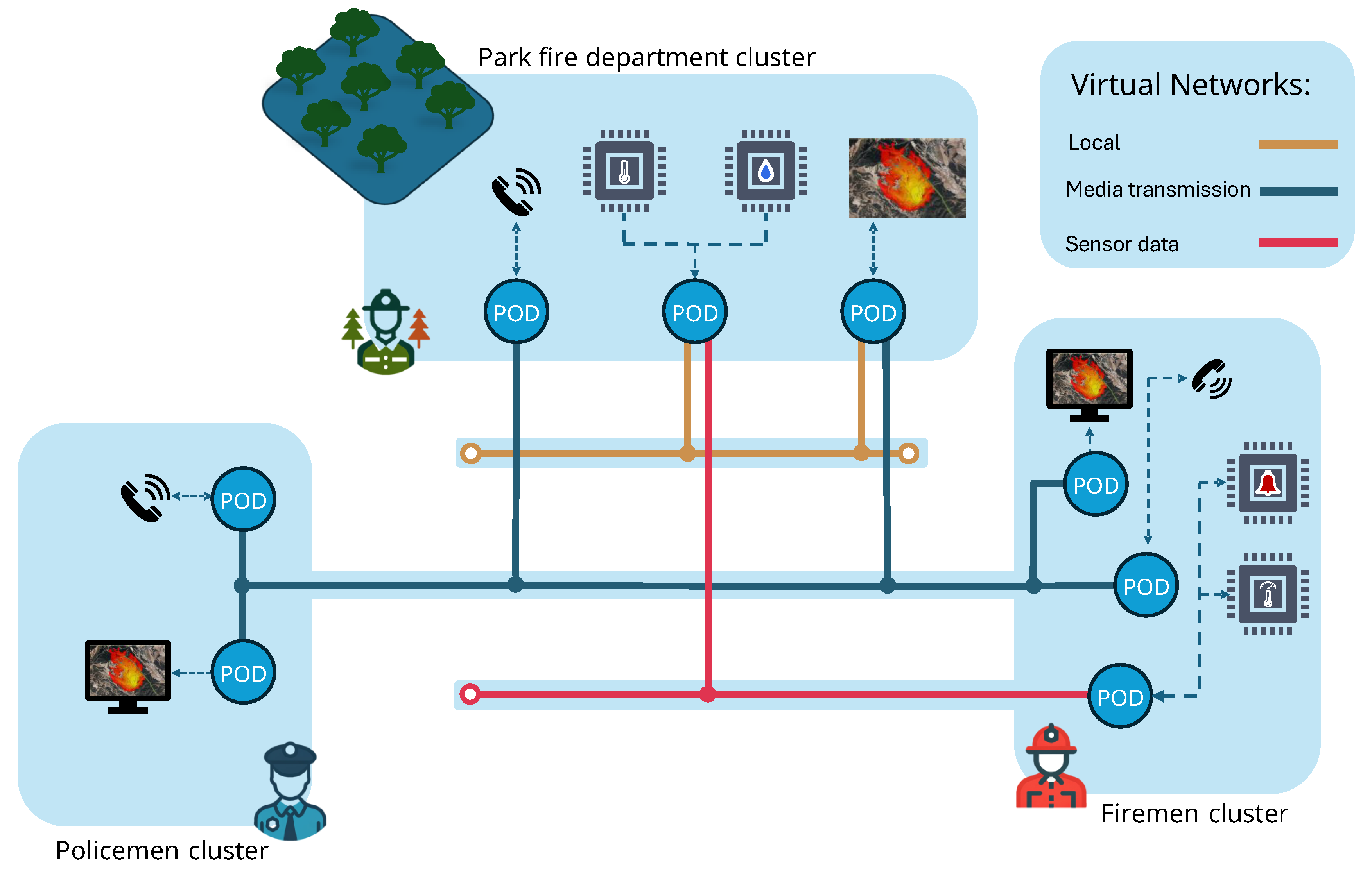
Figure 5.
Mean CPU usage (cores) by cluster.
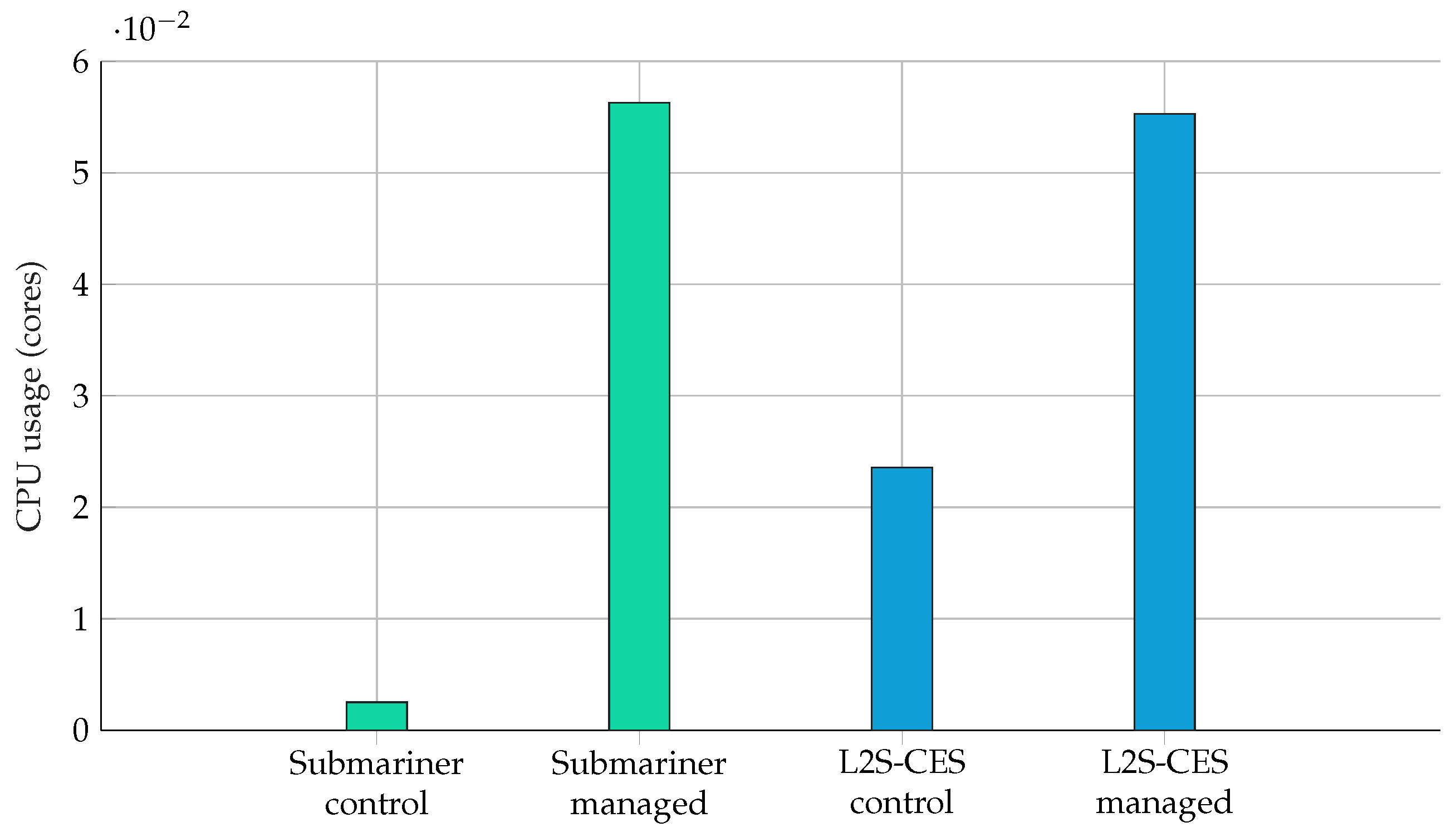
Figure 6.
Packets per second during the isolation test in Submariner vs. L2S-CES.
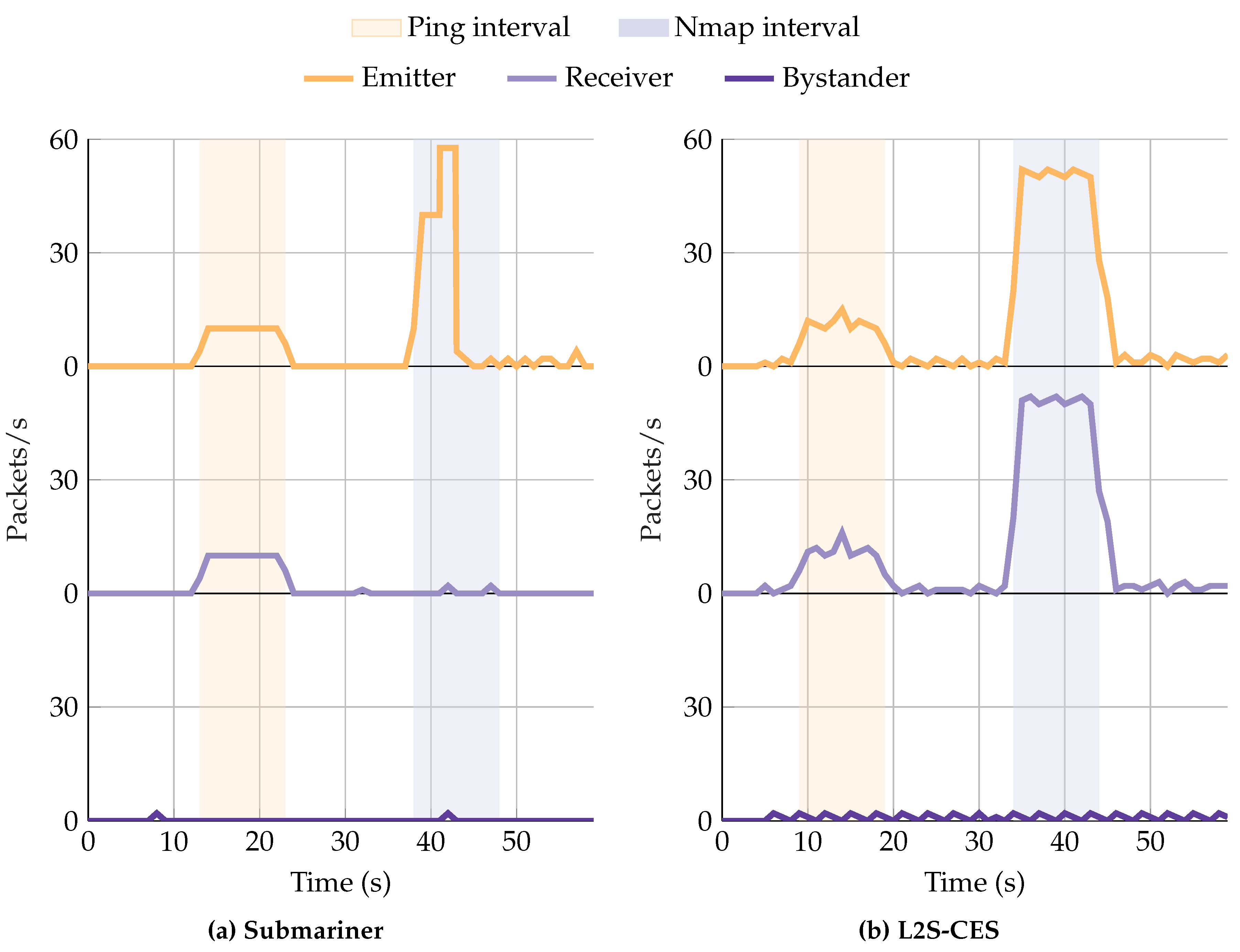
Figure 7.
Packets per second in Submariner vs. L2S-CES.
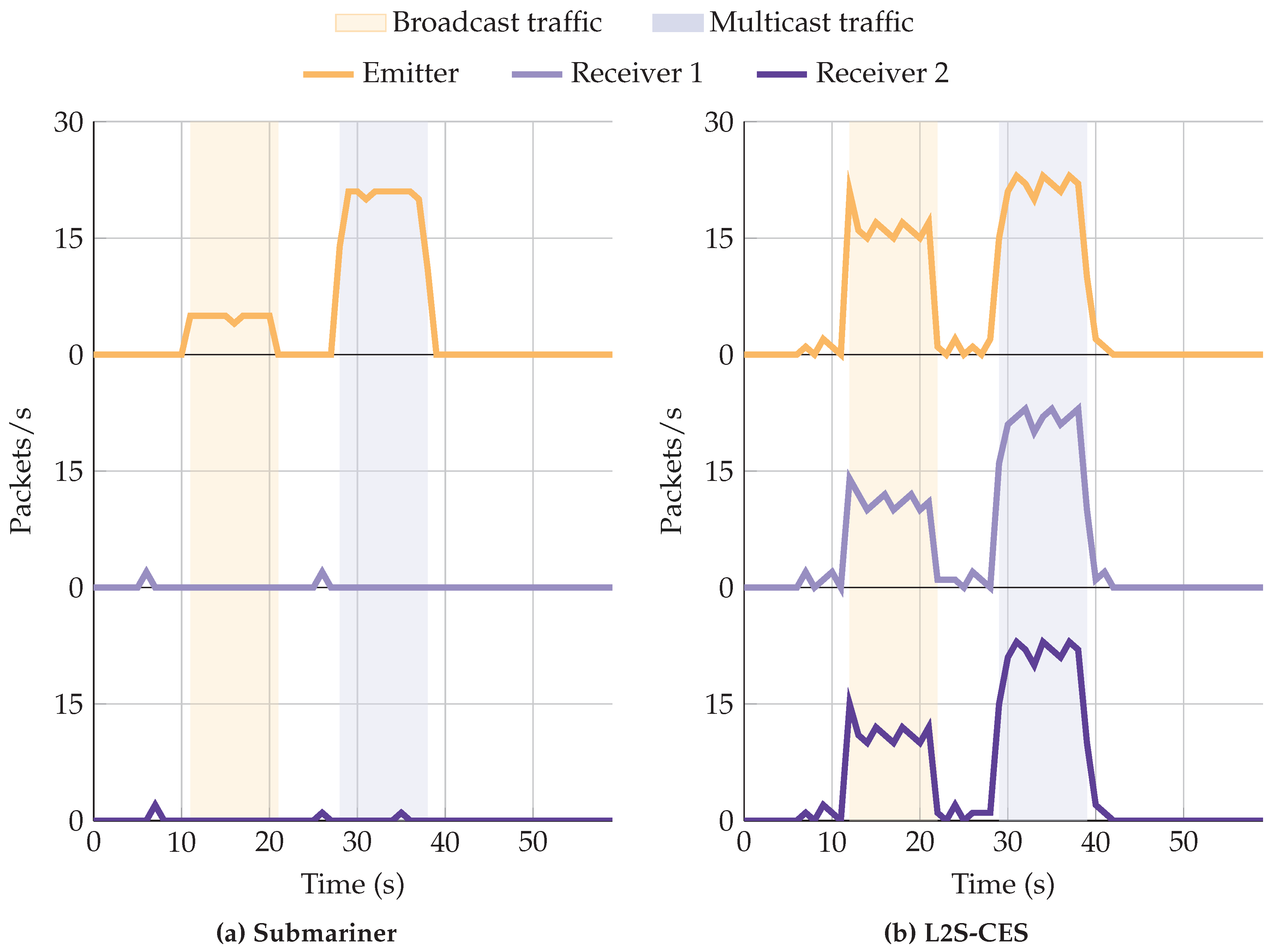

Table 1.
Comparison with other networking solutions
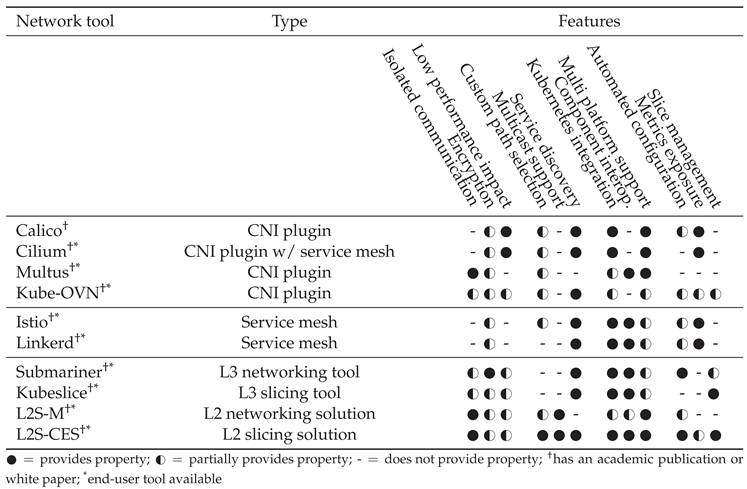
Table 2.
Cluster roles and components used in the evaluation testbed. Managed clusters have one control plane node and two worker nodes; the gateway is hosted on one of the workers.
Table 2.
Cluster roles and components used in the evaluation testbed. Managed clusters have one control plane node and two worker nodes; the gateway is hosted on one of the workers.
| Cluster | Nodes | Control plane components |
Per-node components |
Gateway-node components |
|---|---|---|---|---|
| l2sces-control | 1 | l2sces-client, sco-provider, l2sces-dns | — | — |
| l2sces-managed-1 | 3 | L2S-CES Operator, SDN controller | SPS per node | NED on 1 worker |
| l2sces-managed-2 | 3 | L2S-CES Operator, SDN controller | SPS per node | NED on 1 worker |
| sub-control | 1 | Submariner broker | — | — |
| sub-managed-1 | 3 | Lighthouse, Globalnet, Submariner operator | Route agent per node | Submariner gateway on 1 worker |
| sub-managed-2 | 3 | Lighthouse, Globalnet, Submariner operator | Route agent per node | Submariner gateway on 1 worker |
Disclaimer/Publisher’s Note: The statements, opinions and data contained in all publications are solely those of the individual author(s) and contributor(s) and not of MDPI and/or the editor(s). MDPI and/or the editor(s) disclaim responsibility for any injury to people or property resulting from any ideas, methods, instructions or products referred to in the content. |
© 2025 by the authors. Licensee MDPI, Basel, Switzerland. This article is an open access article distributed under the terms and conditions of the Creative Commons Attribution (CC BY) license (http://creativecommons.org/licenses/by/4.0/).
Copyright: This open access article is published under a Creative Commons CC BY 4.0 license, which permit the free download, distribution, and reuse, provided that the author and preprint are cited in any reuse.


