
Submitted:
20 November 2025
Posted:
21 November 2025
You are already at the latest version
Abstract
Underwater Vehicle-Manipulator Systems (UVMS) play a critical role in various marine operations, where the choice of manipulator architecture significantly influences system performance. While serial robotic arms have been widely adopted in UVMS applications due to their operational flexibility, their inherent structural characteristics present certain challenges in underwater environments. These challenges primarily stem from the cu-mulative effects of joint mechanisms and dynamic interactions with the fluid medium. In this context, we explore an innovative UVMS solution that incorporates the Delta parallel mechanism, which offers distinct advantages through its symmetrical architecture and unilateral motor configuration, particularly in maintaining operational stability. We de-velop a comprehensive framework that includes mechanical design optimization, imple-mentation of distributed control systems, and formulation of closed-form kinematic mod-els, with comparative analysis against conventional serial robotic arms. Experimental validation demonstrates the system's effectiveness in underwater navigation, target ac-quisition, and object manipulation under operator-guided control. The results reveal sub-stantial enhancements in motion consistency and gravitational stability compared to tra-ditional serial-arm configurations, positioning the Delta-based UVMS as a viable solution for complex underwater manipulation tasks. Furthermore, this study provides a compar-ative analysis of the proposed Delta-based UVMS and conventional serial-arm systems, offering valuable design insights and performance benchmarks to inform future develop-ment and optimization of underwater manipulation technologies.
Keywords:
underwater vehicle-manipulator systems
; delta parallel mechanism
; mechanical design optimization
; underwater target acquisition
0. Introduction
The Underwater Vehicle-Manipulator System (UVMS) is an advanced underwater robotic system designed for a wide range of tasks, including underwater observation, patrol, sampling, installation, welding, and other operational activities [1,2]. A typical UVMS comprises two primary components: underwater robot body and manipulator. During underwater operations, the underwater vehicle is responsible for transporting the manipulator to the desired location by using thrusters, while the manipulator, equipped with multiple degrees of freedom (DOF), ensures precise positioning and assists the end-effector in performing the required tasks. To facilitate these operations, UVMS units are typically equipped with cameras, providing visual feedback of the underwater environment, aiding in target localization, and guiding the execution of tasks [3]. Given the significant advantages in conducting unmanned underwater operations, UVMS technology is becoming increasingly important in fields such as deep-sea environmental monitoring, mineral exploration, and maritime rescue [4,5].
In recent years, a growing number of research teams have recognized the critical role of UVMS and have developed various models, including the SAUVIM [6] and GIRONA 500 [7]. As the motion carrier of UVMS, the design of the underwater vehicle plays a crucial role in determining its operational stability. Streamlined vehicle shapes, such as spherical, torpedo, and flat configurations, are often employed to minimize fluid resistance and enhance speed. However, these designs face inherent challenges, particularly with respect to the suppression of rolling and pitching motions, which are influenced by the structural characteristics of the vehicle, time-varying currents, and drift forces, especially when the vehicle is operating in a suspended state. Furthermore, the compact interior of streamlined underwater vehicles presents difficulties in accommodating essential equipment, including thrusters, end-effectors, and sensors. In contrast, rectangular (frame-type), flat-shaped underwater vehicles offer structural advantages in suppressing both transverse and longitudinal motions, thereby improving underwater maneuverability. Notable examples of such vehicles include the CR6000 [8] and Dex-ROV [9].
As the execution unit of UVMS, the manipulator's performance directly impacts efficiency and reliability underwater. Due to the advantages of serial robotic arm, such as simple control, large workspace and multiple DOF, it has been widely used in underwater unmanned systems such as MARIS 7080 [10], Schilling Titan 2 [11]. However, each kinematic joint of serial robotic arm requires a separate motor for drive and control, the transmission mechanism (gears, belts, etc.) introduces transmission and cumulative errors [12]. In addition, the limited speed of the serial robot arm affects its application in scenarios that require high-speed response and rapid motion. Furthermore, the embedded driving motors and transmission mechanism lead to a heavier weight of the arm, and the movement of the serial robotic arm during underwater operation leads to a change in the position of the center of gravity, which affects the stability and operational accuracy of UVMS.
Compared to serial robotic arms, parallel robotic arms, such as the Delta parallel robot, offer superior rigidity, effectively minimizing vibration and instability, thereby ensuring high operational stability and precision. The load can be evenly distributed across each motion arm, enabling the parallel robot to handle heavier payloads. Furthermore, as the drive motors and transmission mechanisms are not integrated within the individual arms but are instead located in the stationary base, the moving mass of the parallel robotic arm is significantly reduced. In the Delta parallel robot, the drive motors are symmetrically mounted on one side of the static platform, which reduces their impact on the underwater vehicle's center of gravity. Additionally, the parallel robot's rapid acceleration capabilities provide significant advantages in dynamic tasks such as underwater grasping and material transfer. Recently, numerous scholars have recognized the advantages of Delta parallel robots and conducted research on their applications in underwater environments. For example, Simoni et al. [13] proposed a lightweight Intervention-Autonomous Underwater Vehicle (I-AUV) equipped with a 6-DOF foldable and deployable Delta-type parallel manipulator, which is horizontally mounted on the front end of the vehicle. Deng et al. [14] developed a dynamic model for an underwater Delta parallel robot, analyzing the influence of hydrodynamic, kinematic, and structural parameters on the robot's motion trajectory and mechanical properties.
In real-world applications such as underwater mining, lighter systems with fewer DOF offer significant advantages, including enhanced operational efficiency, reduced mechanical complexity, and improved adaptability to challenging environments. The Eureka II deep-sea mining robot designed by Impossible Mentals company exemplifies these benefits [15], as it operates effectively within the tight space and weight constraints required for missions at depths of up to 6,000 meters. Despite its low DOF, the Eureka II's Delta parallel manipulator demonstrates exceptional precision, speed, and rigidity, enabling efficient and accurate mining in extreme deep-sea conditions. This application of a Delta-based mechanism in underwater missions serves as a strong feasibility validation, forming the foundation for the design of a more lightweight, Delta-based UVMS in this study.
This study proposes a flat-type UVMS based on Delta parallel mechanism to overcome stability limitations in underwater grasping tasks. Through kinematic modeling and workspace analysis, we established the theoretical framework and validated system performance via trajectory simulations and operational experiments. Delta-based UVMS configuration exhibits better motion stability than conventional Serial UVMS designs, significantly reducing hydrodynamic effects and improving end-effector precision during dynamic operations. The rest parts of this paper have been organized as follows. Section II presents the methodology of the Delta-based UVMS, detailing its mechanical architecture, control strategy, kinematic modeling, and comparative analysis with conventional serial-arm system. Section III implements experimental validation through targeted grasping tests and trajectory tracking experiments, evaluating both the Delta manipulator's operational performance and the vehicle's motion control capabilities. Section IV provides an in-depth analysis of the experimental results, including quantitative comparisons with existing UVMS configurations. The study concludes with key findings and implications in Section V.
1. Material And Methods
1.1. Mechanical design of the UVMS
Figure 1 shows the mechanical composition of the proposed UVMS, which can be divided into two parts: the upper floating-motion unit and the lower Delta gripper unit. The system is specifically designed to address the stability, robustness, and adaptability challenges encountered in deep-sea mining environments, where vehicles must operate reliably under high pressure, complex currents, and unpredictable sediment disturbances.
The upper floating-motion unit adopts a rectangular structure with multiple buoyancy blocks (material: polystyrene) arranged around the cylindrical capsule to ensure stability during vehicle movement. The integrated system exhibits positive buoyancy, as its total buoyancy exceeds gravitational force. Diving and ascending are achieved by modulating thrust from four centrally mounted vertical thrusters (Model 2820, ROV-maker Co., China) within the upper floating-motion unit. These vertical thrusters (T1–T4) simultaneously enable pitch and roll moment generation through differential thrust allocation. An additional quartet of thrusters, arranged symmetrically around the rectangular framework, provides horizontal translational control and yaw rotation. This 8-thruster configuration theoretically grants the floating-motion unit 6-DOF maneuverability, ensuring fine station-keeping and precise positioning—critical capabilities when conducting polymetallic nodule collection or sensor installation on rugged seabed.
To achieve precise manipulation of the lower Delta gripper unit, a waterproof binocular camera (ZF-USB-02B10, Zhi-fan Marine Equipment Co., China) is mounted on the floating-motion unit for real-time observation and illumination. The essential hardware components, including power supplies, motion controllers, camera drivers, and sensors, are enclosed within a sealed acrylic box, centrally positioned to minimize hydrodynamic interference. This modular design not only simplifies integration but also accommodates additional payloads such as sampling tools or mining-specific sensors, which are essential in deep-sea operations.
The lower Delta gripper unit is mechanically structured based on a 3-RS₂(Ps)S₂ mechanism, comprising a gripper and multiple interconnected subcomponents. Specifically, "R" denotes a rotational subcomponent, "S" represents a spherical subcomponent, and "Ps" refers to a parallelogram pivot chain formed by four spherical subs. The static platform is securely mounted on the upper floating-motion unit, while the dynamic platform integrates a flexible gripper. To ensure structural stability, the static and dynamic platforms, along with the active and passive arms, are interconnected via high-stiffness Hook hinges. Actuation is achieved through three high-performance motors (ZF-D60, Zhi-fan Marine Equipment Co., China), which are fixed to the static platform to drive the dynamic platform. This configuration enables the mechanism to achieve 3 translational DOF. The flexible gripper operates via a linkage mechanism actuated by additional motors, whose drivers are also housed within the sealed box to ensure environmental protection and system reliability. The Delta mechanism’s reduced moving mass and rigid closed-loop architecture are especially advantageous for grasping heavy, irregularly shaped mineral nodules, where stability and gripping precision directly determine extraction efficiency.
Since the UVMS operates in underwater environments, waterproofing is a crucial aspect of the system’s design. The system is designed for a depth of 300 m. Figure 1b illustrates the waterproofing strategy implemented in the proposed system. The binocular camera, IMU sensor, and the drive motors for both the Delta mechanism and gripper are rated IP68, ensuring suitability for prolonged submersion. As previously mentioned, all essential electronics, including the microcontroller board (Raspberry Pi) and Pixhawk 2.4.8, require robust waterproofing. These critical electronics were housed in a custom sealed box featuring an acrylic pressure-resistant capsule, complemented by a flange design with O-ring interference sealing. The assembly was further reinforced through dual epoxy applications, employing Epoxy Resin AB for structural bonding and Adhesive for perimeter sealing enhancement. This multi-layer waterproofing strategy is tailored for the highly corrosive and high-pressure deep-sea mining environment, ensuring continuous system reliability during long-duration operations.
All hardware devices are powered by a lithium battery, specifically a 6S-25C battery with a capacity of 16,000 mAh, capable of delivering a maximum power output of 2000 W to the UVMS. Under this configuration, the gripper drive motor can achieve a maximum effective gripping force of approximately 25 kg with the torque of 2 Nm. Each thruster provides a maximum thrust of 2 kg, and the selected robotic arm servo can generate a gripping force of up to 25 kg, significantly exceeding the propeller’s thrust. Consequently, considering the combined thrust of all four thrusters (4 × 2 kg), the maximum estimated weight of an object that the UVMS can effectively grasp is 8 kg. This payload capability is sufficient for typical polymetallic nodules, which range from several hundred grams to several kilograms, thus meeting the practical requirements of deep-sea mineral collection. Additional relevant technical parameters are summarized in Table 1. for further reference.
1.2. Control System and Control Strategy
Figure 2a illustrates the control system framework and key equipment of the proposed UVMS, which consists of two main sections: the ground control section and the underwater actuation section. Considering the extreme conditions of deep-sea mining—such as high-pressure environments, complex hydrodynamics, and low-visibility due to suspended sediments—the control system emphasizes robustness, redundancy, and adaptive data fusion.
A custom user interface, developed using Python, enables control of the UVMS from a standard PC and joystick guided by video images and sensor data provided by the interface. Key operational data, such as images, angles, and poses, are stored in real time for post-mission analysis and system optimization. The microcontroller board (Raspberry Pi) performs the kinematic calculations of the Delta robot and streams binocular camera video, while communication with the console is established via TCP/IP.
The Pixhawk 2.4.8 serves as the execution unit, integrating an electronic compass, Inertial Measurement Unit (IMU), Doppler Velocity Logger (DVL), and altimeter. This integration is crucial for deep-sea mining tasks, where reliable localization and station-keeping are essential to prevent sediment plumes from disrupting visibility or to avoid damaging valuable mineral deposits. The Raspberry Pi pre-compiles and executes the code responsible for controlling motors and servos, functioning as the central controller. It receives commands from the Ground Control Section via the umbilical cable, processes these inputs, and generates RC and PWM signals for the Pixhawk. These signals precisely actuate thrusters and Delta robot joints. The binocular camera, connected via USB 4.0, captures real-time images of the working environment. This dual-layer control architecture enhances fault tolerance, ensuring continuity of operations even under the unstable communication conditions often encountered in deep-sea missions.
Figure 2b presents the control strategy implemented in the proposed UVMS. The system leverages a binocular camera for real-time target recognition, supported by image processing steps including calibration, aberration correction, and stereo matching. The YOLO v5 vision algorithm is employed to extract the target’s 3D coordinates, which are then processed by the control program on the Raspberry Pi. This vision-guided recognition is especially valuable in deep-sea mining scenarios where targets such as polymetallic nodules are partially buried in sediment and must be discriminated from background rocks and biological organisms.
The UVMS attitude is stabilized using PID control algorithms, with real-time adjustments facilitated by the Pixhawk’s IMU and DVL. This closed-loop stabilization strategy ensures that the UVMS maintains a fixed orientation despite ambient currents, enabling precise and repeatable manipulations critical for harvesting fragile mineral nodules without causing seabed disturbance. Once stabilized, the system executes pick-and-place operations based on motion planning algorithms that optimize arm trajectories within the underwater workspace.
Figure 3 illustrates the control block diagram for target capture. If the 3D coordinates of the recognized target fall within the predefined operational workspace, the recognition frames on the host computer turn blue, and the controller computes the necessary joint rotations of the Delta gripper. Conversely, if the target lies outside the workspace, the recognition frames turn red, indicating inaccessibility. This boundary-based visual feedback not only prevents futile manipulations but also supports task planning in deep-sea mining, where time and energy efficiency are paramount due to limited battery capacity and mission windows.
1.2. Kinematic Analysis of the UVMS
To analyze the positional relationship of the manipulator with respect to the underwater vehicle and to determine the response to the motor driving angles, the inertial frame E:(xE,yE,zE), the body frame B:(xB,yB,zB), the static platform frame S:(xS,yS,zS) and the dynamic platform frame D:(xD,yD,zD) are established to develop the kinematic model of the UVMS, as shown in Figure 4.
The body, static and dynamic frames are built at the upper floating-motion unit center, the static platform center and the dynamic platform center, respectively. The center position B of the upper floating-motion unit in the inertial frame can be expressed as:
whereare the positions of the upper floating-motion unit center and the dynamic platform center in the inertial frame, andare the roll, pitch and yaw angles of the upper floating-motion unit in the inertial frame, respectively.
The transformation relationship between the body frameand the inertial coordinate system can be expressed as:
whereand
The static platform of the lower Delta gripper unit is fixed to upper floating-motion unit, and the relationship between the static frame with the body frame and the center point of the dynamic platform in the static frame can be represented as, the relationship can be expressed as:
Thus, the relationship between the dynamic frame and the inertial frame can be expressed as: . The positional relationship between the center S of the static platform and the center D of the dynamic platform can be obtained by analyzing one of the closed-loop branch D-M1-N1-P1-S of the Delta parallel robot, whose vector form can be expressed as:
The individual vectors in the static frame can be denoted as:
where R is the radius of static frame, L1 is the length of the active arm of the Delta parallel robot, is the angle between the static platform and the active arm, the angle β between each branched chain and xS axis can expressed as:Since the length of the passive arm is fixed, i.e., the distance L2 between Ni and Pi is constant, accordingly, the following kinematic equations are obtained:
where is the radius of dynamic frame, L2 is the length of the positive arm of the Delta parallel robot, .
If the angle of the active arms is known, the position of the dynamic platform with respect to the upper floating-motion unit can be obtained from the above equations. On the contrary, if the point is known, the corresponding angle θi of the active arms can be obtained by the inverse kinematic solution.
1.2. Kinematic Analysis of the UVMS
To quantitatively evaluate the stability advantages of the Delta parallel UVMS over the conventional serial UVMS, dynamic simulations were performed using Adams software. Both systems were modeled with identical geometric dimensions of 550 mm × 400 mm × 700 mm, 6-DOFs, buoyancy-to-weight ratios of 1.05, and open-loop trajectory tracking control parameters. As illustrated in Figure 5a, both configurations executed predefined “∩” and “∞” trajectories under uniform floating-state conditions (see Figure 5b), where only gravity, buoyancy, and hydrodynamic forces were considered. Thruster-based PID compensation was intentionally disabled to isolate the intrinsic mechanical effects of the manipulator designs.
Figure 5c,d presents the hydrodynamic forces acting on the upper floating-motion unit. During “∞” trajectory execution, the serial UVMS experienced peak forces of ~8.8 N, while the Delta UVMS recorded a markedly lower peak of 4 N. Although both systems exhibited comparable maximum forces during the “∩” trajectory, the serial configuration sustained a consistently higher average force, inducing greater perturbations in body displacement. Torque analysis further revealed that the serial system generated more substantial z-direction torques, adversely affecting angular stability. By contrast, the Delta UVMS exhibited a more uniform torque distribution, thereby reducing angular deviations.
From a deep-sea mining perspective, this reduced hydrodynamic disturbance is critical, as excessive forces and torques not only compromise vehicle stability but also exacerbate sediment plume generation near the seabed, obscuring visual sensors and jeopardizing sustained mining operations. The Delta parallel structure inherently mitigates such perturbations, ensuring more stable body dynamics in unstructured environments.
Figure 6. compares the trajectory tracking performance of both systems. During “∩” trajectory execution (Figure 6a), the Delta manipulator outperformed its serial counterpart across all axes. For example, in the x-direction, the maximum deviation of the Delta system was ~45 mm, compared to ~227 mm for the serial manipulator. During the “∞” trajectory (Figure 6b), both systems achieved comparable x-direction accuracy, yet the Delta UVMS demonstrated smaller y-axis (39.7 mm vs. 59.5 mm) and z-axis (3.2 mm vs. 10.1 mm) deviations.
These improvements stem from the structural alignment of the Delta manipulator, which extends vertically downward beneath its base, enabling motions that are naturally aligned with the vehicle body. Although this introduces challenges in precise z-direction control, the overall three-dimensional error accumulation remained significantly lower than that of the serial configuration.
The comparative results underscore the engineering significance of the Delta parallel design for deep-sea mining applications. Superior hydrodynamic stability reduces plume disturbances and enhances vehicle station-keeping, while improved trajectory tracking ensures reliable grasping of polymetallic nodules and other seabed resources under strong ocean currents. Moreover, the reduced torque fluctuation lowers mechanical stress on joints and actuators, thereby enhancing system durability and energy efficiency, both of which are vital in long-duration autonomous mining missions.
2. Experiment Results
2.1. Mechanical Performance of the Lower Delta Gripper Unit
As previously mentioned, the dexterity of the Delta gripper unit is a key feature of the system. To quantitatively evaluate the kinematic accuracy of the fabricated Delta robot, an HTC VIVE tracker 2.0 (Hongda International Electronics Co., Ltd., China) was mounted on the dynamic platform for precise measurements (see Figure 7a). In land-based experiments, presented in Figure 7c,d, demonstrate that the Delta robot could follow predetermined trajectories with a maximum deviation of 6.4 mm. This deviation can be attributed to factors such as friction variations due to insufficient lubrication among the rods and inaccuracies in position and velocity control, which occasionally led to arm decoupling. Enhanced lubrication and refined control algorithms are expected to reduce these discontinuities. However, the current level of trajectory-following precision is deemed sufficient for the operational requirements of underwater vehicle-manipulator systems.
To further evaluate the system’s performance, target grasping experiments were conducted using a soft-bodied sea cucumber model as the target. The lower Delta gripper unit was controlled via a joystick, with real-time guidance provided by binocular camera images displayed on the PC interface (see Figure 7b). Across five independent trials, the gripper was able to reach the target localization accurately. However, the compliant dexterity of the soft gripper resulted in successful target acquisition in four out of five attempts (80% success rate), with a mean positioning-to-grasp duration of 7.9 ± 1.3 seconds.
2.2. Kinematic Performance of the Upper Floating-Motion Unit
The proposed UVMS employs thruster-based actuation, utilizing coordinated control of eight propulsion units to achieve full 6 DOF maneuverability within its floating-motion module. This configuration enables precise spatial control through differential thrust allocation, essential for the underwater manipulation required in deep-sea mining, where translation along the x, y, and z axes, as well as yaw, are the dominant degrees of freedom (DOFs). Roll and pitch stabilization is inherently supported by the vehicle’s structural design, which ensures stability under varying operational conditions. For deep-sea mining, where precision and stability are paramount to the successful extraction of underwater resources, the ability to manage these key DOFs is essential.
To evaluate the kinematic performance of the UVMS, a series of experiments were conducted in a controlled experimental pool. As shown in Figure 8a, the proposed UVMS demonstrated impressive flexibility and maneuverability. During underwater operation, the stable attitude of the upper floating-motion unit plays a critical role in enhancing the reliability of the lower Delta gripper assembly, which is crucial for grasping and manipulating materials from the seabed in a controlled manner. The Delta gripper’s ability to maintain a precise grasp, free from body displacement or instability, significantly contributes to the operational success of deep-sea mining.
In this study, an IMU-based PID feedback control algorithm was implemented to control the floating-motion unit, ensuring stability during operation. To validate the effectiveness of this control strategy, comparative experiments were conducted with and without PID control. The experimental setup is shown in Figure 8b,c, with the waterproof angle sensor (HWT901B-TTL, WIT Co., China, IP68 waterproof rating) placed at the top center of the vehicle’s body to monitor angular variations along the x, y, and z axes during the trajectory execution. The experiments were grouped as follows: a control group with a fixed stationary body, an experimental group with a floating body using open-loop control, and an experimental group with a floating body utilizing PID control. The Delta robotic arms were controlled to follow a predefined "∩" trajectory during the trials.
The body angle curves (see Figure 8d) demonstrate the effectiveness of the PID control strategy. In the fixed body group, the angular variations remained close to 0° across all three axes, as expected. However, the open-loop experimental group exhibited more significant angular changes, with the variation ranging from -1.58° to 2.12°. In contrast, the PID-controlled group showed reduced angular fluctuations, ranging from -0.33° to 0.66°, underscoring the stability provided by the PID control system.
These results highlight a key advantage of the Delta mechanism-based UVMS in deep-sea mining applications: even without PID control, the system's closed-chain kinematic structure maintains body orientation stability, with angular deviations kept within 2.12°. This closed-chain design distributes dynamic loads symmetrically across its linkages, minimizing torque imbalances that could lead to body rotation or displacement. Such stability is crucial for deep-sea mining, where even minor deviations in vehicle orientation could lead to significant errors in material handling, potentially damaging equipment or causing resource misplacement.
The ability to execute precise trajectories while maintaining a stable body orientation, even in dynamic underwater environments, is a significant advantage for the proposed UVMS in the context of deep-sea mining. As underwater excavation and material collection often involve interaction with the seabed, any displacement of the vehicle body could lead to suboptimal performance and increased risks of failure. The stable attitude control provided by the PID feedback algorithm and the inherent structural stability of the Delta mechanism ensure that the UVMS can maintain its operational position, thus enhancing the reliability and precision required for extracting valuable resources from the ocean floor.
The improved stability and accuracy of the proposed UVMS, especially in maintaining orientation during operational tasks, positions it as a highly viable option for the next generation of deep-sea mining systems. By reducing disturbances and ensuring reliable grasping of materials, the system ensures more efficient and safer underwater resource extraction, crucial for long-duration missions in deep-sea mining operations.
2.3. Underwater Grasping Experiment
As described above, the proposed UVMS demonstrates the capability to perform underwater grasping tasks with the assistance of a binocular camera. To validate its effectiveness, a series of grasping experiments were conducted using a sea cucumber model. The grasping process, supported by binocular vision, unfolds as follows: Initially, the UVMS is maneuvered via PC and joystick control to approach the target, ensuring it enters the binocular camera's recognition range. A predefined boundary range is established within the workspace of the lower Delta gripper unit, with these boundary points integrated into the binocular recognition algorithm to assess the feasibility of the grasping operation. If the target lies outside the Delta robot's workspace, the recognition frame turns red, prompting the UVMS to autonomously adjust its attitude and reposition the Delta robot within the workspace. The capture logic, detailed in Figure 3 of Section II B, illustrates this process, emphasizing the role of the upper floating-motion unit in adjusting its position until the target is within the operational workspace of the Delta gripper unit.
The experimental setup and results for underwater grasping of the targets model are presented in Figure 9a. The UVMS was controlled to grasp, transfer, and place the target, with motion data of the gripper acquired using position sensors. The results demonstrate that the UVMS can successfully grasp targets (e.g., sea cucumber, steel pipe) and transfer them to specified locations under binocular camera guidance (see Figure 9b–e). However, hydrodynamic forces generated by the movement of the lower Delta gripper unit induce attitude changes in the upper floating-motion unit, necessitating real-time thruster adjustments to maintain positional stability. This dynamic coupling between manipulator actuation and platform stability resulted in a 60% success rate (6/10 trials) in underwater grasping attempts with a mean task duration of 12.7 ± 3.1 seconds, which is significantly longer than terrestrial counterparts.
3. Discussion
In this study, we present an innovative UVMS based on the Delta parallel mechanism. A comparative analysis with other UVMS systems, as summarized in Table II, reveals that the proposed Delta-based UVMS offers distinct advantages in weight reduction and operational stability for underwater tasks. The bottom-mounted robotic arm effectively mitigates stability interference on the buoyancy body, addressing the stability challenges associated with lateral configuration [13]. Meanwhile, compared with the traditional torpedo or spherical floats [13,16], the flat-type floats show better static stabilization characteristics, which provides a basic guarantee for underwater operations. Although serial robotic arms [6,16] provide increased degrees of freedom and a larger workspace, their inherent weight and the substantial shift in the center of gravity during operation pose challenges to UVMS stabilization during underwater tasks. In contrast, the Delta parallel mechanism minimizes these issues, enhancing system stability. Compared to commercial bottom-mounted system like the Eureka II [15], the proposed UVMS features a simpler mechanical structure while achieving human-machine interaction through vision-based visual servo autonomous grasping and joystick-based control modes. Notably, while preliminary functionality has been validated through land-based and underwater experiments, the system's reliability under dynamic marine conditions, including turbulent disturbances and biofouling effects, requires quantitative evaluation through systematic sea trials. Combining target pose prediction model inspired by [17] to build a collaborative system that combines IMU-based vehicle control with anticipatory motion planning can improve the grasping success rate in complex underwater environments, which requires further research.
The constructed Delta gripper unit could move along the predetermined trajectories, but some disruptions occurred during the execution of the experiments (see Fig.7(c, d)). This phenomenon can be attributed to several factors, including variations in friction and inaccuracies in controlling the position and velocity of the arms. To address these issues, optimized control strategies, such as the pick-and-place operation trajectory planning method [18] and the simultaneous control-and-identification method [19], helping reduce discontinuities, resulting in improved velocity and acceleration behavior. However, further investigation is required to refine these methods for better performance. Nevertheless, for current UVMS, IMU-based float control and grasping operations assisted by binocular camera navigation can fulfill the basic requirements for underwater operations.
The workspace of the Delta parallel robot can be further increased by increasing the length of individual rods. Extending the rod length to enlarge the workspace involves trade-offs, including reduced precision due to increased deflection, added weight, and potential decreases in payload capacity. These factors necessitate careful consideration, as they impact actuator requirements, structural integrity, and overall system efficiency. However, it is important to note that the active and passive arms should be increased in the ratio of 0.58 [20], which is the golden ratio that maintains the best kinematic performance of the Delta Parallel Machines.
The underwater grasping experimental results show that it is a challenge to keep the underwater vehicle absolutely stable in suspension. This is attributed to the strong coupling within the Delta manipulator vehicle-water multibody and fluid system, which arises from the dynamic motion of the Delta manipulator. Furthermore, the propellers cause water to flow in particular directions makes the upper float-motion unit subject to more compact hydrodynamic force. This represents a complex hydrodynamic coupling issue commonly encountered in UVMS, which cannot be effectively addressed through basic PID control alone. Therefore, further research is required to develop synergistic optimal control strategies. In the future, it is necessary to establish a dynamic model of UVMS considering hydrodynamics and optimize the control system accordingly, so as to improve the stability of the underwater vehicle by optimizing the thrust distribution.
A comparative analysis of task completion times between underwater and terrestrial environments reveals that underwater manipulation tasks inherently take longer due to fluid resistance, which significantly affects manipulator speed and precision. Hydrodynamic forces, such as drag and buoyancy fluctuations, introduce delayed response times and reduced operational efficiency, requiring additional control effort from the operator. This increased cognitive load underscores the need for optimized control strategies and assistive automation to enhance the precision and efficiency of underwater manipulation.
Regarding the 40% grasping failure rate in underwater grasping experiment, it arises from multifactorial causes, with the reliability of the mechanical gripper being the predominant factor. While the soft gripper can successfully prevent target object damage, its inherent flexibility is not enough to support its grasping. Redesigning the contact geometry of gripper from planar to curved wraps, implementing variable stiffness modulation to dynamically adapt to load requirements, and increasing the gripper’s angular range of motion to expand its operational envelope all contributed to improved grasping success. Unlike terrestrial applications, hydrodynamic forces induced by robotic arm motion in underwater compromise the stability of its floating platform, leading to grasping failure, which is one of the reasons for the reduced success rate. To mitigate the impact of robotic arm motion on floating structures, we developed a downward-mounted Delta parallel mechanism and conducted dynamic simulations under identical operational conditions with a comparable serial manipulator. Comparative simulation results demonstrated that the Delta parallel manipulator exhibits reduced destabilizing effects on the floating body. To further minimize operational impacts, a PID control algorithm was implemented and underwater comparison experiment without PID control was carried out. The empirical findings confirm that PID-controlled actuation improves stabilization performance. The floating body oscillations also affect the visual localization accuracy of binocular camera, which in turn has an impact on the success rate of grasping. While template matching methods (e.g., SIFT, ORB) could partially mitigate these effects, such computational enhancements remain beyond the current scope of this study. Regarding challenges posed by limited underwater visibility and turbidity, structured light-based 3-D reconstruction techniques can improve navigation precision in conditions of reduced water clarity and increased particulate concentration

Table 2.
Comparison with other light Underwater Vehicle Manipulator Systems with robotic arms.
| Parameters | Yeu et al.[6] | Mario et al. [16] | Simoni et al. [13] | Eureka II [15] | Yang et al. [17] | This work |
| Body Shape | Flat | Torpedo | Torpedo | Flat | Flat | Flat |
| Body size(m) | 1.2 × 0.9×1.1 | 1.0×1.0×1.5 | 1.0×1.0×1.5 | 3.2×1.95×1.93 | - | 0.3*0.4*0.55 |
| Depth rating(m) | - | 300 | - | 6000 | - | 300 |
| System Weight(kg) | 230 | <200 | <200 | 3950 | 21.9 | ≤30 |
| Robotic arm type | Serial | Serial | Parallel (Delta) | Parallel (Delta) | Parallel (Delta) | Parallel (Delta) |
| Arm position | Bottom front | Body front | Body front | Bottom below | Bottom below | Bottom below |
| Arm DOF | 7 | 5 | 3 | 3 | 3 | 3 |
| Arm maximum elongation (m) |
1.4 | 1 | 1.2 | - | 0.68 | 0.52 |
| Arm weight(kg) | 51 | 29 | - | - | 0.7 | 0.8 |
| payload capacity(kg) | 25 | 12 | - | 100 | - | 8 |
| Controller | ROS | ROS | Micro PIC | - | Pixhawk,STM32 | PixhawkRaspberry Pi |
| Sensors equipped | IMU, DVL,Depth sensor et al. | DVL, AHRS,Camera et al. | DVL, AHRS,Camera et al. | - | IMU, Depth sensor,Camera et al. | IMU, DVL,Binocular Camera |
| Prototyping(Y/N) | Y | Y | N | Y | Y | Y |
4. Conclusions
This study presents an UVMS integrated with a Delta parallel robot, designed for marine exploration and intervention tasks. The Delta manipulator is mounted beneath the vehicle, capitalizing on its parallel architecture to minimize weight while enhancing structural rigidity, payload capacity, and stability in high-dynamic underwater environments. A comparative analysis of the Delta-based UVMS against conventional serial-manipulator UVMS highlights its superior operational stability, as demonstrated through dynamic simulations in Adams software. Experimental trials confirm the Delta manipulator’s ability to execute rapid dynamic responses and high-precision trajectory tracking, while the vehicle demonstrates proficiency in both fundamental maneuvers and advanced operations such as obstacle navigation. Motion control is achieved via an integrated robust PID controller with disturbance rejection capabilities, ensuring precision under hydrodynamic uncertainties. The system’s operational efficacy is further validated through binocular vision-guided object grasping and relocation tasks, demonstrating exceptional resilience to hydrodynamic disturbances. Successful emulations of seabed sampling and equipment maintenance scenarios underscore the UVMS’s potential for complex underwater interventions, highlighting its applicability in demanding marine operations.
Author Contributions
Conceptualization, Z.X., Y.Z., Z.C. and H.W.; methodology, Z.X., B.H., Y.B. and C. Z.; software, Z.X. and B.H.; validation, Y.Z., C.Z.; formal analysis, Z.X., B.H. and Y.F.; investigation, P.N.; resources, Z.X. and P.N.; data curation, B.H.; writing—original draft preparation, Z.C.; writing—review and editing, H.W. and Z.C.; visualization, Z.C. and Z.X.; supervision, Z.C. and H.W.; project administration, Z.C.; funding acquisition, Z.C. and H.W. All authors have read and agreed to the published version of the manuscript.
Funding
This research was funded by the National Natural Science Foundation of China, grant number 52305040, the China Postdoctoral Science Foundation, grant number 2023M733340, Independent Research Projects for Doctoral Students at Ocean University of China, grant number 202561071, the Shandong Province Natural Science Foundation of China, grant number ZR2023QE161, the Open Project Program of Shandong Marine Aerospace Equipment Technological Innovation Center, Ludong University, grant number MAETIC202203.
Institutional Review Board Statement
Not applicable.
Informed Consent Statement
Not applicable.
Data Availability Statement
This section is not mandatory but may be added if there are patents resulting from the work reported in this manuscript.
Acknowledgments
The authors would like to thank the members of the Marine Electromechanical Systems Research Institute for their continued support and discussion.
Conflicts of Interest
The authors declare that the research was conducted in the absence of any commercial or financial relationships that could be construed as a potential conflict of interest.
References
- Petillot, Y.R.; Antonelli, G.; Casalino, G.; Ferreira, F. Underwater robots: from remotely operated vehicles to intervention-autonomous underwater vehicles. IEEE Robotics & Automation Magazine. 2019, 26, 94–101. [Google Scholar]
- Huang, H.; Bian, X.; Cai, F.; Li, J. A review on visual servoing for underwater vehicle manipulation systems automatic control and case study. Ocean Engineering. 2022, 260, 112065. [Google Scholar] [CrossRef]
- Francisco, B.F.; Jordi, L.; Gabriel, O.C. Evaluating the impact of sewage discharges on the marine environment with a lightweight AUV. Marine Pollution Bulletin. 2018, 135, 714–722. [Google Scholar]
- Simpkins, C.A. ; Introduction to Autonomous Manipulation: Case study with an underwater robot, SAUVIM [On the Shelf]. IEEE Robotics & Automation Magazine. 2014, 21, 109–110. [Google Scholar]
- Pere, R.; Marc, C.; David, R.; Pedro, J.S.; Gabriel, O. Intervention AUVs: The next challenge: Annual Reviews in Control. 2015, 40, 227–241.
- Yeu, T.K.; Lee, J.; Lee, Y.G.; and Yoon, S.M. Preliminary Study on Identification of ROV for autonomous manipulation, OCEANS 2019 - Marseille, Marseille, France, pp. 1–6.
- Fossen, T.I.; Pettersen, T.I.; Galeazzi, R. Line-of-Sight path following for dubins paths with adaptive sideslip compensation of drift forces. IEEE Transactions on Control Systems Technology 2015, 23, 820–827. [Google Scholar] [CrossRef]
- Park, J.Y.; Shim, H.; Jun, B.H.; Baek, H.; and Lee, P.M. Design of tether cable for a deep-sea walking ROV, Crabster CR6000, OCEANS MTS/IEEE Charleston, Charleston, SC, USA, 2018, pp. 1–4.
- Lillo, P.D.; Simetti, E.; Wanderlingh, F.; Antonelli, G. Underwater intervention with remote supervision via satellite sommunication: Developed control architecture and experimental results within the Dexrov project. IEEE Transactions on Control Systems Technology. 2020, 29, 108–123. [Google Scholar] [CrossRef]
- Giacomo, M.; Song, K.C.; Junku, Y. Underwater autonomous manipulation for intervention missions AUVs. Ocean Engineering. 2008, 36, 15–23. [Google Scholar]
- Satja, S.; Matija, R.; Joseph, C.; Gerard, D. Fully automatic visu servoing control for work-class marine intervention ROVs. Control Engineering Practice. 2018, 74, 153–167. [Google Scholar]
- Bezanson, L.; Reed, S.; Martin, E.M.; and Barbalata, C. Coupled Control of a Lightweight Rov and Manipulator Arm for Intervention Tasks, OCEANS–Anchorage, IEEE. 2017. pp. 1–6.
- Simoni, R.; Rodríguez, P.R.; Cieślak, P. Design and kinematic analysis of a 6-DOF foldable/deployable Delta parallel manipulator with spherical wrist for an I-AUV. OCEANS 2019 - Marseille, France.2019.1-10.
- Deng, F.; Wang, Y.; Dong, H.; Liu, W. Dynamic modeling and simulation of underwater parallel robot. 2019 IEEE 4th International Conference on Advanced Robotics and Mechatronics (ICARM). Toyonaka, Japan. 2019, 286-291.
- Impossible Metals Company, 2023. Impossible Metals Annual Report 2023. Retrieved from https://impossiblemetals.com/annual-reporting/.
- Mario, P.; David, R.; Narcís, P. Reconfigurable AUV for intervention missions: a case study on underwater object recovery. Intel Serv Robotics. 2012, 5, 19–31. [Google Scholar]
- Yang, M. Fast Visual Servo for Rapidly Seafood Capturing of Underwater Delta Robots, IEEE International Conference on Robotics and Biomimetics (ROBIO), Koh Samui, Thailand. 2023. pp. 1–6.
- Qian, S.; Bao, K.; Zi, B.; and Zhu, W.D. Dynamic Trajectory Planning for a Three Degrees-of-Freedom Cable-Driven Parallel Robot Using Quintic B-Splines. ASME. J. Mech. Des. 2020, 142, 073301. [Google Scholar] [CrossRef]
- Mehran, G.T.; Ali Akbar Ahmadi, Kashani; et al. Experimental study on a novel simultaneous control and identification of a 3-DOF delta robot using model reference adaptive control, European Journal of Control. 2022, 67, 100715, ISSN 0947-3580.
- Liu, X.; Wang, J.; Oh, K.; Jongwon, K. A new approach to the design of a DELTA robot with a Desired Workspace. J. Intell. Robotics Syst. 2004, 39, 209–225. [Google Scholar] [CrossRef]
Figure 1.
(a) Mechanical design and (b) Waterproof design of UVMS.
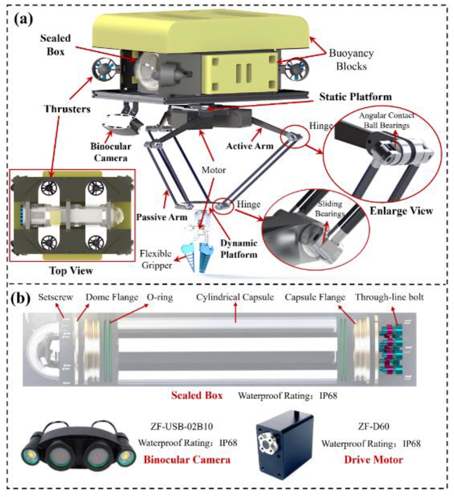
Figure 2.
(a) Control system framework and key equipment of the proposed UVMS and (b) control strategy of the proposed UVMS.
Figure 2.
(a) Control system framework and key equipment of the proposed UVMS and (b) control strategy of the proposed UVMS.
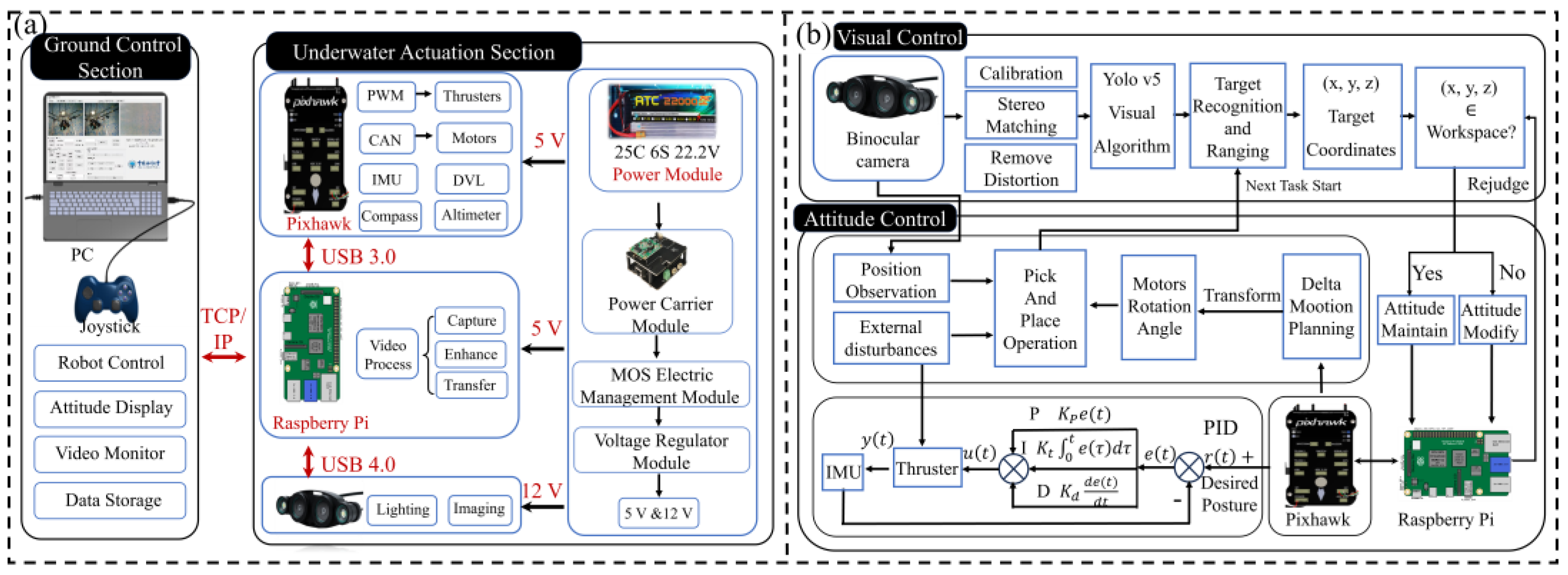
Figure 3.
The control block diagram for target capture.
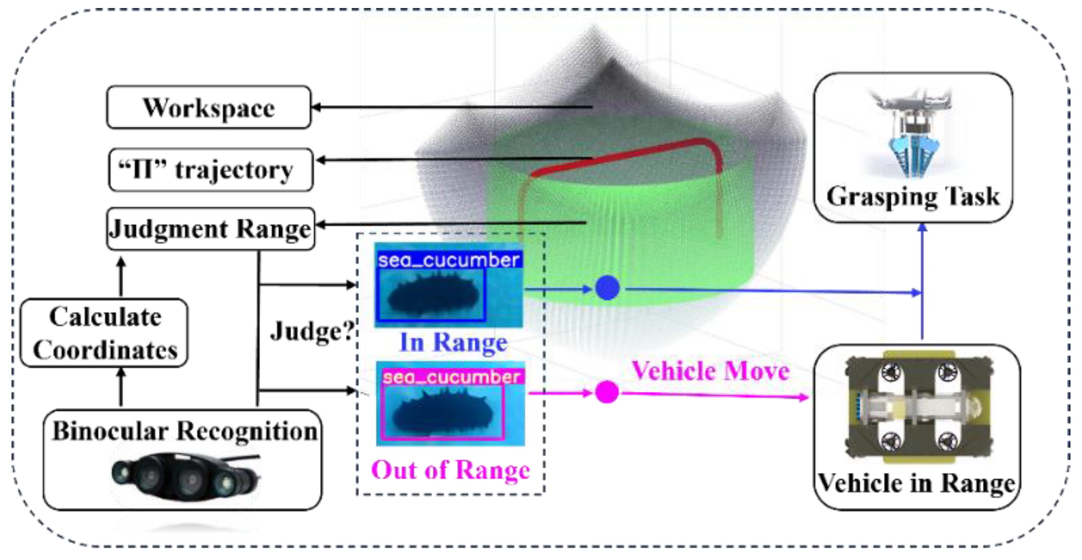
Figure 4.
Mechanism sketch of the proposed UVMS.
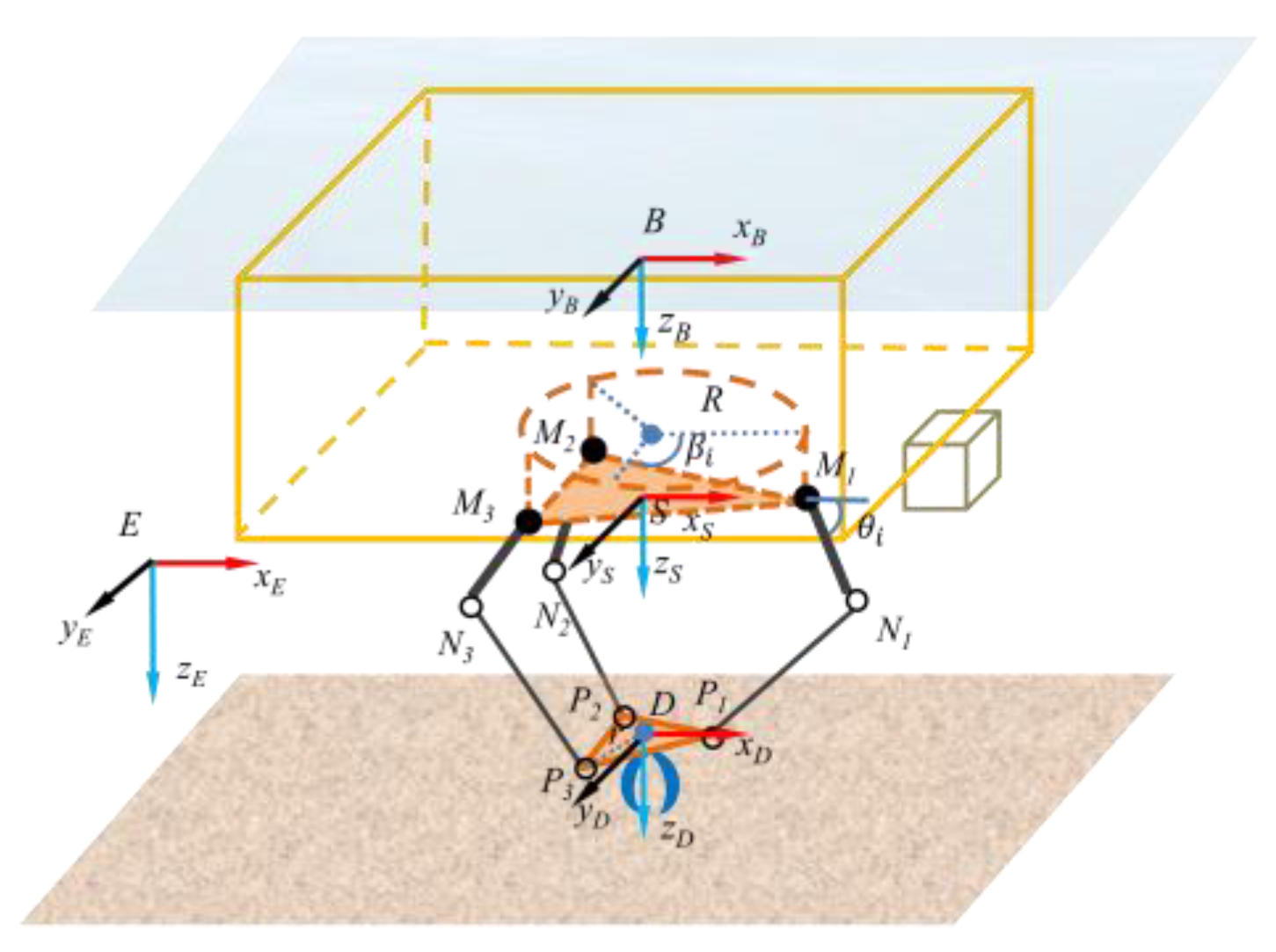
Figure 5.
(a) The simulation model configurations for Delta and Serial UVMS types, (b) end-effector executing identical predefined "∩" and "∞" trajectories, the corresponding simulation results about Force and Torque variation in x, y, z directions of (c) "∩" and (d) "ꝏ".
Figure 5.
(a) The simulation model configurations for Delta and Serial UVMS types, (b) end-effector executing identical predefined "∩" and "∞" trajectories, the corresponding simulation results about Force and Torque variation in x, y, z directions of (c) "∩" and (d) "ꝏ".
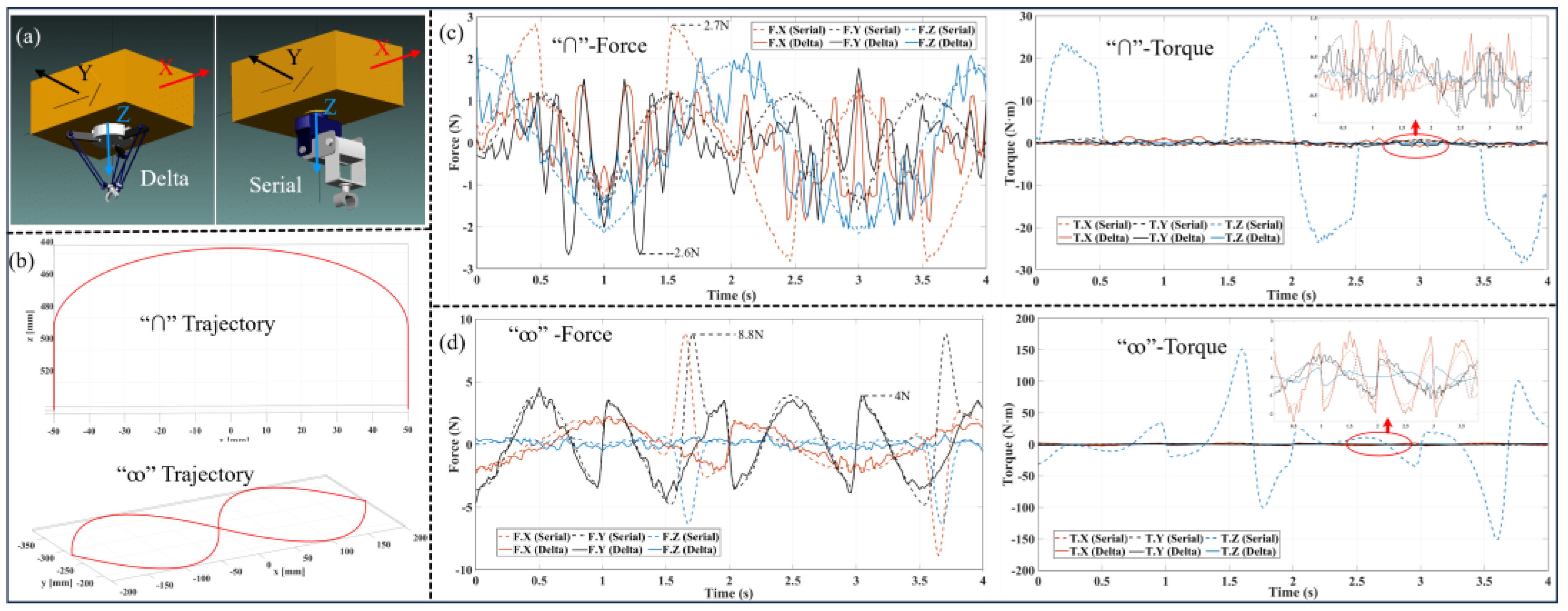
Figure 6.
Trajectory tracking performance of the end-effector for Delta parallel UVMS and serial UVMS, showing (a) "∩" trajectory, and (b)."∞"trajectory.
Figure 6.
Trajectory tracking performance of the end-effector for Delta parallel UVMS and serial UVMS, showing (a) "∩" trajectory, and (b)."∞"trajectory.
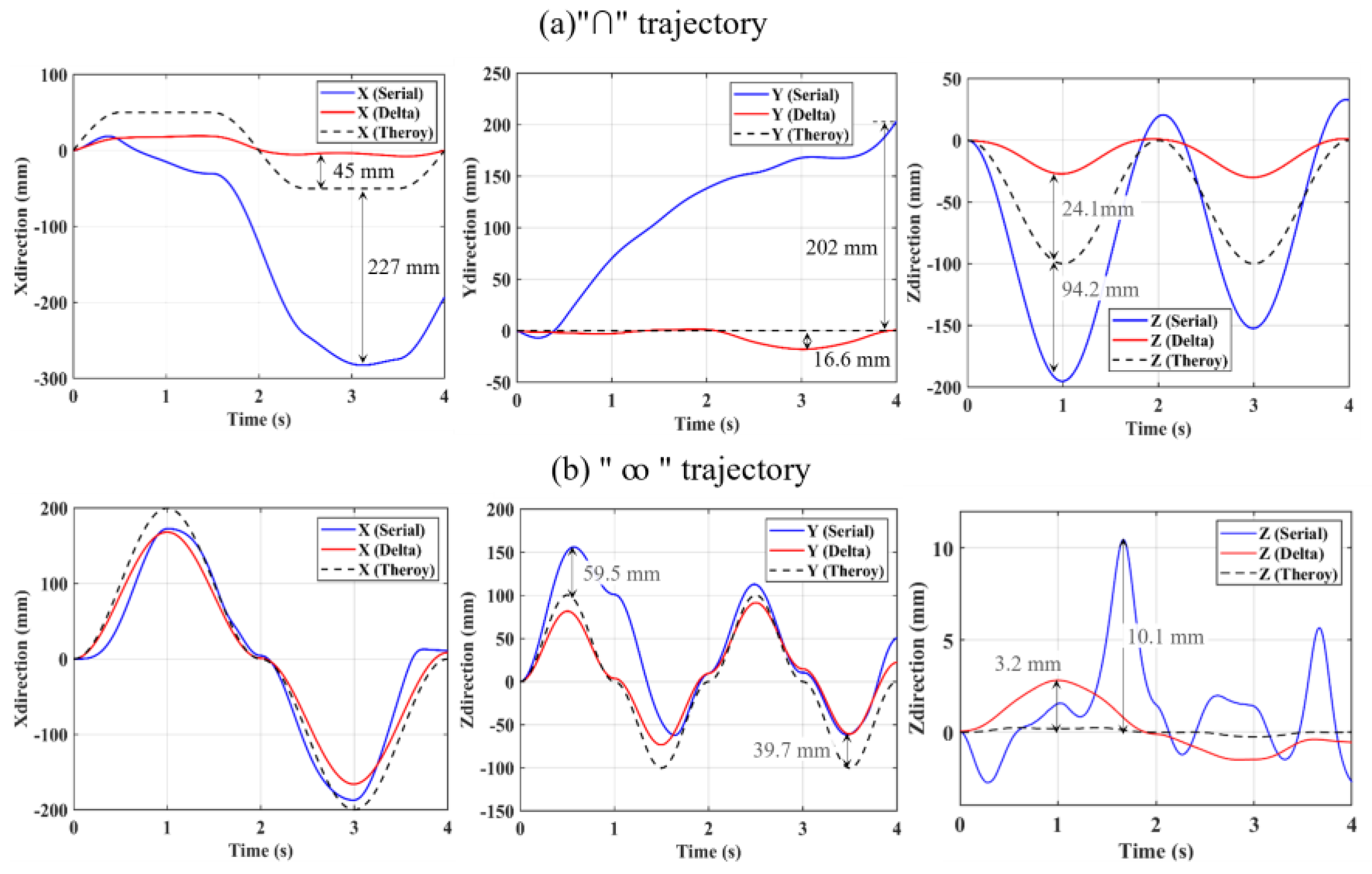
Figure 7.
Mechanical performance of the Delta gripper unit, showing (a) experimental setup for evaluating kinematic accuracy of the fabricated Delta robot, (b) sea cucumber model grasping experiment, (c) “∩” Shape motion trajectory of the Delta robot, (d) “ꝏ” shape motion trajectory of the Delta robot.
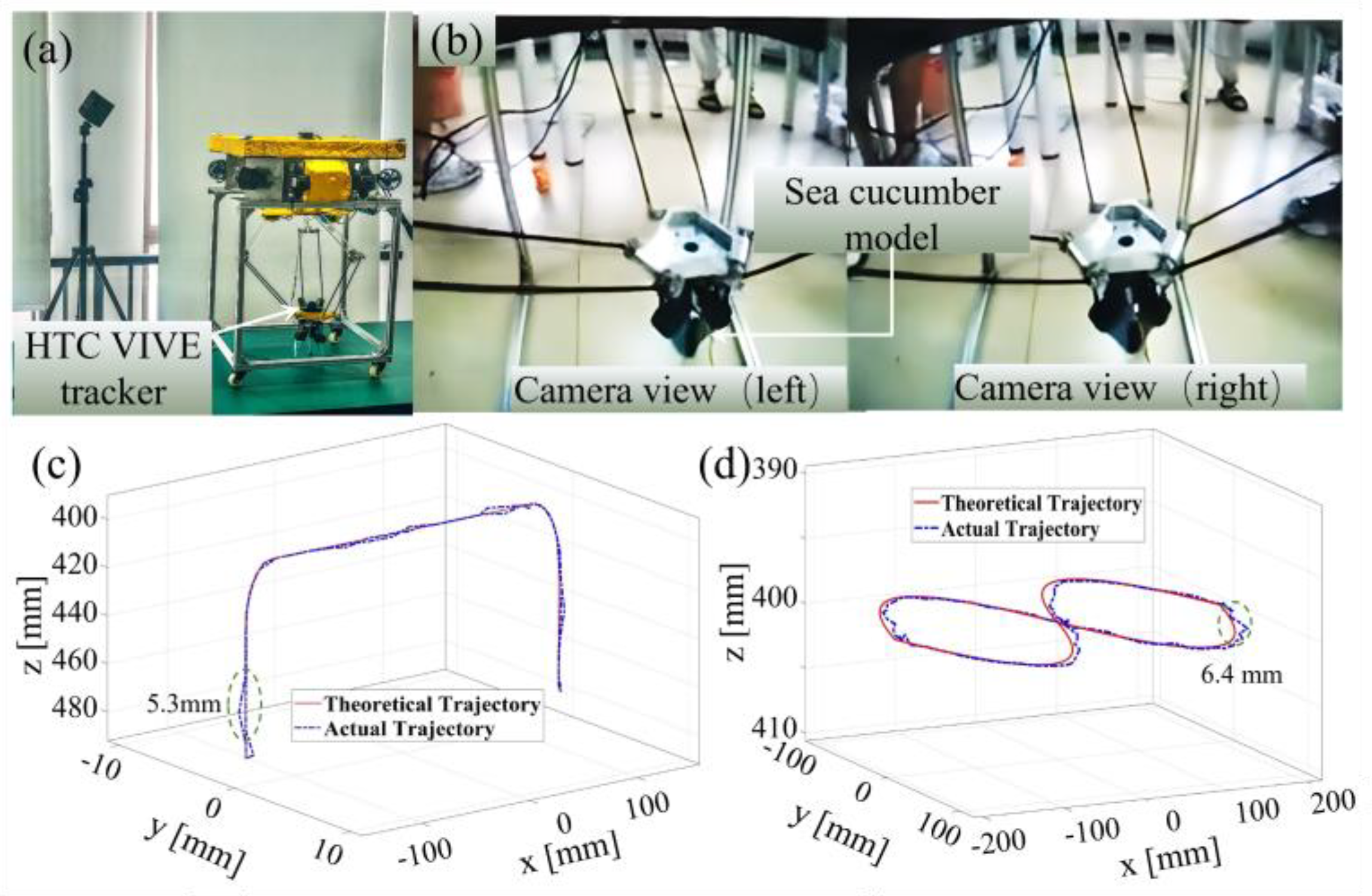
Figure 8.
(a) the kinematic performances of the floating-motion unit, (b) experimental setup for the stationary UVMS, (c) experimental setup for the floating UVMS, (d) angular information measured by the angle sensors mounted on the vehicle body.
Figure 8.
(a) the kinematic performances of the floating-motion unit, (b) experimental setup for the stationary UVMS, (c) experimental setup for the floating UVMS, (d) angular information measured by the angle sensors mounted on the vehicle body.
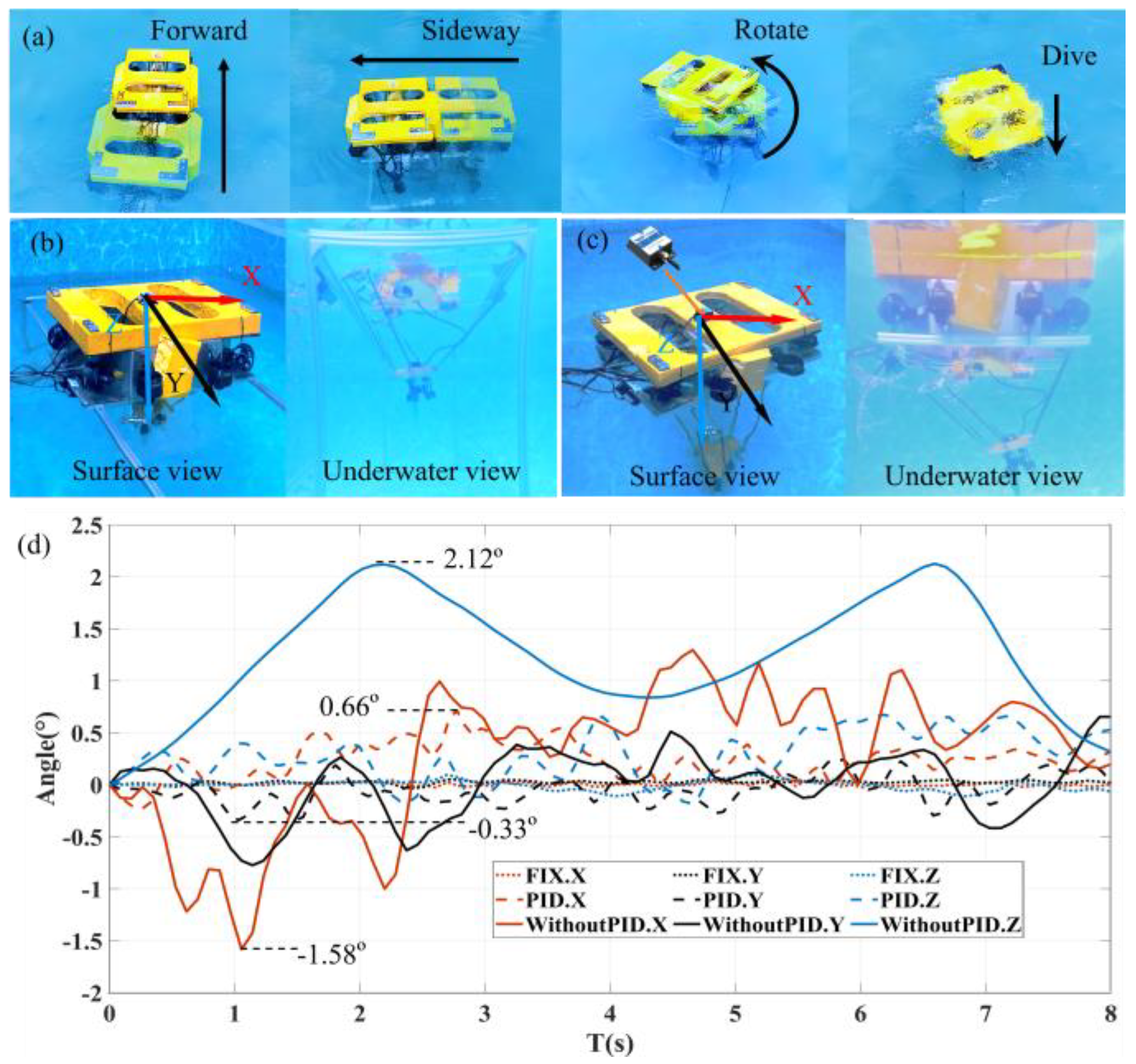
Figure 9.
Underwater grasping experiment of a sea cucumber model, showing (a) the experimental setup, (b) image recognition and boundary region determination using binocular camera, (c) grasping process for the sea cucumber model, (d) transfer process for the sea cucumber model, (e) transfer process for the steel pipe.
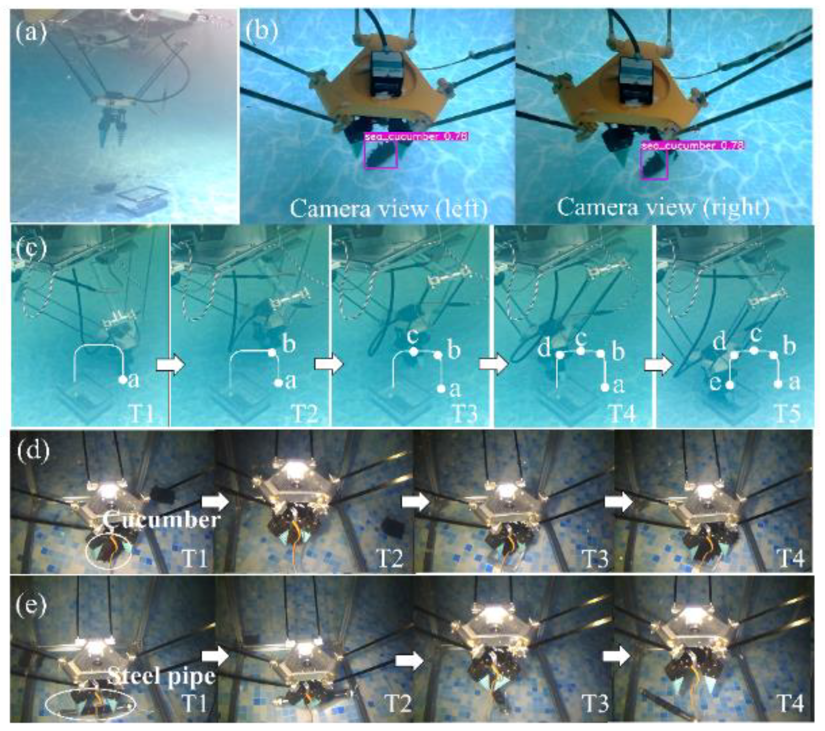
Table 1.
Parameters of the umbilical cable.
| Parameters | Norm | Note |
| Working depth (m) | 300 | Maximum design water depth |
| Weights (kg) | ≤30 | Dry weight |
| Overall size (mm) | 550×400×700 | L×W×H |
| Rating (kW) | 2 | Battery Output |
| Maximum thrust (kg) | 8 | - |
| Robotic Load (kg) | 25 | Catch Max |
| Robotic servo torque (Nm) | 2 | - |
| Duration (min) | ≥30 | Battery-powered |
| Battery capacity (mAh) | 16000 | Rechargeable |
| Number of camera paths | 2 | Monocular +Binocular |
| Remote operation mode | PC + Joystick | - |
Disclaimer/Publisher’s Note: The statements, opinions and data contained in all publications are solely those of the individual author(s) and contributor(s) and not of MDPI and/or the editor(s). MDPI and/or the editor(s) disclaim responsibility for any injury to people or property resulting from any ideas, methods, instructions or products referred to in the content. |
© 2025 by the authors. Licensee MDPI, Basel, Switzerland. This article is an open access article distributed under the terms and conditions of the Creative Commons Attribution (CC BY) license (http://creativecommons.org/licenses/by/4.0/).
Copyright: This open access article is published under a Creative Commons CC BY 4.0 license, which permit the free download, distribution, and reuse, provided that the author and preprint are cited in any reuse.


