Submitted:
17 November 2025
Posted:
18 November 2025
You are already at the latest version
Abstract
Clearances in robot kinematic joints, which are functionally required, can have a significant influence on dynamic behavior and on optimal design, implicitly. Consequently, this paper aims to highlight the influence of clearances in the upper and lower spherical joints of a Delta parallel robot on trajectory accuracy and motor torques, under dynamic conditions with high speeds and accelerations. The employed method involves CAD modeling of the Delta robot's mechanical system in CATIA software and simulating its dynamic behavior in ADAMS software, using a representative trajectory where the end-effector's speed and acceleration reach the robot maximum admissible values. Considering different clearance values and various scenarios (clearances only in the upper spherical joints, only in the lower ones, and cumulatively), the simulation results highlighted a major kinematic and dynamic influence of the clearances from the upper spherical joints (with errors up to 0.05% for speeds, 0.06% for accelerations, and up to 0.19% for torques) and a relatively insignificant influence of those in the lower joints (with errors up to 0.00018% for speeds, 0.00041% for accelerations, and up to 0.172% for torques). The cumulative effect of these clearances was also analyzed, concluding that a little non-linear coupling impact was identified.
Keywords:
Delta parallel robot
; spherical joint clearance
; dynamics
; trajectory errors
; torque errors
; CAD model
; ADAMS simulation
1. Introduction
Parallel robots offer several advantages (such as high speed and precision, high rigidity at low mass, higher payload capacity, etc.) compared to serial robots, due to the interconnection of the end-effector to the fixed platform by two or more parallel-mounted arms. Among the parallel robots available on the market, the 3-degrees-of-freedom (3-DOF) Delta robot is one of the most widely used in industrial applications, especially for “pick-and-place” tasks (assembly, packaging, etc.), which often require dynamic stability, high operating speeds, and high accelerations, along with high accuracy.
The Delta parallel robot, patented by Reymond Clavel in 1987 [1], has a mobile platform connected to a fixed base by three articulated arms. This design includes a 3-DOF end-effector capable of performing linear movements in three-dimensional (3D) space.
The Delta parallel robot is renowned for its high speed and acceleration, making it ideal for applications that require fast and precise movements. Numerous studies have explored various aspects of this robot, including analytical modeling (kinematics and dynamics), CAD modeling and simulation, as well as analyses regarding the effect of joint clearances or element elasticities. Clearances in the joints are inevitable in the construction of any mobile mechanical system because of manufacturing tolerances and inherent assembly imperfections. These clearances negatively affect dynamic performance, reduce component lifespan, and generate unwanted vibrations due to the impact of contacting parts [2].
The trajectory tracking accuracy (position, speed, and acceleration errors of the end-effector) and motor torques can be significantly affected due to inertial effects on flexible elements and the existence of joint clearances. Cretescu et al. [2] conducted a study of a Delta robot in various scenarios: considering in turn the natural flexibility of the compliant elements, the clearance and friction in the spherical joints, as well as their cumulative effect. The paper concluded that the dynamic effect of these parameters is not additive, while significant reciprocal influences were identified.
Several other studies [3,4,5] addressed the influence of clearances in kinematic joints on the kinematic and dynamic behavior or the positioning accuracy in the workspace of 3-DOF Delta parallel robots, the results being applicable to other parallel mechanisms. Thus, an elastic model of the Delta parallel robot was proposed by Zheng and Zhang [5] exploiting the finite element method and Lagrange equations, which also includes the effect of clearance. The study provided a basis for error compensation and vibration reduction in industrial parallel robots. Ohno and Takeda [6] analyzed the clearances that occur due to wear in the passive joints of a Delta parallel robot. The method utilizes a linearized model that correlates the clearance with the actuation torque difference, introducing stochastic variables. The experiments, performed on an industrial Delta robot with spherical joints having clearances between 0 and 0.15 mm, demonstrated the feasibility of fault detection by this method, validated through a stochastic evaluation of the clearance estimation performance. The same authors proposed another method to detect excessive clearances in the passive joints of parallel robots, tested on a Delta robot [7]. Based on torque fluctuations on predefined trajectories, the proposed method allowed correct detection rates (true positives) of over 80% and error rates (false positives) under 10%.
A method for direct calculation of positioning errors, caused by clearances in passive spherical joints of parallel mechanisms, eliminating the need for numerical integration or iterations, was proposed and investigated by Ohno and Takeda [8]. A model for spherical joints was proposed, defining the relationship between relative displacement and joint force, initially ignoring the clearance. Based on the principle of virtual work, a procedure was developed to determine the positioning errors resulting from clearances. Experiments performed on a Delta parallel robot validated the method, the calculated position errors being in concordance with the experimental ones.
Based on Hertz elastic theory, a study regarding the kinematic and dynamic behavior of a 3RRR planar parallel robot, when clearances in the 6 revolute joints were taken into consideration, is presented in [9]. The dynamic behavior of a planar mechanism was investigated considering clearances, using a continuous contact force model, based on Hertz elastic theory along with a dissipative term.
Dynamic models of robots with parallel [10,11,12] or hybrid [13] mechanisms, which also include joint clearances, have been developed applying the modified Flores and Columb contact model. Numerical simulations explore the dynamic effects of clearances and load on robot orientation accuracy, concluding that larger clearances and higher load reduce accuracy, while smaller clearances and higher loads lead to a better stability of motion.
Another approach frequently employed in dynamic modeling is the Newton-Euler (N-E) method. Thus, such N-E models applied to parallel mechanisms are presented in [14,15,16], numerical simulations showing that impact and friction forces lead to irregular wear in the spherical joint, and prolonged wear amplifies contact force fluctuations and reduces the motion stability of the mechanism. The results show that irregular clearance (due to wear) significantly amplifies vibrations and contact force, compared to regular clearance. Hysteresis is also observed in the displacement, speed, and acceleration curves. Thus, irregular clearances caused by wear deteriorate the mechanism’s performance, intensifying wear and reducing its stability and reliability.
The Lagrange multipliers method was also utilized in dynamic studies of parallel mechanisms, planar [17] or spatial [18], including clearances in the spherical joints. Chen and Guo [17] indicated that a single clearance has a minimal impact on dynamic characteristics, which remain close to ideal values. Mojtaba Varedi Koulaei et al. [18] showed that the optimal design of clearances significantly reduces linear and angular accelerations, as well as contact forces, ensuring a smooth evolution of motion. The validity of the algorithm was confirmed by comparative simulations in ADAMS software.
The design and analysis of a multidimensional vibration isolator for protecting precise equipment mounted on vehicles, with a design based on a parallel mechanism with joint clearances, was addressed by Gao et al. [19]. The main goal was to establish the kinematic and dynamic equations of the isolator and to evaluate its vibration isolation capacity in the presence of clearances. The results demonstrated the isolator’s efficiency in reducing multidimensional vibrations but also showed the sensitivity of the first-order resonance peak to the increase of clearances.
Using the Multi Body Systems (MBS) method, Xu et al. [20] proposed a methodology for the analysis of dynamic response and system consistency with multiple revolute clearance joints. An improved impact force model and a modified friction force model were employe for modeling the impact and friction in these joints. The results demonstrated that clearances have a minimal impact on displacement and angular velocity but significantly influence angular acceleration.
Yu and Tian [21] proposed and investigated a method for compensating the position errors of parallel robots, caused by joint clearances. Thus, a joint error model was developed for a 3-RRR planar parallel robot and the impact of clearances on link lengths and angular displacements were analyzed. The trajectory errors of the end-effector were reduced by 99% compared to the uncompensated trajectory, validating the method’s efficiency in compensating for structural errors and ensuring the position accuracy of the parallel robot.
The study presented by Xin et al. [22] introduced an actuation acceleration-based kinematic modeling and identification method for 6-PSU (Prismatic-Spherical-Universal joints) robots with clearances. The clearance direction was correlated with the force applied to the joint, determined by the acceleration of the prismatic actuators. The clearances were modeled as variations of link lengths, experimentally identified and compensated, and the simulations and experiments validated the method’s efficiency, demonstrating an improvement in the accuracy of the kinematic model.
An elastodynamic model of kinematic chains, using spatial beam elements and kineto-elastodynamic theory was developed by Guo et al. [23]. The model aimed to obtain rigid-flexible dynamic behavior of a hybrid parallel robot utilized for the precise polishing of aspherical optical mirrors, combining a serial-parallel manipulator with a two-rotor grinding system. Thus, the dynamic effect of joint clearances was introduced into the model and the load distribution and the impact of chain elasticity and clearances on motion errors were analyzed.
Dynamic analysis, with an emphasis on the impact of joint clearances, was addressed by Chen et al. [24] in the case of a new type of spatial parallel robot, for which a virtual prototype was created in Adams. Numerical simulations allowed obtaining the kinematic response and contact forces, concluding that clearances and friction significantly influence the robot’s dynamics (assuming rigid bodies).
Zhang et al. [25] analyzed the impact of joint clearances on the precision and efficiency of a 2-DOF planar parallel robot, utilized in high-speed and high-precision packaging equipment. The simulations demonstrated that the size of the clearances directly affects the packaging precision and speed, offering a reference point for the design and selection of packaging equipment.
The paper proposes an analysis utilizing ADAMS software regarding the effect of spherical joint clearances on the kinematic and dynamic behavior of a Delta parallel robot. This work aims to analyze the dynamic impact of clearances in all spherical joints (upper and lower), considered both separately and combined. Also, various values of spherical joint clearances were taken into consideration, to establish the correlation between the value of clearances and trajectory accuracy corroborated with motor torque errors.
2. Problem Formulation
The dynamic effect analysis of joint clearances, addressed in this paper, focuses on the SIAX D3 1600 Delta parallel robot [26], available on the market for various industrial applications.
The effect of clearances from the Delta robot spherical joints can be studied numerically by developing, in the first stage, a CAD model in a 3D modeling software, such as CATIA, followed in the second stage by ADAMS simulation. Because ADAMS does not easily allow the creation of elements with complex geometric shapes, a 3D CAD model in CATIA became a useful option, followed by exporting the 3D bodies (in IGES format) and importing them into ADAMS. Thus, an accurate CAD model can be obtained in ADAMS that reflects closely the existing physical robot [2].
The Siax D3-1600 Delta robot (Figure 1) is a 3-DOF parallel robot, the end-effector being constrained only to spatial translation movements, without changing orientation. It is composed by a fixed platform (0) and a mobile platform (4), interconnected by three arms (A, B, and C), each of which is provided with an actuation element (1) connected to the base by a motor revolute joint (R) [2]. The three arms are equiangularly distributed in relation to the global coordinate system (X0Y0Z0) of the robot, with the origin at point O—the center of the fixed platform in the upper plane. The Delta robot has a payload attached to the end-effector in the shape of a cylinder with a mass of 5 kg (the maximum admissible load). The characteristic point P is the origin of the end-effector’s mobile coordinate system and follows a spatial trajectory established to reach the maximum admissible speed and acceleration. The robot has a total mass of 80 kg [26].
The arm lengths of the robot have values of 500 mm for l1 and 1106 mm for l2 and l3 (Figure 1.a), the three arms (A, B, and C) being arranged at 120∘ (Figure 1.b). The rods l2 and l3 are organized on each arm in the configuration of a parallelogram kinematic chain.
The geometric and mass properties of the Delta robot’s component elements, as key factors in determining its dynamic behavior, are systematized in Table 1.
In the proposed analysis, the following assumptions are considered:
- ✓ The links are rigid solid bodies;
- ✓ All elements are made of steel;
- ✓ The clearances in the spherical joints (distance between the centers of the component spheres) have discrete values between 0.1 mm and 0.6 mm, with a step of 0.1 mm (i.e., six cases) in three scenarios: a) clearances only in the upper spherical joints; b) only in the lower ones; c) the combined variant a)+b).
3. Results and Discussions
The starting point (P0) of the Cartesian trajectory corresponds to the robot’s initial position where all three active motor joints (RA, RB, and RC) are in the zero position, and the motor elements are arranged in the same horizontal plane (parallel to X0Y0), Figure 2. The trajectory P0P1 is a spatial curve obtained by applying an angular displacement of 25° in joint RA, −70° in joint RB, and −60° in joint RC (Figure 3a). Along this trajectory, the maximum values of linear speed (8 m/s) and acceleration (120 m/s2) are reached, which are ensured by commanding angular speeds of 242°/s in RA, 554°/s in RB, and 656°/s in RC (Figure 3b), as well as angular accelerations of 3003°/s2 (RA), 8824°/s2 (RB), and 4123°/s2 (RC), as shown in Figure 3c.
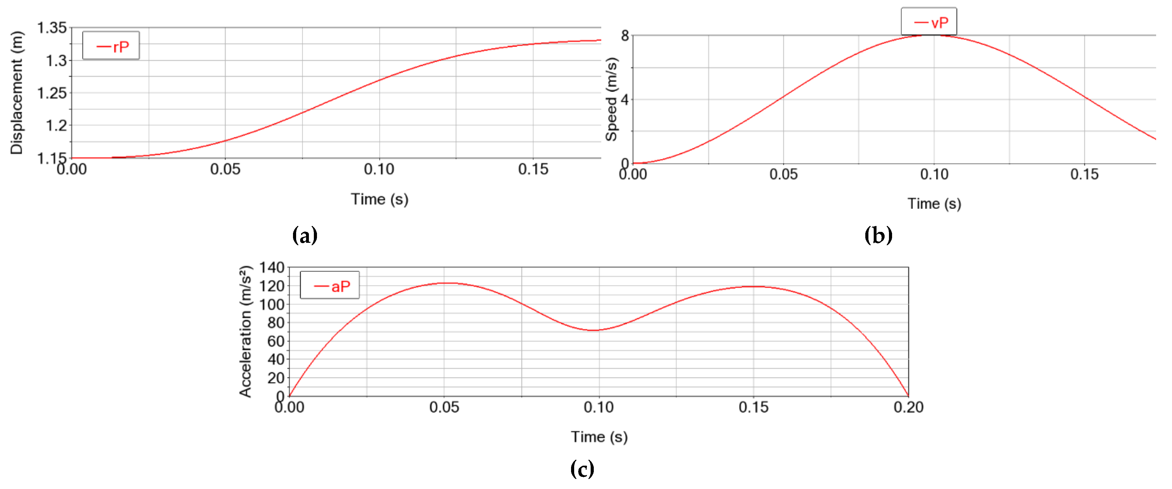
The Cartesian trajectory P0P1 (Figure 2) is obtained by applying a fifth-degree polynomial motion trajectories in the active joints. This trajectory is characterized by the movement of the characteristic point P along all three axes of the global coordinate system X0Y0Z0 (Fig. 4) and it reaches a final position rP = 1.245 m (Figure 5a). Also, the point P reaches the maximum speed vPmax = 8 m/s at 0.1 s (Figure 5b) and the maximum acceleration aPmax = 120 m/s2 at approximately 0.052 s and 0.158 s (Figure 5c).
Figure 4.
The end-effector’s displacement projected onto the axes of the global coordinate system O0X0Y0Z0.
Figure 4.
The end-effector’s displacement projected onto the axes of the global coordinate system O0X0Y0Z0.
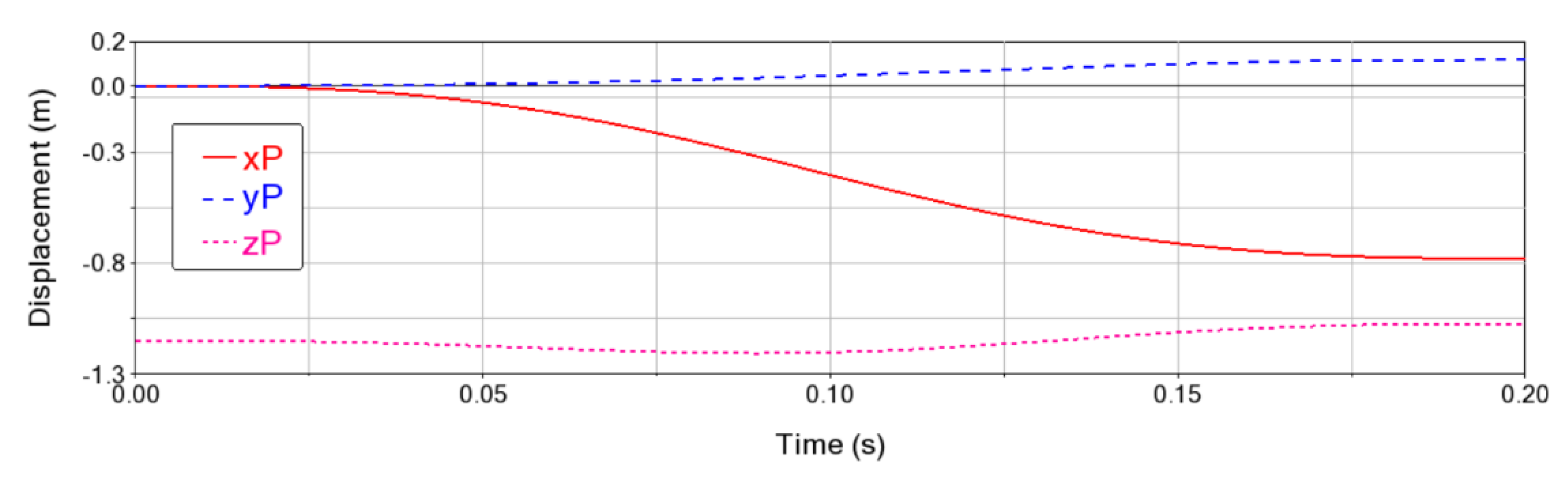
Figure 5.
The motion of the Delta parallel robot end-effector: (a) displacement; (b) speed and (c) acceleration.
Figure 5.
The motion of the Delta parallel robot end-effector: (a) displacement; (b) speed and (c) acceleration.
The torques in the active joints along the mentioned trajectory (Figure 6) have a profile like the angular acceleration (see Figure 3c); higher values are observed for torques TA and TB (up to 898 N⋅m) due to higher angular accelerations (and consequently higher angular speeds and displacements) compared to torque TC (up to 358 N⋅m).
The dynamic influence of the spherical joint clearances is analyzed considering the set of values Δr = [0.1, 0.2, 0.3, 0.4, 0.5, 0.6] mm, defined as the distance between the centers of the spheres (O1 and O2) (Figure 7).
Next, the numerical results obtained in three scenarios are presented and discussed: clearances only in the upper joints (&3.1), only in the lower ones (&3.2) and in both categories of spherical joints (&3.3).
3.1. Analysis of the Kinematic and Dynamic Errors of the Delta Parallel Robot with Clearances in the Upper Spherical Joints
The first case considers clearances in the upper spherical joints, analyzing the influence of clearances in the upper spherical joints, with values between 0.1 mm and 0.6 mm, on the kinematic and dynamic behavior of the Delta parallel robot.
For Δr = [0.1, 0.6] mm in the upper spherical joints, the errors on the end-effector trajectory record values of up to 0.0147 mm for displacements, up to 4.744 mm/s for speeds, and 79.204 mm/s2 for accelerations (Figure 8 and Table 2).
As depicted in Figure 8, an increase in trajectory errors can be observed as the clearance increases, but the variation shape is maintained.
In addition to the resultant errors in 3D space, graphically represented in Figure 8, the components of these errors along the three axes (X, Y, and Z) are further analyzed for displacements (Figure 9), speeds (Figure 10), and accelerations (Figure 11). Thus, it can be remarked that errors are recorded on all three axes: a) they start from 0 for the X and Y axes, and have a value equal to the clearance for the Z axis; b) the errors increase as the clearances increase; c) the errors change over time (increase/decrease) following shapes similar to those recorded by the movement of the characteristic point P: as the absolute values of the kinematic parameters increase, the errors of these parameters also increase.
The motor torques are influenced by the clearances in the upper spherical joints, which record increasing errors as the joint clearance increases, up to 0.16% as can be observed in Figure 12 and Table 3. In conclusion, the motor torque errors tend to increase in absolute value as the clearances increase, with an approximately linear dependence on the clearances in the motor joints.
3.2. Analysis of the Kinematic and Dynamic Errors of the Delta Parallel Robot with Clearances in the Lower Spherical Joints
Like the approach in section 3.1, the influence of the clearance in the lower spherical joints of the Delta parallel robot is analyzed, assuming zero clearance in the upper spherical joints and considering the same set of clearance values of 0.1 mm, 0.2 mm, 0.3 mm, 0.4 mm, 0.5 mm and 0.6 mm.
The numerical simulation results reveal a quasi-constant displacement error of the characteristic point P, which does not exceed the initial clearance value (Figure 13a), the end-effector trajectory in this case being practically parallel to the commanded one at a quasi-constant distance along the z axis equal to the clearance (Figure 14). The speed and acceleration errors (Figure 13b and c) increase as the clearance increases, with a curve profile similar to the error curves, but are significantly smaller than in the case of clearances in the upper joints (∼300 times smaller for speeds and ∼150 times smaller for accelerations, see Table 4 vs Table 2).
The torque errors (Figure 15) have relatively small values, up to a maximum of ∼1.47 N⋅mm for active joint RB, which practically generate insignificant variations in motor torques (max. 0.000163%). The effect of increasing torque errors as the clearance in the lower joints increases remains valid in this case as well, with maximum values of ∼0.45 N⋅mm for TA, ∼1.47 N⋅mm for TB, and ∼0.98 N⋅mm for TC (for 0.6 mm clearances, see Table 5).
3.3. Analysis of the Kinematic and Dynamic Errors of the Delta Parallel Robot with Clearances in the Upper and Lower Spherical Joints
In this scenario, the cumulative case of clearances in both the upper and lower spherical joints is considered, with values in the interval [0.1, 0.6] mm, considering identical values in all spherical joints of the Delta robot.
Thus, the displacement errors of the characteristic point P (Figure 16a) record double the clearance value at the beginning of the trajectory, because of the accumulation of clearances from upper and lower spherical joints. These initial values slightly reduce along with the trajectory, with deviations smaller than ∼0.11 mm (in the case of 0.6 mm clearance, Table 6). The maximum values of the displacement errors (Table 6) increase as the clearance in the spherical joints increases, with the impact of the clearance in the upper spherical joints being predominant.
The speed error of the characteristic point P (Figure 16b) has a curve profile like the one obtained in the case of clearances in the upper joints (Section 3.1), reaching a maximum of ∼4.75 mm/s for the 0.6 mm clearance case. Similarly, the acceleration errors on the trajectory (Figure 16c) increase as the joint clearance increases, reaching a maximum of ∼79 mm/s2 (for the 0.6 mm clearance).
The motor torque errors in this scenario are presented in Figure 17, and the maximum values in Table 7. Thus, a maximum value of ∼1549 N⋅mm is reached in motor joint RA, for the 0.6 mm clearance. Since the major contribution is due to clearances in the upper joints, the shape of the torque error curves is similar to that presented in Section 3.1, Figure 12.
As can be observed from both Figure 17 (time evolution of errors) and Table 7 (maximum values), the torque errors increase as the clearances increase, with amplitude variations that progressively increase with the value of the clearance in the Delta robot’s spherical joints.
As with motion errors, the dynamic behavior is predominantly influenced by the clearances in the upper spherical joints, the influence of clearances in the lower joints being practically insignificant. For this reason, the non-linear coupling effect of clearances in the upper spherical joints with those in the lower ones is diminished to negligible values. Thus, the kinematic and dynamic errors in this case of combining clearances from all spherical joints can be acceptably approximated by the sum of the errors obtained in the scenarios from Section 3.1 and, respectively, Section 3.2.
4. Conclusions
Starting from the case study of the SIAX D3 1600 Delta parallel robot, this paper analyzed the impact of spherical joint clearances on the kinematic and dynamic behavior of the robot on a test spatial trajectory, through numerical simulation in ADAMS software. For this purpose, a variation range of spherical joint clearances in the interval [0.1,…,0.6] mm was considered, examining three scenarios: (a) identical clearances only in the upper spherical joints (Section 3.1); (b) identical clearances only in the lower spherical joints (Section 3.2); (c) the same clearances in all spherical joints (upper and lower, Section 3.3). The results obtained allowed us to draw the following conclusions:
- Clearances in the upper spherical joints generate a geometric deviation of the characteristic point from the commanded trajectory approximately equal to the clearance value and influence the speed and acceleration on the trajectory (maximum errors of up to 0.06%−0.07%). Similarly, motor torques record errors of up to ∼0.17% for active joint RA and ∼0.08% for joints RB and RC.
- Clearances in the lower spherical joints have a significant effect on the displacement accuracy of the characteristic point (geometric errors equal to the clearance). However, the generated kinematic errors are negligible (max. 0.000183% for speeds and 0.000409% for accelerations); similarly, the motor torque errors can be considered practically insignificant (maximum errors of ∼0.000163%).
- The errors in speed, acceleration, and motor torques are in direct dependence on the values of these parameters, and the maximum error values increase approximately linearly with the increase of the joint clearance.
- Clearances in the upper spherical joints have a distinctly superior impact to lower joint clearances; consequently, in Scenario (c) of considering clearance in all spherical joints of the robot, results were obtained very close to those resulting from Scenario (a).
- Consequently, in the design process of the Delta parallel robot, greater attention must be paid to clearances in the upper spherical joints compared to the lower ones: the geometric errors on the trajectory are similar, but the errors generated for speeds, accelerations, and motor torques are significantly higher.
As a future development, the authors propose to analyze the cumulative effect of combinations of error factors, such as kinematic errors from motor joints, flexibility of compliant elements, and clearances in the Delta robot’s joints, as well as the experimental validation of the numerical results.
Author Contributions
Conceptualization, M.N. and N.C.; methodology, M.N. and N.C.; software, N.C.; validation, M.N.; formal analysis, M.N. and N.C.; investigation, M.N.; resources, N.C.; data curation, M.N.; writing—original draft preparation, N.C.; writing—review and editing, M.N.; visualization, M.N. and N.C.; supervision, M.N. All authors have read and agreed to the published version of the manuscript.
Institutional Review Board Statement
Not applicable.
Informed Consent Statement
Not applicable.
Data Availability Statement
Not applicable.
Conflicts of Interest
The authors declare no conflicts of interest.
References
- Clavel R. Dispositif pour le déplacement et le positionnement d’un élément dans l’espace, Google Patents (WO1987003528A1), 1987.
- N. Cretescu, M. Neagoe, R. Saulescu, Dynamic Analysis of a Delta Parallel Robot with Flexible Links and Joint Clearances, Applied Sciences 13(11), 2023, 6693.
- Andrioaia, Dragos & Stan, Gheorghe & Funaru, Marian & Obreja, Claudiu. The Influence of Kinematic Joints Clearances on the Positioning Accuracy of 3DOF Delta Parallel Robots. Applied Mechanics and Materials. 371, pp. 406-410. 2013. 10.4028/www.scientific.net/AMM.371.406.
- Shehata, Mohamed & Elshami, Mohamed & Bai, Qing-Shun & Zhao, X., Parameter Estimation for Multibody System Dynamic Model of Delta Robot From Experimental Data. IFAC-PapersOnLine, 2021, 54. 72-77. 10.1016/j.ifacol.2021.10.331.
- Zheng, K. & Zhang, Q. Elastic dynamics and analysis of vibration characteristics of Delta robot with joint clearance. Nongye Gongcheng Xuebao/Transactions of the Chinese Society of Agricultural Engineering. 2015. 31. 39-48. [CrossRef]
- Ohno, Masumi & Takeda, Yukio. Model Based Estimation of Passive Joint Clearance in Parallel Robot and Its Application to Failure Detection. Proceedings of I4SDG Workshop 2021, IFToMM for Sustainable Development Goals. pp.362-371. [CrossRef]
- Ohno, Masumi & Takeda, Yukio. Trajectory Design Based on Joint Impact Index for Detecting Joint Clearance in Parallel Robot. Advances in Mechanism and Machine Science. 2019. pp.2017-2025. [CrossRef]
- Ohno, Masumi & Takeda, Yukio. Efficient computation of motion error of parallel robots with joint clearances based on joint force model. Transactions of the JSME (in Japanese). 2018. 84. [CrossRef]
- Varedi-Koulaei SM, Daniali HM, Farajtabar M. The effects of joint clearance on the dynamics of the 3RRR planar parallel manipulator. Robotica. 2016 ;35(6):1223-1242. [CrossRef]
- Sun, Jing & Song, Jingwei & Wang, Yongjie. Dynamic modeling and analysis of 3-RRCPR parallel pointing mechanism with clearance. Transactions on Engineering and Technology Research. 2024. 2. doi: 188-202. 10.62051/nsfsc329.
- Sun, Jing & Song, Jingwei & Wang, Yongjie. Dynamic modeling and analysis of 3-RRCPR parallel pointing mechanism with clearance. Transactions on Engineering and Technology Research. 2024. 2. 188-202. [CrossRef]
- Wang, Gengxiang. Dynamics Analysis of 4-SPS/CU Parallel Mechanism with Spherical Joint Clearance. Journal of Mechanical Engineering. 2015. 51. [CrossRef]
- Xin, Yuechuan & Zhu, Jianuo & Meng, Kai & Jiang, Shuai. Nonlinear dynamics study of hybrid mechanism considering three-dimensional revolute joint clearance. Nonlinear Dynamics. 2025. 1-31. [CrossRef]
- Chen, Xiulong & Li, Yuewen. Dynamics Analysis of Spatial Parallel Mechanism with Irregular Spherical Joint Clearance. Shock and Vibration. 2019. 1-21. [CrossRef]
- Hou, Yu-lei & Deng, Yun-jiao & Zeng, Da-xing. Dynamic modelling and properties analysis of 3RSR parallel mechanism considering spherical joint clearance and wear. Journal of Central South University. 2021. 28. 712-727. [CrossRef]
- Chen, Xiulong & Li, Yuewen. Dynamics Analysis of Spatial Parallel Mechanism with Irregular Spherical Joint Clearance. Shock and Vibration. 2019. 1-21. [CrossRef]
- Chen, Xiulong & Guo, Jingyao. Effects of Spherical Clearance Joint on Dynamics of Redundant Driving Spatial Parallel Mechanism. Robotica. 2020. 39. 1-17. [CrossRef]
- Varedi Koulaei, Seyyed Mojtaba & Daniali, Hamid & Farajtabar, M. & Fathi, B. & Shafiee, Milad. Reducing the undesirable effects of joints clearance on the behavior of the planar 3-RRR parallel manipulators. Nonlinear Dynamics. 2016. 86. [CrossRef]
- Gao, Xiang & Niu, Junchuan & He, Lei & Qin, Zhen & Wang, Zhonglong. Vibration characteristics of multi-dimensional isolator based on 4-PUU parallel mechanism with joint clearance. Nonlinear Dynamics. 2022. 111. [CrossRef]
- Xu, Bicai & Wang, Xupeng & Ji, Xiaomin & Tong, Ruiting & Xue, Yanmin. Dynamic and motion consistency analysis for a planar parallel mechanism with revolute dry clearance joints. Journal of Mechanical Science and Technology. 2017. 31. doi: 3199-3209. 10.1007/s12206-017-0609-z.
- Yu, Y.-Q & Tian, H. Error and compensation of parallel robot with joint clearances. Guangxue Jingmi Gongcheng/Optics and Precision Engineering. 2015. 23. 1331-1339. [CrossRef]
- Xin, Liu & Qi, Chenkun & Lin, Jianfeng & Li, Dongjin. An Actuation Acceleration based Kinematic Modeling and Parameter Identification Approach for a six-DOF 6-PSU Parallel Robot with Joint Clearances. Journal of Mechanisms and Robotics. 2024. 17. doi: 1-13. 10.1115/1.4065679.
- Guo, Feng & Cheng, Gang & Wang, Shilin & Li, Jun. Rigid–flexible coupling dynamics analysis with joint clearance for a 5-DOF hybrid polishing robot. Robotica. 2021. 40. 1-21. [CrossRef]
- Chen, X. & Shen, S. & Lu, G. Dynamics behavior analysis of parallel robot with clearance joints. International Review on Computers and Software. 2012. 7. pp 2343-2352.
- Zhang, Y & Meng, W & Wang, L & Cui, G. Kinematics Simulation Analysis of Packaging Robot with Joint Clearance. IOP Conference Series: Materials Science and Engineering. 2018. 320(1)- 012001. [CrossRef]
- SIPRO. Available online: https://www.sipro.vr.it/en/delta-robot/delta-robot-SIAX-D3-1600.html (accessed on 4 October 2024).
Figure 1.
Parameterization of the Delta parallel robot: (a) 3D view; (b) top view; (c) fixed base; (d) mobile platform.
Figure 1.
Parameterization of the Delta parallel robot: (a) 3D view; (b) top view; (c) fixed base; (d) mobile platform.
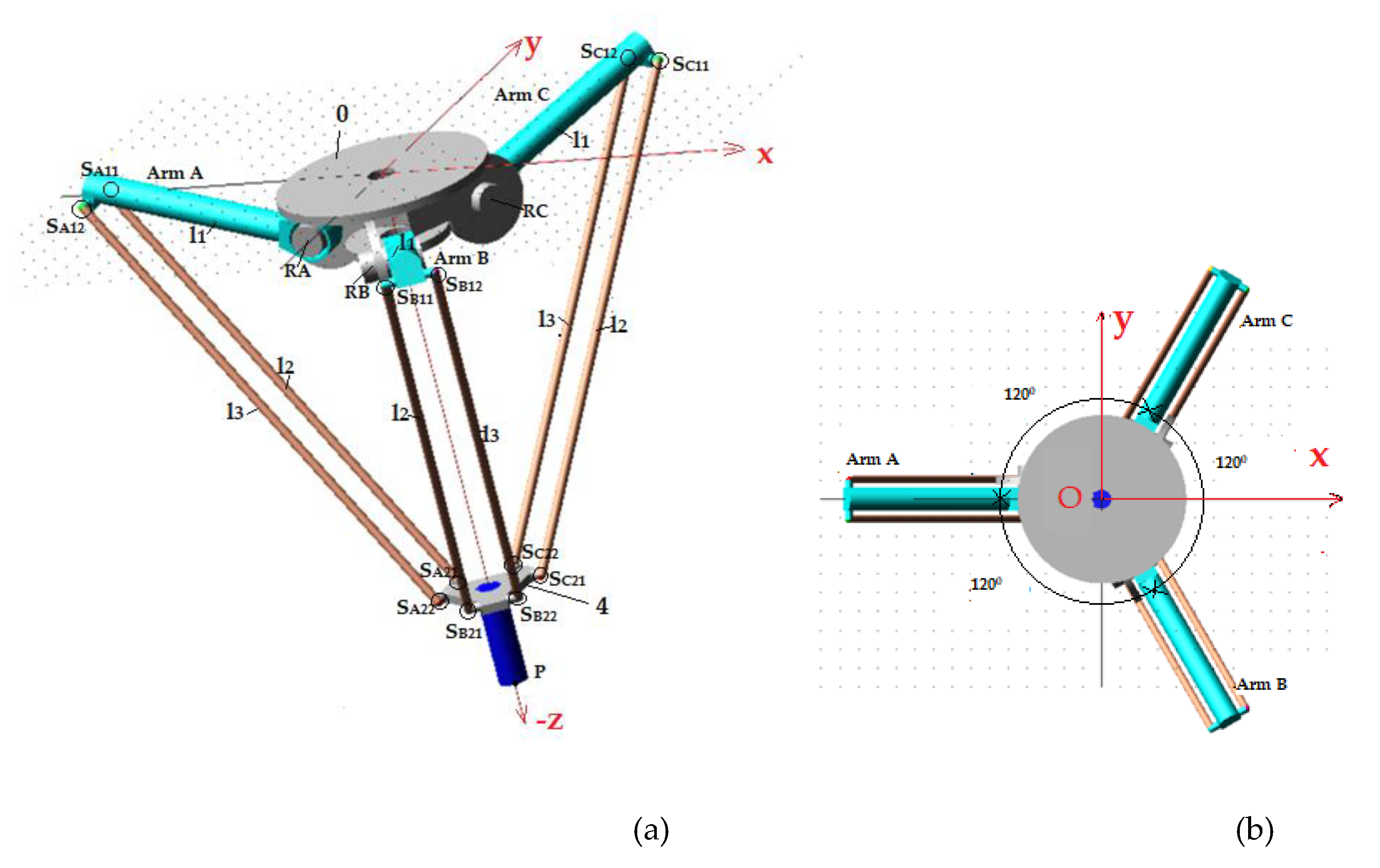
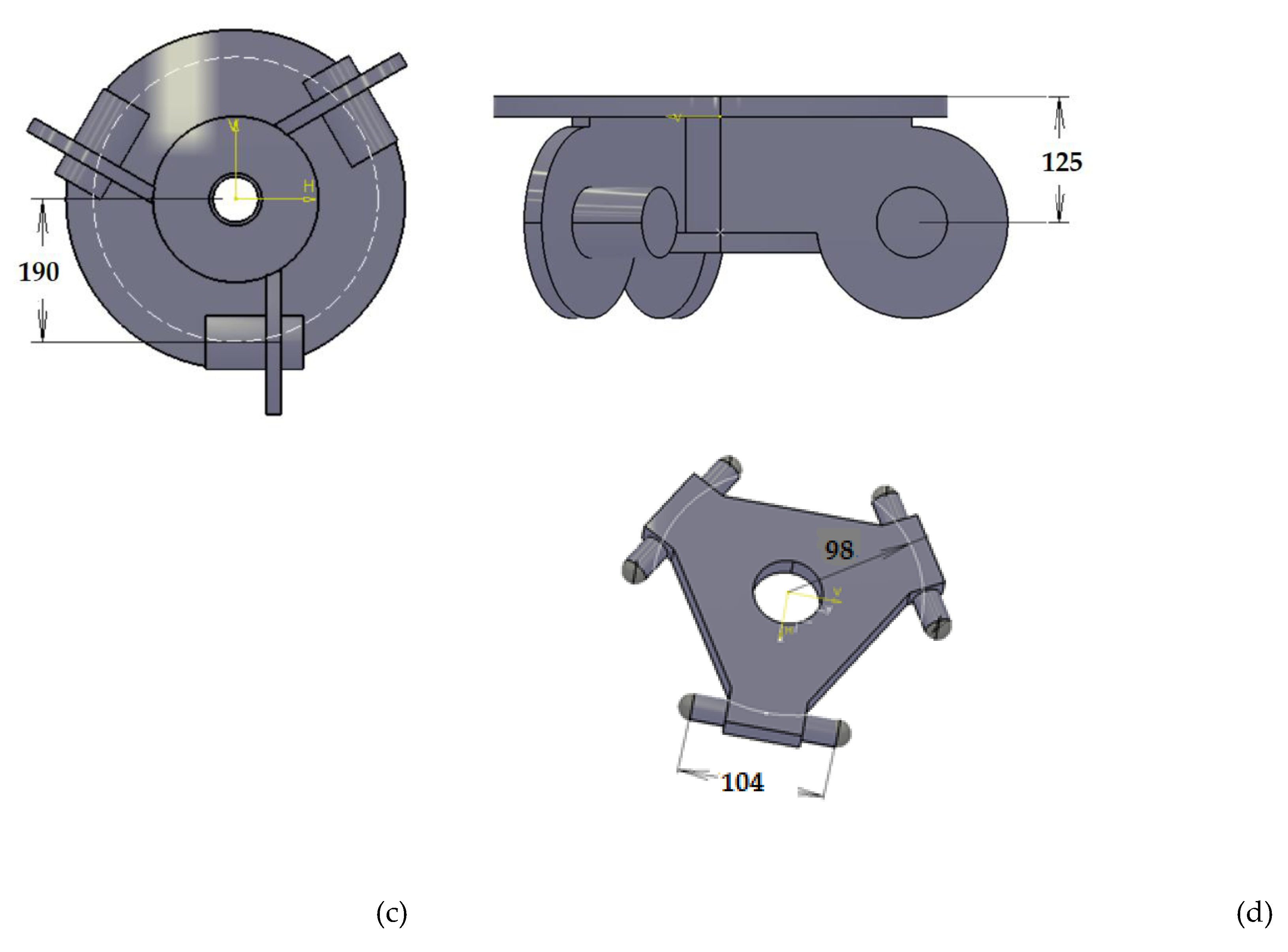
Figure 2.
The Cartezian trajectory of the Delta parallel robot: (a) the initial position; (b) the final position.
Figure 2.
The Cartezian trajectory of the Delta parallel robot: (a) the initial position; (b) the final position.
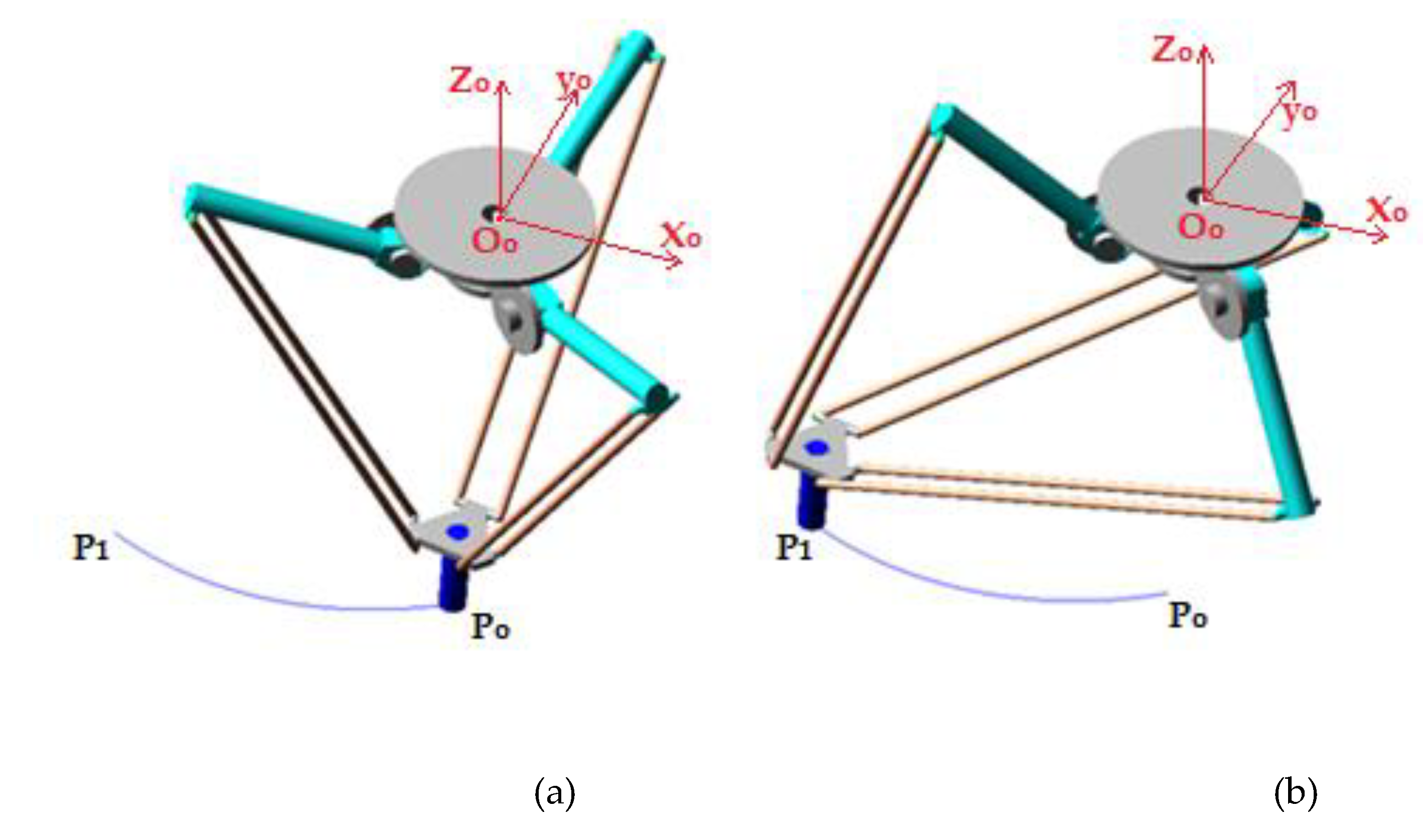
Figure 3.
The motion trajectories in the joint space of the active joints (RA, RB, and RC): (a) angular displacement; (b) angular speed and (c) angular acceleration.
Figure 3.
The motion trajectories in the joint space of the active joints (RA, RB, and RC): (a) angular displacement; (b) angular speed and (c) angular acceleration.
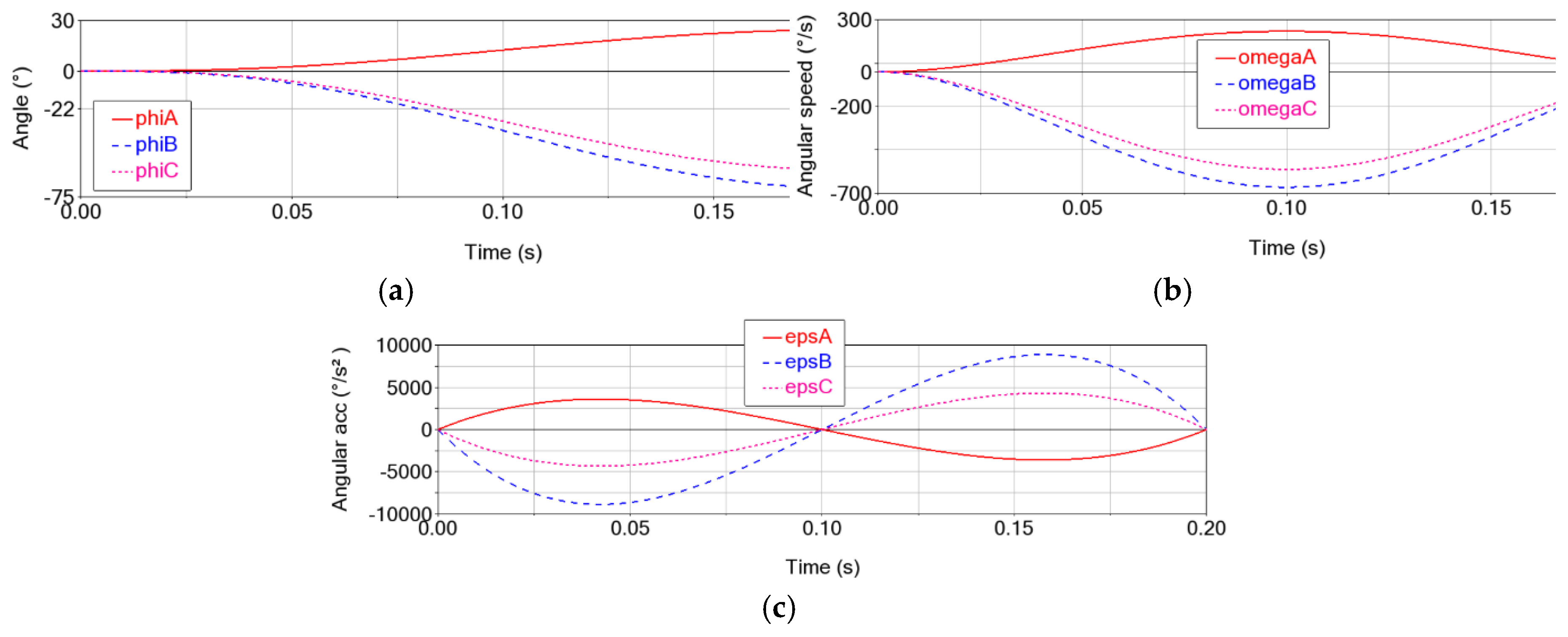
Figure 6.
The motor torques (TA, TB and TC) on the considered trajectory for the Delta parallel robot without clearances.
Figure 6.
The motor torques (TA, TB and TC) on the considered trajectory for the Delta parallel robot without clearances.
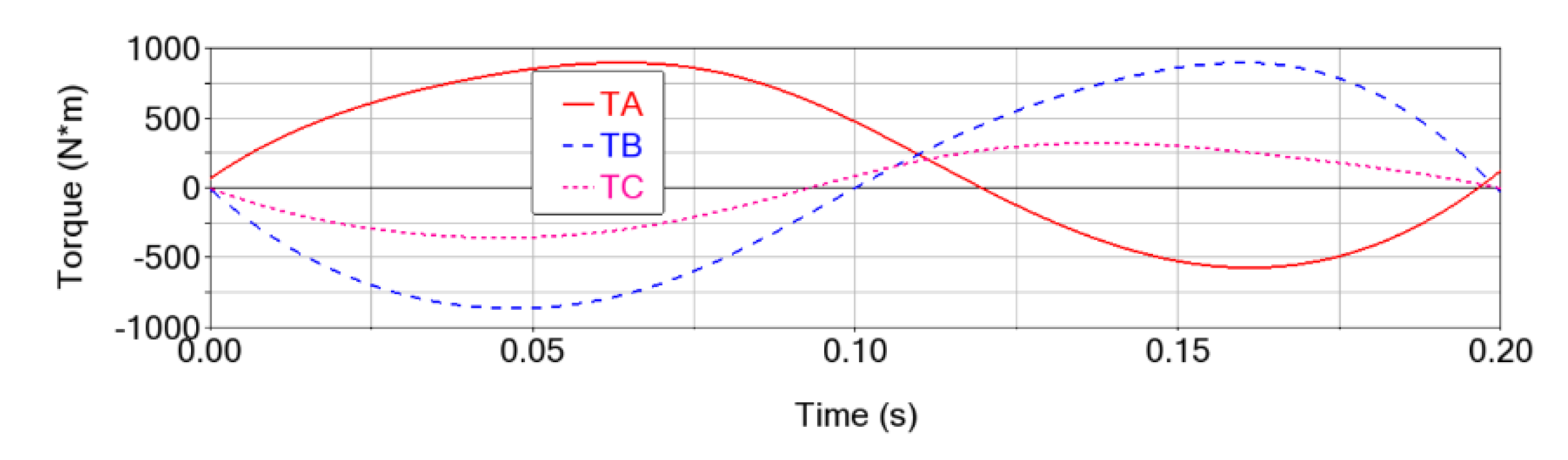
Figure 7.
The clearance in the spherical joints of the Delta parallel robot in the initial position.
Figure 7.
The clearance in the spherical joints of the Delta parallel robot in the initial position.
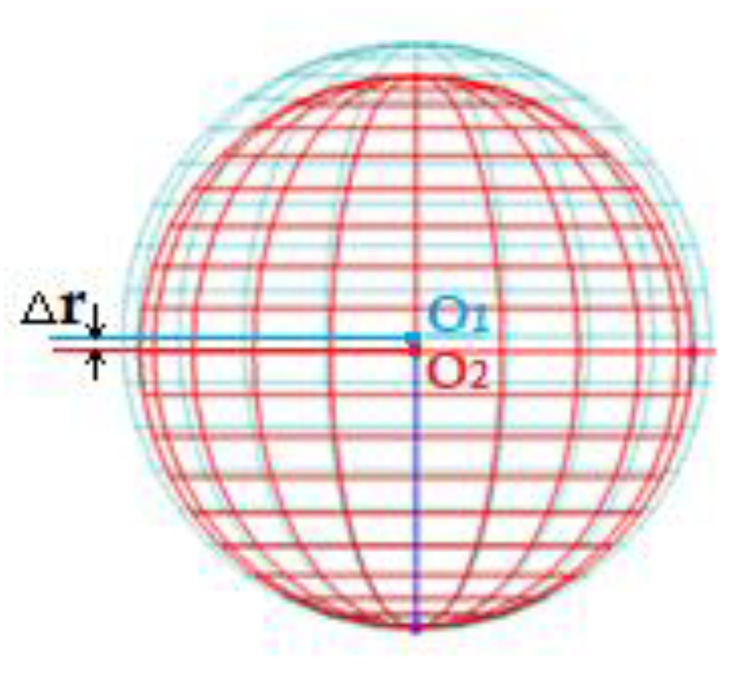
Figure 8.
Motion errors of the end-effector (point P) in the case of clearances in the upper spherical joints of 0.1 mm (red, solid line), 0.2 mm (blue, dash line), 0.3 mm (magenta, dot line), 0.4 mm (midnight_blue DotDash line), 0.5 mm (green, solid line) and 0.6 mm (blue gray, DotDash line), for: (a) displacement; (b) speed and (c) acceleration.
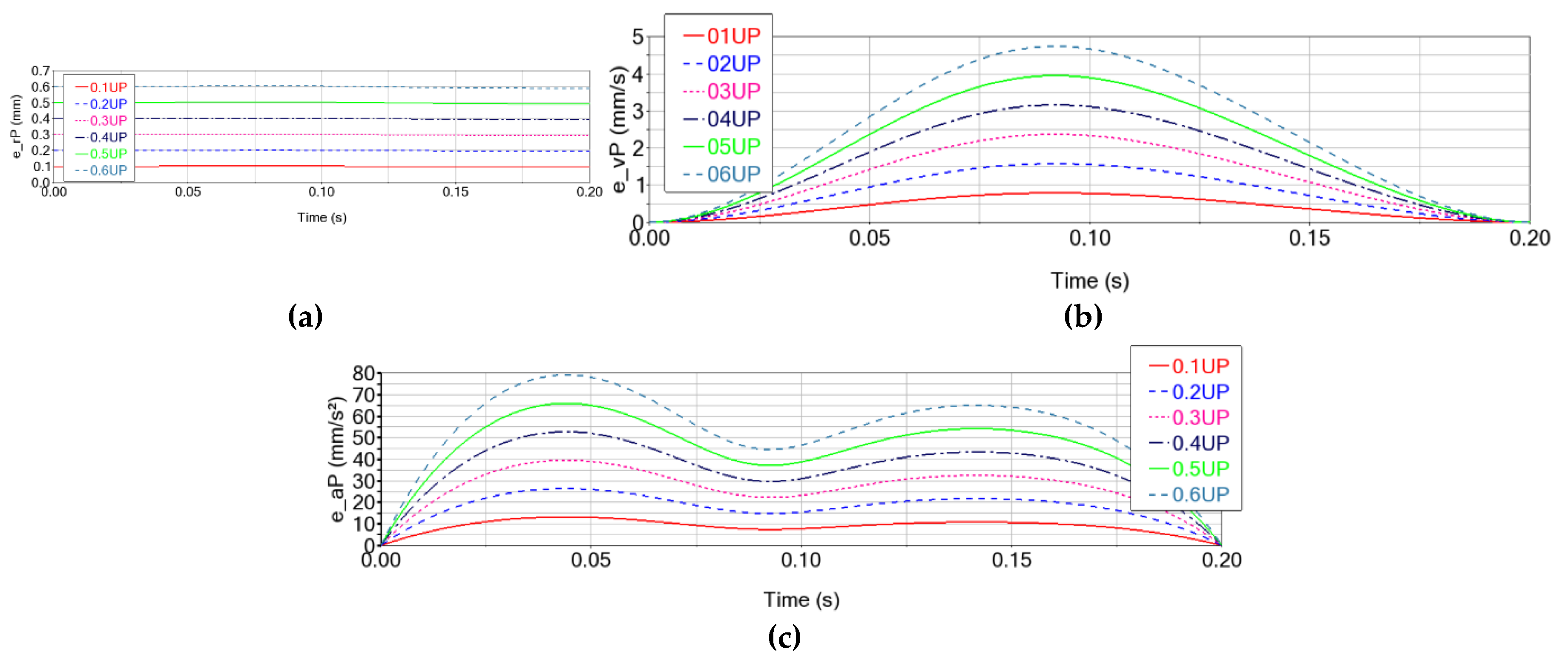
Figure 9.
The displacement error of the characteristic point P in the case of clearances in the upper spherical joints of 0.1 mm (blue, dotdash line), 0.2 mm (magenta, solid line), 0.3 mm (midnight_blue, dash line), 0.4 mm (green, dot line), 0.5 mm (blue gray, dotdash line) and 0.6 mm (red, solid line), on: (a) the X axis; (b) the Y axis and (c) the Z axis.
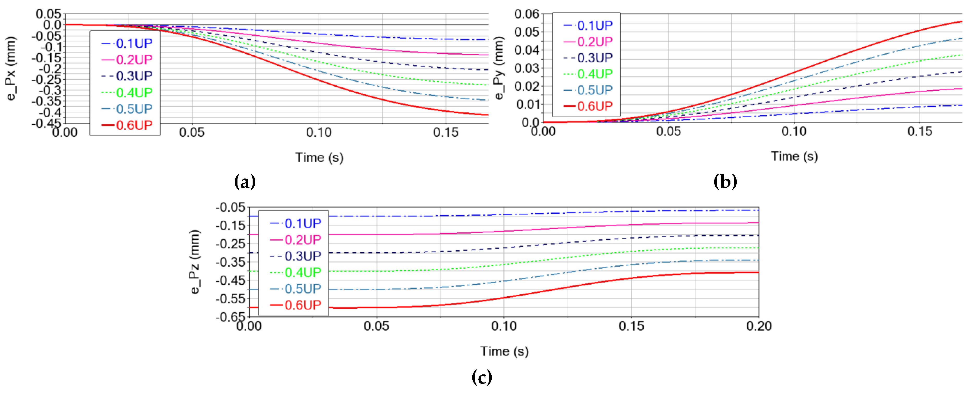
Figure 10.
The speed error of the characteristic point P in the case of clearances in the upper spherical joints of 0.1 mm (blue, dotdash line), 0.2 mm (magenta, solid line), 0.3 mm (midnight_blue, dash line), 0.4 mm (green, dot line), 0.5 mm (blue gray, dotdash line) and 0.6 mm (red, solid line), on: (a) the X axis; (b) the Y axis and (c) the Z axis.
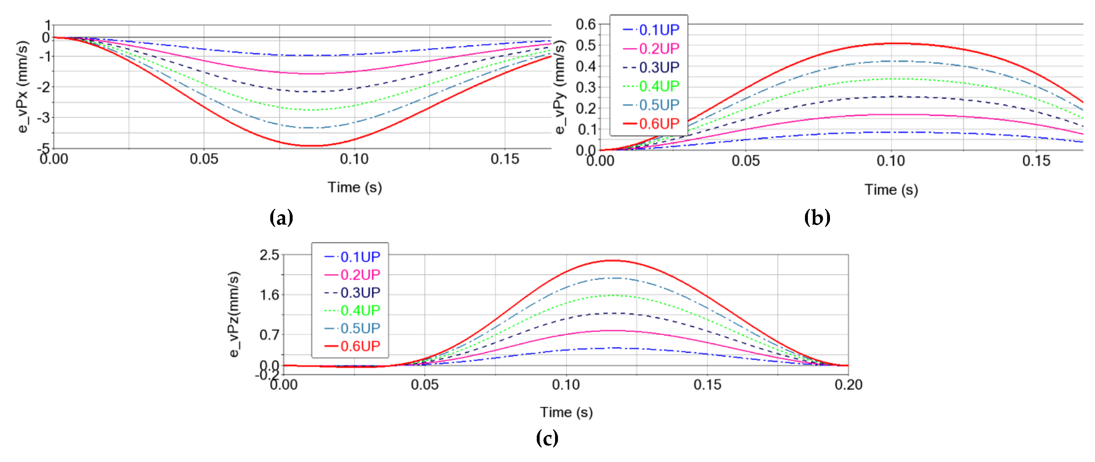
Figure 11.
The acceleration error of the characteristic point P in the case of clearances in the upper spherical joints of 0.1 mm (blue, dotdash line), 0.2 mm (magenta, solid line), 0.3 mm (midnight_blue, dash line), 0.4 mm (green, dot line), 0.5 mm (blue gray, dotdash line) and 0.6 mm (red, solid line), on: (a) the X axis; (b) the Y axis and (c) the Z axis.
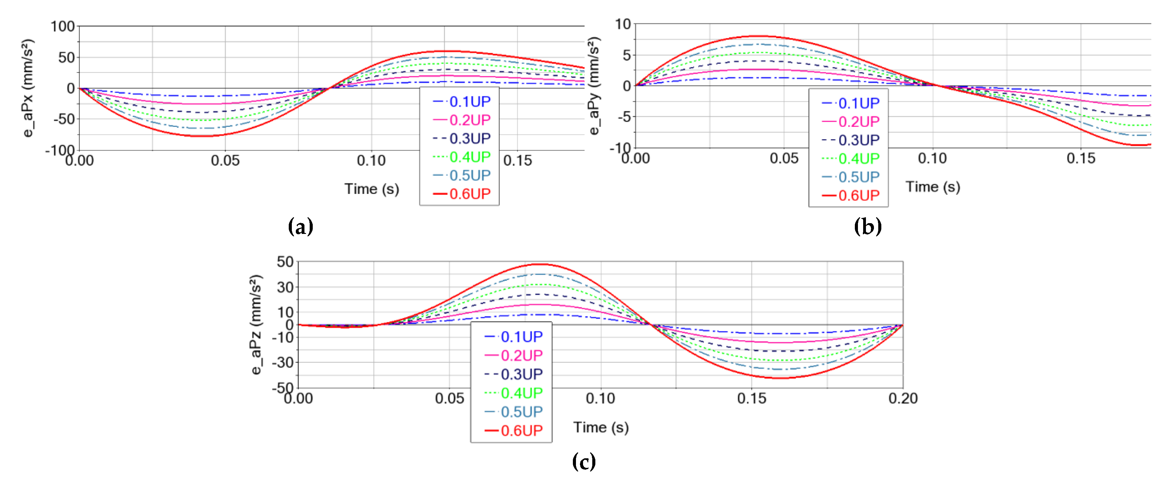
Figure 12.
The motor torque error in the case of clearances in the upper spherical joints with values of 0.1 mm (red, solid line), 0.2 mm (blue, dash line), 0.3 mm (magenta, dot line), 0.4 mm (midnight_blue DotDash line), 0.5 mm (green, solid line) and 0.6 mm (blue gray, DotDash line), for: (a) arm A; (b) arm B and (c) arm C.
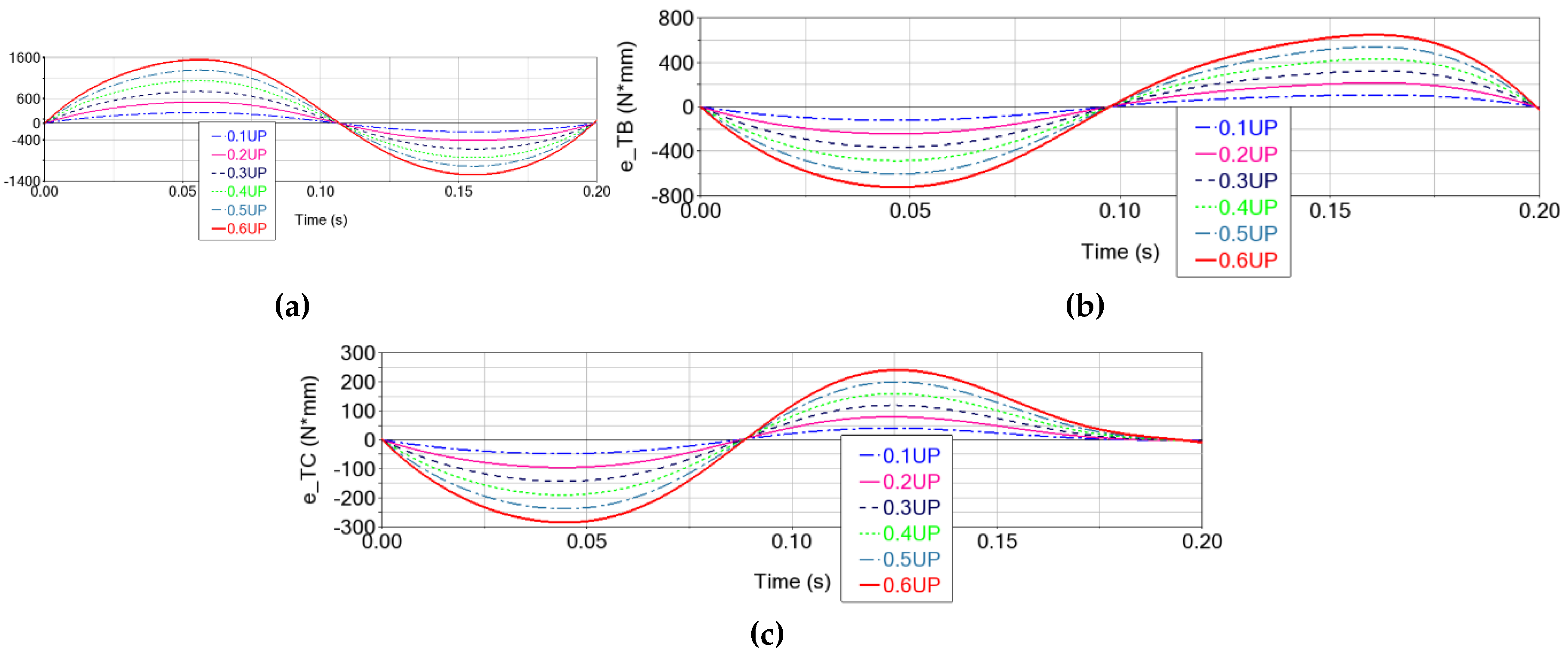
Figure 13.
The error of the characteristic point P motions in the case of clearances in the lower spherical joints of 0.1 mm (red, solid line), 0.2 mm (blue, dash line), 0.3 mm (magenta, dot line), 0.4 mm (midnight_blue DotDash line), 0.5 mm (green, solid line) and 0.6 mm (blue gray, DotDash line), for: (a) displacement; (b) speed and (c) acceleration.
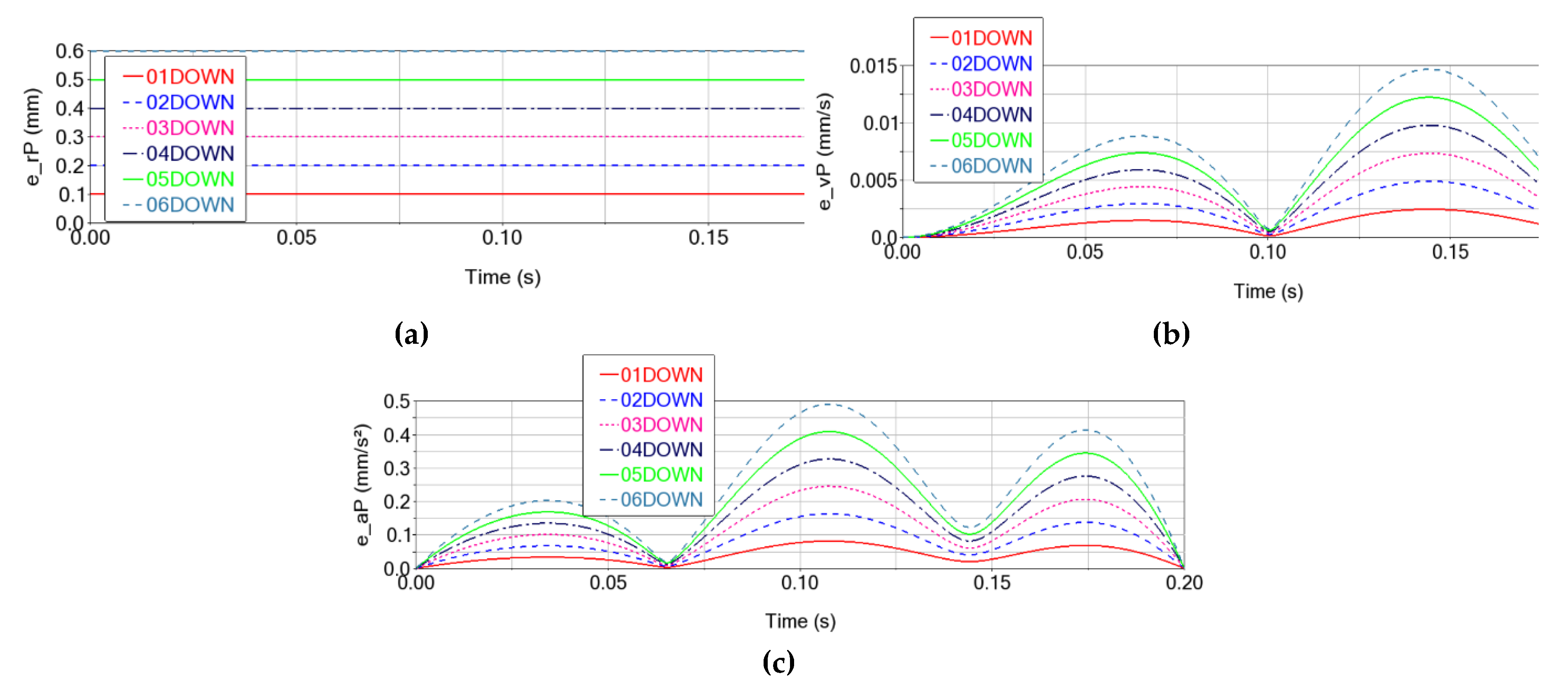
Figure 14.
The Cartesian trajectory of the Delta parallel robot with 0.6 mm clearances in the lower spherical joints: (a) final position; (b) comparative detail of the trajectory with error (Δr = 0.6 mm) vs. the commanded (ideal, Δr = 0 mm) trajectory.
Figure 14.
The Cartesian trajectory of the Delta parallel robot with 0.6 mm clearances in the lower spherical joints: (a) final position; (b) comparative detail of the trajectory with error (Δr = 0.6 mm) vs. the commanded (ideal, Δr = 0 mm) trajectory.
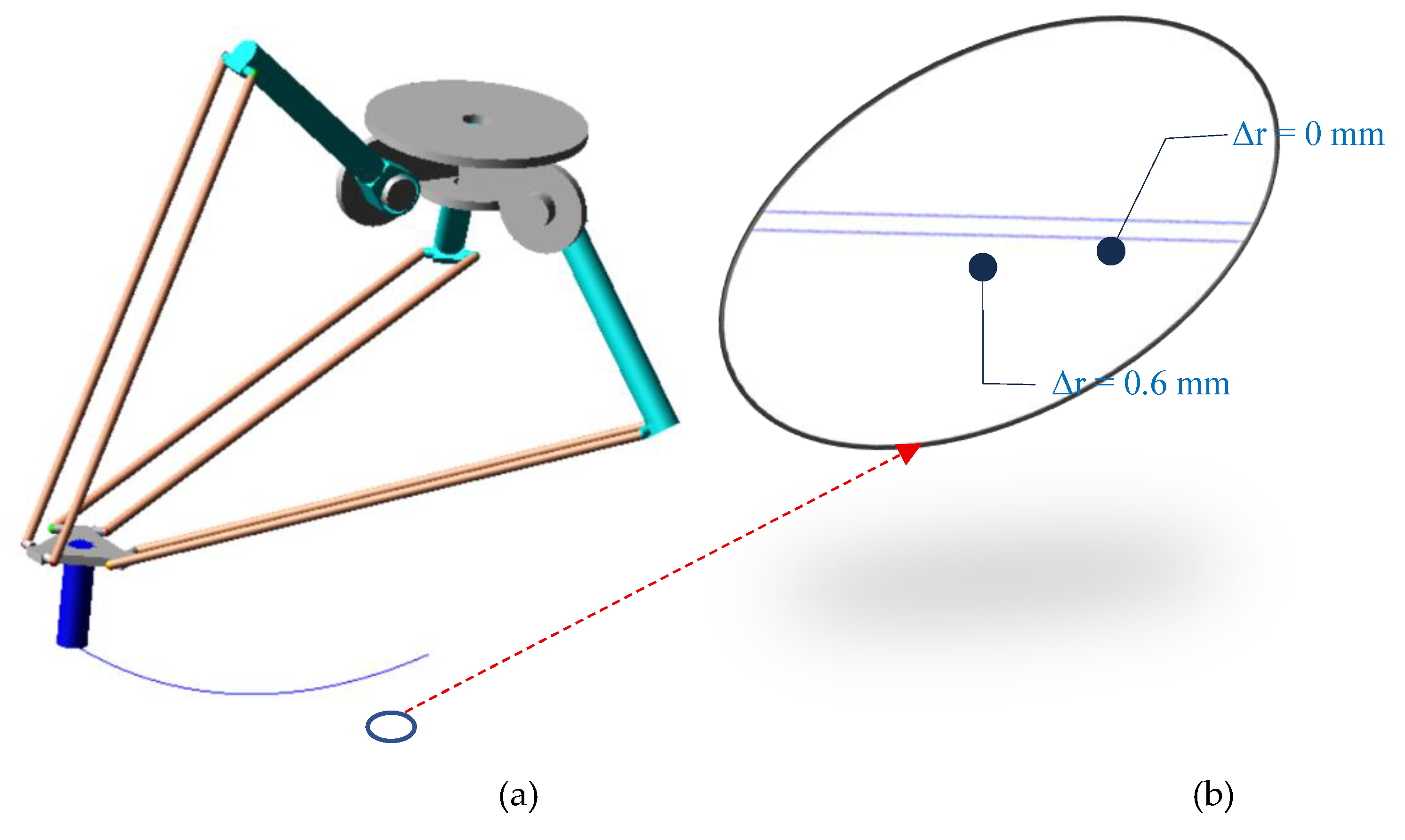
Figure 15.
The motor torque error in the case of clearances in the lower spherical joints with values of 0.1 mm (red, solid line), 0.2 mm (blue, dash line), 0.3 mm (magenta, dot line), 0.4 mm (midnight_blue DotDash line), 0.5 mm (green, solid line) si 0.6 mm (blue gray, DotDash line), for: (a) arm A; (b) arm B and (c) arm C.
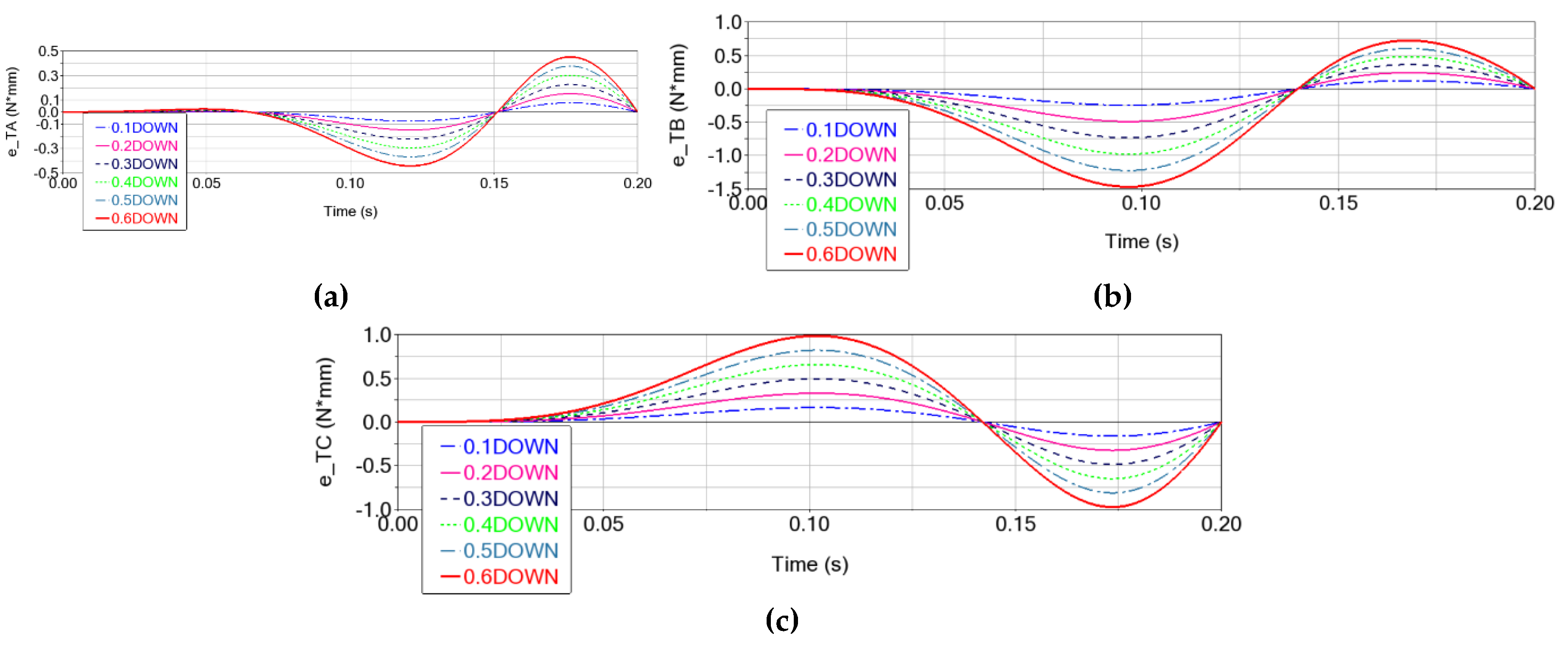
Figure 16.
The error of the characteristic point P motion in the cumulative case of clearances in the upper and lower spherical joints of 0.1 mm (red, solid line), 0.2 mm (blue, dash line), 0.3 mm (magenta, dot line), 0.4 mm (midnight_blue DotDash line), 0.5 mm (green, solid line), and 0.6 mm (blue gray, DotDash line), for: (a) displacement; (b) speed, (c) acceleration.
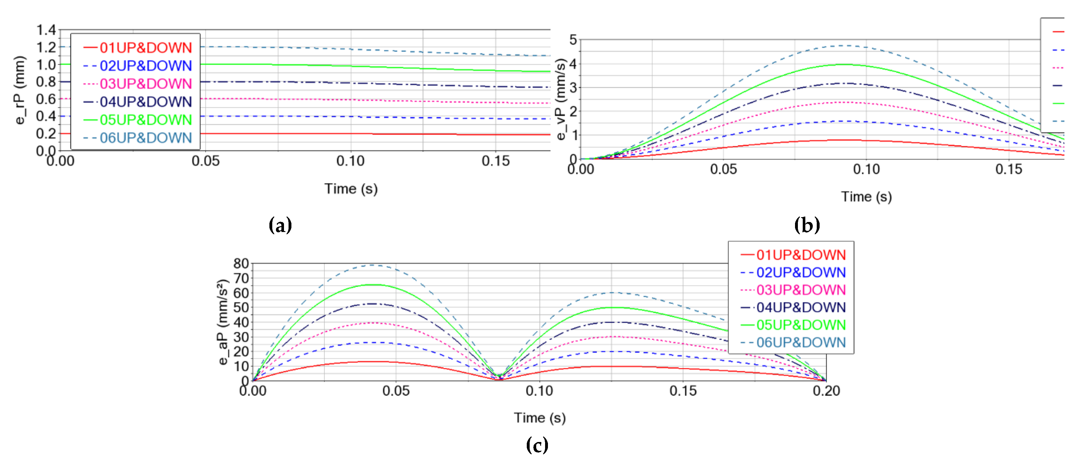
Figure 17.
The motor torque error in the cumulative case of clearances in the upper and lower spherical joints of 0.1 mm (red, solid line), 0.2 mm (blue, dash line), 0.3 mm (magenta, dot line), 0.4 mm (midnight_blue DotDash line), 0.5 mm (green, solid line), and 0.6 mm (blue gray, DotDash line) for: (a) arm A; (b) arm B and (c) arm C.
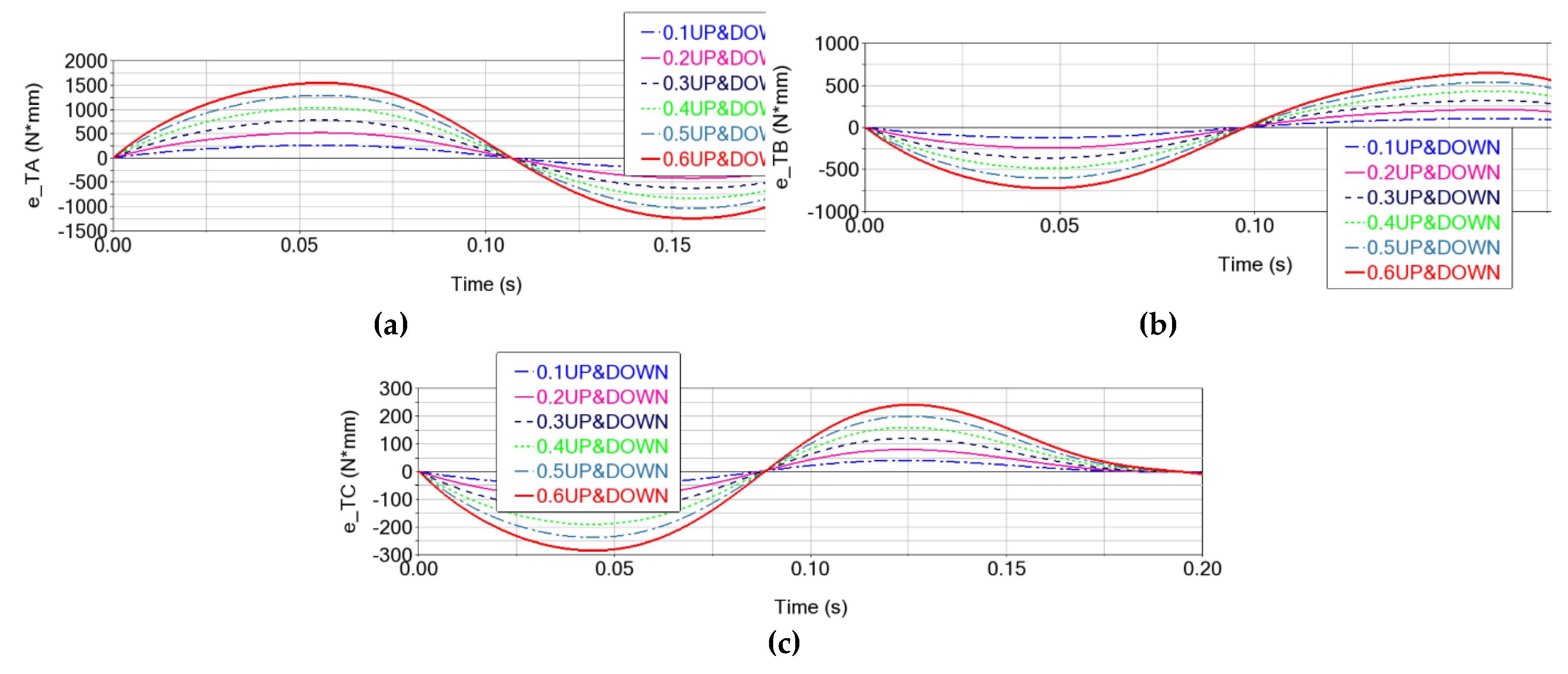

Table 1.
Geometric and Mass Details of the Delta Robot Elements [2].
Table 1.
Geometric and Mass Details of the Delta Robot Elements [2].
| Element | Length [mm] |
Diameter [mm] |
Mass [kg] |
| Fixed platform (0) | - | 434 | 5 |
| Element (1) | 500 | 62 | 1.6 |
| Element (2) and (3) | 1106 | 20 | 0.34 |
| Mobile platform (4) | - | 195 | 0.46 |
| Additional mass (5) | 212 | 50 | 5 |
Table 2.
Maximum kinematic errors on the trajectory (absolute values and percentages of the maximum kinematic parameter value) due to clearances in the upper spherical joints of the Delta robot.
Table 2.
Maximum kinematic errors on the trajectory (absolute values and percentages of the maximum kinematic parameter value) due to clearances in the upper spherical joints of the Delta robot.
|
Jocul [mm] |
e_rPmax [mm] |
Δe_rPmax [mm] |
e_vPmax [mm/s] |
e_aPmax [mm/s2] |
| 0.1 | 0.1008 | 0.0025 | 0.791 (0.009%) | 13.201 (0.011%) |
| 0.2 | 0.2015 | 0.0049 | 1.581 (0.019%) | 26.402 (0.022%) |
| 0.3 | 0.3023 | 0.0074 | 2.372 (0.029%) | 39.602 (0.033%) |
| 0.4 | 0.4030 | 0.0098 | 3.163 (0.039%) | 52.803 (0.044%) |
| 0.5 | 0.5038 | 0.0123 | 3.953 (0.049%) | 66.004 (0.055%) |
| 0.6 | 0.6045 | 0.0147 | 4.744 (0.059%) | 79.204 (0.066%) |
Table 3.
Maximum dynamic errors on the trajectory (absolute values and percentages of the maximum torque value) due to clearances in the upper spherical joints of the Delta robot.
Table 3.
Maximum dynamic errors on the trajectory (absolute values and percentages of the maximum torque value) due to clearances in the upper spherical joints of the Delta robot.
|
Clearance [mm] |
e_TAmax [N·mm] |
e_TBmax [N·mm] |
e_TCmax [N·mm] |
| 0.1 | 260.0 (0.029%) | 121.6 (0.014%) | 47.7 (0.013%) |
| 0.2 | 519.2 (0.057%) | 243.0 (0.027%) | 95.4 (0.026%) |
| 0.3 | 777.5 (0.086%) | 364.0 (0.040%) | 143.0 (0.039%) |
| 0.4 | 1035.2 (0.115%) | 484.6 (0.053%) | 190.6 (0.053%) |
| 0.5 | 1292.3 (0.144%) | 604.7 (0.067%) | 238.1 (0.066%) |
| 0.6 | 1548.9 (0.172%) | 724.3 (0.080%) | 285.5 (0.079%) |
Table 4.
Maximum kinematic errors on the trajectory (absolute values and percentages of the maximum kinematic parameter value) due to clearances in the lower spherical joints of the Delta robot.
Table 4.
Maximum kinematic errors on the trajectory (absolute values and percentages of the maximum kinematic parameter value) due to clearances in the lower spherical joints of the Delta robot.
|
Clearance [mm] |
e_rPmax [mm] |
Δe_rPmax [mm] |
e_vPmax [mm/s] |
e_aPmax [mm/s2] |
| 0.1 | 0.1000 | 0.1·10-9 | 0.0025 (0.000031%) | 0.0819 (0.000068%) |
| 0.2 | 0.2000 | 0.1·10-9 | 0.0049 (0.000061%) | 0.1637 (0.000136%) |
| 0.3 | 0.3000 | 0.1·10-9 | 0.0074 (0.000092%) | 0.2456 (0.000204%) |
| 0.4 | 0.4000 | 0.1·10-9 | 0.0098 (0.000122%) | 0.3274 (0.000272%) |
| 0.5 | 0.5000 | 0.1·10-9 | 0.0123 (0.000153%) | 0.4093 (0.000341%) |
| 0.6 | 0.6000 | 0.1·10-9 | 0.0147 (0.000183%) | 0.4911 (0.000409%) |
Table 5.
Maximum dynamic errors on the trajectory (absolute values and percentages of the maximum kinematic parameter value) due to clearances in the lower spherical joints of the Delta robot.
Table 5.
Maximum dynamic errors on the trajectory (absolute values and percentages of the maximum kinematic parameter value) due to clearances in the lower spherical joints of the Delta robot.
|
Clearance [mm] |
e_TAmax [N·mm] |
e_TBmax [N·mm] |
e_TCmax [N·mm] |
| 0.1 | 0.0754 (0.0000083%) | 0.2448 (0.0000272%) | 0.1644 (0.0000459%) |
| 0.2 | 0.1509 (0.0000168%) | 0.4896 (0.0000545%) | 0.3289 (0.0000918%) |
| 0.3 | 0.2209 (0.0000245%) | 0.7344 (0.0000817%) | 0.4933 (0.0000137%) |
| 0.4 | 0.3018 (0.0000336%) | 0.9792 (0.000109%) | 0.6578 (0.0000183%) |
| 0.5 | 0.3772 (0.0000420%) | 1.2240 (0.000136%) | 0.8222 (0.0000229%) |
| 0.6 | 0.4526 (0.0000504%) | 1.4687 (0.000163%) | 0.9867 (0.0000275%) |
Table 6.
Maximum kinematic errors on the trajectory (absolute values and percentages of the maximum kinematic parameter value) due to clearances in the upper and lower spherical joints of the Delta robot.
Table 6.
Maximum kinematic errors on the trajectory (absolute values and percentages of the maximum kinematic parameter value) due to clearances in the upper and lower spherical joints of the Delta robot.
|
Clearance [mm] |
e_rPmax [mm] |
Δe_rPmax [mm] |
e_vPmax [mm/s] |
e_aPmax [mm/s2] |
| 0.1 | 0.200 | 0.018 | 0.791 (0.009%) | 13.117 (0.0109%) |
| 0.2 | 0.400 | 0.036 | 1.582 (0.019%) | 26.234 (0.0218%) |
| 0.3 | 0.600 | 0.053 | 2.372 (0.029%) | 39.351 (0.0327%) |
| 0.4 | 0.800 | 0.071 | 3.163 (0.039%) | 52.468 (0.0437%) |
| 0.5 | 1.001 | 0.089 | 3.954 (0.049%) | 65.585 (0.0546%) |
| 0.6 | 1.201 | 0.107 | 4.745 (0.059%) | 78.702 (0.0655%) |
Table 7.
Maximum dynamic errors on the trajectory (absolute values and percentages of the maximum kinematic parameter value) due to clearances in the upper and lower spherical joints of the Delta robot.
Table 7.
Maximum dynamic errors on the trajectory (absolute values and percentages of the maximum kinematic parameter value) due to clearances in the upper and lower spherical joints of the Delta robot.
|
Clearance [mm] |
e_TAmax [N·mm] |
e_TBmax [N·mm] |
e_TCmax [N·mm] |
| 0.1 | 260.089 (0.029%) | 121.704 (0.013%) | 47.682 (0.013%) |
| 0.2 | 519.164 (0.057%) | 243.113 (0.027%) | 95.3467 (0.026%) |
| 0.3 | 777.530 (0.086%) | 364.170 (0.040%) | 142.967 (0.039%) |
| 0.4 | 1035.208 (0.115%) | 484.818 (0.053%) | 190.523 (0.053%) |
| 0.5 | 1292.324 (0.144%) | 605.001 (0.067%) | 237.985 (0.066%) |
| 0.6 | 1548.976 (0.172%) | 724.655 (0.080%) | 285.324 (0.079%) |
Disclaimer/Publisher’s Note: The statements, opinions and data contained in all publications are solely those of the individual author(s) and contributor(s) and not of MDPI and/or the editor(s). MDPI and/or the editor(s) disclaim responsibility for any injury to people or property resulting from any ideas, methods, instructions or products referred to in the content. |
© 2025 by the authors. Licensee MDPI, Basel, Switzerland. This article is an open access article distributed under the terms and conditions of the Creative Commons Attribution (CC BY) license (http://creativecommons.org/licenses/by/4.0/).
Copyright: This open access article is published under a Creative Commons CC BY 4.0 license, which permit the free download, distribution, and reuse, provided that the author and preprint are cited in any reuse.


