Submitted:
16 November 2025
Posted:
18 November 2025
You are already at the latest version
Abstract
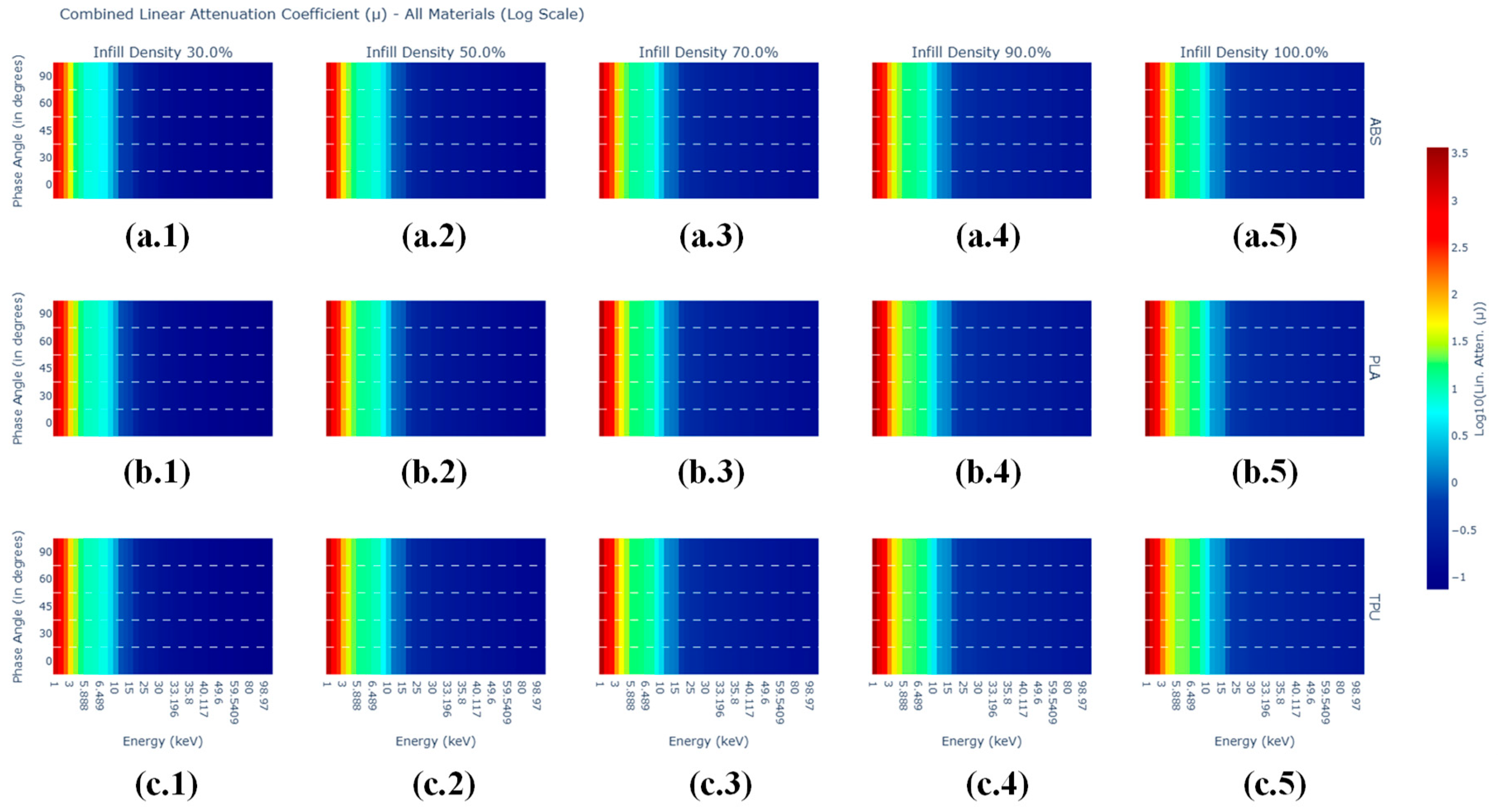
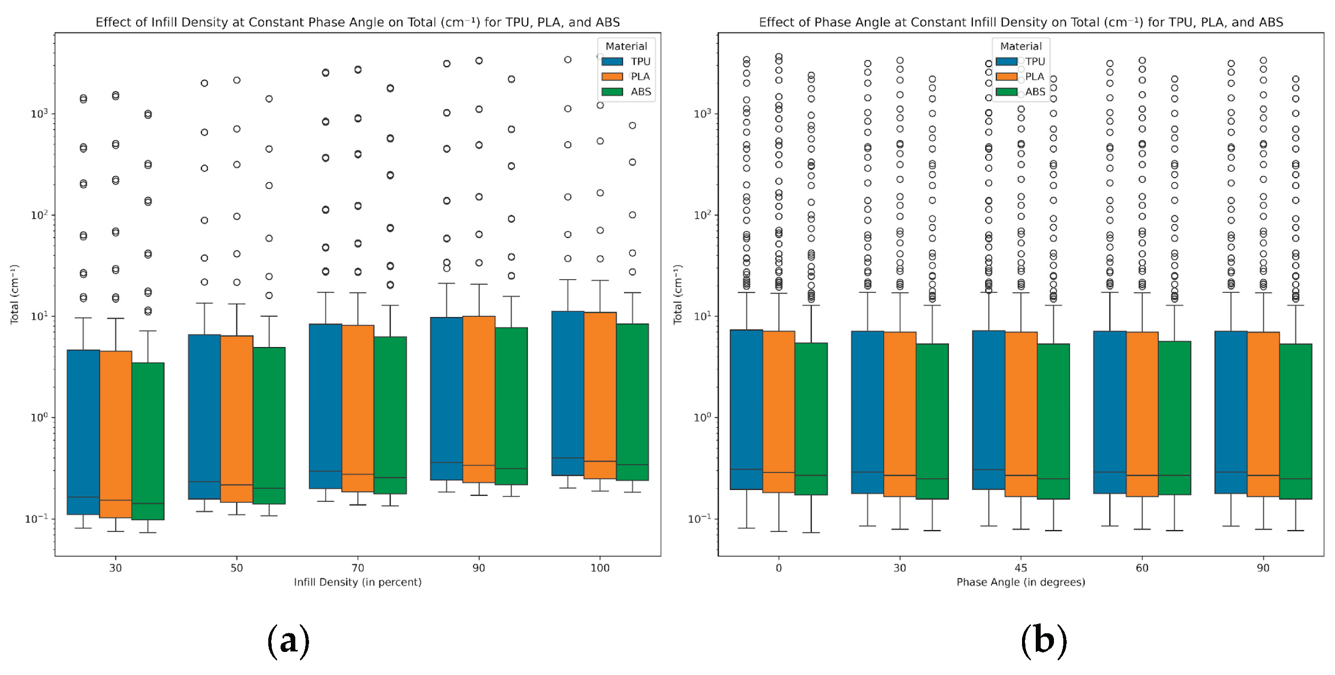
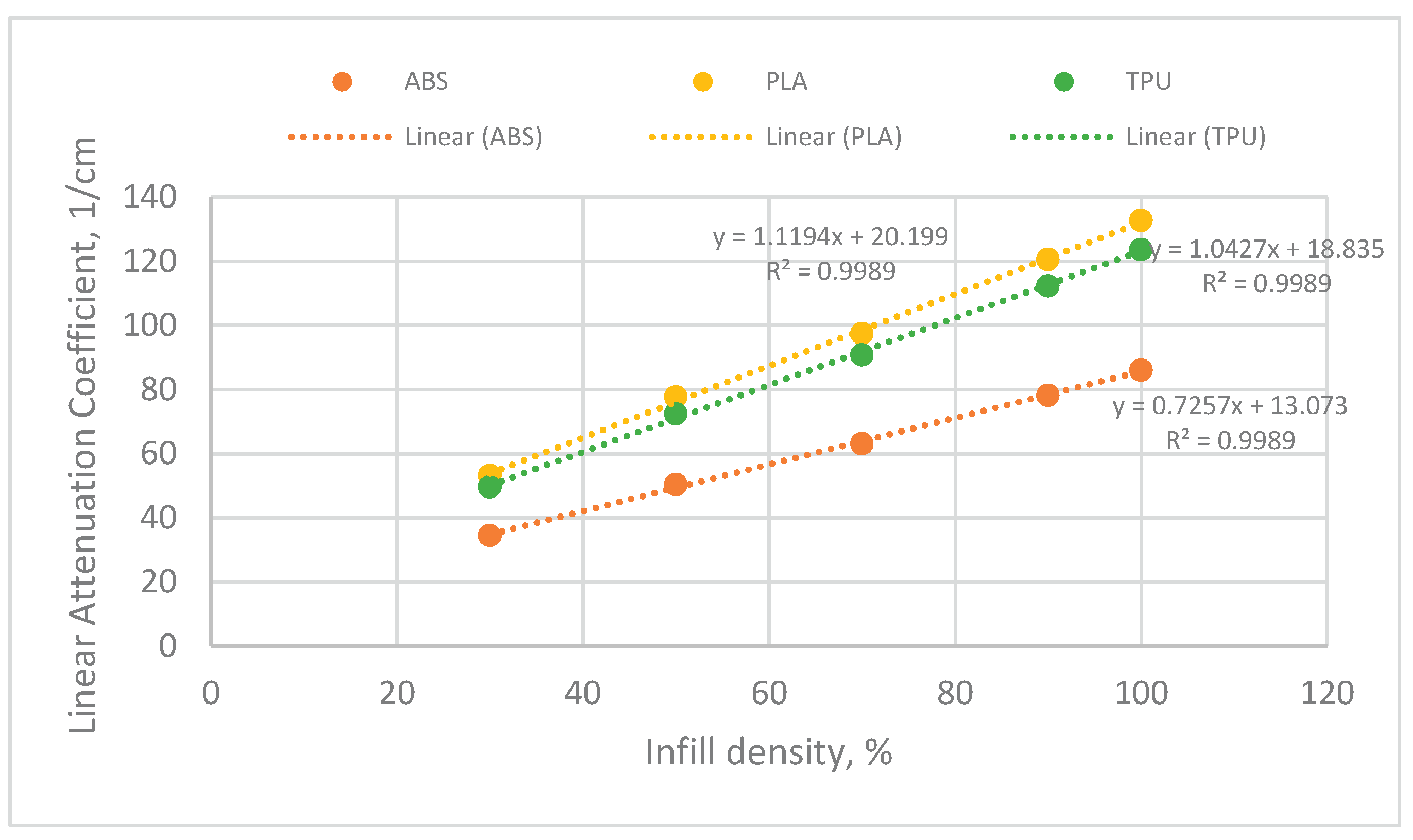
This study investigates the modulation effects of varying infill densities and phase angles on the radiation attenuation properties of three 3D-printed polymers: acrylonitrile butadiene styrene (ABS), polylactic acid (PLA), and thermoplastic polyurethane (TPU). Using the EpiXS software for radiation attenuation simulations, the study assessed the linear attenuation coefficients (LAC) of the materials under different infill densities (30%, 50%, 70%, 90%, and 100%) and phase angles (0°, 30°, 45°, 60°, and 90°) for radiation in the 1-100 keV energy range, which corresponds to the X-ray spectrum. TPU demonstrated the highest attenuation values, with a baseline coefficient of 20.199 cm⁻¹ at 30% infill density, followed by PLA at 18.835 cm⁻¹, and ABS at 13.073 cm⁻¹. Statistical analysis via the Kruskal-Wallis test confirmed that infill density significantly impacts attenuation, while phase angle exhibited no significant effect, with p-values exceeding 0.05 across all materials. TPU showed the highest sensitivity to infill density, with a slope of 1.1194, compared to 0.7257 for ABS and 0.9251 for PLA, making TPU the most suitable candidate for radiation shielding applications, particularly in applications where flexibility and high attenuation are required. The findings support the potential of 3D printing to produce customized, cost-effective radiation protection gear for medical and industrial applications. Future work can further optimize material designs by exploring more complex infill geometries and testing under broader radiation spectra.
Keywords:
1. Introduction
2. Materials and Methods
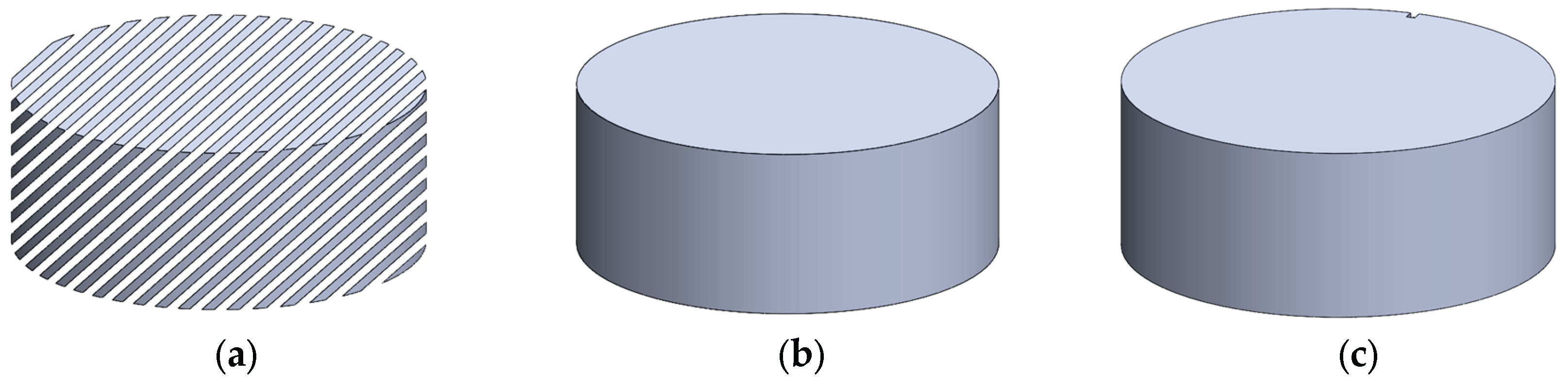
2.1. Computer-Aided Design (CAD) and Theoretical Density Calculation
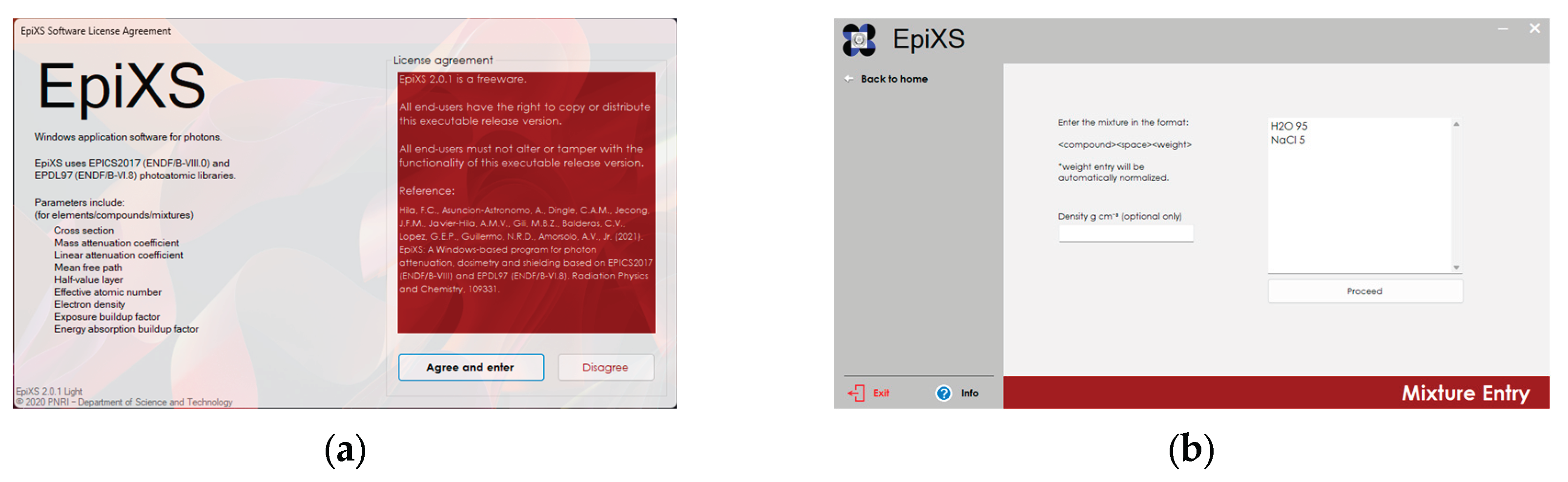
2.2. Radiation Attenuation Simulation
2.3. Statistical Analysis of Linear Attenuation Coefficients
3. Results and Discussion
4. Conclusions
Author Contributions
Funding
Institutional Review Board Statement
Data Availability Statement
Acknowledgments
Conflicts of Interest
Abbreviations
| ABS | Acrylonitrile Butadiene Styrene |
| PLA | Polylactic Acid |
| TPU | Thermoplastic Polyurethane |
| CAD | Computer-Aided Design |
| LAC | Linear Attenuation Coefficient |
References
- S. M. Magrini et al., “Applying radiation protection and safety in radiotherapy,” Radiol Med, vol. 124, no. 8, pp. 777–782, Aug. 2019. [CrossRef]
- Ploussi, E. P. Efstathopoulos, and E. Brountzos, “The Importance of Radiation Protection Education and Training for Medical Professionals of All Specialties,” Cardiovasc Intervent Radiol, vol. 44, no. 6, pp. 829–834, Jun. 2021. [CrossRef]
- M. Kitahara et al., “Cancer and circulatory disease risks in US radiologic technologists associated with performing procedures involving radionuclides,” Occup Environ Med, vol. 72, no. 11, pp. 770–776, Nov. 2015. [CrossRef]
- S. J. Talley et al., “Flexible 3D printed silicones for gamma and neutron radiation shielding,” Radiation Physics and Chemistry, vol. 188, p. 109616, Nov. 2021. [CrossRef]
- F. Kharfi et al., “Implementation of 3D Printing and Modeling Technologies for the Fabrication of Dose Boluses for External Radiotherapy at the CLCC of Sétif, Algeria,” Technol Cancer Res Treat, vol. 23, Jan. 2024. [CrossRef]
- MIRA Safety, “MIRA Safety HAZ-SUIT Protective CBRN HAZMAT Suit,” https://www.mirasafety.com/products/mira-safety-haz-suit-hazmat-suit?srsltid=AfmBOoqhBKbIQBDdzPsxVIQiR514TNeLpsu4taPO9OZQ__FtPnA4GtOt.
- V. More, Z. Alsayed, Mohamed. S. Badawi, Abouzeid. A. Thabet, and P. P. Pawar, “Polymeric composite materials for radiation shielding: a review,” Environ Chem Lett, vol. 19, no. 3, pp. 2057–2090, Jun. 2021. [CrossRef]
- G. ALMisned et al., “Novel Cu/Zn Reinforced Polymer Composites: Experimental Characterization for Radiation Protection Efficiency (RPE) and Shielding Properties for Alpha, Proton, Neutron, and Gamma Radiations,” Polymers (Basel), vol. 13, no. 18, p. 3157, Sep. 2021. [CrossRef]
- K. Mokhtari, M. K. Saadi, H. A. Panahi, and G. Jahanfarnia, “The shielding properties of the ordinary concrete reinforced with innovative nano polymer particles containing PbO–H3BO3 for dual protection against gamma and neutron radiations,” Radiation Physics and Chemistry, vol. 189, p. 109711, Dec. 2021. [CrossRef]
- InFab, “Radiation Shielding.” Accessed: Jul. 06, 2023. [Online]. Available: https://infabcorp.com/products/radiation-shielding/.
- J. P. McCaffrey, H. Shen, B. Downton, and E. Mainegra--Hing, “Radiation attenuation by lead and nonlead materials used in radiation shielding garments,” Med Phys, vol. 34, no. 2, pp. 530–537, Feb. 2007. [CrossRef]
- Beck et al., “Additive Manufacturing of Multimaterial Composites for Radiation Shielding and Thermal Management,” ACS Appl Mater Interfaces, vol. 15, no. 29, pp. 35400–35410, Jul. 2023. [CrossRef]
- K. Jakupi, V. Dukovski, and A. Kočov, “Analysis of additive manufacturing technology input parameters in manufacturing of bolus,” Mechanical Engieneering – Scientific Journal, vol. 40, no. 1, pp. 17–22, 2022. [CrossRef]
- J. A. Diaz-Merchan, S. A. Martinez-Ovalle, and H. R. Vega-Carrillo, “Development of a 3D printing process of bolus using BolusCM material for radiotherapy with electrons,” Applied Radiation and Isotopes, vol. 199, p. 110899, Sep. 2023. [CrossRef]
- G. Sands, C. H. Clark, and C. K. McGarry, “A review of 3D printing utilisation in radiotherapy in the United Kingdom and Republic of Ireland,” Physica Medica, vol. 115, p. 103143, Nov. 2023. [CrossRef]
- C. Hila et al., “EpiXS: A Windows-based program for photon attenuation, dosimetry and shielding based on EPICS2017 (ENDF/B-VIII) and EPDL97 (ENDF/B-VI.8),” Radiation Physics and Chemistry, vol. 182, p. 109331, May 2021. [CrossRef]
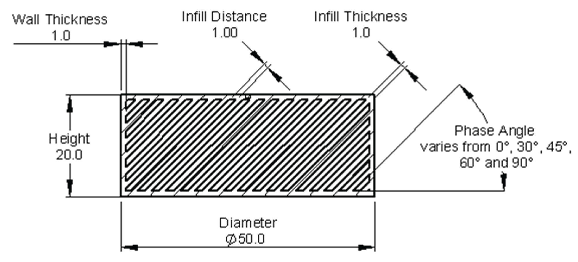


| Infill Density, % | Distance of Infills, mm |
|---|---|
| 30 | 2.33 |
| 50 | 1.00 |
| 70 | 0.44 |
| 90 | 0.11 |
| 100 | - |
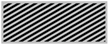
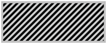
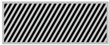
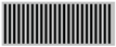
| Infill Density (%) | Angle | ||||
| 0° | 30° | 45° | 60° | 90° | |
| 30% |  |
 |
 |
 |
 |
| 50% |  |
 |
 |
 |
 |
| 70% |  |
 |
 |
 |
 |
| 90% |  |
 |
 |
 |
 |
| Material | Infill Density | Infill Phase Angle | Theoretical Volume with airgap, cm3 |
Theoretical Volume of Infill, cm3 |
Theoretical Mass, g | Theoretical density, g/cm3 |
|---|---|---|---|---|---|---|
| ABS | 30 | 0 | 39.25 | 15.746 | 17.64 | 0.44931 |
| ABS | 50 | 0 | 39.25 | 22.984 | 25.74 | 0.65585 |
| ABS | 70 | 0 | 39.25 | 28.815 | 32.27 | 0.82224 |
| ABS | 90 | 0 | 39.25 | 35.651 | 39.93 | 1.01730 |
| ABS | 100 | 0 | 39.25 | 39.25 | 43.96 | 1.12000 |
| PLA | 30 | 0 | 39.25 | 15.746 | 18.42 | 0.46937 |
| PLA | 50 | 0 | 39.25 | 22.984 | 26.89 | 0.68513 |
| PLA | 70 | 0 | 39.25 | 28.815 | 33.71 | 0.85894 |
| PLA | 90 | 0 | 39.25 | 35.651 | 41.71 | 1.06272 |
| PLA | 100 | 0 | 39.25 | 39.25 | 45.92 | 1.17000 |
| TPU | 30 | 0 | 39.25 | 15.746 | 19.21 | 0.48943 |
| TPU | 50 | 0 | 39.25 | 22.984 | 28.04 | 0.71441 |
| TPU | 70 | 0 | 39.25 | 28.815 | 35.15 | 0.89565 |
| TPU | 90 | 0 | 39.25 | 35.651 | 43.49 | 1.10813 |
| TPU | 100 | 0 | 39.25 | 39.25 | 47.89 | 1.22000 |
| ABS | 30 | 30 | 39.25 | 16.471 | 18.45 | 0.47000 |
| ABS | 50 | 30 | 39.25 | 22.981 | 25.74 | 0.65576 |
| ABS | 70 | 30 | 39.25 | 29.498 | 33.04 | 0.84173 |
| ABS | 90 | 30 | 39.25 | 36.013 | 40.33 | 1.02763 |
| ABS | 100 | 30 | 39.25 | 39.25 | 43.96 | 1.12000 |
| PLA | 30 | 30 | 39.25 | 16.471 | 19.27 | 0.49098 |
| PLA | 50 | 30 | 39.25 | 22.981 | 26.89 | 0.68504 |
| PLA | 70 | 30 | 39.25 | 29.498 | 34.51 | 0.87930 |
| PLA | 90 | 30 | 39.25 | 36.013 | 42.14 | 1.07351 |
| PLA | 100 | 30 | 39.25 | 39.25 | 45.92 | 1.17000 |
| TPU | 30 | 30 | 39.25 | 16.471 | 20.09 | 0.51196 |
| TPU | 50 | 30 | 39.25 | 22.981 | 28.04 | 0.71431 |
| TPU | 70 | 30 | 39.25 | 29.498 | 35.99 | 0.91688 |
| TPU | 90 | 30 | 39.25 | 36.013 | 43.94 | 1.11938 |
| TPU | 100 | 30 | 39.25 | 39.25 | 47.89 | 1.22000 |
| ABS | 30 | 0 | 39.25 | 15.746 | 17.64 | 0.44931 |
| ABS | 30 | 30 | 39.25 | 16.471 | 18.45 | 0.47000 |
| ABS | 30 | 45 | 39.25 | 16.468 | 18.44 | 0.46991 |
| ABS | 30 | 60 | 39.25 | 16.474 | 18.45 | 0.47009 |
| ABS | 30 | 90 | 39.25 | 16.438 | 18.41 | 0.46906 |
| PLA | 30 | 0 | 39.25 | 15.746 | 18.42 | 0.46937 |
| PLA | 30 | 30 | 39.25 | 16.471 | 19.27 | 0.49098 |
| PLA | 30 | 45 | 39.25 | 16.468 | 19.27 | 0.49089 |
| PLA | 30 | 60 | 39.25 | 16.474 | 19.27 | 0.49107 |
| PLA | 30 | 90 | 39.25 | 16.438 | 19.23 | 0.49000 |
| TPU | 30 | 0 | 39.25 | 15.746 | 19.21 | 0.48943 |
| TPU | 30 | 30 | 39.25 | 16.471 | 20.09 | 0.51196 |
| TPU | 30 | 45 | 39.25 | 16.468 | 20.09 | 0.51187 |
| TPU | 30 | 60 | 39.25 | 16.474 | 20.10 | 0.51206 |
| TPU | 30 | 90 | 39.25 | 16.438 | 20.05 | 0.51094 |
| ABS | 50 | 0 | 39.25 | 22.984 | 25.74 | 0.65585 |
| ABS | 50 | 30 | 39.25 | 22.981 | 25.74 | 0.65576 |
| ABS | 50 | 45 | 39.25 | 22.984 | 25.74 | 0.65585 |
| ABS | 50 | 60 | 39.25 | 22.983 | 25.74 | 0.65582 |
| ABS | 50 | 90 | 39.25 | 22.983 | 25.74 | 0.65582 |
| PLA | 50 | 0 | 39.25 | 22.984 | 26.89 | 0.68513 |
| PLA | 50 | 30 | 39.25 | 22.981 | 26.89 | 0.68504 |
| PLA | 50 | 45 | 39.25 | 22.984 | 26.89 | 0.68513 |
| PLA | 50 | 60 | 39.25 | 22.983 | 26.89 | 0.68510 |
| PLA | 50 | 90 | 39.25 | 22.983 | 26.89 | 0.68510 |
| TPU | 50 | 0 | 39.25 | 22.984 | 28.04 | 0.71441 |
| TPU | 50 | 30 | 39.25 | 22.981 | 28.04 | 0.71431 |
| TPU | 50 | 45 | 39.25 | 22.984 | 28.04 | 0.71441 |
| TPU | 50 | 60 | 39.25 | 22.983 | 28.04 | 0.71438 |
| TPU | 50 | 90 | 39.25 | 22.983 | 28.04 | 0.71438 |
| ABS | 70 | 0 | 39.25 | 28.815 | 32.27 | 0.82224 |
| ABS | 70 | 30 | 39.25 | 29.498 | 33.04 | 0.84173 |
| ABS | 70 | 45 | 39.25 | 29.497 | 33.04 | 0.84170 |
| ABS | 70 | 60 | 39.25 | 29.497 | 33.04 | 0.84170 |
| ABS | 70 | 90 | 39.25 | 29.483 | 33.02 | 0.84130 |
| PLA | 70 | 0 | 39.25 | 28.815 | 33.71 | 0.85894 |
| PLA | 70 | 30 | 39.25 | 29.498 | 34.51 | 0.87930 |
| PLA | 70 | 45 | 39.25 | 29.497 | 34.51 | 0.87927 |
| PLA | 70 | 60 | 39.25 | 29.497 | 34.51 | 0.87927 |
| PLA | 70 | 90 | 39.25 | 29.483 | 34.50 | 0.87886 |
| TPU | 70 | 0 | 39.25 | 28.815 | 35.15 | 0.89565 |
| TPU | 70 | 30 | 39.25 | 29.498 | 35.99 | 0.91688 |
| TPU | 70 | 45 | 39.25 | 29.497 | 35.99 | 0.91685 |
| TPU | 70 | 60 | 39.25 | 29.497 | 35.99 | 0.91685 |
| TPU | 70 | 90 | 39.25 | 29.483 | 35.97 | 0.91641 |
| ABS | 90 | 0 | 39.25 | 35.651 | 39.93 | 1.01730 |
| ABS | 90 | 30 | 39.25 | 36.013 | 40.33 | 1.02763 |
| ABS | 90 | 45 | 39.25 | 36.013 | 40.33 | 1.02763 |
| ABS | 90 | 60 | 39.25 | 36.013 | 40.33 | 1.02763 |
| ABS | 90 | 90 | 39.25 | 36.011 | 40.33 | 1.02758 |
| PLA | 90 | 0 | 39.25 | 35.651 | 41.71 | 1.06272 |
| PLA | 90 | 30 | 39.25 | 36.013 | 42.14 | 1.07351 |
| PLA | 90 | 45 | 39.25 | 36.013 | 42.14 | 1.07351 |
| PLA | 90 | 60 | 39.25 | 36.013 | 42.14 | 1.07351 |
| PLA | 90 | 90 | 39.25 | 36.011 | 42.13 | 1.07345 |
| TPU | 90 | 0 | 39.25 | 35.651 | 43.49 | 1.10813 |
| TPU | 90 | 30 | 39.25 | 36.013 | 43.94 | 1.11938 |
| TPU | 90 | 45 | 39.25 | 36.013 | 43.94 | 1.11938 |
| TPU | 90 | 60 | 39.25 | 36.013 | 43.94 | 1.11938 |
| TPU | 90 | 90 | 39.25 | 36.011 | 43.93 | 1.11932 |
| Varying Infill Density at Constant Phase Angle | |||
|---|---|---|---|
| Material | Phase Angle, (o) | p-value | Statistical Significance |
| ABS | 0 | 0.000184 | Yes |
| ABS | 30 | 0.001226 | Yes |
| ABS | 45 | 0.001219 | Yes |
| ABS | 60 | 0.000199 | Yes |
| ABS | 90 | 0.001226 | Yes |
| PLA | 0 | 0.000431 | Yes |
| PLA | 30 | 0.002435 | Yes |
| PLA | 45 | 0.002435 | Yes |
| PLA | 60 | 0.002435 | Yes |
| PLA | 90 | 0.002406 | Yes |
| TPU | 0 | 0.000420 | Yes |
| TPU | 30 | 0.002388 | Yes |
| TPU | 45 | 0.000567 | Yes |
| TPU | 60 | 0.002377 | Yes |
| TPU | 90 | 0.002350 | Yes |
| Varying Phase Angle at Constant Infill Density | |||
| Material | Infill Density, % | p-value | Statistical Significance |
| ABS | 30 | 0.986465 | No |
| ABS | 50 | 0.998844 | No |
| ABS | 70 | 0.994958 | No |
| ABS | 90 | 0.996336 | No |
| PLA | 30 | 0.987389 | No |
| PLA | 50 | 0.998844 | No |
| PLA | 70 | 0.995209 | No |
| PLA | 90 | 0.997087 | No |
| TPU | 30 | 0.987771 | No |
| TPU | 50 | 0.998844 | No |
| TPU | 70 | 0.994958 | No |
| TPU | 90 | 0.991924 | No |
Disclaimer/Publisher’s Note: The statements, opinions and data contained in all publications are solely those of the individual author(s) and contributor(s) and not of MDPI and/or the editor(s). MDPI and/or the editor(s) disclaim responsibility for any injury to people or property resulting from any ideas, methods, instructions or products referred to in the content. |
© 2025 by the authors. Licensee MDPI, Basel, Switzerland. This article is an open access article distributed under the terms and conditions of the Creative Commons Attribution (CC BY) license (http://creativecommons.org/licenses/by/4.0/).


