Submitted:
15 November 2025
Posted:
17 November 2025
You are already at the latest version
Abstract
The present paper investigates generation of the alternating almost zero and strong homogeneous magnetic field for rotary magnetic refrigeration. In order to achieve alternating magnetic field with eight regions, a soft magnetic rod is inserted in the bore. Four high flux density regions (FDR) for magnetization and four low FDR demagnetization of magnetocaloric materials are obtained by the proposed design. The designing procedure step of the four poles and its implementation using 3D finite element simulation is presented. To achieve a predefined requirement, some parts of magnet material are replaced by a high permeability soft magnetic material. The proposed design for the rotary refrigeration magnetic allowing to achieve a good field distribution in the air gap, maximization ratio of high field and minimization ratio of low field volumes to the permanent magnet volume, reduction of the amount of magnet material used, and augmentation of flux density between a low and high field region.
Keywords:
Magnetic refrigeration
; Magnetic field
; Magnetic flux density
; Magnetic shielding
; Permanent magnets
; Numerical simulations
Introduction
The magnetic refrigeration (MR) technology is becoming increasingly suitable for mobile applications due to their advantages such as avoiding the use of hazardous, ozone-depleting chemicals, and greenhouse gases [1,2]. This technology offers a high energy efficiency with respecting the environment aspects [3,4]. The MR uses the magnetocaloric effect (MCE) [5,6], the temperature increases in some parts of the material when exposed to a magnetic field and decreases when the magnetic field is removed [2,4]. This temperature change is called the adiabatic temperature change (△Tad) . This temperature change depends on magnetic field, which is greatest near the Curie temperature (Tc). For different magnetocaloric materials, the Tc is different [2]. Currently, the most efficient magnetocaloric materials, such as gadolinium and its alloys, exhibit a maximum adiabatic temperature change of approximately 4 K under a 1 T magnetic field near their Curie temperature [7].
Therefore, to produce a sufficiently large temperature span in order to satisfied the refrigeration purposes, a cascaded system including different materials should be implemented. This used system is called active magnetic regeneration (AMR) [6,7,8,9,10].
Very recently, many research works have been reported on the design of refrigerators based on MCE with different temperatures ranges. They are designed to provide cooling and adequate temperature span.
The authors of [11] described a magnetic refrigerator using an adiabatic magnetic refrigerator. This device used gadolinium as magnetic material in the experimental test. The presented experiment demonstrated the efficiency of this device. To improve the design of a concentric Halbach cylinder magnet, the authors in [12] proposes an original method by applying two general schemes. The designed prototype produces a maximum of 1.24 T in the high-field region and 0.08 T in the low-field region. In [13], the design of five-permanent-magnet structure, which consists of optimizing the magnetic flux density, is analyzed using numerical simulations. The proposed design provided higher magnetic flux density using least amount magnet material. Other study in [14] proposed a rotary magnetic refrigerator, which generated 1.2 T of value in air gap. Similarly, the work presented in [15] deals with the design of a rotary magnetic refrigerator. Some important design for permanent magnet magnetic refrigerator was carried out in [16], and is characterized by compactness, simple sealing, ease of use, and high operating frequency.
A comprehensive paper on the design of a magnetic refrigerator is reported in [17]. The authors studied the removal of unnecessary magnet material in the original design to increase the difference in magnetic flux density between a low and high magnetic field region. The final design reduced 42 % of magnetic material. Moreover, the reference [18] presented a continuously rotating active magnetic regenerator by using elongated plates of the perovskite La0.67Ca0.33xSrxMn1.05O3 material.
On the other hand, a six-pole concentric Halbach cylinder for rotary magnetic refrigerators is designed in [19] and tested using numerical simulation in COMSOL Multiphysics software. In the developed design, magnet material profiles are optimized and adjusted for improving its performance. 20.2% value of magnet material is replaced by soft irons to optimized the used magnet material in this devise. In order to calculate the optimal direction of the remanent flux density and optimal shape for segmentation of a two dimensional magnetic, an optimization algorithm approach is proposed in [20]. Therefore, in [21], a novel two-pole device including stator and rotor system is designed. The designed magnetic refrigerator produced 1 T in high flux density region. The study developed in [22] presented an optimization method to obtain the optimal magnetization direction and optimal shape for rotary magnetic refrigerator. The obtained results shown a strong performance in terms of globally optimal shape of 3D permanent magnet assemblies.
Moreover, the substitution of the magnet material as neodymium-iron-boron by soft magnetic low-carbon steels in [23] gave 2 T as the maximum flux density in the air gap of the rotary refrigerator magnetic. An analytical method to optimize a two-poles system for magnetic refrigerator is proposed in [24]. Bjørk et al. in [25] presented a topology optimization for Halbach cylinder with iron, as results this optimized method increased 15 % in magnetic efficiency. Another paper deal with multi-material topology optimization of iron and magnet segments [26]. On the other hand, the study in [27] describes an effective design for magnetic refrigeration devise, which used an octagonal orientation like Halbach cylinder. In this system, the soft magnetic material is FeVCo, which increase the average flux. The work presented in [28] investigates the Halbach optimization for achieving a field homogeneity by varying the remanence of its magnetic materials. Di Gerlando et al. [29] proposed an innovative closed-form analytical solution for the magnetic field of a permanent magnet with arbitrary magnetization, providing a fast and accurate alternative to FEM simulations for modeling the air-gap field in Halbach-type structures. Based on flux modulation theory, Lin et al. propose an axial modular flux reversal permanent magnet machine (AM-FRPM) to improve torque density and reduce torque ripple. Two magnetization modes are analyzed and experimentally validated to confirm the effectiveness of the proposed design.
The present paper proposes a new four-pole design configurations for a rotary magnetic refrigeration system. Compared to previous designs [2,17,19,21] that replaced only part of the permanent magnet material with soft magnetic areas, the new design uses a 3D-optimized four-pole rotating Halbach structure to minimize flux losses and magnetic material consumption. The strategy of substituting non-magnetic Teflon further improves both efficiency and compactness, providing a new balance between magnetic performance and structural simplicity. The designing procedure steps are presented to applied any requirements of the used materials in this design. The proposed devises are applied in 3D Halbach cylinder, which optimized by removing the unnecessary magnetic segmentations. The proposed devise generates the maximum flux density of 1.6 T value in four high regions in air gap. In addition, this scheme guarantees the almost zero value of the flux density in the four lower regions. In order to further optimize the magnetic material used in this device, an important part is removed and replaced by Teflon material. The obtained results using ANSYS Maxwell software confirm the performance of the suggested rotary magnetic refrigeration. The paper is structured as follows: Section II presents the prototype design. Section III introduces the physical model of the improvement scheme. Section IV derives the requirements on magnet design. The optimization procedure and its implementation are presented in Section V. Section VI gives the simulation procedure. The simulation results are presented and discussed in Section VII. Finally, the last section is the conclusion of this paper.
1. Prototype Design
The prototype design consists of a rotating cylinder of magnetocaloric material FeNdB. Two concentric multipole magnet assemblies are arranged around and inside the cylinder. Therefore, as the cylinder rotates, each part of it successively experiences alternating high and low magnetic field zones (see Figure 1). To ensure the circulation of a heat transfer fluid, the cylinder of magnetocaloric material should be porous. A geometry composed of radially mounted plates was selected, as it minimizes pressure drop across the regenerator, while allowing the regenerator to be assembled with a selected plate spacing and thickness [30,31,32]. In this prototype, a parallel table support is essential to maintain the equipment’s alignment and ensure proper operation. Mechanical bearings are employed to guide the shaft’s rotation (see sectional view Figure 1)
2. Physical Model
The concentric Halbach cylinder design proposed in this work is based on an ideal four-pole configuration. This device consists of two cylinders; the first is the inner magnet (internal cylinder), which is expressed by two radiuses and ; the second is the outer magnet (external cylinder), which is expressed by radius and radiuses. The current concentric Halbach cylinder shown in Figure 2, consists of a cylindrical magnet with an air gap between the internal cylinder and external cylinders. The internal and external cylinders are magnetized such that they have uniform magnitudes of remanent flux density in polar coordinates [33].
The notation denotes the remanent flux density magnitude, h is an integer wave number, and is peripheral angle. A negative value of h generates a field is directed outwards from the cylinder, whereas a positive value of h produces a field that is directed inward toward the device bore. The current Halbach cylinder has four low and four high flux density regions. These regions can be created by having an external and internal cylinder, which its wave numbers equal and respectively. The dimensions of the Halbach cylinder proposed in this work are , and , and , and , which are illustrated in Figure 2.
3. Requirements on Magnet Design
In this subsection, the requipments on the concentric Halbach cylinder magnet segmentations are formulated to show clearly the magnetocaloric effect in the proposed scheme. The Halbach magnet array has to produce the low and high flux density over a large volume in the magnet device. For mobile applications such as magnetic refrigeration, and for reasons of weight and cost, it is essential to optimize the available space and ensure continuous use of both high and low field regions [34,35].
The ratio between the volume of magnetocaloric material and the volume of magnetic material used in the concentric Halbach cylinder should be maximized for the reasons of cost and weight. In addition, in the device design Figure 3, a geometrical simplicity of soft and hard magnet segmentations is required. Additionally, some parts of the design can be replaced by alternative materials characterized by low cost and low weight compared to the soft and hard magnetic components. The requirements on magnet design can be formulated as follows:
- High magnetic flux density over two large regions
- Very low magnetic flux density over two large regions
- Homogeneous field distribution within two high and two low field regions
- Air gap’s volume maximized ratio to the volume of the magnet
- Magnetocaloric material continuous use
- Replacement some parts of hard magnet components by another low-cost material
4. Optimization Procedure and Its Implementation
To optimize the magnetic flux within a specific region of the system, the field properties can be exploited [17]. For geometrical simplicity, the design optimization shown in Figure 3, is based on regular permanent magnets. Furthermore, each segment of in the design system depicts direction of magnetization. In [17], the authors show that the removal of the equipotential encompasses a low flux density in a given region. Thus, to minimize flux density in certain regions of the design, the magnet material can be replaced with soft magnetic material can be replaced by soft material, air, or Teflon material. Also, the cost and weight of the system can be enhanced by using this method. The Figure 4 shows the flow diagram of the designing procedure used in paper. It is consisting of four configurations: concentration of magnet flux density; reduction of magnet flux density in low regions; Optimization of magnet material with reduction of the magnet flux density in low regions; and optimization of magnet operating point by including another low-cost material and reduction of leakage flux.
4.1. Concentration of Magnet Flux Density
Concentrating the magnetic flux density in specific parts of the design is essential for improving flux distribution within the air gap. For this purpose, two near-zero field regions and two high-field regions were created. The improvement designs shown in Figure 5 called respectively Imp. scheme 1, 2, 3 are achieved by replacing its some special segmentations with important soft magnet materials. The soft magnet material reduces the magnet resistance [19]. Three modifications to the original design were implemented, as shown in Figure 5. To increase the magnetic field in the high regions, certain parts of the magnet design were replaced with high-permeability soft magnetic materials.. Also, a low magnetic flux density in low field is achieved.
4.2. Reduction of Magnet Flux Density in Low Regions
Achieving near-zero field regions presents a challenge in magnetic refrigeration. In this section, two improvement schemes (Figure 6). are proposed. Specific portions of the magnet material are removed and replaced by air to achieve nearly zero magnetic flux density in selected regions of the system. This improvement not only given the low magnetic flux density but allows to reduce the magnetic material used in the design.
4.3. Augmentation of Magnet Flux Density in High Regions with Concentration of the Magnetic Flux Density
The design improvement presented in Figure 7 aims to achieve significant enhancement in high magnetic flux density regions. Also, some magnet materials are replaced by soft materials due to concentrate the distribution of the magnetic flux density.
4.4. Optimization of Magnet Material with Reduction of the Magnet Flux Density in Low Regions and Augmentation of magnet flux density in high regions
To achieve both high and low magnetic flux densities while reducing overall weight and cost, the volume of magnetocaloric and magnetic material should be minimized. For this, some important parts of the design are removed and replaced by Teflon material.
The Figure 8 shows the improvement designs with Teflon material.
4.5. Optimization of Magnet Operating Point by Including Another Low-Cost Material and Reduction of Leakage Flux
The parts (a) to (d) of the Figure 9 show the proposed designs for refrigerator magnetic by improving the distribution of the magnetic flux density in the low regions. Some parts of the soft or hard magnet material are removed and replaced by air material.
5. Simulation Procedure
The commercial software ANSYS Electromagnetics Suite (Release 16.1.0), incorporating ANSYS Maxwell 2015.1.0, was adopted to validate the proposed designs. This software was selected for its straightforward integration with the system’s 3D CAD model. The ANSYS software have been used for many applications as the electric motor development, this given a wide experience to vacillate the use of this software. The ANSYS Maxwell has a capability in 2D and 3D electromagnetic field simulation due to its finite element method. The different designs proposed in this paper are created in Maxwell. The characteristics of the material used in the simulations are illustrated in Table 1. The solver error is monitored by the percent errors and absolute and of energy.
- Nature of the permanent magnet: The device uses Neodymium–Iron–Boron (NdFeB or FeNdB) permanent magnets, grade N52, due to their high remanence and energy product.
- Temperature dependence: The remanent flux density of NdFeB magnets decreases linearly with temperature, approximately per °C, consistent with data from Kresse et al. [36].
- Temperature-related risk: NdFeB magnets may experience reversible demagnetization when the combined temperature and external field exceed the intrinsic coercivity, which was checked to remain within the safe operating range in all simulated cases.
In this work, we used the Finite Element Method (FEM) (Figure 10) as the numerical approach for solving the governing equations. The device was meshed using tetrahedral (tetra-type) elements, ensuring adequate spatial resolution in regions with high field gradients. The mesh parameters were selected based on a convergence study to balance computational efficiency and accuracy; the maximum element size was set to 2 mm, and the convergence criterion was 0.5% on magnetic energy. To ensure a physically realistic simulation, a field decay condition was imposed far from the device, such that the field intensity tends to zero follows a Neumann-type decay consistent with the physical boundary of the problem.
6. Simulation Results and Discussion
In this section, the numerical simulation results are presented to validate the proposed designs for the rotary refrigeration magnetic. Moreover, the replacement of inner and outer magnet parts with Low-carbon steel, air, or Teflon materials was performed. In the permanent magnets with high polar, both low-field and high-field regions are required to demagnetize and magnetize magnetocaloric materials repeatedly in the air gap. In addition, the problem of the magnetic flux leakages in the system is addressed. The original design shown that the average B is equal and respectively for the low region and high region. Therefore, this section will be addressed this problem to minimize the magnetic flux leakages. On another hand, the magnet material used in the original design will be minimized and replaced by low costs material due to reason of weight and cost of the system.
The proposed prototype is designed to be made from FeNdB segments and AISI 1010 steel inserts [36]. These materials are commercially available and can be machined at low cost. The configuration can be reproduced for a rotor with a radius of 150 mm, with Hall probe instrumentation. This experimental phase is currently being planned. The device is designed to be manufactured in a laboratory using standard NdFeB N52 segments and AISI 1010 mild steel concentrators. The dimensions chosen (Rex = 220 mm, Rin = 150 mm) allow for simple mechanical assembly. Experimental field measurements using Hall sensors and a Lake Shore 475 3D magnetometer are planned for future validation. The concept remains compatible with real-world applications in compact rotary refrigerators.
Figure 11 and Figure 12 show the results of the original design presented in Figure 2. The results indicate two high-flux and two low-flux regions. The objective is to further increase the difference between these regions.. The results presented in these sections are results of 3D electrostatic simulation in the ANSYS Maxwell software. Part (b) of Figure 12 depicts the angular distribution of magnetic flux density in the air gap for original design. It can be seen that the magnetic flux density in the low field region is about 0.178689 T and in the high field region is only 1.66632 T. In order to achieve the concentration of the magnetic flux density, the low-carbon steel is used as soft magnetic material in the configuration presented in Figure 5. The results plotted in Figure 13 showing that the soft magnetic material enhanced the magnetic flux density in high field region with almost zero in the low field region as demonstrated in Figure 13. From these results we can show that the improvement schemes 1, 2, and 3 is shown have the same value of the magnetic flux density but can minimize the magnetic material used in the system.
The results of the configurations presented in Figure 6 are depicted in Figure 14. It can be observed from these results, the magnetic flux density in the high field region is 1.581 T and in the low field region is about 0.02 T.
The aim is to reduce the leakage of the magnetic flux density, which is obtained in these configurations. Moreover, the magnetic flux density in some parts of the design is not homogeneous. This represents a minor contribution of these configurations to the overall magnetic field.
Figure 15 shows the improvement scheme designed in Figure 7. The scheme designing enhances the field distribution in the air gap, which the magnetic flux density in low field region is equal 0.01T and in the high field region is equal 1.63 T.
Part (a) and (b) of Figure 16 show the effect of applying the improvement schemes presented in Figure 8. It can be seen from the 2D simulation the replacement of some parts of the inner magnet with the Teflon minimize the used magnet material. Compared to previous works Bjørk et al. [17] with △B = 1.45 T, You et al. [19] with △B = 1.52 T, and Celik et al. [27] with △B = 1.50 T, the current design achieves △B = 1.57–1.62 T while reducing the magnet volume by up to 45%. This represents an improvement of approximately 12% in magnetic efficiency per unit of magnetic mass.
Part (a) to (d) of Figure 17 depicts four versions of the improvement schemes in terms of deducting of leakage flux and using a low cost material in the system. Using these configurations, the cost of the design system is reduced and with excellent weight.
Figure 18 and Figure 19 shows a comparative of the different designs in terms of magnetic flux density. It can be seen that the improvement designs 6, 7, 8 have the same value of the maximum of maximum magnetic flux density (T) and can be classified as them into simple magnetic circuit. Due to cost reason, the improvement scheme 7 used the minimum of the magnetic material with the same performances. Also, the minimum field in the annular gap of this configuration is almost zero.
7. Conclusions
This paper discussed the design challenges of a multipolar rotary magnetic refrigeration system. Several improvement schemes were presented to enhance the difference between low- and high-flux-density regions. Many scenarios are proposed to improve of this device. In this study, the design system with four poles is developed and enhanced by the numerical simulation using ANSYS Maxwell software. Magnet material consumption was used as an evaluation criterion. In the proposed improvement scheme, the magnetic material was reduced by 45%. In addition, the difference between a high and a low region is increased. Replacing the magnet material (Nd–Fe–B permanent magnets) with low-carbon steel as the soft magnetic, the difference in flux density was increased. The minimum of the magnetic flux density. The device proposed in this work is easy to manufacture, reduces magnetic flux density in the low regions, and enhances it in the high regions. Also, the important parts of the magnetic material of the original design are removed.
Future work will include experimental validation of the proposed configuration using FeNdB segments and AISI 1010 steel inserts. The prototype will be manufactured using 3D printing with a rotor radius of 150 mm and characterized using Hall effect sensors and a 3-axis gaussmeter. These experiments will confirm the simulated magnetic flux distribution and the expected 45% reduction in magnetic mass.
Author Contributions
Conceptualization, C.E. and M.A.D.; methodology, A.F.; software, S.L.; validation, M.A.D., C.E. and M.B.; formal analysis, S.L.; investigation, A.F.; resources, H.O.; data curation, Y.Z.; writing—original draft preparation, M.A.D.; writing—review and editing, H.O.; visualization, A.F.; supervision, M.B. All authors have read and agreed to the published version of the manuscript.
Funding
This research received no external funding.
Data Availability Statement
Data will be made available on request.
Acknowledgments
The authors gratefully acknowledge Dr. Moussa Labbadi, Associate Professor at Aix-Marseille University (AMU), for his valuable assistance and continuous support.
Conflicts of Interest
The authors declare no conflicts of interest.
Abbreviations
The following abbreviations are used in this manuscript:
| MF | Magnetic field |
| MFD | Magnetic flux density |
| RMR | Rotary magnetic refrigeration |
| PMMR | Permanent magnet magnetic refrigerator |
| FDR | Flux density regions |
| FeNdB | Neodymium–Iron–Boron magnet |
| MCE | Magnetocaloric effect |
| MR | Magnetic refrigeration |
| AMR | Active magnetic regeneration |
Abbreviations
| T | Temperature |
| Curie temperature | |
| Adiabatic temperature | |
| h | Integer wave number |
| Internal radius of outer cylinder (m) | |
| External radius of outer cylinder (m) | |
| Internal radius of inner cylinder (m) | |
| External radius of inner cylinder (m) | |
| Remanent flux density magnitude | |
| Radial component of the remanence | |
| Tangential component of the remanence | |
| Peripheral angle | |
| Vacuum permeability |
References
- Bjørk, R.; Bahl, C.R.H.; Smith, A.; Christensen, D.V.; Pryds, N. An optimized magnet for magnetic refrigeration. J. Magn. Magn. Mater. 2010, 322, 3324–3328. [CrossRef]
- Bjørk, R.; Bahl, C.R.H.; Smith, A.; Pryds, N. Review and comparison of magnet designs for magnetic refrigeration. Int. J. Refrig. 2010, 33, 437–448. [CrossRef]
- Eriksen, D.; Engelbrecht, K.; Bahl, C.R.H.; Bjørk, R.; Nielsen, K.K.; Insinga, A.R.; Pryds, N. Design and experimental tests of a rotary active magnetic regenerator prototype. Int. J. Refrig. 2015, 58, 14–21. [CrossRef]
- Yu, B.; Liu, M.; Egolf, P.W.; Kitanovski, A. A review of magnetic refrigerator and heat pump prototypes built before the year 2010. Int. J. Refrig. 2010, 33, 1029–1060. [CrossRef]
- Kitanovski, A.; Egolf, P.W. Thermodynamics of magnetic refrigeration. Int. J. Refrig. 2006, 29, 3–21.
- Kitanovski, A.; Tušek, J.; Tomc, U.; Plaznik, U.; Ožbolt, M.; Poredoš, A. Magnetocaloric Energy Conversion: From Theory to Applications; Springer: Berlin, Germany, 2015.
- Pecharsky, V.K.; Gschneidner, K.A. Advanced magnetocaloric materials: What does the future hold? Int. J. Refrig. 2006, 29, 1239–1249. [CrossRef]
- Engelbrecht, K.; Eriksen, D.; Bahl, C.R.H.; Bjørk, R.; Geyti, J.; Lozano, J.A.; Nielsen, K.K.; Saxild, F.; Smith, A.; Pryds, N. Experimental results for a novel rotary active magnetic regenerator. Int. J. Refrig. 2012, 35, 1498–1505. [CrossRef]
- Teyber, R.; Trevizoli, P.V.; Christiaanse, T.V.; Govindappa, P.; Niknia, I.; Rowe, A. Permanent magnet design for magnetic heat pumps using total cost minimization. J. Magn. Magn. Mater. 2017, 442, 87–96. [CrossRef]
- Aamir, A; Semma, E; Dabachi, M.A. Modeling and numerical simulation of soft ferromagnetic materials used in electrical machinery. Mater. Today Proc. 2020, 30, 942–950.
- Bohigas, X.; Molins, E.; Roig, A.; Tejada, J.; Zhang, X.X. Room-temperature magnetic refrigerator using permanent magnets. IEEE Trans. Magn. 2000, 36, 538–544. [CrossRef]
- Bjørk, R.; Smith, A.; Bahl, C.R.H. Analysis of the magnetic field, force, and torque for two-dimensional Halbach cylinders. J. Magn. Magn. Mater. 2010, 322, 133–141. [CrossRef]
- Bjørk, R.; Bahl, C.R.H.; Smith, A.; Pryds, N. Comparison of adjustable permanent magnetic field sources. J. Magn. Magn. Mater. 2010, 322, 3664–3671. [CrossRef]
- Han, L.; Li, X.; Xia, D. Design and experiment of a rotary room temperature permanent magnet refrigerator. IEEE Trans. Appl. Supercond. 2010, 20, 870–873. [CrossRef]
- Tušek, J.; Zupan, S.; Šarlah, A.; Prebil, I.; Poredoš, A. Development of a rotary magnetic refrigerator. Int. J. Refrig. 2010, 33, 294–300. [CrossRef]
- Tura, A.; Rowe, A. Permanent magnet magnetic refrigerator design and experimental characterization. Int. J. Refrig. 2011, 34, 628–639. [CrossRef]
- Bjørk, R.; Bahl, C.R.H.; Smith, A.; Pryds, N. Improving magnet designs with high and low field regions. IEEE Trans. Magn. 2011, 47, 1687–1692. [CrossRef]
- Bahl, C.R.H.; Engelbrecht, K.; Bjørk, R.; Eriksen, D.; Smith, A.; Nielsen, K.K.; Pryds, N. Design concepts for a continuously rotating active magnetic regenerator. Int. J. Refrig. 2011, 34, 1792–1796. [CrossRef]
- You, Y.; Guo, Y.; Xiao, S.; Yu, S.; Ji, H.; Luo, X. Numerical simulation and performance improvement of a multi-polar concentric Halbach cylindrical magnet for magnetic refrigeration. J. Magn. Magn. Mater. 2016, 405, 231–237. [CrossRef]
- Insinga, A.R.; Bjørk, R.; Smith, A.; Bahl, C.R.H. Optimally segmented permanent magnet structures. IEEE Trans. Magn. 2016, 52, 1–8. [CrossRef]
- Lozano, J.A.; Capovilla, M.S.; Trevizoli, P.V.; Engelbrecht, K.; Bahl, C.R.H.; Barbosa, J.R. Development of a novel rotary magnetic refrigerator. Int. J. Refrig. 2016, 68, 187–197. [CrossRef]
- Insinga, A.R.; Smith, A.; Bahl, C.R.H.; Nielsen, K.K.; Bjørk, R. Optimal segmentation of three-dimensional permanent-magnet assemblies. Phys. Rev. Appl. 2019, 12, 064034. [CrossRef]
- Niamjan, N.; Sirisathitkul, C.; Cheedket, S. Substitution effect of magnetic materials in Halbach cylinder for magnetic refrigerators. Proc. Natl. Acad. Sci. India Sect. A Phys. Sci. 2020, 90, 119–126. [CrossRef]
- Fortkamp, F.P.; Lozano, J.A.; Barbosa, J.R. Analytical solution of concentric two-pole Halbach cylinders as a preliminary design tool for magnetic refrigeration systems. J. Magn. Magn. Mater. 2017, 444, 87–97. [CrossRef]
- Bjørk, R.; Bahl, C.R.H.; Insinga, A.R. Topology optimized permanent magnet systems. J. Magn. Magn. Mater. 2017, 437, 78685. [CrossRef]
- Lee, J.; Yoon, M.; Nomura, T.; Dede, E.M. Topology optimization for design of segmented permanent magnet arrays with ferromagnetic materials. J. Magn. Magn. Mater. 2018, 449, 571–581. [CrossRef]
- Celik, S.; Kural, M.H. Octagonal Halbach magnet array design for a magnetic refrigerator. Heat Transf. Eng. 2018, 39, 391–397. [CrossRef]
- Nielsen, K.K.; Insinga, A.R.; Bahl, C.R.H.; Bjørk, R. Optimizing a Halbach cylinder for field homogeneity by remanence variation. J. Magn. Magn. Mater. 2020, 514, 167175. [CrossRef]
- Di Gerlando, A.; Negri, S.; Ricca, C. A Novel Analytical Formulation of the Magnetic Field Generated by Halbach Permanent Magnet Arrays. Magnetism 2023, 3, 280-296. doi: 10.3390/magnetism3040022.
- Dabachi, M.A.; Rahmouni, A.; Rusu, E.; Bouksour, O. Aerodynamic simulations for floating Darrieus-type wind turbines with three-stage rotors. Inventions 2020, 5, 18. [CrossRef]
- Dabachi, M.A.; Rouway, M.; Rahmouni, A.; Bouksour, O.; Sbai, S.J.; Laaouidi, H.; Tarfaoui, M.; Aamir, A.; Lagdani, O. Numerical investigation of the structural behavior of an innovative offshore floating Darrieus-type wind turbine with three-stage rotors. J. Compos. Sci. 2022, 6, 167. [CrossRef]
- Dabachi, M.A.; Rahmouni, A.; Bouksour, O. Design and Aerodynamic Performance of New Floating H-Darrieus Vertical Axis Wind Turbines. Mater. Today Proc. 2020, 30, 899–904.
- Lorenz, L.; Kevlishvili, N. Designing of Halbach cylinder based magnetic assembly for a rotating magnetic refrigerator. Part 1: Designing procedure. Int. J. Refrig. 2017, 73, 246–256. [CrossRef]
- Lin, S.; Chang, L.; Su, P.; Li, Y.; Hua, W.; Shen, Y. Research on High-Torque-Density Design for Axial Modular Flux-Reversal Permanent Magnet Machine. Energies 2023, 16, 1691. doi: 10.3390/en16041691.
- Li, B.; Zhang, J.; Zhao, X.; Liu, B.; Dong, H. Research on Air Gap Magnetic Field Characteristics of Trapezoidal Halbach Permanent Magnet Linear Synchronous Motor Based on Improved Equivalent Surface Current Method. Energies 2023, 16, 793. doi: 10.3390/en16020793.
- Kresse, T.; Martinek, G.; Schneider, G.; Goll, D. The Field-Dependent Magnetic Viscosity of FeNdB Permanent Magnets. Materials 2024, 17, 243. doi: 10.3390/ma17010243.
Figure 1.
Isometric and cross-sectional representation of the prototype Rotating Magnetic Refrigerator.
Figure 1.
Isometric and cross-sectional representation of the prototype Rotating Magnetic Refrigerator.
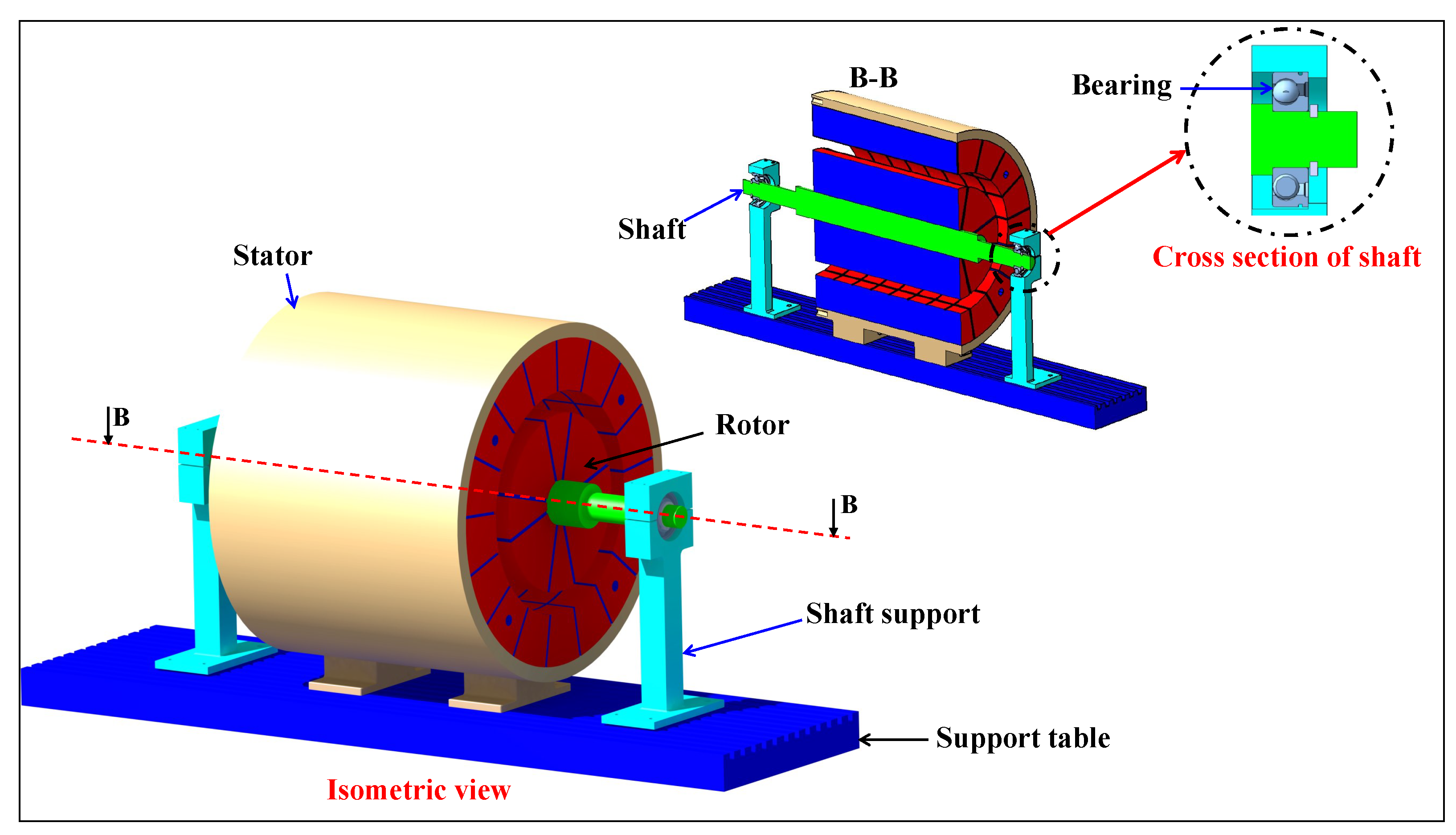
Figure 2.
The full concentric original design.
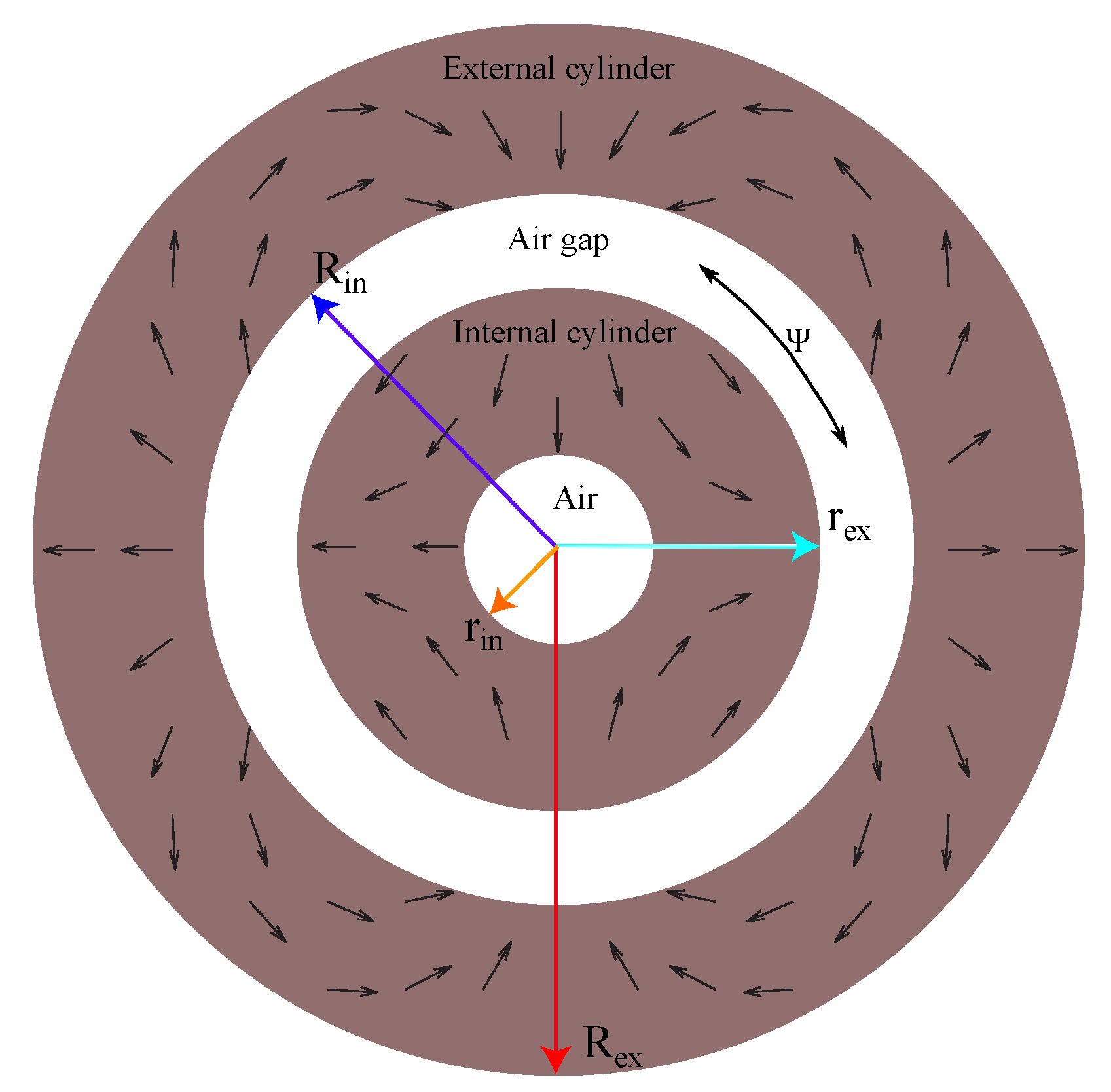
Figure 3.
The original design.
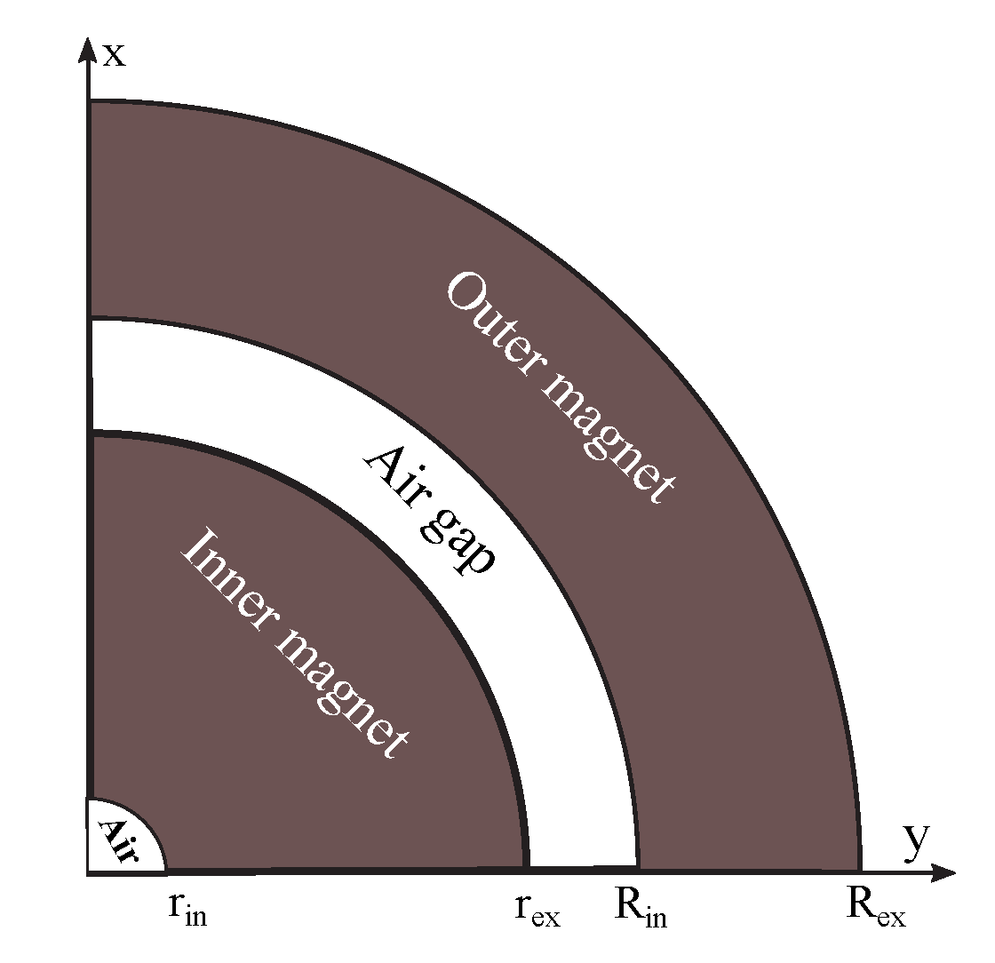
Figure 4.
The flow diagram of the designing procedure.
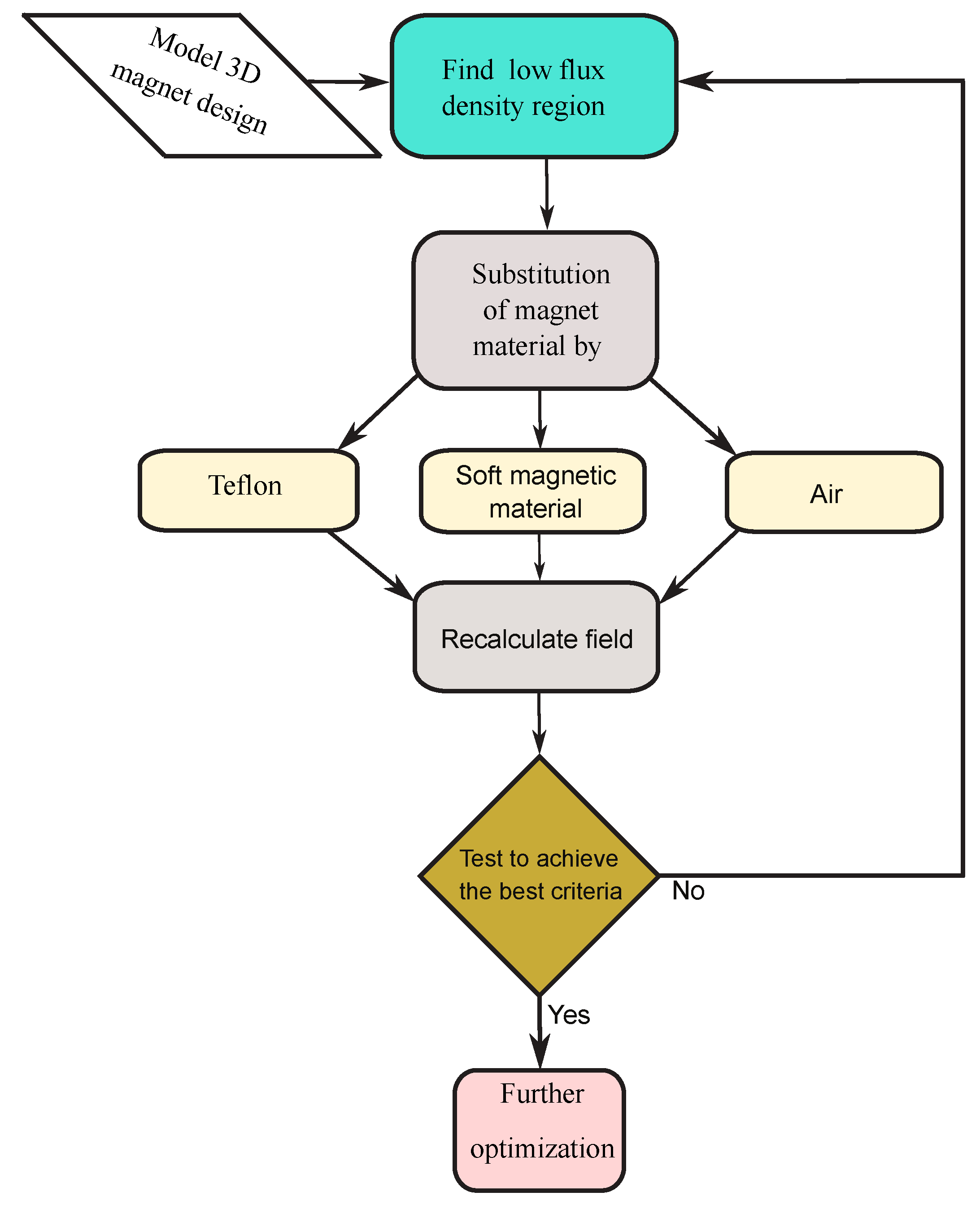
Figure 5.
The improvement schemes 1, 2, and 3: the low-carbon steel is added, magnet segments with low-carbon steel concentrators are substituted.
Figure 5.
The improvement schemes 1, 2, and 3: the low-carbon steel is added, magnet segments with low-carbon steel concentrators are substituted.
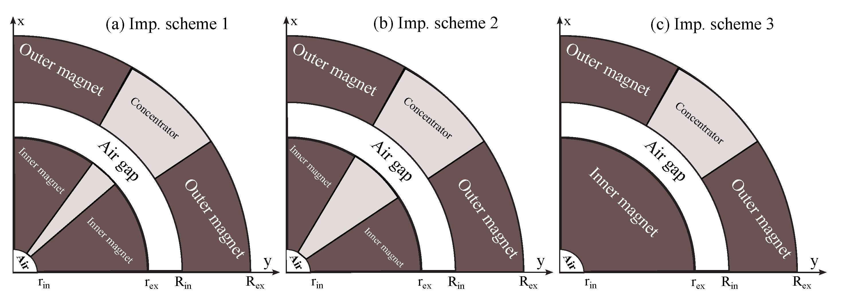
Figure 6.
The improvement schemes 4 and 5: the low-carbon steel and air are added.
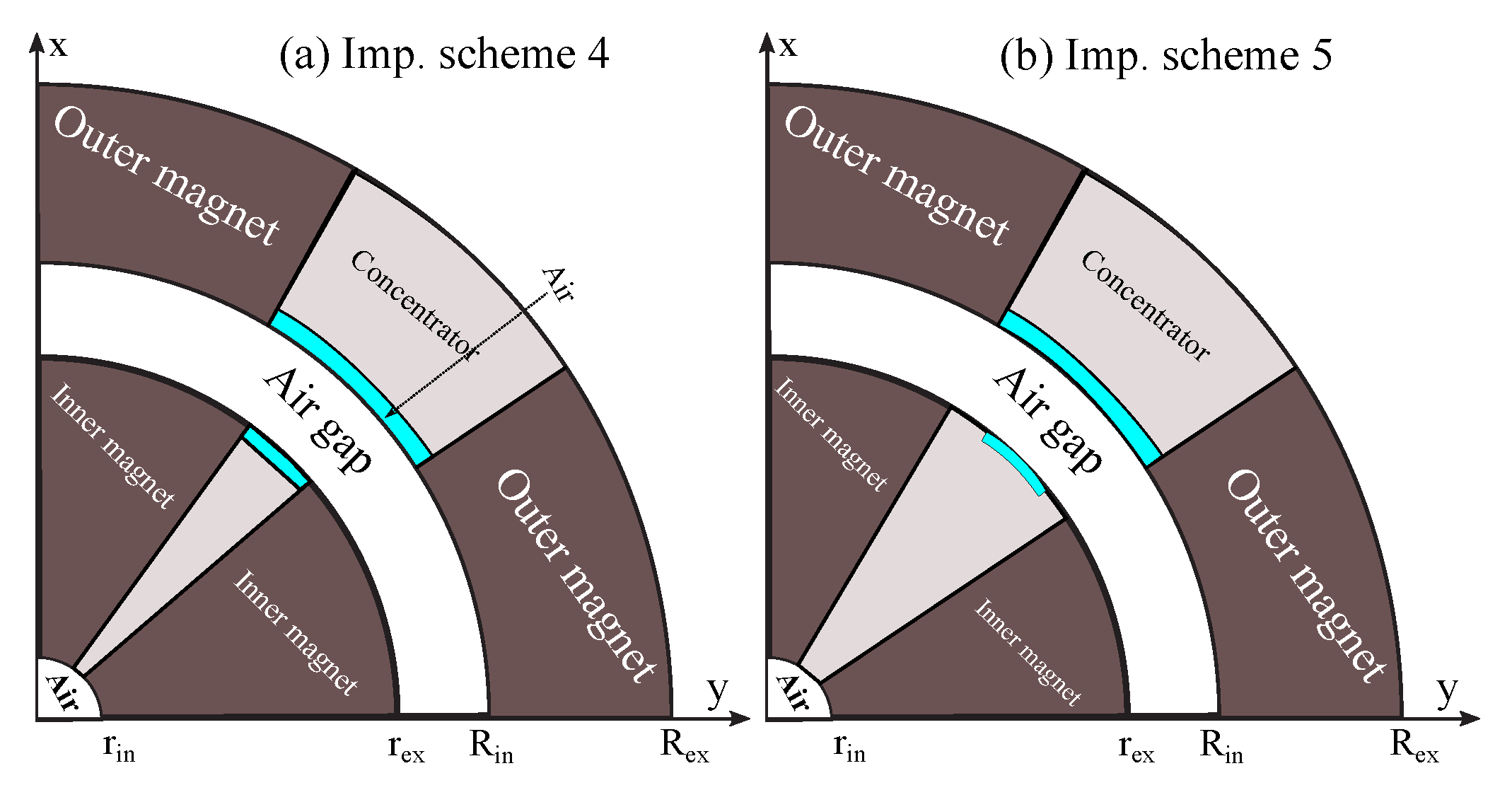
Figure 7.
The improvement scheme 6: the low-carbon steel and air are added.
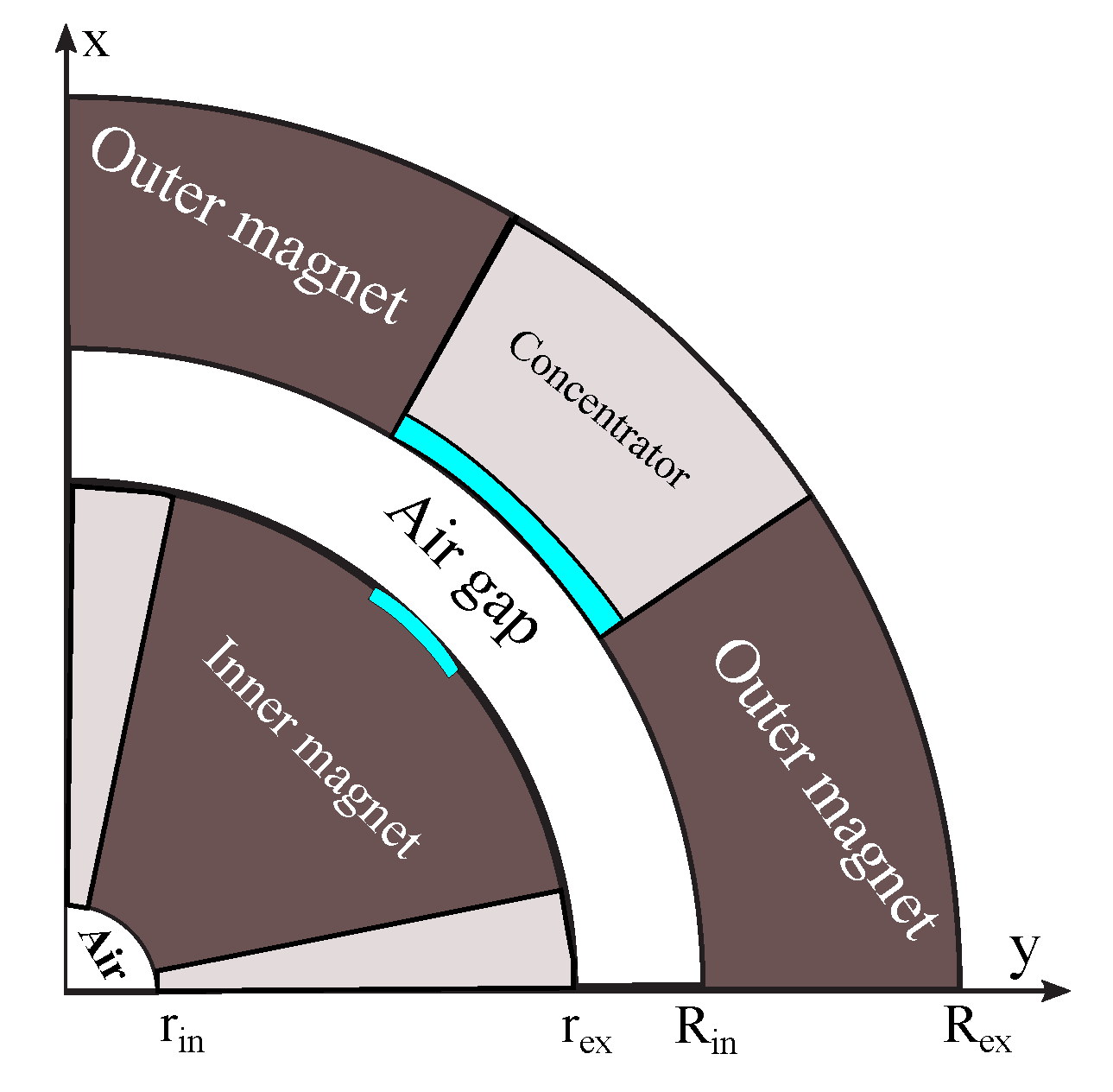
Figure 8.
The improvement schemes 7 and 8: the low-carbon steel, air, and Teflon are added.

Figure 9.
The improvement schemes 9, 10, 11, and 12: the low-carbon steel, air, and Teflon are added.
Figure 9.
The improvement schemes 9, 10, 11, and 12: the low-carbon steel, air, and Teflon are added.
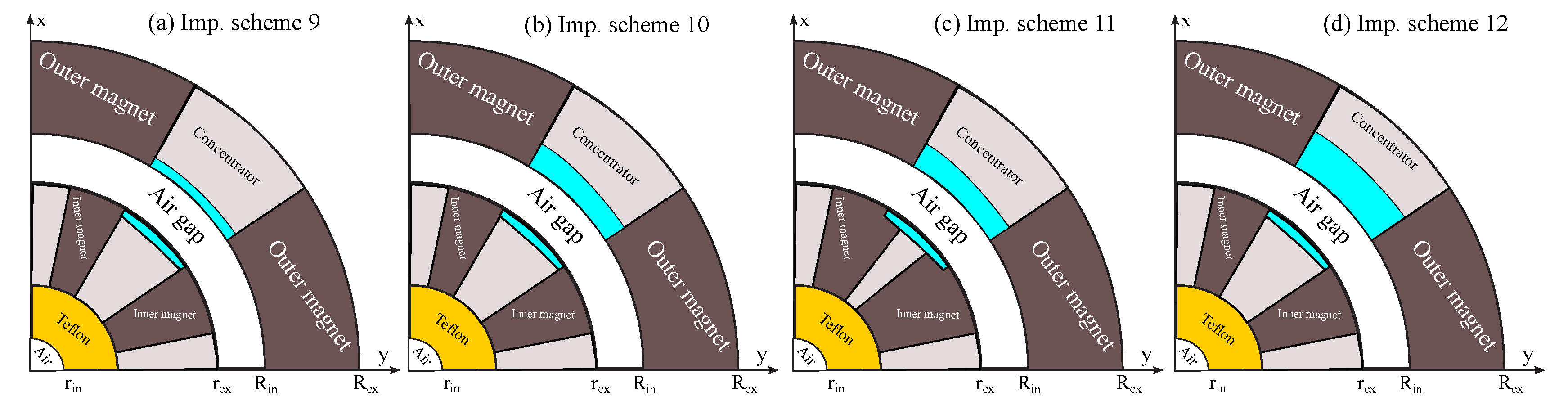
Figure 10.
Finite Element Method procedure.
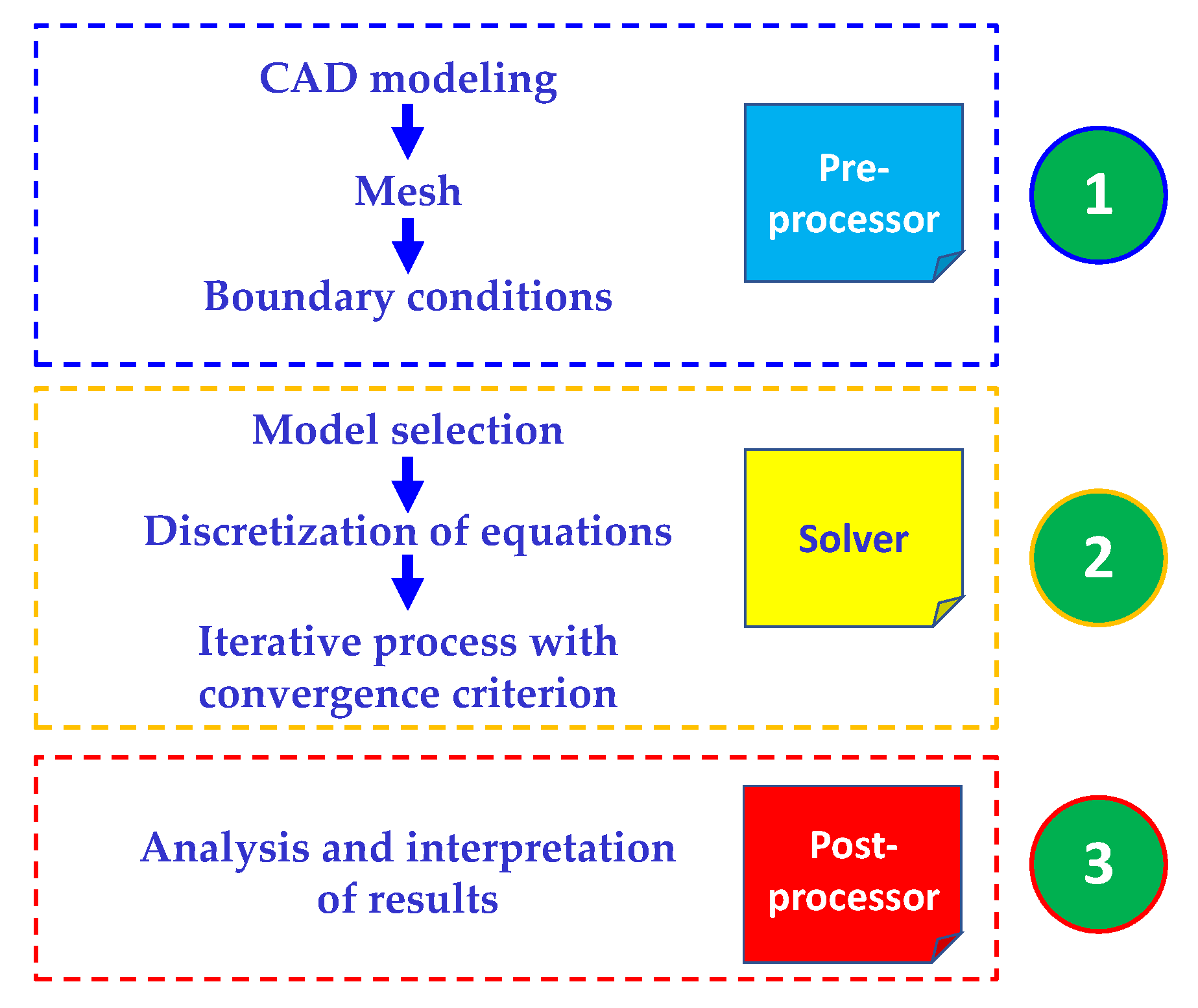
Figure 11.
Flux density of magnets of Four pole magnet design (3D simulation).
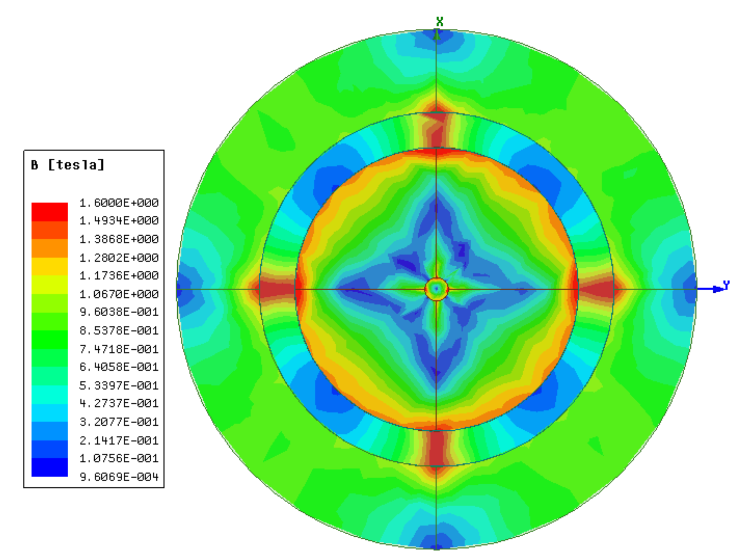
Figure 12.
Results in 3D simulation of the original design.
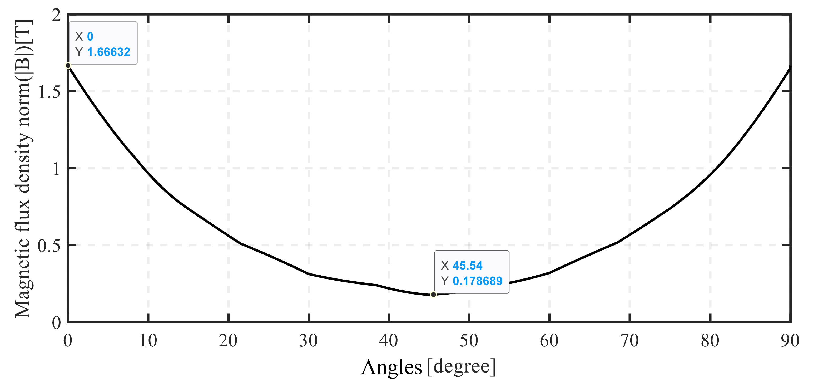
Figure 13.
Flux density of magnets of the improvement schemes 1, 2, 3 (3D simulation).
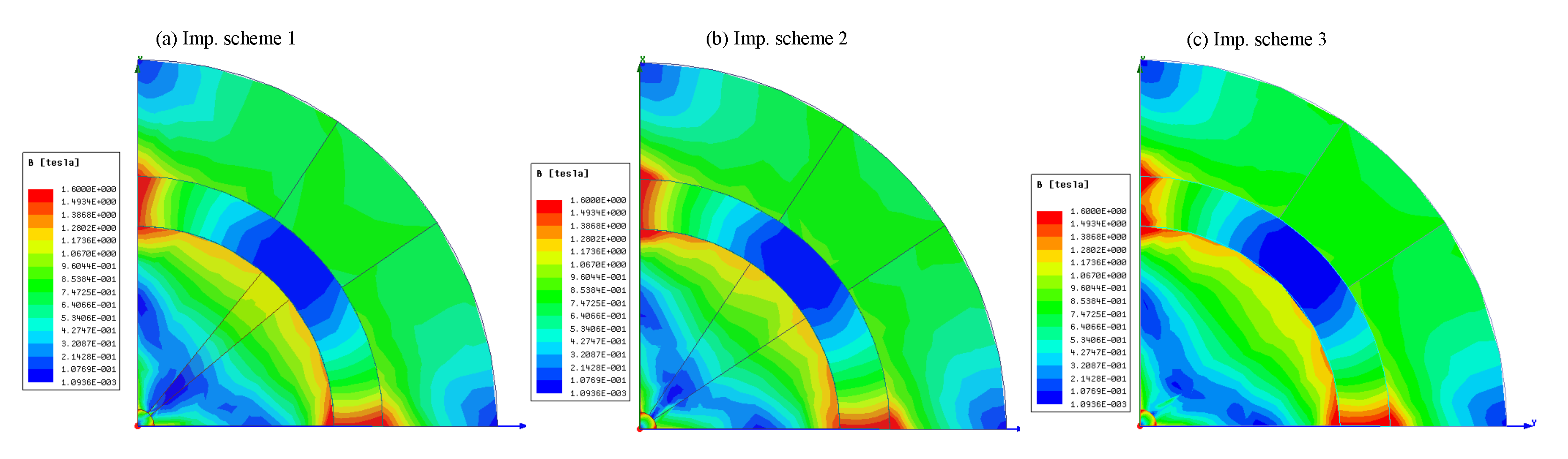
Figure 14.
Flux density of magnets of the improvement scheme 4 and 5 (3D simulation).
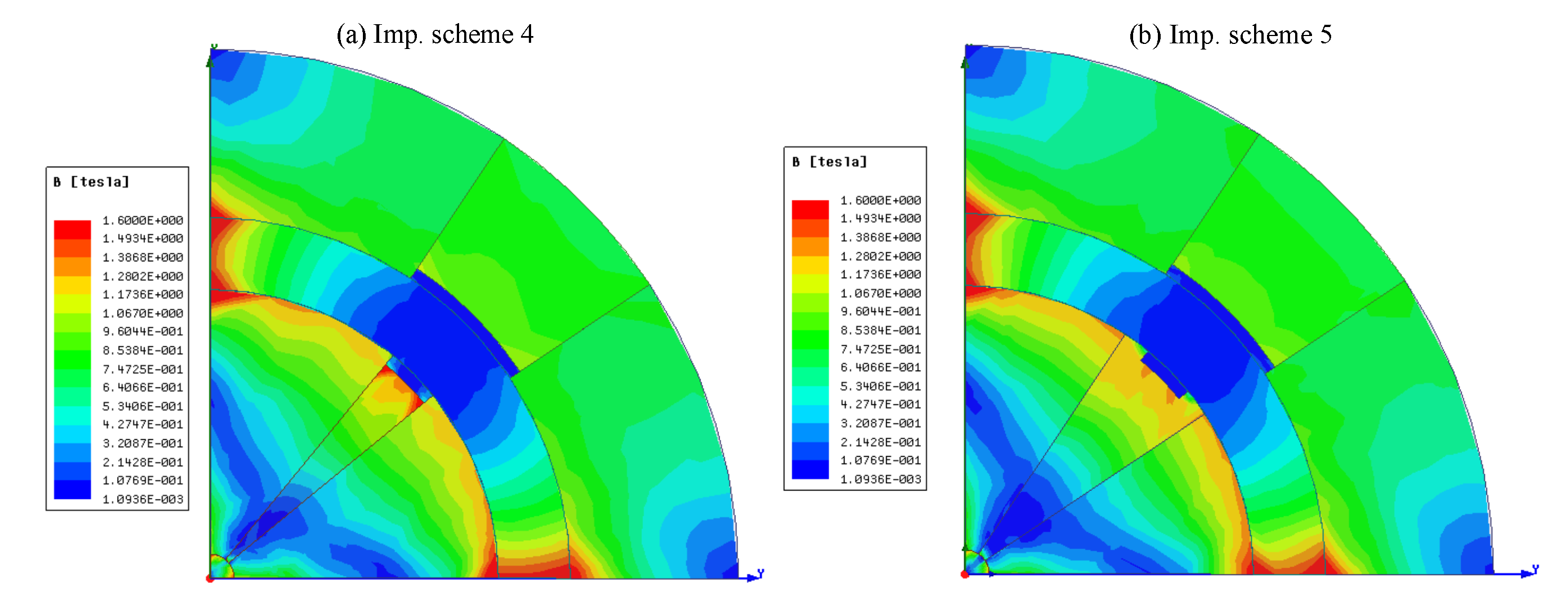
Figure 15.
Flux density of magnets of the improvement scheme 6 (3D simulation).
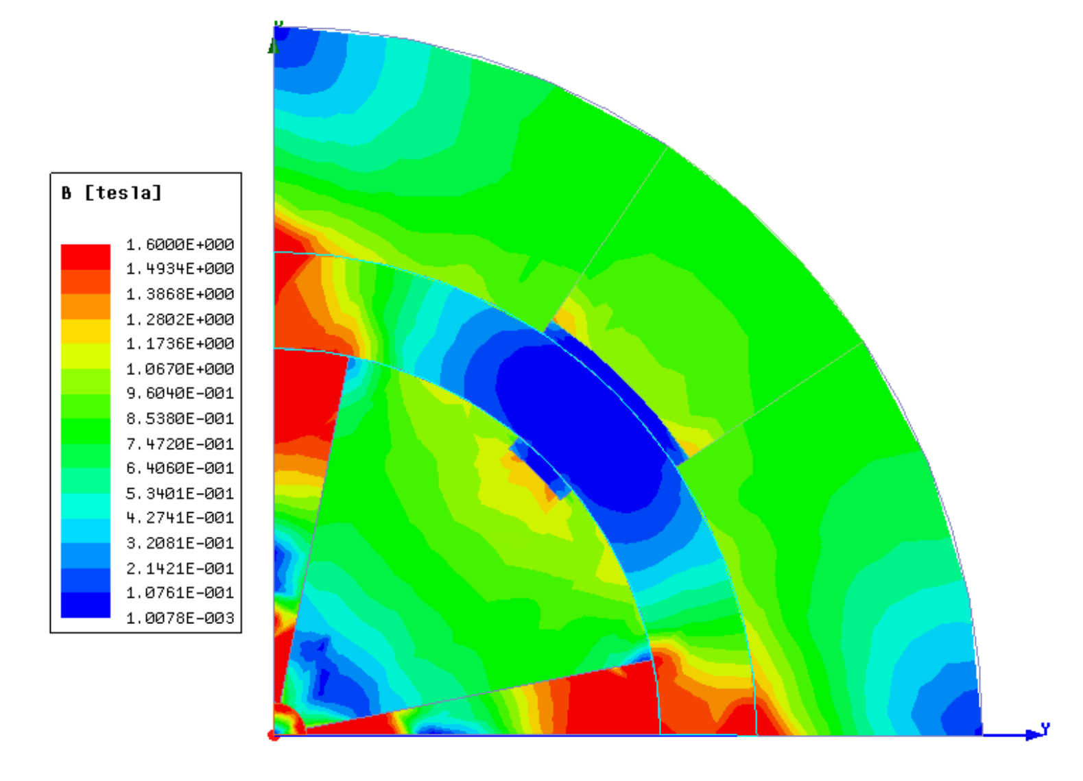
Figure 16.
Flux density of magnets of the improvement schemes 7 and 8 (3D simulation).

Figure 17.
Flux density of magnets of the improvement scheme 9, 10, 11, and 12 (3D simulation).
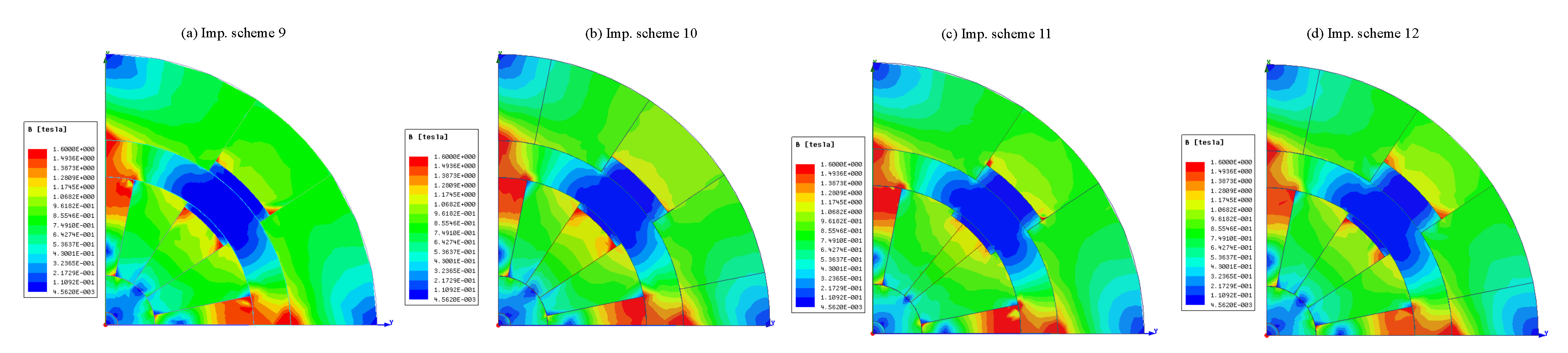
Figure 18.
The flux density as a function of angle in the middle of the air gap for the models of the improvement schemes.
Figure 18.
The flux density as a function of angle in the middle of the air gap for the models of the improvement schemes.
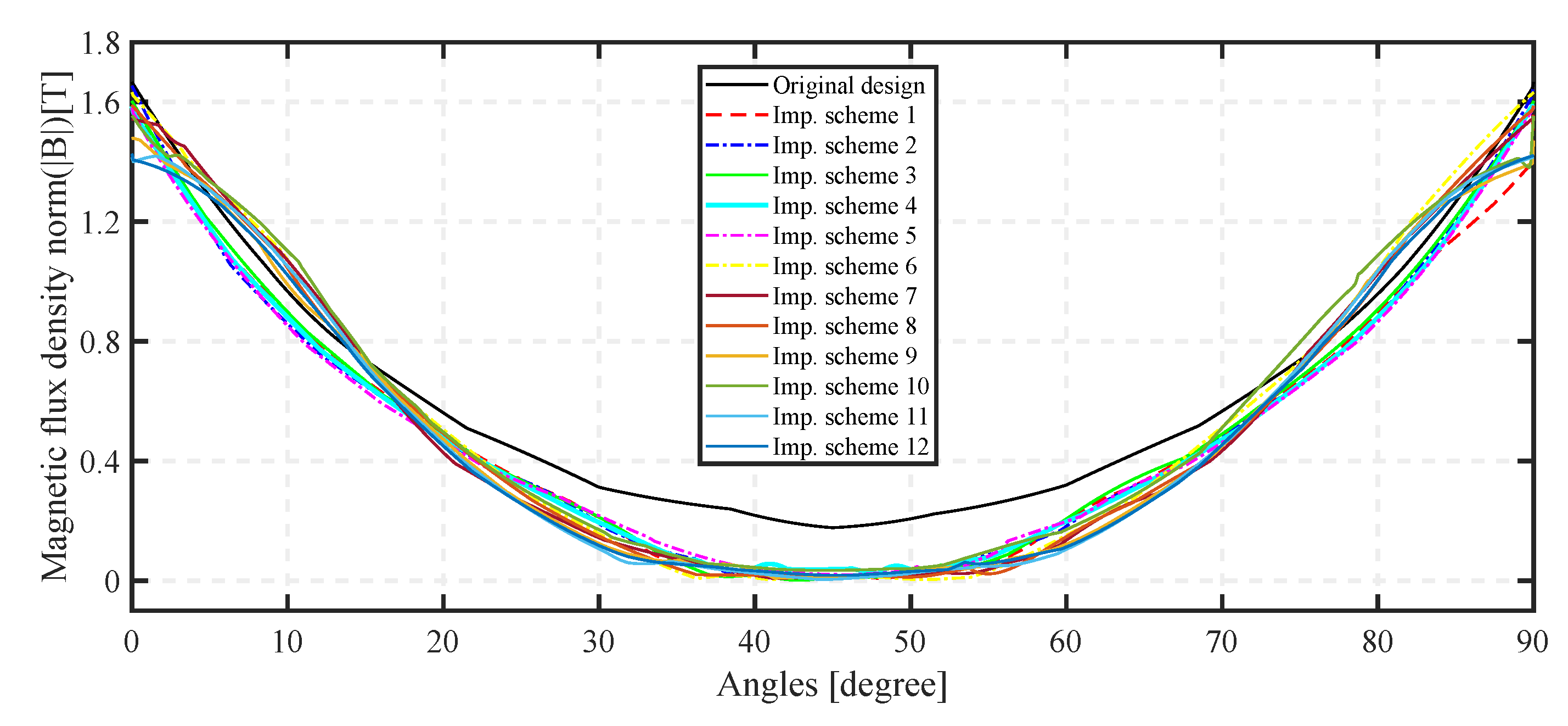
Figure 19.
Histograms comparing the 12 improvement configurations.
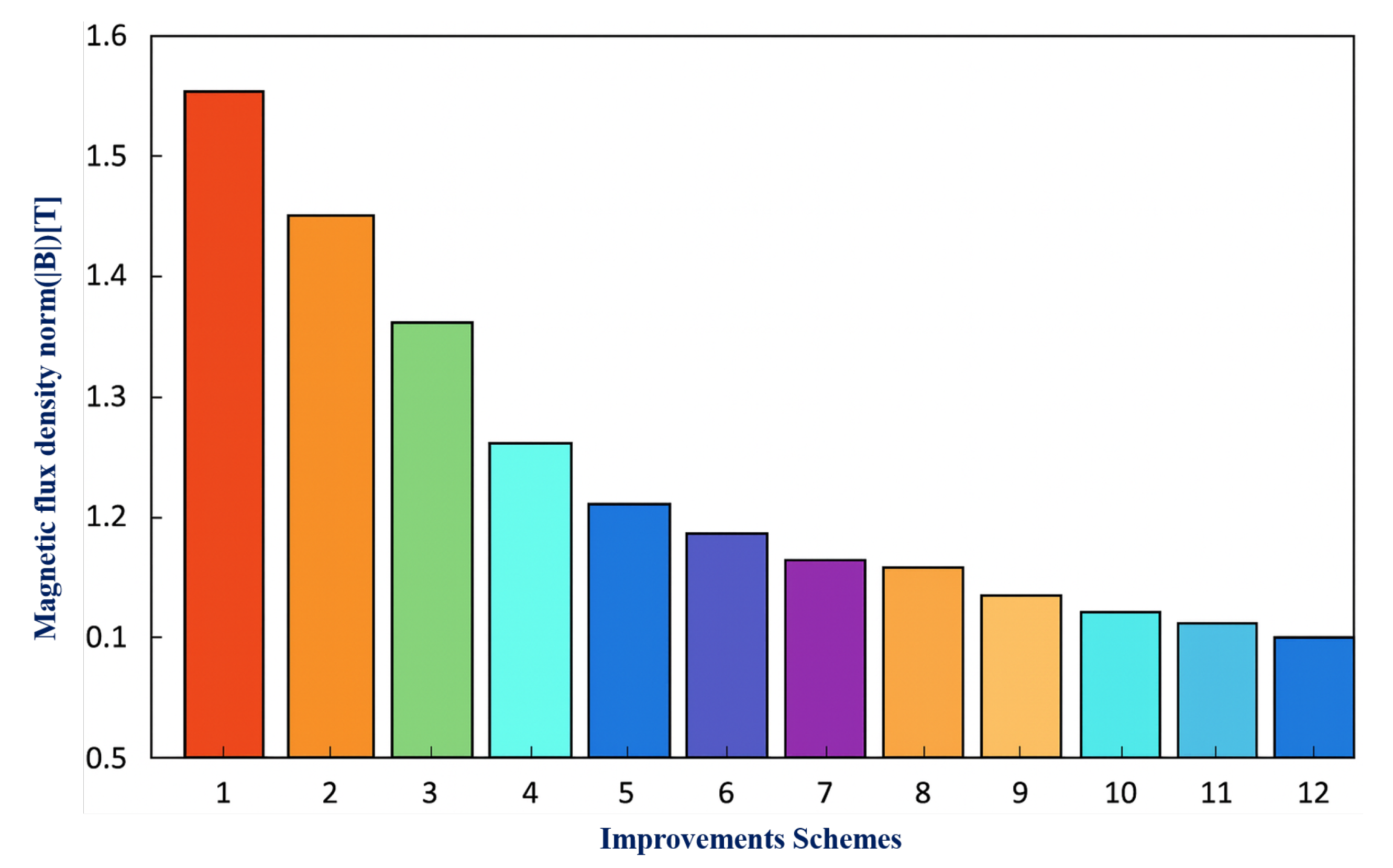

Table 1.
NdFeB Permanent Magnet Characteristics.
| Parameter | Value |
|---|---|
| Remanence[T] | 1.44 |
| Coercivity[kA/m] | 836 |
| Relative permeability [-] | 1.04457 |
| Bulk conductivity [S/m] | 265000 |
| Magnitude [T] | -837999.9999 |
Disclaimer/Publisher’s Note: The statements, opinions and data contained in all publications are solely those of the individual author(s) and contributor(s) and not of MDPI and/or the editor(s). MDPI and/or the editor(s) disclaim responsibility for any injury to people or property resulting from any ideas, methods, instructions or products referred to in the content. |
© 2025 by the authors. Licensee MDPI, Basel, Switzerland. This article is an open access article distributed under the terms and conditions of the Creative Commons Attribution (CC BY) license (http://creativecommons.org/licenses/by/4.0/).
Copyright: This open access article is published under a Creative Commons CC BY 4.0 license, which permit the free download, distribution, and reuse, provided that the author and preprint are cited in any reuse.


