Submitted:
14 November 2025
Posted:
14 November 2025
You are already at the latest version
Abstract
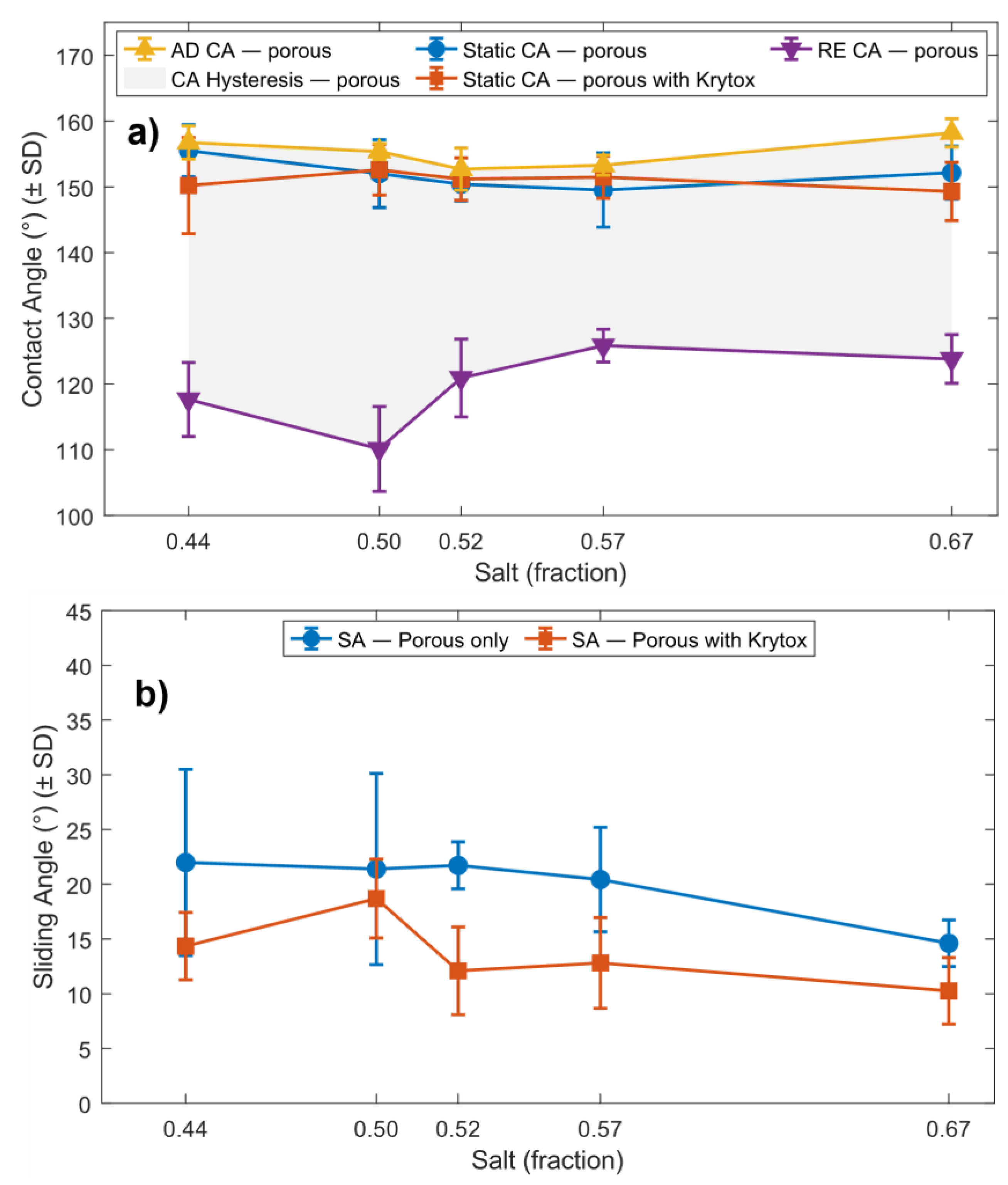
Superhydrophobic micropillar surfaces, inspired by the lotus leaf, have been extensively studied over the past two decades for their self-cleaning, anti-friction, anti-icing, and anti-corrosion properties. In this study, we introduce a simple and effective method for introducing porosity into polydimethylsiloxane (PDMS) micropillar arrays using salt templating. We then evaluate the wetting behaviour of these surfaces before and after infusion with perfluoropolyether (PFPE) oil. Apparent contact angle and sliding angle were measured relative to a non-porous control surface. Across five porous variants, the contact angle decreased by approximately 5° (from 157° to 152° on average), while the sliding angle increased by about 3.5° (from 16.5° to 20° on average). Following PFPE infusion, the porous arrays exhibited reduced sliding angles while maintaining superhydrophobicity. These results indicate that introducing porosity slightly reduces water repellency and droplet mobility, whereas PFPE infusion restores mobility while preserving high water repellency. The change in wettability following PFPE infusion highlights the potential of these surfaces to function as robust, self-cleaning materials.
Keywords:
1. Introduction
2. Materials and Methods
2.1. Materials
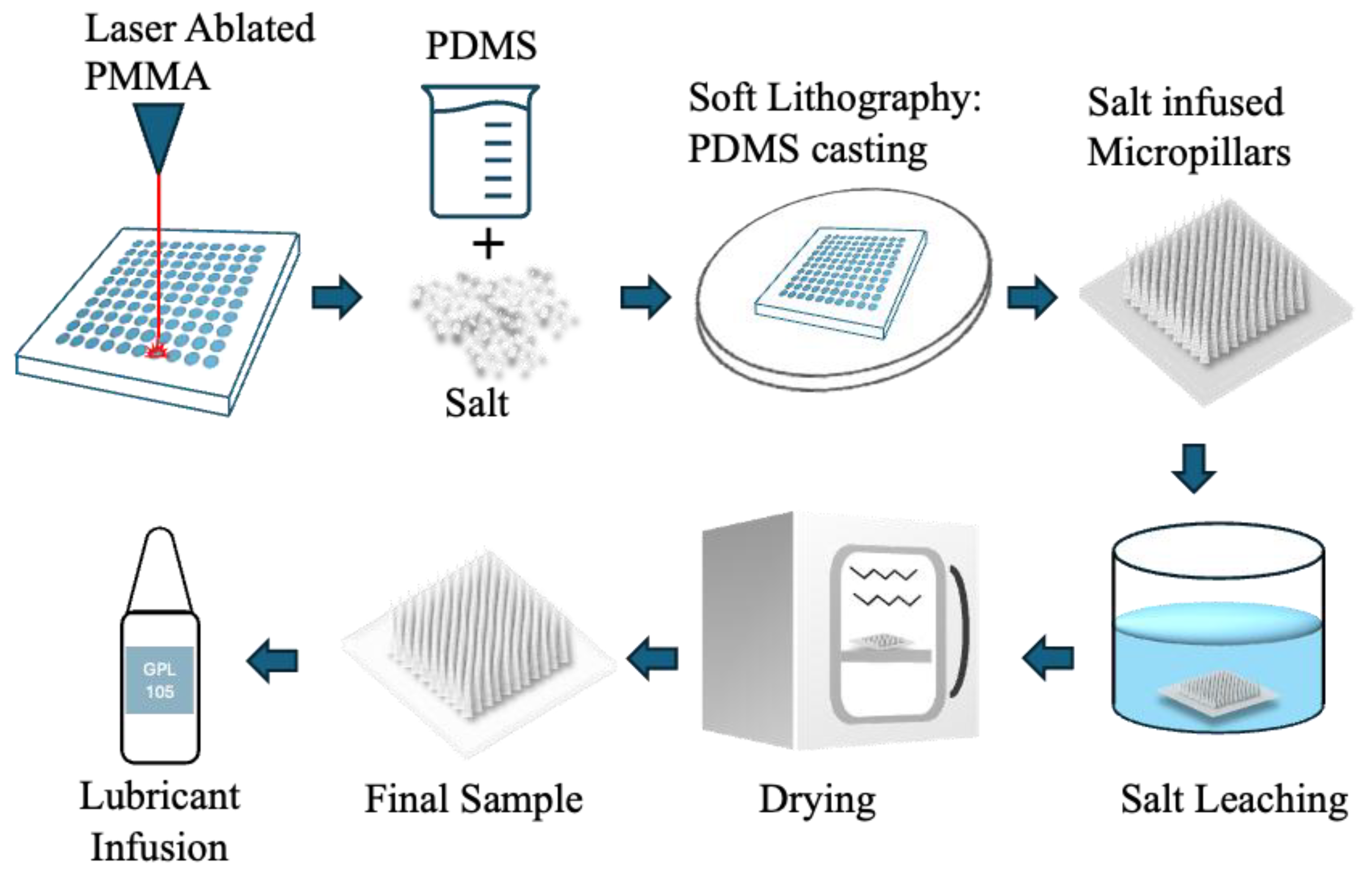
2.2. Fabrication of Micropillar Moulds
2.3. Preparation of Porous PDMS Micropillars
2.4. Salt Leaching and Drying
2.5. Liquid Infusion
2.6. Surface Characterisation
2.7. Wettability Characterisation
3. Results
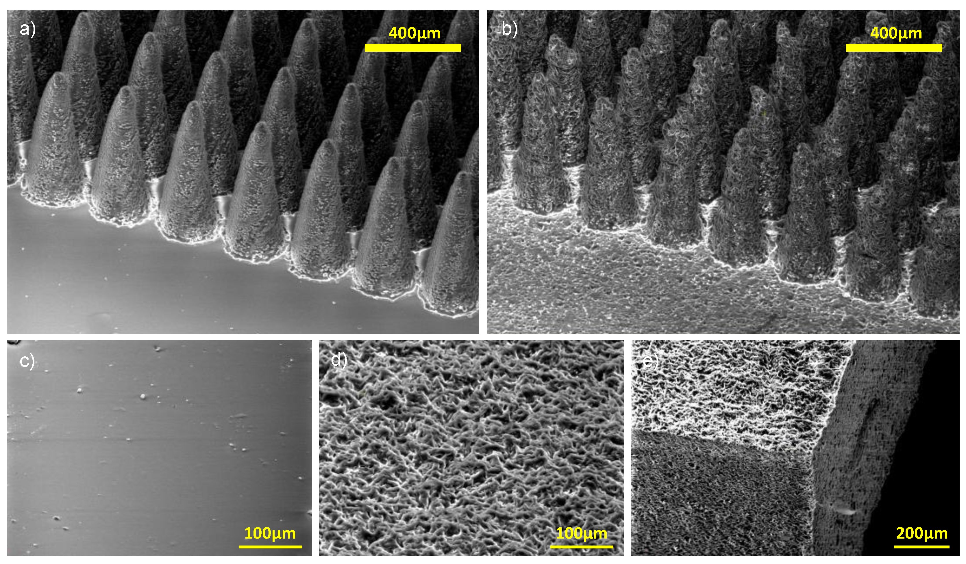
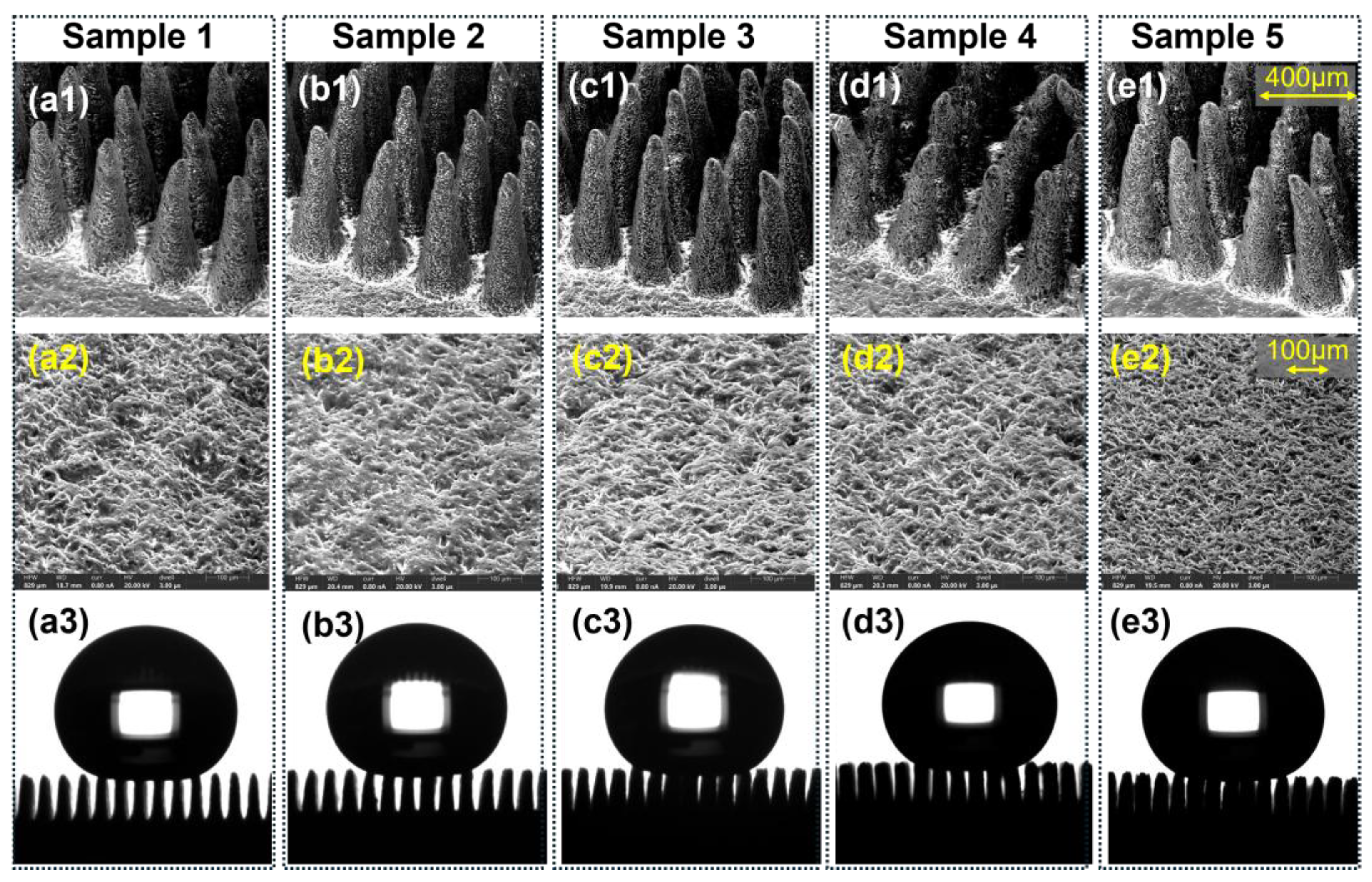
3.1. Geometrical Characterisation
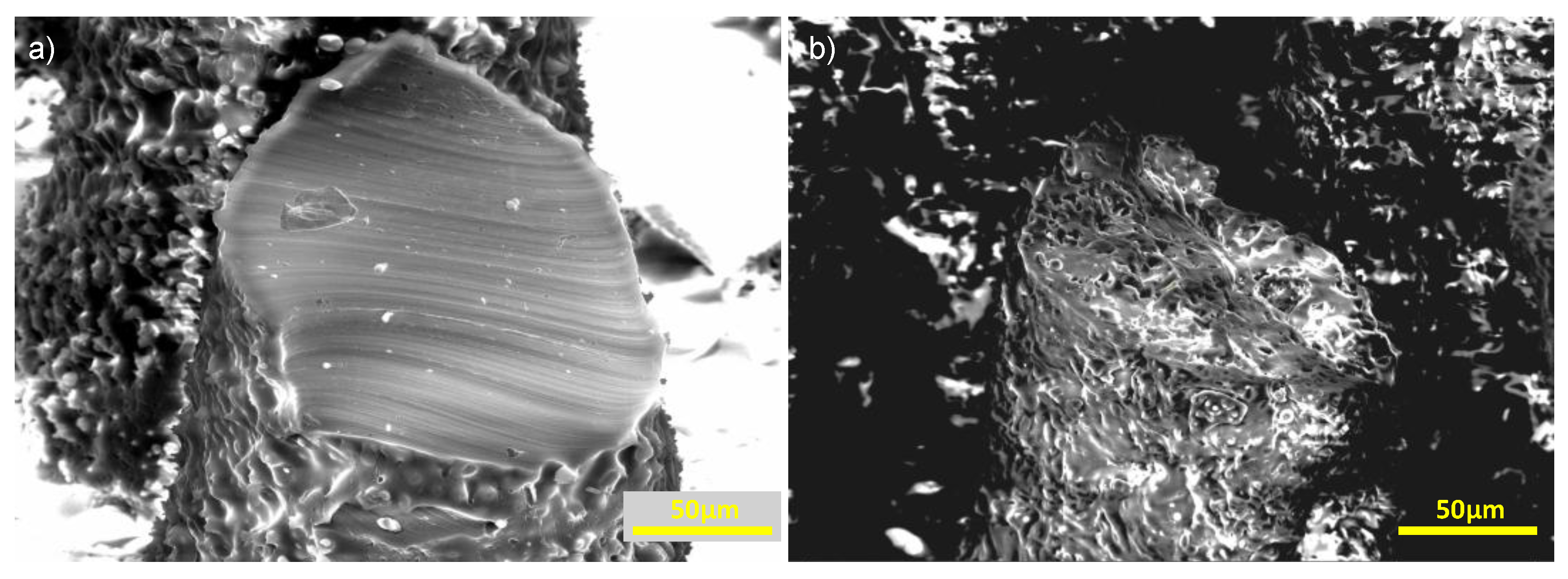
3.2. Characterisation of Surface Porosity on Plain Surfaces
3.3. Surface Wettability Characterisation
3.3.1. Wettability of Porous Micropillars
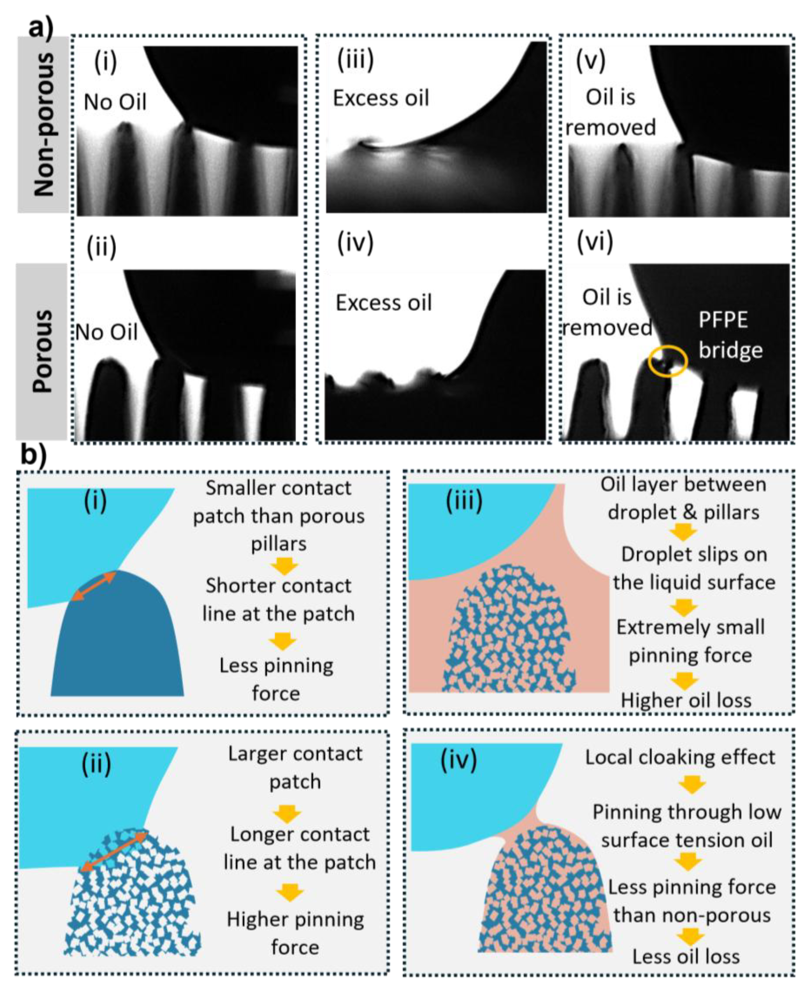
3.4. Oil Infusion on Porous Structures
4. Conclusions
Author Contributions
Funding
Data Availability Statement
Acknowledgments
Conflicts of Interest
References
- Howell, C.; Grinthal, A.; Sunny, S.; Aizenberg, M.; Aizenberg, J. Designing Liquid-Infused Surfaces for Medical Applications: A Review. Adv Mater 2018, 30. doi:ARTN 1802724. [Google Scholar] [CrossRef]
- Yuen, P.K.; Su, H.; Goral, V.N.; Fink, K.A. Three-dimensional interconnected microporous poly(dimethylsiloxane) microfluidic devices. Lab Chip 2011, 11, 1541–1544. [Google Scholar] [CrossRef] [PubMed]
- Nosonovsky, M.; Bhushan, B. Why re-entrant surface topography is needed for robust oleophobicity. Philos T R Soc A 2016, 374. doi:ARTN 20160185. [Google Scholar] [CrossRef]
- Vu, H.H.; Nguyen, N.T.; Kashaninejad, N. Re-Entrant Microstructures for Robust Liquid Repellent Surfaces. Adv Mater Technol-Us 2023, 8. [Google Scholar] [CrossRef]
- Butt, H.J.; Roisman, I.V.; Brinkmann, M.; Papadopoulos, P.; Vollmer, D.; Semprebon, C. Characterization of super liquid-repellent surfaces. Curr Opin Colloid In 2014, 19, 343–354. [Google Scholar] [CrossRef]
- Lai, Y.J.; Oh, P.C.; Chew, T.L.; Ahmad, A.L. Surface Repellency beyond Hydrophobicity: A Review on the Latest Innovations in Superomniphobic Surfaces. Acs Omega 2025, 10, 5172–5192. [Google Scholar] [CrossRef]
- Kashaninejad, N.; Nguyen, N.-T.; Chan, W.K. The three-phase contact line shape and eccentricity effect of anisotropic wetting on hydrophobic surfaces. Soft Matter 2013, 9, 527–535. [Google Scholar] [CrossRef]
- Kashaninejad, N.; Nguyen, N.-T.; Chan, W.K. Engineering Micropatterned Surfaces for Controlling the Evaporation Process of Sessile Droplets. Technologies 2020, 8. [Google Scholar] [CrossRef]
- Li, S.P.; Zhang, J.Q.; He, J.; Liu, W.P.; Wang, Y.H.; Huang, Z.J.; Pang, H.; Chen, Y.W. Functional PDMS Elastomers: Bulk Composites, Surface Engineering, and Precision Fabrication. Adv Sci 2023, 10. [Google Scholar] [CrossRef]
- De Saram, P.; Nguyen, N.T.; Kashaninejad, N. Scalable Fabrication of Height-Variable Microstructures with a Revised Wetting Model. Adv Eng Mater 2025. [Google Scholar] [CrossRef]
- De Saram, P.; Nguyen, N.T.; Jamali, S.; Kashaninejad, N. Micropillars in Cell Mechanobiology: Design, Fabrication, Characterization, and Biosensing Applications. Small Sci 2025, 5. [Google Scholar] [CrossRef]
- Lima, R.A. The Impact of Polydimethylsiloxane (PDMS) in Engineering: Recent Advances and Applications. Fluids 2025, 10. doi:ARTN 41. [Google Scholar] [CrossRef]
- Elma, M.; Yacou, C.; Wang, D.K.; Smart, S.; da Costa, J.C.D. Microporous Silica Based Membranes for Desalination. Water-Sui 2012, 4, 629–649. [Google Scholar] [CrossRef]
- Agonafer, D.D.; Lee, H.; Vasquez, P.A.; Won, Y.; Jung, K.W.; Lingamneni, S.; Ma, B.J.; Shan, L.; Shuai, S.; Du, Z.C.; et al. Porous micropillar structures for retaining low surface tension liquids. J Colloid Interf Sci 2018, 514, 316–327. [Google Scholar] [CrossRef]
- Zheng, D.Y.; Choi, C.H.; Zhao, X.; Sun, G.Y. Facile fabrication of sponge-like porous micropillar arrays an electrochemical process. Nanoscale 2020, 12, 10565–10572. [Google Scholar] [CrossRef]
- González-Rivera, J.; Iglio, R.; Barillaro, G.; Duce, C.; Tinè, M.R. Structural and Thermoanalytical Characterization of 3D Porous PDMS Foam Materials: The Effect of Impurities Derived from a Sugar Templating Process. Polymers-Basel 2018, 10. doi:ARTN 616. [Google Scholar] [CrossRef] [PubMed]
- Li, Q.; Duan, T.T.; Shao, J.; Yu, H.B. Fabrication method for structured porous polydimethylsiloxane (PDMS). J Mater Sci 2018, 53, 11873–11882. [Google Scholar] [CrossRef]
- Liu, Y.B.; Tian, Y.; Chen, J.; Gu, H.M.; Liu, J.; Wang, R.M.; Zhang, B.L.; Zhang, H.P.; Zhang, Q.Y. Design and preparation of bioinspired slippery liquid-infused porous surfaces with anti-icing performance via delayed phase inversion process. Colloid Surface A 2020, 588. doi:ARTN 124384. [Google Scholar] [CrossRef]
- Tan, X.Q.; Zheng, J.M. A Novel Porous PDMS-AgNWs-PDMS (PAP)-Sponge-Based Capacitive Pressure Sensor. Polymers-Basel 2022, 14. doi:ARTN 1495. [Google Scholar] [CrossRef] [PubMed]
- Thurgood, P.; Baratchi, S.; Szydzik, C.; Mitchell, A.; Khoshmanesh, K. Porous PDMS structures for the storage and release of aqueous solutions into fluidic environments. Lab on a Chip 2017, 17, 2517–2527. [Google Scholar] [CrossRef] [PubMed]
- Wu, F.; Xu, J.; Wang, Z.; Jiang, J.H.; Liu, Y.X.; Zhang, N.; Zhang, K.; Chong, F.L.; Li, J.A. Functional liquid-infused PDMS sponge-based catheter with antithrombosis, antibacteria, and anti-inflammatory properties. Colloid Surface B 2023, 224. doi:ARTN 113208. [Google Scholar] [CrossRef] [PubMed]
- Zhao, X.; Li, L.X.; Li, B.C.; Zhang, J.P.; Wang, A.Q. Durable superhydrophobic/superoleophilic PDMS sponges and their applications in selective oil absorption and in plugging oil leakages. J Mater Chem A 2014, 2, 18281–18287. [Google Scholar] [CrossRef]
- Zheng, F.Y.; Li, Q.S.; Yang, P.H.; Qiu, S.H.; Mao, H.J.; Zhao, J.L. Fabrication of Ultra-Thin Micro-Porous Pdms Membrane for Cell Co-Culture in Blood Brain Barrier Model on Chip. In Proceedings of the International Conference on Solid-State Sensors, Actuators and Microsystems (Transducers), Orlando, FL, USA; 2021; pp. 279–282. [Google Scholar]
- Zhuo, Y.Z.; Wang, F.; Xiao, S.B.; He, J.Y.; Zhang, Z.L. One-Step Fabrication of Bioinspired Lubricant-Regenerable Icephobic Slippery Liquid-Infused Porous Surfaces. Acs Omega 2018, 3, 10139–10144. [Google Scholar] [CrossRef] [PubMed]
- Turco, A.; Primiceri, E.; Frigione, M.; Maruccio, G.; Malitesta, C. An innovative, fast and facile soft-template approach for the fabrication of porous PDMS for oil-water separation. J Mater Chem A 2017, 5, 23785–23793. [Google Scholar] [CrossRef]
- Lo, L.W.; Zhao, J.Y.; Aono, K.; Li, W.L.; Wen, Z.C.; Pizzella, S.; Wang, Y.; Chakrabartty, S.; Wang, C. Stretchable Sponge Electrodes for Long-Term and Motion-Artifact-Tolerant Recording of High-Quality Electrophysiologic Signals. Acs Nano 2022, 16, 11792–11801. [Google Scholar] [CrossRef]
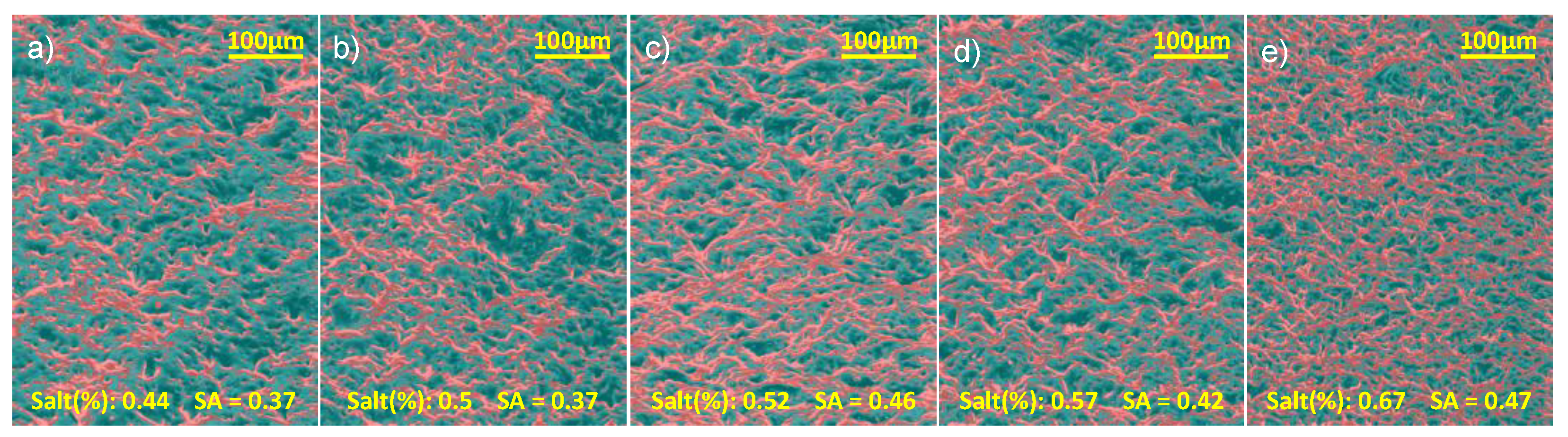

| Sample | NaCl (g) | PDMS (g) | Ratio | w/w % |
| 1 | 1.6 | 2 | 0.8:1 | 44.4% |
| 2 | 2 | 2 | 1:1 | 50% |
| 3 | 2.2 | 2 | 1.1:1 | 52.4% |
| 4 | 2.6 | 2 | 1.3:1 | 56.5% |
| 5 | 4 | 2 | 2:1 | 66.7% |
Disclaimer/Publisher’s Note: The statements, opinions and data contained in all publications are solely those of the individual author(s) and contributor(s) and not of MDPI and/or the editor(s). MDPI and/or the editor(s) disclaim responsibility for any injury to people or property resulting from any ideas, methods, instructions or products referred to in the content. |
© 2025 by the authors. Licensee MDPI, Basel, Switzerland. This article is an open access article distributed under the terms and conditions of the Creative Commons Attribution (CC BY) license (https://creativecommons.org/licenses/by/4.0/).


