Preprint
Article

This version is not peer-reviewed.

Impact of Molecular Reactive Gas Injection on Species Emitted at the Exit of a Tubular Atmospheric Pressure Plasma Jet Source

Submitted:

14 November 2025

Posted:

17 November 2025

You are already at the latest version

Abstract

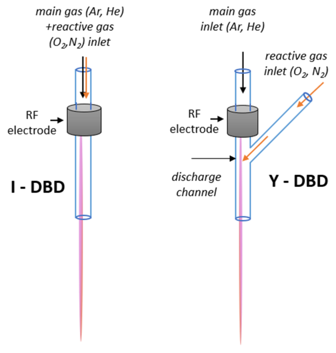
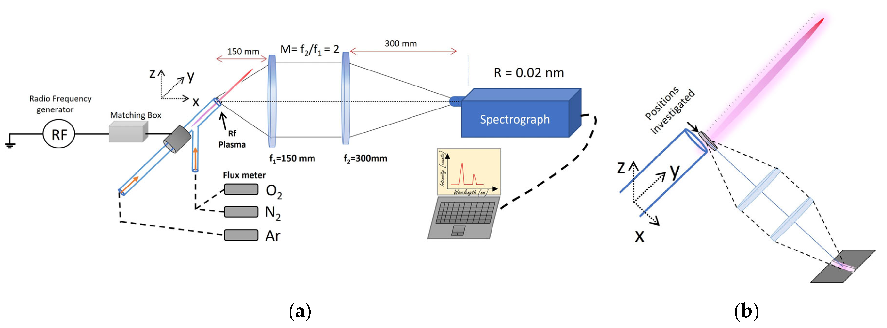
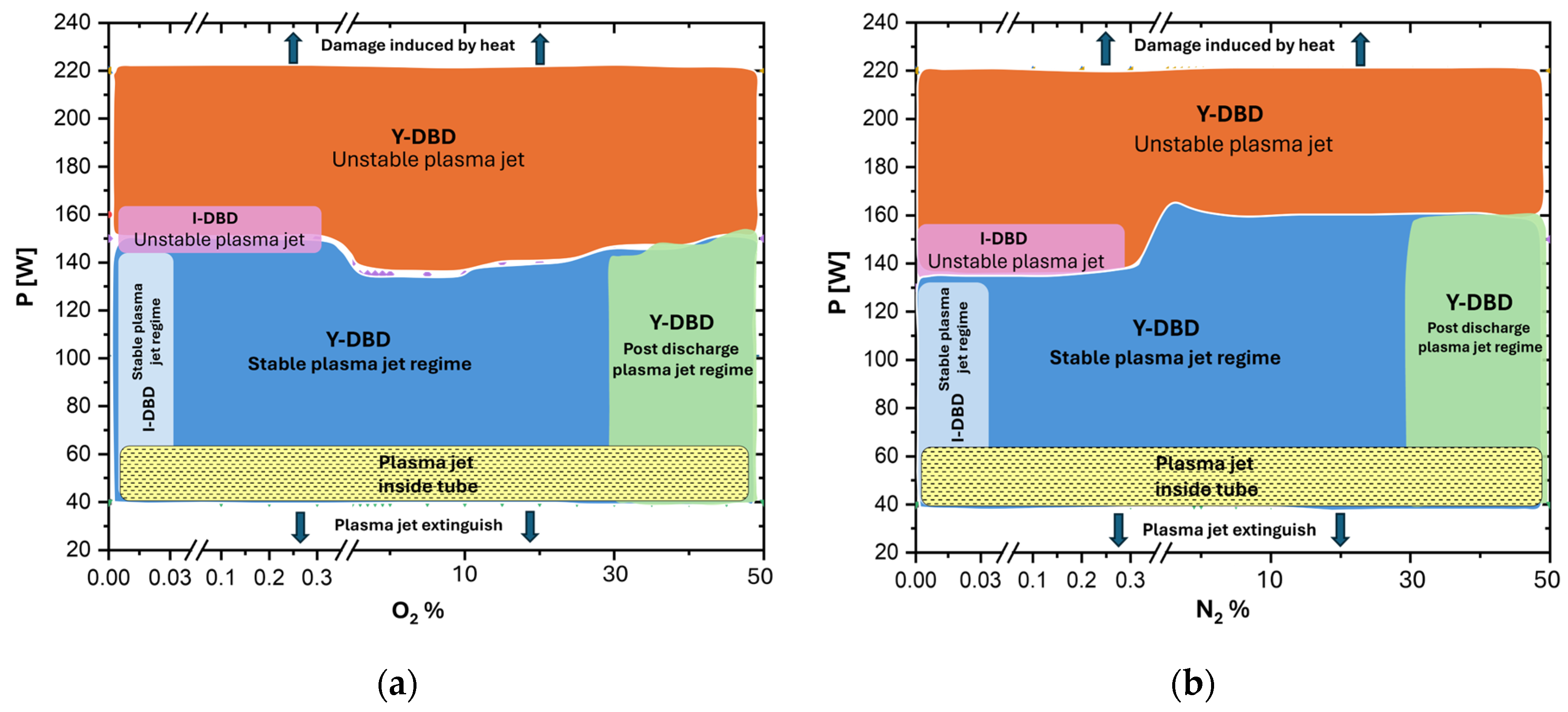
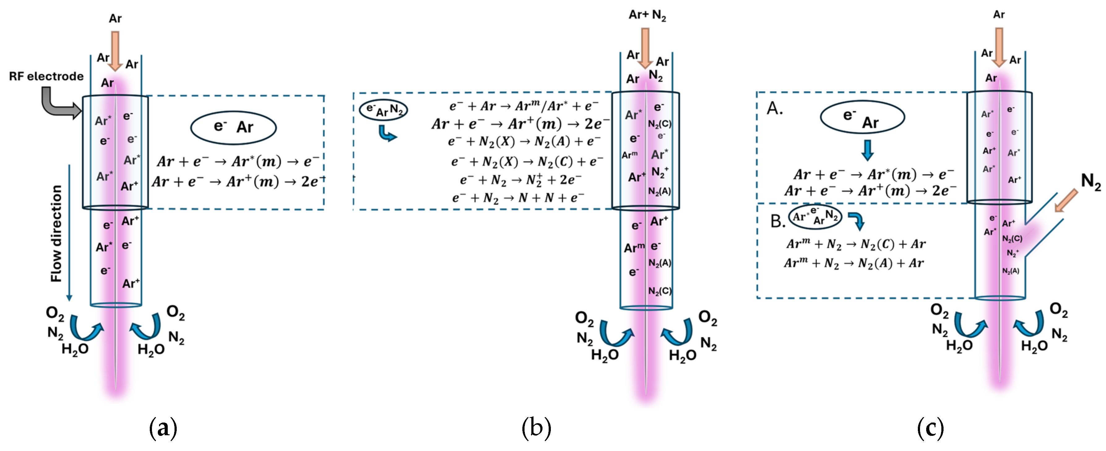
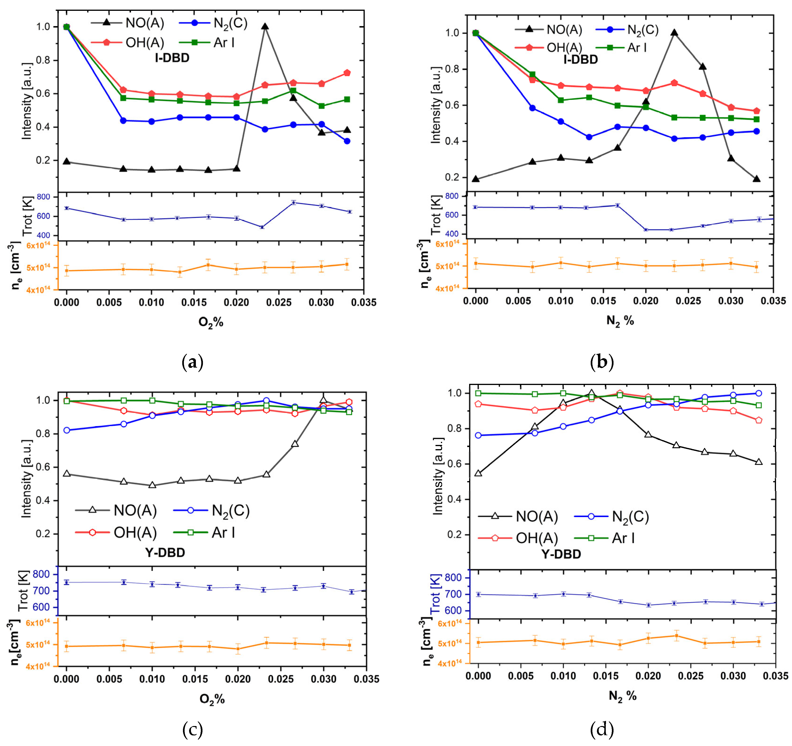
Control of reactive species generation lies at the core of atmospheric-pressure plasma processing. In this work, we investigate the capability of a cold RF argon plasma jet source to produce reactive oxygen and nitrogen species (RONS) following the injection of a molecular gas (N₂ or O₂), either premixed with the main gas (Ar) or introduced separately into an already generated Ar discharge. We show that when reactive gases are injected directly into the Ar discharge, the range of operating parameters—particularly the ratio of reactive gas to main gas—is considerably widened compared to the conventional injection through the main argon flow. The plasma characteristics at the source exit were analyzed using Optical Emission Spectroscopy (OES), including the determination of electron density, rotational temperature, and the emission intensities of plasma species such as Ar I, NO(A), OH(A), and N₂(C), for both injection types. Overall, the results show that plasmas generated using in-discharge injection are more stable and capable of sustaining enhanced production of reactive radicals such as NO(A) and OH(A), whereas injection through the main gas can be tuned to selectively enhance NO generation. These findings highlight the potential of plasma sources employing premixed or in-discharge reactive gas injection for surface treatment and for the processing of gas and liquid phases.

Keywords: 
;  ;  ;  ;  ;  ;  ;  

1. Introduction

While many applications use the thermal effects of plasmas operating at atmospheric pressure (such as plasma welding [1], melting [2], cutting [3], and so on), cold plasma processing is based on chemical effects sustained by the interaction of reactive species existing in plasma (or generated by plasma) with materials [4]. Cold atmospheric pressure plasma sources remain at the forefront of research, due to their advantages of processing various materials in solid, liquid, and gas phases [5].
The nature and the quantity of reactive species is a key element in the processing activities. There are numerous reactive species with remarkable role in different applications; among them the most well-known are: OH [6], NH [7], NO[8,9,10], O[11,12], O3 [13], ions [14], metastable [15]. It is also important to mention that the identification and quantification of plasma generated species rely on dedicated plasma diagnostics. Among these, optical emission spectroscopy (OES) is the most widely used due to its non-invasive nature and the broad availability of instrumentation. However, processing and interpreting spectral data requires a high level of expertise. General information on the use of OES as a diagnostic tool for atmospheric pressure plasmas can be found in [16], while examples related to specific applications, such as food technology [17] or surface processing [18] illustrate its practical relevance across various plasma systems.
A major problem in modern high-power laser systems is the contamination of optics, with mirrors being particularly affected by carbonaceous deposits, which can lead to increased absorption, local heating, and their dielectric coating degradation [19,20]. Therefore, the ability to remove the contaminated mirror surface without damaging the underlying coating is very important for maintaining optical performance for a long time. Traditional cleaning methods, such as mechanical polishing, may be too aggressive for sensitive optical coatings. In this context the use of chemically reactive species RONS generated by cold atmospheric pressure plasmas jets represents an effective and controllable alternative for the removal of carbon contamination [9,10]. Atmospheric pressure plasma cleaning was also proposed as a support for the wall maintenance and diagnostic mirrors in fusion technology [21,22]. These plasmas have also been investigated for liquid decontamination, demonstrating a high efficiency as reported in [23,24]. Also, the plasma jet was applied for the in liquid functionalization of nanomaterials, like carbon nanowalls [25] or nanocellulose [26] dispersed in water, demonstrating its ability to introduce chemical modification through plasma-liquid interaction.
One of the technical problems in the reactive species generation by atmospheric pressure plasma sources is related to gas injection procedures, where various constraints should be fulfilled simultaneously. The stationary atmospheric pressure cold plasmas are mostly generated in flowing atomic gases, such as He [27,28] and Ar [29,30]. These gases are suitable because they prevent the discharge from transitioning into a thermal arc regime. First, unlike molecular gases, discharges in atomic gases require less power since rotational, vibrational and dissociation processes are absent [31]. Second, they provide a cooling effect through efficient heat transfer from the electrodes, supported by fast gas flow and the high thermal conductivity of gases such as helium. Still, the creation of specific reactive species, requires the presence of molecular gases for example, oxygen, nitrogen, hydrocarbon, fluorinated gases, etc. Sometimes it is enough for gas molecules (O2, N2, H2O) to be taken during plasma expansion from the environment [32]. Contrary, in those cases where such gases are undesired, an inert gas curtain can be applied [33,34,35]. The injecting of molecular gas downstream of the discharge is also possible, with the disadvantages of non-isotropic mixing and limited excitation transfer from the species carrying energy from the discharge (ions, metastable species).
The most desired would be the injection of the molecular gas in a controlled manner and in the discharge. The common way is the admixing of the reactive gas with the main inert gas sustaining the discharge. This approach is illustrated in Figure 1 (left). Nevertheless, this may lead to plasma extinction, which can be prevented by the increase of applied power, thus raising the risk of transition to arc. The consequence is that only limited amounts of reactive gases can be added while keeping the discharge running and cool. For example, the literature reports for the ratio of reactive to main gas, depending on the plasma source and application, values between 1-2 % O2 and/ or N2 in sources using He as the main gas [12,36] and values between 0.2 and 1.5 % in sources using Ar as the main gas [37,38]. The increasing of this ratio is in high demand for plasma processing technologies especially in biomedical applications where the RONS species generation plays a significant role [39].
Herewith we present an atmospheric pressure DBD plasma jet source, capable of working in cold regime with high amounts of molecular reactive gases (N2 or O2). This is made possible by the injection of the reactive gas separately from the main inert gas, downstream the active RF electrode into the middle of discharge channel. This approach is illustrated in Figure 1 (right). Accordingly, the discharge is sustained in the main atomic gas upstream of the injection point, allowing the maintaining of discharge even at high amounts of injected reactive gases. Based on the similarity of the injection geometries shown in Figure 1 with the capital letters “I” and “Y”, we refer further to the respective plasma sources as I-DBD and Y-DBD. The design details of the two sources are provided in the experimental section. In the results section, their operating domains in terms of power and gas flow rate are compared, highlighting the superiority of Y-DBD in respect to the working parameter ranges. Additionally, the emission intensity of the reactive species (NO, OH, and N2) and the plasma characteristics (electrons density, rotational and vibrational temperatures) were analyzed as a function of the amount of molecular gas injected. This analysis was performed using OES, considering the spectra acquired near the tube exit. The results show that the behavior of the species is consistent with the main mechanisms governing their formation and excitation in atomic plasmas mixed with molecular gases. Based on these findings, we recommend recipes that optimize the production of NO and OH radicals.

2. Experimental Details and Methods

The schematic view of the experimental setup used for the plasma investigations is shown in Figure 2a. Two main parts are noticed, one of them dedicated to plasma operation and control, the other one dedicated to plasma investigations.

2.1. Plasma Generation and Control

The system for plasma generation and control consists of the plasma source, the power and gas feeding arrangements (Figure 2). The sources used in this work are based on one electrode RF discharge as described in our previous work Teodorescu et al. [29]. The discharge is ignited in a glass tube of 6 mm outer diameter, in flowing Ar gas, with one annular electrode placed on the tube. The grounded electrode is physically missing; its presence is substituted by the external bodies distributed in the space around the plasma source. We have shown that this configuration produces a stable one filament discharge surrounded by a diffuse plasma region; the filament develops inside the tube starting with the electrode position and extends outside the tube as a long (up to 5 cm) thin plasma jet. This configuration (denoted here as I-DBD) was modified with a lateral tube joining the main tube downstream the electrode position (Y-DBD, as detailed in Figure 1). We found out that this modification did not affect the operation of the source in one filament stable mode. For both source types the plasma is sustained at atmospheric pressure by a 13.56 MHz RF power generator (CESAR, Advanced Energy), operated in power control mode, and an adequate matching box (AMV-1000-EN, ADTEC). The operation of the sources was investigated in the 30-220 W range; with the applied power limited to a maximum of 220 W to prevent source damage. For gas delivery mass flow controllers (Bronkhorst) were used. Argon was used as main gas, at a mass flow rate of 3000 sccm. Oxygen or Nitrogen were used as reactive gases, injected either in the main gas (I-DBD) or directly in the Ar discharge (Y-DBD), at mass flow values in the range 0-1500 sccm.
The spectral information was acquired using a 1000 mm focal length Jobin-Yvon Horiba FHR1000 spectrometer with a 2400 grooves/mm grating, equipped with a cooled Andor iDus 420 CCD camera. The plasma jet emission was collected through two converging lenses to be able to control the magnification of the plasma image that is created on the entrance slit of the spectrograph. The spectral resolution of the measurements, corresponding to the used slit width of 20 μm was estimated to 0.02 nm.

2.2. Plasma Generation and Control

The electron number density was determined by analyzing the Stark broadening profile of lines within the Balmer series. The plasma located in the immediate vicinity of an atom or ion can significantly modify their effective internal electric field. The electric micro fields from the electrons and ions in the plasma alter the energy states of the emitter (the source of electromagnetic radiation) through the Stark effect. This effect leads to broadening of spectral lines, asymmetries and shifts of the line position. The analysis of spectral line profiles broadened by Stark effect is a widely used method for diagnosing plasma [40]. The profile of the line strongly relies on the density of charged particles surrounding the radiation source. This dependency is particularly significant for hydrogen like ions, where the Stark effect is linear[41]. The utilization of Stark broadening for determining electron density in plasma offers several advantages, including the simplicity of the method and its independence from the local thermodynamic equilibrium (LTE). Before estimating the electron density, it is necessary to separate the experimental line profile from the effects of instrumental and Doppler broadening. The resulting line profile is then compared to a theoretical Stark profile. Generally, the analysis involving the Stark broadening profile focuses on the maximum broadening of the spectral line at half of its height, often referred to as “full width at half maximum” (FWHF) in specialized literature [42].

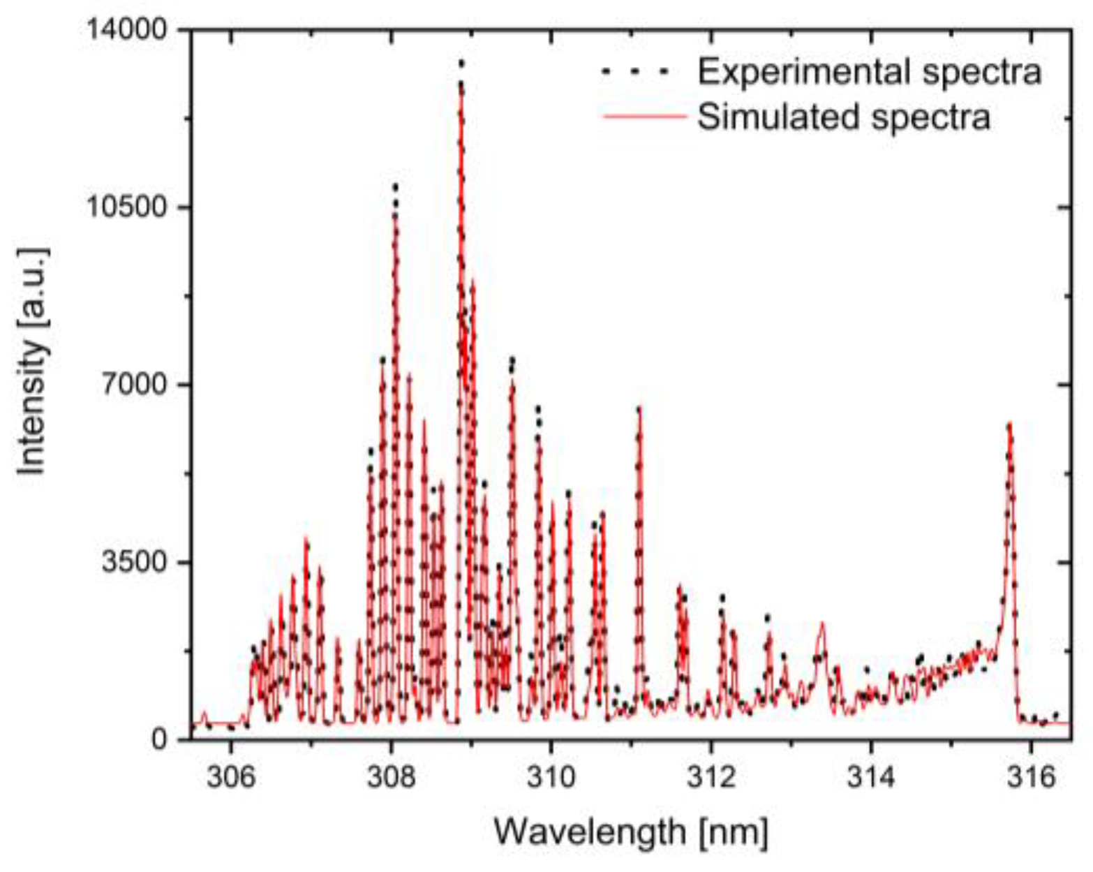
2.3. Gas Estimation Using OH(A-X) Simulations

As demonstrated in [43], the OH rotational temperature provides a reliable estimate of the gas temperature in plasma jets. In this work, the rotational temperature of the OH radical was evaluated by fitting the experimental spectrum of the OH (A-X) band with a synthetic spectrum generated based on the Boltzmann distribution of rotational levels, Honl-London factors, and a Gaussian function accounting for instrumental broadening [44]. This method takes into consideration the overlapping of N2(SPS) with OH bands with the emission and exclude its contribution. An example of such a simulated spectrum fitted to the experimental data is illustrated in Figure 3. The simulation was made for a spectra recorded from a plasma generated using the I-DBD configuration, operated without any molecular gas injection.

3. Results

3.1. Determination of the I- and Y-DBD Plasma Jets Operating Domains

First objective in this work was to gather information regarding the working domains of the plasma jets with injected molecular gases, in both geometries. This study was performed to facilitate a comparison of the operating conditions for each plasma jet geometry. The gases were introduced up to the highest reactive to main gas ratios compatible with the sources’ operation.
Figure 4 shows that each geometry is characterized by two main operational domains: a stable plasma region and a region where instabilities occur. Beyond these regions the plasma is either extinguished or cannot be operated under safe conditions, due to the risk of damaging the source by heating the tube in the proximity of the power electrode. A stable plasma jet refers to the regime in which the generated plasma jet remains anchored to a fixed point on the dielectric surface (glass/ quartz tube), maintaining its position over time. In contrast, instabilities are associated with the continuous shifting of the plasma jet’s anchoring point. Additionally, at high power, thermal energy is transferred from the plasma to the dielectric tube, potentially leading to source degradation. For both geometries, the lower boundary of the stability region corresponds to the minimum power required to ignite the discharge. In contrast, the upper boundary of the instability region indicates the maximum power that can be safely applied to the discharge while preserving the physical integrity of the plasma source. Also, for both geometries, within the power range of 40-60 W, the plasma jet does not extend outside the tube.
The analysis reveals that in the case of I-DBD geometry, where both the main gas and the molecular gases are injected prior to the discharge, the plasma remains stable at very low concentrations of O2/ N2 (ranging from 0 to 0.033%). In terms of power variation, for O2 injection, the plasma jet can be generated in a stable way with powers varied from 43 to 145 W, and 45 to 130 W for N2 addition.
Regarding the Y-DBD source, it can be easily observed that using this geometry the operating range can be considerably widened. Also, this geometry can operate with high molecular gas concentrations (up to 50 %) and ensures stable operation at low powers (40 W) and at high powers (~ 140 W) for both O2 and N2 injection. Additionally, for plasma generated using this geometry, when the concentration of the injected molecular gas exceeds 30%, the filamentary jet is no longer observed outside the tube. Instead, a diffuse emission still can be seen, known as the post-discharge or after-glow [45]. This zone is dominated by the presence of long lived species.

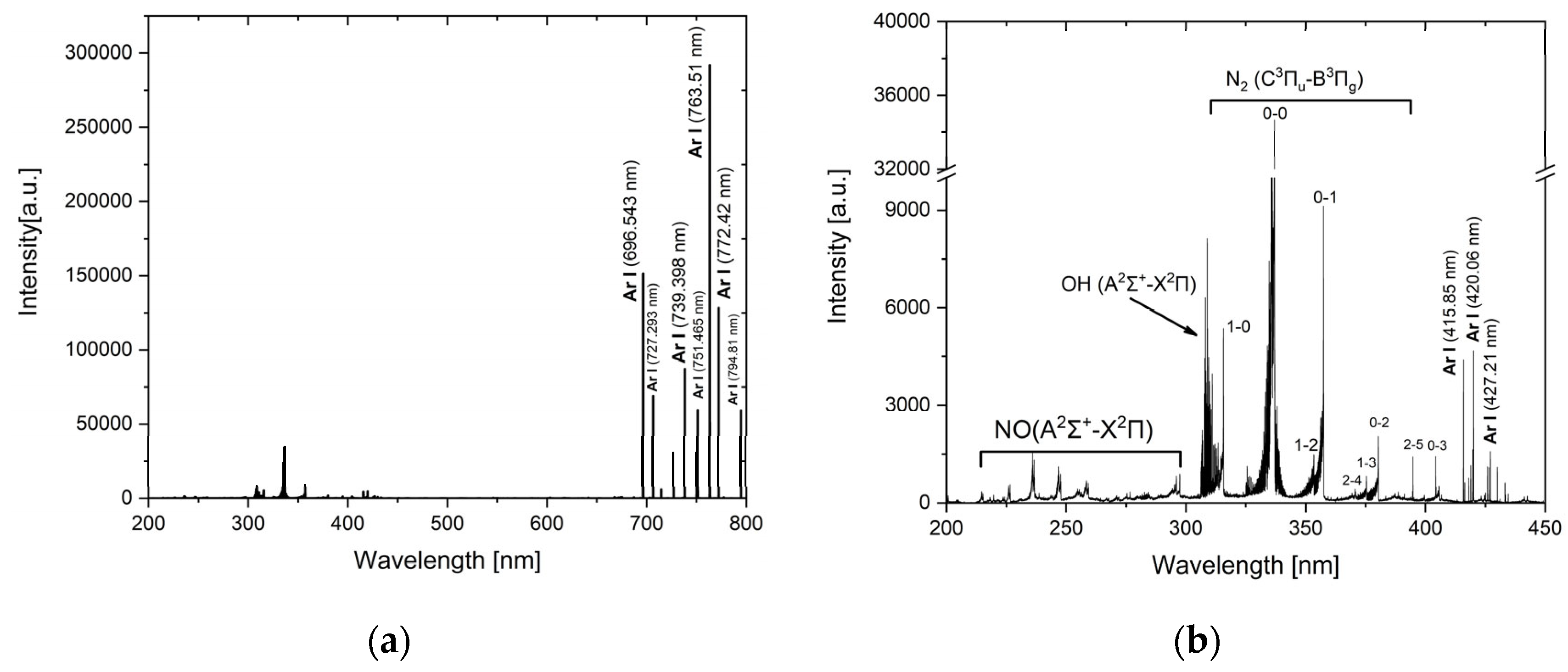
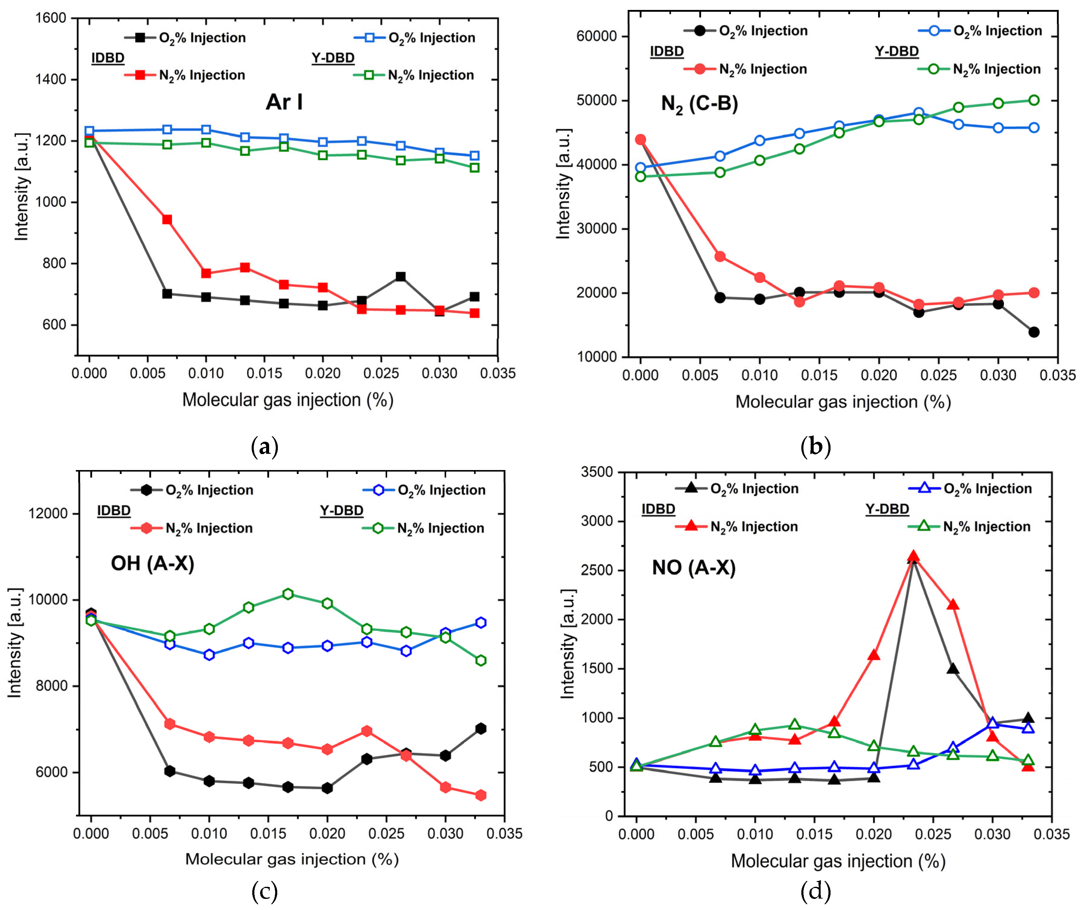
3.2. Behavior of the Emitting Species at the Tube Exit

In Figure 5 is presented a general spectrum of the plasma jet obtained at the exit of the tube, for an Y-DBD, operated at 100W RF power with 3000 sccm of Ar in absence of any reactive gas. The spectrum is similar to that obtained from the I-DBD in the same conditions. The predominant emission lines are those due to de-excitation of Ar atoms. The most intense are: Ar I (695.65 nm, 706.72 nm, 739.39 nm, 763.51 nm, 772.42 nm and, 794.81 nm). Additionally, in the low wavelength region of the spectrum, emissions from radical species such as γNO (A 2Σ+-X 2Π), OH (A 2Σ+, ν=0 – X 2Π, ν’’ = 0) and N2 (C 3Πu-B 3Πg) nm are observed, resulting from the uptake of N2, O2 gases and H2O water vapors from the atmospheric air.
A comparative spectral analysis was performed between the two discharge geometries, I-DBD and Y-DBD, focusing on the emission of the key species observed (as illustrated in Figure 6, respectively Ar (4p-4s) transitions, the band heads of the molecular nitrogen SPS system N2(C-B), the nitric oxide NO (A-X) band, and the hydroxyl radical OH (A-X) emission. Since high molecular gas injection lead to the extinction of the I-DBD plasma, only nitrogen and oxygen injection ratios up to 0.033% can be considered for a consistent comparison.
Concerning the Ar and N2 (SPS) emissions (Figure 6a and 6b), a very clear distinction between the two configurations is noticeable for both O2 and N2 injections. Thus, while in the case of I-DBD the emission of the investigated species drastically decreases with increasing molecular gas ratio, in contrast, for the Y-DBD configuration, the plasma emission remains high and even slightly increases in the case of N2(SPS). Similar trends are observed for the OH radical emission (Figure 6c): for the I-DBD configuration, increasing the molecular gas injection results in a decrease of the emission intensity by approximately a factor of two, while the OH signal remained nearly constant with only a slight increase observed for nitrogen injection around 0.015 %, for the Y-DBD source.
In respect to the NO radical (Figure 6d) generated by the I-DBD source, both molecular gas injections lead to a sharp increase in emission intensity (by a factor of approximately five), with a maximum around 0.02 % reactive gas injection, followed by a pronounced decrease. The plasma generated with the Y-DBD source exhibits a lower NO emission intensity and a smoother evolution with the injection ratio. In this case, the emission intensities evolved to a less pronounced maximum, occurring at lower flows for nitrogen, at about 0.015 %, and higher ones for oxygen, at 0.033%. In both cases, the intensity increases by about a factor of two compared to the situation without molecular gas injection. Overall, as a general observation, the NO emission behavior is different compared to the other investigated species.

4. Discussion

The main difference between the two plasma sources lies in the gas injection geometry. This has a significant impact on the plasma behavior, effectively extending the range of stable operation of the Y-DBD source from injection of small amounts of molecular gas (0.033%) up to concentrations as high as 50% (Figure 4). Also, the emission behavior is significantly modified (Figure 6). We show in the following, with the help of the schematic representation from Figure 7 which illustrate the nitrogen injection case, how the observed characteristics relate to the discharge phenomena and plasma processes in the two sources.
In Figure 7a is presented schematically the plasma jet in the I-DBD configuration, when operated solely in Ar. As showed before [29], the discharge consists of a filamentary plasma jet with a diameter of about 600 μm, surrounded by a diffuse plasma region. The dominant reactions in tube are electron impact excitation and ionization of Ar atoms inside and on the entire length the plasma filament, leading to the formation of Ar+ (ions) and of excited and metastable Arm (1s5, 1s3) states. The radial diffusion of peripheric electrons, and of long-life species (Ar+, Arm) feed with energy the discharge processes in the diffuse region which surrounds the filament. Despite the use of sole Ar as feeding gas, the emission recorded near the tube exit show however spectral signatures of the excited states of reactive species such as N2(C), OH(A), NO(A), N2+(B), which arise from the interaction of energetic electrons and Ar metastable species with residual impurities (H2O vapors) in the gas line, as well as from the diffusion of ambient N2, O2 gases and H2O vapors into the plasma jet.
When a molecular gas is injected premixed with Ar in the I-DBD (Figure 7b), the plasma is generated within the molecular mixture Ar-N2 (or Ar-O2). Because molecular gases efficiently absorb energy from electrons through multiple channels such as vibrational and rotational excitation modes, dissociation processes (leading to the formation of N or O atoms), and metastable species (like N2(A)) formation, the electron energy distribution in the discharge is modified compared to sole Ar injection case. As a result, less energy is available for ionization. This situation is well documented in literature [46,47]. A lower number of new charges which can compensate the charge losses are created, thus leading to discharge extinction with the increasing of molecular gas ratio in the admixture. Concluding, the premixed injection of the molecular gas induces new energy consuming processes that limits the operating range of the I-DBD at a given power, even at low injection ratios.
In comparison, in the Y-DBD configuration presented in Figure 7c), the molecular gas is introduced through the lateral inlet positioned downstream of the powered electrode. This geometry can be divided into two distinct regions, labeled A and B. From the extinction perspective, region A corresponds to a plasma formation zone like the plasma generation in the I-DBD configuration operating in sole Ar (Figure 7a). When the molecular gas is injected laterally, in region B, it interacts with the Ar plasma maintained by the upstream discharge. Consequently, the impact of molecular gas injection on the discharge extinction is diminished, and higher amounts of molecular gas can be introduced. From an energy transfer perspective, region A is characterized by intense production of Ar ions and metastable species via collisions with electrons, similar with the I-DBD operated solely in Ar, while region B involves, besides the processes sustained by electrons, an additional energy transfer from upstream Ar ions and metastable. It is also worth noting that the injected molecules predominantly enter the diffuse part of the jet. Here, the energy transfer mechanism is dominated by collisions between the electrons, argon metastable and ions diffusing from the filamentary region and the molecular species present in the surrounding plasma.
For a better understanding of the relationship between the spectral behavior and the processes in the plasma jet, the data presented in Figure 6 were normalized each to its highest value and are presented, together with the rotational temperatures and electron’s densities in Figure 8.
It is worth mentioning that the recorded emission contains the integrated signal from the diffuse and the bright filament discharge regions. However, the filament emission strongly exceeds the diffuse emission, and therefore the observed spectra behavior should be assigned to the excitation processes in the filament. The excitation in this region is dominated by electron-impact processes, as indicated by the strong Ar emission lines. Such excitation depends on the total number of electrons and on their energy distribution. Since the electron density remains nearly constant (~5 x 1014 cm-3) over the investigated injection ratio range (see Figure 8), it follows, consistently with the observed extinction behavior, that the spectral variations originate especially from modification in the electron energy distribution function.
Particularly, in the I-DBD injection type, the molecular gas (O2 or N2) already mixed with Ar enters the discharge and even when small molecular fractions (~ 0-0.033%) are present, the electron energy distribution function (EEDF) is shifted toward lower electron energies, as explained above during the discussing of the extinction phenomena. Therefore, beside the tendency to discharge extinction, a sharp decrease of the Ar lines intensity is observed. The similar behavior of the N2(C) and OH(A) bands intensities indicates that these emissions are also based on electronic excitation, and their decreased emissions indicate that the excitation processes become less efficient as the electron energy decreases.
However, the electronic excitation mechanisms differ for each of the species discussed above. A single step excitation process (R1) is sufficient for species already present in the gas phase, such as Ar and O2 (or N2). In contrast, the OH radical emission requires a two-step mechanism: first its formation (via electronic collisions (R2) or dissociative energy transfer (R3)), followed by excitation R4.
e f a s t + A r / N 2 / O 2 A r * / N 2 * / O 2 * + e s l o w
e f a s t + H 2 O O H + H + e s l o w
A r m + H 2 O O H + H + A r
e f a s t + O H O H * + e s l o w
(in the reactions R1-R4, e f a s t denotes the electrons entering the collision with energies higher than the excitation (R1 and R4) or dissociation (R2) thresholds, e s l o w denotes those electrons which lost their energy upon excitation or dissociation of the collided species.)
In the Y-DBD configuration, where the molecular gas is injected separately into the already existing Ar plasma, it is surprising that the Ar (5p-4s), N2(C-X) and OH(A-X) emissions remain nearly constant as the molecular gas concentration increases. This indicate that the EEDF in the filamentary zone is not affected, which can be explained only by a limited diffusion of the injected gas into the filament region. Therefore, in the Y-DBD case, the excitation processes might be driven by electron collisions (similarly to the I-DBD operated in Ar) only at the periphery of the Ar plasma filament, leading to electrons with decreased energy in this zone. Additionally, since the reactive gas no longer enters directly in the high electron energy plasma zone, it interacts mainly with lower energy electrons and long-lived metastable argon atoms Arm, transported from upstream or diffusing radially from the filamentary part of the jet. These metastable transfer excitation energy to the injected molecules through Penning excitation processes, such as the below mentioned R5. Under these conditions, the N2(C) emission exhibits a slight increase, reflecting this additional excitation channel provided through collisions with Ar metastable:
A r m + N 2 A r + N 2 C
The NO radical emission deserves a separate discussion, which must include, beside excitation, the NO formation mechanism. Unlike the O2 (or N2) and Ar which are injected as stable species in the plasma, or the OH which is formed by dissociation of water traces (R2 and R3) existing in the gas, the NO radical must be synthesized before being excited. The most likely NO formation mechanisms rely on the presence of atomic N and O, as well as N2 and O2 molecules originating either from the molecular gas injection or from ambient diffusion. These reactions are presented below:
O + N 2 N O + N
N + O 2 N O + O
N + O N O
As an additional argument in favor of the discussed mechanism based on R6 in the case of N2 injection, it is observed in Figure 8 that the increase in NO emission corroborate with a slight drop in the gas temperature (estimated as the OH rotational temperature). This cooling effect reflects the endothermic nature of the R6 [48], leading to NO formation.
The most efficient channel of atom formation is by electron collisions, which, additionally, is favored by the vibrational-rotational excitation of parent molecules, that diminishes the energy needed for electrons to dissociate the molecules (R9).
e f a s t + O 2   o r   N 2 O + O o r   N + N + e s l o w
Further on, the NO excitation (energy threshold 6.17 eV) is based on the electronic collisions (R10) or the energy transfer from metastable species like Arm and N2(A).
e f a s t + N O N O * + e s l o w
A r m ( o r   N 2 ( A ) ) + N O N O * + A r   ( o r   N 2 X )
In the I-DBD configuration with a small amount of premixed molecular gas, the number of produced atoms initially increases with the injected molecular fraction due to the increasing of the number of molecular partners involved in reaction (R9). However, this also causes a depletion of the high-energy tail of the EEDF, and once the injected gas ratio exceeds a certain threshold, the atom production begins to decrease because the number of electrons having energy exceeding the dissociation threshold becomes insufficient. According to this behavior of the dissociation process, there is an optimal value of the injected gas ratio leading to a maximum production of O (or N) atoms. Since NO molecules are easily excited (R10 and R11), their emission reaches a maximum at that injected gas ratio that optimizes the production of atomic precursors. This behavior is clearly illustrated in Figure 8a and Figure 8b for both O2 and N2 injections in the I-DBD, where the emission intensity exhibits well-defined maxima at specific injected gas ratios.
In the Y-DBD case, the process of injection affects the peripheric zone of the filament, while the filament core properties remain like in an I-DBD fed with Ar only. In this peripheral zone, dissociation acts on the molecules that diffuse from the injection point toward the filament edge, and N (or O) atoms are produced along the filament through collisions with high-energy electrons diffusing from the core to the periphery (like described by R9). In this region, the depletion of the high energy tail of the EEDF is continuously compensated by the influx of energetic electrons from the core region. Accordingly, the production of N (or O) atoms inside the tube increases as the injected molecular gas ratio rises. At the tube exit, these atoms interact with the gases diffusing into the plasma from the surrounding air, which enhances the formation of NO, depending on the local availability of O or N atoms. At higher injection ratios, however, collisional quenching of NO* states, together with the formation of secondary species such as NO2, N2O, and O3, becomes dominant and leads to a decrease in the NO emission [49]. The observed increase followed by a decrease in NO emission intensity for Y-DBD configuration agrees with this interpretation Figure 8c and Figure 8d.
It is worth noting that, in the case of N2 injection, the NO emission maximum appears at lower injected gas ratios compared to O2 injection. Considering the dissociation thresholds, the opposite trend would be expected, since the dissociation energy of N2 (9.76 eV) is significantly higher than that of O2 (5.12 eV). This suggest that an additional dissociation pathway must be active or that NO is generated directly through alternative channels.
A plausible explanation is that N2(A) metastable molecules are present at high concentrations in this region, given their long radiative lifetime (~ 2s) and their efficient production through electron impact (R12) and energy transfer from Arm (R13).
e f a s t + N 2 ( X ) N 2 A + e s l o w
A r * + N 2 ( X ) A r + N 2 A
Therefore, when N2 is injected, two additional routes will enhance NO production: a channel enabling easier N2 dissociation (R14 and R15), (the electron dissociation mechanism is more effective to the metastable state N2(A), because its dissociation threshold is only 3.53 eV), and a channel that leads directly to NO (R16).
A r m + N 2 ( A ) A r + N + N
e f a s t + N 2 ( A ) e s l o w + N + N
N 2 ( A ) + O N O + N ( D )
The main difference between the two configuration is that, in the mixed gas configuration, NO evolution is controlled by kinetics, governed by electron-impact processes inside the discharge filament, while in the Y-DBD it becomes controlled by formation, diffusion and spatial overlap of reactive species outside the filament. Concluding, in respect to NO production, the present results show that I-DBD source with upstream injection of a mixed gas is superior compared to Y-DBD, the dissociation being more active in the filament core, where higher amounts of N or O species produced at same injection ratios, despite the decreased electron energy. The complementary reactants (i.e. O2 or N2) are supplied by the diffusion of ambient air into the plasma. This leads to more NO molecules and a higher NO emission in the I-DBD configuration.
As a final remark, the present work demonstrates the usefulness of spectral discharge diagnostics in elucidating the mechanisms of species formation in cold atmospheric-pressure plasma jets. The results provide valuable guidance for selecting conditions that optimize the production of reactive species—such as NO radicals—at the tube exit. These findings should be regarded as a starting point for further studies aimed at determining the nature and concentration of reactive species at various distances from the tube exit, which is particularly relevant for surface processing applications (e.g., wettability control, activation, cleaning, decontamination, and sterilization). They are also important for quantifying the total amount of reactive species released into the surroundings of the plasma jet. In the latter case, the large contact interface between the jet and the reactive molecular gas, combined with the more energetic and spatially extended filament of the Y-DBD configuration, may make this configuration especially suitable for volume applications such as air purification and liquid treatment.

5. Conclusions

The knowledge of the properties of atmospheric pressure plasma sources and their ability to produce reactive species is of paramount importance for applications.
The results show that the gas injection configuration has an important influence on plasma stability and reactive species production. In the premixed gas configuration (I-DBD) where the processes are driven by electronic collisions, the injection of molecular gases causes strong modification of the electron energy distribution, leading to plasma extinction and reduced emission of reactive species. In contrast, the downstream introduction of the molecular gas in the discharge (Y-DBD), leads to a more controlled plasma, thereby extending the stable operating range up to high molecular gas concentrations. Also, the separation between the argon discharge region and the molecular injection zone allows the plasma chemistry to evolve more gradually, favoring processes involving heavy species, rather than being dominated by electron impact. As a result, the plasma remains stable over a significantly broader range of molecular gas concentration, from small amounts up to 50%, and consequently a different behavior of the emission of species is exhibited at the tube exit.
From the practical point of view, the results show that plasmas generated using the Y-DBD configuration are more stable and capable of sustaining a balanced production of reactive species such as NO(A), OH(A), and N2(C), while the I-DBD configuration can be tuned to selectively enhance NO generation.
The single-filament RF plasma jet, characterized by its long spatial extension beyond the source exit and its large interaction surface with the surrounding medium along its length, is particularly well suited—compared to other atmospheric-pressure plasma jets—for applications that require the treatment of large volumes of matter. Examples include air decontamination, decomposition of volatile organic compounds, gas-phase chemical processing, pollutant degradation, and nanomaterial synthesis in liquids. Furthermore, the present work demonstrates the usefulness of electrical and spectroscopic discharge diagnostics in elucidating the mechanisms of species formation in cold atmospheric-pressure plasma jets.

Author Contributions

Conceptualization, C.C. and G.D.; methodology, C.C., B.M., M.B., G.D.; validation, C.C., M.B., B.M.; investigation, C.C., M.B., C.S.; writing—original draft preparation, C.C., GD; writing—review and editing, B.M., G.D.; visualization, C.C.; supervision, G.D.; funding acquisition: G.D. All authors have read and agreed to the published version of the manuscript.

Funding

This work was supported by the Romanian Ministry of Research, Innovation, and Digitization under PNCDI IV (Program 5/5.9/ELI-RO, project ELI-RO/RDI/2024_015; Program LAPLAS VII, Contract No. 30N/2023) and by the European Union through the EUROfusion Consortium (workpackage WPTRED).

Acknowledgments

Part of this work has been carried out within the framework of the EUROfusion Consortium, funded by the European Union via the Euratom Research and Training Programme (Grant Agreement No 101052200 — EUROfusion). Views and opinions expressed are however those of the author(s) only and do not necessarily reflect those of the European Union or the European Commission. Neither the European Union nor the European Commission can be held responsible for them.

References

  1. Liu, Y.; Liu, Z. Correlation of Reflected Plasma Angle and Weld Pool Thermal State in Plasma Arc Welding Process. J Manuf Process 2022, 75, 1111–1122. [Google Scholar] [CrossRef]
  2. Blackburn, M.J.; Malley, D.R. Plasma Arc Melting of Titanium Alloys. Mater Des 1993, 14, 19–27. [Google Scholar] [CrossRef]
  3. Kim, S.-I.; Kim, M.-H. Evaluation of Cutting Characterization in Plasma Cutting of Thick Steel Ship Plates. International Journal of Precision Engineering and Manufacturing 2013, 14, 1571–1575. [Google Scholar] [CrossRef]
  4. Tendero, C.; Tixier, C.; Tristant, P.; Desmaison, J.; Leprince, P. Atmospheric Pressure Plasmas: A Review. Spectrochim Acta Part B At Spectrosc 2006, 61, 2–30. [Google Scholar] [CrossRef]
  5. Adamovich, I.; Agarwal, S.; Ahedo, E.; Alves, L.L.; Baalrud, S.; Babaeva, N.; Bogaerts, A.; Bourdon, A.; Bruggeman, P.J.; Canal, C. The 2022 Plasma Roadmap: Low Temperature Plasma Science and Technology. J Phys D Appl Phys 2022, 2022, 373001. [Google Scholar] [CrossRef]
  6. Laroussi, M.; Tendero, C.; Lu, X.; Alla, S.; Hynes, W.L. Inactivation of Bacteria by the Plasma Pencil. Plasma Processes and Polymers 2006, 3, 470–473. [Google Scholar] [CrossRef]
  7. Toda, K.; Ichiki, R.; Kanbara, Y.; Kojima, K.; Tachibana, K.; Furuki, T.; Kanazawa, S. Bright Nitriding Using Atmospheric-Pressure Pulsed-Arc Plasma Jet Based on NH Emission Characteristics. Jpn J Appl Phys 2020, 59. [Google Scholar] [CrossRef]
  8. Zhao, S.; de Wege, R. van; Sobota, A. Nitric Oxide (NO) Production in a KHz Pulsed Ar Plasma Jet Operated in Ambient Air. Plasma Sources Sci Technol 2025, 34. [Google Scholar] [CrossRef]
  9. Allen, D.; Hayhurst, A.N. The Chemical Reactions of Nitric Oxide with Solid Carbon and Catalytically with Gaseous Carbon Monoxide. Fuel 2015, 142, 260–267. [Google Scholar] [CrossRef]
  10. Stanmore, B.R.; Tschamber, V.; Brilhac, J.F. Oxidation of Carbon by NOx, with Particular Reference to NO2 and N2O. Fuel 2008, 87, 131–146. [Google Scholar] [CrossRef]
  11. Park, C.S.; Kim, D.Y.; Kim, S.O. Reactive Oxygen Species Controllable Nonthermal Atmospheric Pressure Plasmas Using Coaxial Geometry for Biomedical Applications. IEEE Transactions on Plasma Science 2014, 42, 2490–2491. [Google Scholar] [CrossRef]
  12. Dedrick, J.; Schröter, S.; Niemi, K.; Wijaikhum, A.; Wagenaars, E.; De Oliveira, N.; Nahon, L.; Booth, J.P.; O’Connell, D.; Gans, T. Controlled Production of Atomic Oxygen and Nitrogen in a Pulsed Radio-Frequency Atmospheric-Pressure Plasma. J Phys D Appl Phys 2017, 50. [Google Scholar] [CrossRef]
  13. T. Nagatomo, T.A.F.M.K.E. and K.N. Takuya Nagatomo_Jpn. J. Appl. Phys. 55, 01AB06 (2016). Jpn. J. Appl. Phys 2016, 55. [CrossRef]
  14. Klyucharev, A.N.; Pechatnikov, P.A. Plasma Ion Source Based on the Barrier Discharge for Earth Atmosphere Pollution Monitoring Systems. Russian Journal of Physical Chemistry B 2014, 8, 783–786. [Google Scholar] [CrossRef]
  15. Shirafuji, T.; Oh, J.-S. Reaction Kinetics of Active Species from an Atmospheric Pressure Plasma Jet Irradiated on the Flowing Water Surface-Effect of Gas-Drag by the Sliding Water Surface.
  16. Belmonte, T.; Noël, C.; Gries, T.; Martin, J.; Henrion, G. Theoretical Background of Optical Emission Spectroscopy for Analysis of Atmospheric Pressure Plasmas. Plasma Sources Sci Technol 2015, 24, 064003. [Google Scholar] [CrossRef]
  17. Pleslić, S.; Katalenić, F. Monitoring and Diagnostics of Non-Thermal Plasmas in the Food Sector Using Optical Emission Spectroscopy. Applied Sciences 2025, 15, 8325. [Google Scholar] [CrossRef]
  18. Zaplotnik, R.; Primc, G.; Vesel, A. Optical Emission Spectroscopy as a Diagnostic Tool for Characterization of Atmospheric Plasma Jets. Applied Sciences 2021, 11, 2275. [Google Scholar] [CrossRef]
  19. Hubka, Z.; Novák, J.; Majerová, I.; Green, J.T.; Velpula, P.K.; Boge, R.; Antipenkov, R.; Šobr, V.; Kramer, D.; Majer, K.; et al. Mitigation of Laser-Induced Contamination in Vacuum in High-Repetition-Rate High-Peak-Power Laser Systems. Appl Opt 2021, 60, 533. [Google Scholar] [CrossRef]
  20. Tolenis, T.; Vazquez, S.; Ramalis, L.; Havlík, M.; Chauvin, A.; Těreščenko, A.; Espinoza, S.; Fučíkova, A.; Andreasson, J.; Havlickova, I.; et al. Complex Analysis of Laser Induced Contamination in High Reflectivity Mirrors. High Power Laser Science and Engineering 2025, 1–16. [Google Scholar] [CrossRef]
  21. Stancu, C.; Alegre, D.; Ionita, E.R.; Mitu, B.; Grisolia, C.; Tabares, F.L.; Dinescu, G. Cleaning of Carbon Materials from Flat Surfaces and Castellation Gaps by an Atmospheric Pressure Plasma Jet. Fusion Engineering and Design 2016, 103, 38–44. [Google Scholar] [CrossRef]
  22. Dinescu, G.; Ionita, E.R.; Luciu, I.; Grisolia, C. Flexible Small Size Radiofrequency Plasma Torch for Tokamak Wall Cleaning. Fusion Engineering and Design 2007, 82, 2311–2317. [Google Scholar] [CrossRef]
  23. Yehia, S.A.; Zarif, M.E.; Bita, B.I.; Teodorescu, M.; Carpen, L.G.; Vizireanu, S.; Petrea, N.; Dinescu, G. Development and Optimization of Single Filament Plasma Jets for Wastewater Decontamination. Plasma Chemistry and Plasma Processing 2020, 40, 1485–1505. [Google Scholar] [CrossRef]
  24. Yehia, S.A.; Petrea, N.; Grigoriu, N.; Vizireanu, S.; Zarif, M.E.; Carpen, L.G.; Ginghina, R.E.; Dinescu, G. Organophosphorus Toxic Compounds Degradation in Aqueous Solutions Using Single Filament Dielectric Barrier Discharge Plasma Jet Source. Journal of Water Process Engineering 2022, 46. [Google Scholar] [CrossRef]
  25. Ionita, M.D.; Vizireanu, S.; Stoica, S.D.; Ionita, M.; Pandele, A.M.; Cucu, A.; Stamatin, I.; Nistor, L.C.; Dinescu, G. Functionalization of Carbon Nanowalls by Plasma Jet in Liquid Treatment. European Physical Journal D 2016, 70. [Google Scholar] [CrossRef]
  26. Vizireanu, S.; Panaitescu, D.M.; Nicolae, C.A.; Frone, A.N.; Chiulan, I.; Ionita, M.D.; Satulu, V.; Carpen, L.G.; Petrescu, S.; Birjega, R.; et al. Cellulose Defibrillation and Functionalization by Plasma in Liquid Treatment. Sci Rep 2018, 8, 15473. [Google Scholar] [CrossRef]
  27. Bolouki, N.; Hsieh, J.H.; Li, C.; Yang, Y.Z. Emission Spectroscopic Characterization of a Helium Atmospheric Pressure Plasma Jet with Various Mixtures of Argon Gas in the Presence and the Absence of De-Ionized Water as a Target. Plasma 2019, 2, 283–293. [Google Scholar] [CrossRef]
  28. Zhu, W.C.; Li, Q.; Zhu, X.M.; Pu, Y.K. Characteristics of Atmospheric Pressure Plasma Jets Emerging into Ambient Air and Helium. J Phys D Appl Phys 2009, 42. [Google Scholar] [CrossRef]
  29. Teodorescu, M.; Bazavan, M.; Ionita, E.R.; Dinescu, G. Characteristics of a Long and Stable Filamentary Argon Plasma Jet Generated in Ambient Atmosphere. Plasma Sources Sci Technol 2015, 24. [Google Scholar] [CrossRef]
  30. Anton Yu Nikiforov, E.-R.I.G.D. and C.L. Nikifirov_Plasma Phys. Control. Fusion 58 (2016) 014013 (12pp). Plasma Phys. Control. Fusion 2016, 58.
  31. Index. In Principles of Plasma Discharges and Materials Processing; Wiley, 2005; pp. 749–757.
  32. Lin, P.; Zhang, J.; Nguyen, T.; Donnelly, V.M.; Economou, D.J. Numerical Simulation of an Atmospheric Pressure Plasma Jet with Coaxial Shielding Gas. J Phys D Appl Phys 2021, 54, 075205. [Google Scholar] [CrossRef]
  33. Reuter, S.; Tresp, H.; Wende, K.; Hammer, M.U.; Winter, J.; Masur, K.; Schmidt-Bleker, A.; Weltmann, K.D. From RONS to ROS: Tailoring Plasma Jet Treatment of Skin Cells. IEEE Transactions on Plasma Science 2012, 40, 2986–2993. [Google Scholar] [CrossRef]
  34. Reuter, S.; Winter, J.; Schmidt-Bleker, A.; Tresp, H.; Hammer, M.U.; Weltmann, K.D. Controlling the Ambient Air Affected Reactive Species Composition in the Effluent of an Argon Plasma Jet. IEEE Transactions on Plasma Science 2012, 40, 2788–2794. [Google Scholar] [CrossRef]
  35. Lin, P.; Zhang, J.; Nguyen, T.; Donnelly, V.M.; Economou, D.J. Numerical Simulation of an Atmospheric Pressure Plasma Jet with Coaxial Shielding Gas. J Phys D Appl Phys 2021, 54, 075205. [Google Scholar] [CrossRef]
  36. Schüttler, S.; Kaufmann, J.; Golda, J. Nitrogen Fixation and H2O2 Production by an Atmospheric Pressure Plasma Jet Operated in He–H20–N2–O2 Gas Mixtures. Plasma Processes and Polymers 2024, 21. [Google Scholar] [CrossRef]
  37. Mohamed, A.A.H.; Basher, A.H.; Almarashi, J.Q.M.; Ouf, S.A. Susceptibility of Staphylococcus Epidermidis to Argon Cold Plasma Jet by Oxygen Admixture. Applied Sciences (Switzerland) 2021, 11. [Google Scholar] [CrossRef]
  38. Asghar, A.H.; Galaly, A.R. The Effect of Oxygen Admixture with Argon Discharges on the Impact Parameters of Atmospheric Pressure Plasma Jet Characteristics. Applied Sciences (Switzerland) 2021, 11. [Google Scholar] [CrossRef]
  39. Lu, X.; Naidis, G.V.; Laroussi, M.; Reuter, S.; Graves, D.B.; Ostrikov, K. Reactive Species in Non-Equilibrium Atmospheric-Pressure Plasmas: Generation, Transport, and Biological Effects. Phys Rep 2016, 630, 1–84. [Google Scholar] [CrossRef]
  40. Griem, H.R.; Kolb, A.C.; Shen, K.Y. Stark Broadening of Hydrogen Lines in a Plasma. Physical Review 1959, 116, 4–16. [Google Scholar] [CrossRef]
  41. Gigosos, M.A.; Gonzalez, M.A.; Cardenoso, V. Spectrochimica Acta Electronica Computer Simulated Balmer-Alpha,-Beta and-Gamma Stark Line Profiles for Non-Equilibrium Plasmas Diagnostics. Spectrochimica Acta Part B 2003, 58, 1489–1504. [Google Scholar] [CrossRef]
  42. Chan, S.-K.; Montaser, A. Determination of Electron Number Density via Stark Broadening with an Improved Algorithm; 1989; Vol. 448;
  43. Bazavan, M.; Teodorescu, M.; Dinescu, G. Confirmation of OH as Good Thermometric Species for Gas Temperature Determination in an Atmospheric Pressure Argon Plasma Jet. Plasma Sources Sci Technol 2017, 26. [Google Scholar] [CrossRef]
  44. Abdel-Fattah, E.; Bazavan, M.; Shindo, H. Temperature Measurements in Microwave Argon Plasma Source by Using Overlapped Molecular Emission Spectra. Phys Plasmas 2015, 22. [Google Scholar] [CrossRef]
  45. Chen, C.J.; Li, S.Z. Investigation of a Nitrogen Post-Discharge of an Atmospheric-Pressure Microwave Plasma Torch by Optical Emission Spectroscopy. Phys Plasmas 2017, 24. [Google Scholar] [CrossRef]
  46. Gupta, S.; Gangwar, R.K.; Srivastava, R. Diagnostics of Ar/N2 Mixture Plasma with Detailed Electron-Impact Argon Fine-Structure Excitation Cross Sections. Spectrochim Acta Part B At Spectrosc 2018, 149, 203–213. [Google Scholar] [CrossRef]
  47. Boris, D.R.; Petrov, G.M.; Lock, E.H.; Petrova, T.B.; Fernsler, R.F.; Walton, S.G. Controlling the Electron Energy Distribution Function of Electron Beam Generated Plasmas with Molecular Gas Concentration: I. Experimental Results. Plasma Sources Sci Technol 2013, 22, 065004. [Google Scholar] [CrossRef]
  48. Rouwenhorst, K.H.R.; Jardali, F.; Bogaerts, A.; Lefferts, L. From the Birkeland–Eyde Process towards Energy-Efficient Plasma-Based NO X Synthesis: A Techno-Economic Analysis. Energy Environ Sci 2021, 14, 2520–2534. [Google Scholar] [CrossRef]
  49. Gaens, W. Van; Iseni, S.; Schmidt-Bleker, A.; Weltmann, K.D.; Reuter, S.; Bogaerts, A. Numerical Analysis of the Effect of Nitrogen and Oxygen Admixtures on the Chemistry of an Argon Plasma Jet Operating at Atmospheric Pressure. New J Phys 2015, 17. [Google Scholar] [CrossRef]
Figure 1. Illustration of the I and Y plasma jet configurations emphasizing the reactive gas injection peculiarities.
Preprints 185146 g001
Figure 2. (a) The experimental setup. It consists of the plasma generation and control system and the spectral investigation system. The figured plasma source is of Y-DBD type; (b) Detailed view of the geometry used for spectral data collection.
Preprints 185146 g002
Figure 3. OH (A-X) spectrum overlaped on experimental spectrum acquired for Ar flow 3000 sccm, using a power of 100 W. Rotational temperature computed in this case: Trot=630 ± 15 K.
Preprints 185146 g003
Figure 4. Comparative view of the working domains of the I and Y-DBD in a) Ar/O2 admixtures, b) Ar/N2 admixtures.
Preprints 185146 g004
Figure 5. General OES spectra for the plasma jet (near the tube edge); (a) extended view of 200-800 nm spectral range, (b) detailed view of the of the 200-450 nm spectral range.
Preprints 185146 g005
Figure 6. Spectral comparison between I and Y- DBD sources: (a) Ar I, (b) N2(C-B), (c) OH (A-X), and (d) NO (A-X) emissions (full symbols are used for I-DBD, while empty ones are used for the Y-DBD configuration).
Preprints 185146 g006
Figure 7. Most important species and processes occurring in I-DBD source with (a) Ar injection, (b) Ar + N2 injection, and (c) Y-DBD source with Ar + N2 injection.
Preprints 185146 g007
Figure 8. Normalized emission intensities of the investigated species (each scaled to its maximum value), shown together with the rotational temperature obtained from OH(A-X) simulations, and the electron densities determined from Stark lines broadening.
Preprints 185146 g008
Disclaimer/Publisher’s Note: The statements, opinions and data contained in all publications are solely those of the individual author(s) and contributor(s) and not of MDPI and/or the editor(s). MDPI and/or the editor(s) disclaim responsibility for any injury to people or property resulting from any ideas, methods, instructions or products referred to in the content.
Copyright: This open access article is published under a Creative Commons CC BY 4.0 license, which permit the free download, distribution, and reuse, provided that the author and preprint are cited in any reuse.
Prerpints.org logo

Preprints.org is a free preprint server supported by MDPI in Basel, Switzerland.

Subscribe

Disclaimer

Terms of Use

Privacy Policy

Privacy Settings

© 2025 MDPI (Basel, Switzerland) unless otherwise stated