
Submitted:
11 November 2025
Posted:
12 November 2025
You are already at the latest version
Abstract
Composite materials are preferred in many industrial fields due to their superior prop-erties such as high mechanical strength, light weight, corrosion resistance, and long service life. These materials play a critical role especially in the marine and renewable energy sectors. However, despite these advantages, composites are not completely im-mune to environmental conditions. Factors such as moisture, saltwater, UV radiation, and temperature variations can negatively affect the structural integrity of these mate-rials over time. In marine environments, composite materials are continuously exposed to high humid-ity, salt concentration, and ultraviolet radiation. These environmental factors lead to the diffusion of water molecules into the material, causing weakening at the fiber–matrix interface. As a result, the mechanical strength of the composite decreases, lead-ing to a reduction in its structural performance. This is a significant issue for long-term marine applications. Nevertheless, due to their advantages, composites are widely used in ship superstructures (decks, bulkheads, masts, rudders, pipes, valves) and in com-mercial vessels (lifeboats, ferries, fishing boats). They are also commonly used in recre-ational marine vehicles such as speedboats, racing yachts, and canoes. On the other hand, the depletion of fossil fuel resources and the increasing importance of environmental sustainability have accelerated interest in renewable energy sources. In this context, wind energy has become a prominent renewable source due to its environmentally friendly, cost-effective, and sustainable nature. Wind turbines con-sist of components such as the tower, rotor, shaft, generator, and especially blades. The design and material selection of the blades are of great importance for turbine efficien-cy. Therefore, composite materials are increasingly used in blade manufacturing. Alt-hough metals were initially employed, today glass fiber-reinforced polymers (GFRP) have become dominant in wind turbine blades. This preference is due to advantages such as the low cost, easy availability, light weight, and high strength of glass fibers. Furthermore, their impact and fatigue resistance, corrosion resistance, and ease of molding during production make GFRP ideal for large-scale turbine blades. Currently, approximately 95% of the composite material used in a turbine blade consists of glass fiber, while the remaining 5% is carbon fiber. In light of this information, both the marine and wind energy sectors greatly benefit from the technical and economic advantages provided by composite materials. In this study, the damage processes occurring in adhesive-bonded regions of fiber-reinforced polymer (FRP) composites under environmental conditions were experimentally inves-tigated. Bending tests were performed on GFRP and CFRP composite specimens com-monly used in marine vehicles and offshore wind turbine blades. For marine applica-tions, three-point bending (3PB) tests were conducted on GFRP and CFRP specimens conditioned in seawater. In contrast, four-point bending (4PB) tests were performed on specimens used in offshore wind turbine blade applications. The results provided a comprehensive evaluation of the onset of damage in adhesive joints, the effect of sea-water on mechanical properties, damage behavior, and load-carrying capacity. Within the scope of this study, adhesive-bonded joints of glass fiber-reinforced polymer (GFRP) and carbon fiber-reinforced polymer (CFRP) composite materials commonly used in marine and offshore wind turbine applications were experimentally investi-gated under environmental effects. The specimens were prepared with unidirectional twill weave at a 90° orientation; GFRP composites consisted of 7 layers, while CFRP composites consisted of 8 layers. The samples were cut into 24 pieces according to ASTM D5868-01 standard, and an epoxy–hardener mixture was manually applied to the prepreg surfaces, followed by a one-day curing period. After gelation of the resin, the final composite materials were produced using the hot-pressing method.
The single-lap adhesive joints were immersed in seawater obtained from the Aegean Sea (22 °C temperature, 3.3–3.7% salinity) for 1, 2, and 3 months in separate containers to simulate marine environmental conditions. Three-point bending tests were per-formed on the specimens exposed to marine conditions in accordance with ASTM D790 standard, while four-point bending tests were conducted on specimens representing offshore wind turbine applications. The damages that occurred during testing were examined in detail using a ZEISS GEMINI SEM 560 scanning electron microscope (SEM). As a result of the three-point bending tests conducted under marine environmental conditions, the Young’s modulus of GFRP specimens decreased by 5.94%, 8.90%, and 12.98% after 1, 2, and 3 months, respectively, compared to the specimens tested under dry conditions.
Keywords:
adhesive bonding
; composite materials
; diffusion
; four point bending test
; three point bending test
1. Introduction
In modern engineering applications, composite materials, which are increasingly preferred, are synthetic, multi-phase systems produced by combining two or more different phases within a defined structure. In this context, both synthetic and natural fiber-reinforced composites are utilized [1,2]. Composites can simultaneously fulfill multiple functions in modern applications by combining the lightness and flexibility of the matrix with the superior properties of the reinforcing fillers [3].
To meet specific requirements, the adjustment of electrical properties involves the selection of compression pressure, particle size, and composition. In these materials, there exists a clearly defined interface between phases, which provides enhanced performance characteristics that cannot be achieved by individual components alone. Due to their advantages such as lightness, high strength, flexibility, and environmental resistance, composites have gained strategic importance [4,5].
The effective and safe use of these materials is not limited to understanding the properties of their components but also requires an understanding of how these properties contribute to the overall material integrity. The behavior of composites becomes complex when subjected to variable external conditions such as impact, temperature fluctuations, vibration, and cyclic loading. Therefore, fiber-reinforced composites are widely preferred in aerospace and other engineering fields due to their excellent specific strength, stiffness, and corrosion resistance. At this point, the interfacial region that ensures load transfer within the material is of vital importance. The structural integrity of the interface enables efficient load transfer, while weaknesses in this region can negatively affect the overall durability of the structure [6,7].
Composites formed by combining phases with different physical and chemical properties in an orderly manner offer both structural and functional advantages in various engineering fields. These materials, which stand out for their high strength to weight ratio, formability, and resistance to environmental conditions, are widely used in aircraft and automotive industries, construction, energy systems, and defense technologies. In tribological applications, environmental conditions should also be considered when selecting GFRP and CFRP [8,9,10].
In practical applications, fiber-reinforced polymer (FRP) composites are commonly used in marine environments and wind turbine blades due to their lightweight structure and high structural strength. However, since most turbine blades consist of adhesively bonded composite parts, these regions may suffer damage over time due to environmental effects and fatigue. Therefore, understanding the deterioration of bonding surfaces and interfacial regions is critical for ensuring the long-term durability of the blades [11,12,13]. The sustainability of structural integrity depends not only on the mechanical properties of the reinforcing fibers and matrix but also on the quality of their interaction, the homogeneity of the interface, and the accuracy of manufacturing techniques. Under dynamic loading, temperature variations, and wind effects, the behavior of the interface plays a decisive role. Particularly, fiber orientation directly affects load distribution, shaping the overall performance of the structure [14].
Similarly, FRP structures used in marine environments are exposed to harsh conditions such as wave forces, the chemical effects of seawater, and thermal cycles; therefore, the strength of adhesive and interfacial regions constitutes a critical design issue in marine engineering as well [15,16]. Hence, comparing carbon fiber-reinforced composites with glass fiber-reinforced composites will enable a better understanding of their superior properties [17].
Today, fiber-reinforced polymer (FRP) composites are among the fundamental materials preferred in both wind turbine blades and marine structural components. In wind turbines, the lightweight and high-strength nature of large-span blades not only enhances energy efficiency but also challenges structural durability. Since these structures are mostly composed of multiple composite parts joined by adhesive bonding, interfacial and bonding regions are at risk of degradation over time under environmental effects and cyclic loading. Similarly, FRP structures used in marine environments face critical design challenges related to interface strength due to exposure to wave forces, saltwater, ultraviolet radiation, temperature changes, and repeated mechanical loads [18,19,20].
In both application areas, the microstructural interactions in the interfacial region, load transfer mechanisms, and manufacturing quality are critical to maintaining structural integrity. Therefore, to ensure the long-term and reliable performance of composite structures in wind turbines and marine environments, comprehensive analyses and improvement strategies should be developed regarding the durability of adhesives and interfacial materials [12]. A deep understanding of the damage formation mechanisms in interface regions under environmental stresses and cyclic mechanical loads is of vital importance for the sustainability and safety of these technologies.
- Applications of GFRP and CFRP Composite Materials in Offshore Wind Turbine Blades and Marine Vehicles
In wind energy technologies, blade design represents a critical engineering challenge in terms of both structural strength and energy efficiency. The materials used in offshore wind turbine blades are selected to withstand harsh environmental conditions such as high humidity, salinity, temperature fluctuations, and repeated mechanical loads. In this context, glass fiber-reinforced polymer (GFRP) and carbon fiber-reinforced polymer (CFRP) composites are widely preferred due to their specific strength, corrosion resistance, and ease of manufacturing [21,22].
GFRP materials are generally used in the outer shell (skin) and surface layers of the blades due to their low density, high impact resistance, and cost-effective production advantages. In these regions, GFRP distributes the stresses generated by aerodynamic loads uniformly, maintaining the overall structural stability of the blade. In contrast, since the root and spar (main beam) sections of the blade require higher stiffness and bending strength, CFRP reinforcements are commonly employed. CFRP materials, with their high elastic modulus and fatigue resistance, contribute to reducing the overall weight of long blades and improving their vibration performance [23,24].
Figure 1 illustrates the types of materials preferred in different structural regions of a wind turbine blade.
Hybrid lamination strategies are increasingly being used in modern wing designs. In this approach, GFRP and CFRP layers are used together to achieve a balance between cost-effectiveness and mechanical performance. CFRP is used in high-load-bearing layers, particularly in spar skins or spar-cover transition areas, while GFRP is preferred for external surfaces. This helps control material costs and extends the fatigue life of the structure [26]. In marine vessels, the use of composite materials has become widespread for reasons such as reducing structural weight, increasing corrosion resistance, and reducing maintenance costs. GFRP has become the standard material in the production of small and medium-sized vessels (yachts, boats, submarine hulls, etc.). Due to its ease of production, low cost, and high resistance to seawater, it is frequently used in hull panels, deck skins, and interior structural elements [21]. Figure 2 shows the main applications of composite materials in marine vessels.
In contrast, CFRP is more commonly used in high-performance marine vessels. The high specific modulus of carbon fiber significantly reduces the weight of load-bearing structures, thereby improving speed and fuel efficiency. Moreover, the superior fatigue resistance of CFRP ensures long term stability under repetitive impact loads in high speed ships [28]. However, due to its susceptibility to galvanic corrosion, CFRP should not be used in direct contact with aluminum or steel fasteners; in such cases, surface insulation coatings or interfacial materials are preferred [29].
Consequently, GFRP and CFRP composite materials used in both offshore wind turbine blades and marine vessels are selected regionally according to engineering requirements. While GFRP provides advantages in terms of cost efficiency and impact tolerance, CFRP stands out with its higher stiffness and strength properties. Nevertheless, verifying these differences not only through theoretical evaluations but also through experimental studies is of great importance. Mechanical tests conducted under varying environmental conditions, loading types, and bonding methods are essential to more reliably determine the long-term performance of both materials.
In this study, single lap bonded specimens made from seven layer glass fiber reinforced polymer (GFRP) and eight-layer carbon fiber-reinforced polymer (CFRP) composite materials were immersed under controlled conditions in seawater obtained from the Aegean Sea, characterized by a temperature of 22 °C and salinity levels between 3.3–3.7%. To evaluate the mechanical strength of the samples, three-point bending tests were performed on composites used in marine environments, while four-point bending tests were conducted on composites applied in offshore wind turbine structures. After testing, microstructural damages and deformations in the interfacial regions of the materials were examined in detail using a high-resolution scanning electron microscope (SEM). The comparative analysis of the results enabled the identification of the initiation stages of microscopic damage in the adhesive interface and revealed in detail the time-dependent effects of the seawater environment on the mechanical properties of composite materials used in both offshore wind turbines and marine applications.
2. Materials and Methods
In this study, two types of composite materials glass fiber-reinforced polymer (GFRP) and carbon fiber-reinforced polymer (CFRP) were designed with a 0/90° fiber orientation and a twill weave pattern. The GFRP laminates consisted of seven layers of 390 g/m² glass fibers, while the CFRP laminates were composed of eight layers of 245 g/m² 3K carbon fibers. Both materials used the same epoxy-based resin system (F-RES 21 resin and F-Hard 22 hardener mixed at a 100:21 ratio) and were fabricated using the hand lay-up and hot press method at 120 °C under a pressure of 8–10 bar for 60 minutes.
Prepreg production was performed with a drum-type machine, and the fiber-reinforced sheets were manufactured by Fibermak Engineering Company, located in İzmir, Turkey. The composite laminates were cut into 500 mm × 500 mm sheets using CNC machining, and the final laminate thickness was set to 2 mm (Figure 3). The mechanical properties of the laminates were determined as follows: tensile strength 80 MPa, tensile modulus 3300 MPa, flexural strength 125 MPa, and flexural modulus 3200 MPa.
GFRP and CFRP specimens were then cut to the required dimensions in accordance with the ASTM D5868–01 standard [30] (Figure 4). Afterwards, 25 mm from the ends of the specimens were measured and marked (Figure 5).
The samples were prepared by bonding solvent-cleaned surfaces with adhesive. Bonding was achieved with two-component Loctite Hysol-9466 (Alpanhidrolik, Eskişehir, Turkey) epoxy, cured at room temperature and mixed at a 2:1 ratio in the applicator gun (Figure 6). Literature reports that adhesive layers of 0.1–0.3 mm thick provide high bond strength, while thicknesses greater than 0.6 mm reduce strength [31].
This is attributed to the fact that thin layers provide more effective mechanical resistance. After bonding, the samples were cured at room temperature for 7 days, in accordance with the product data sheet, and then moved on to the testing phase. This is attributed to the thin adhesive layers’ ability to support mechanical loads more effectively. Application was carried out under a constant pressure of 0.1 MPa and a target thickness of 0.2 mm; the evenness of the adhesive layer was confirmed by measuring it with a digital caliper.
General views of the surface areas of the GFRP and CFRP samples bonded with Loctite Hysol-9466 epoxy adhesive before the three-point and four-point bending tests are presented in Figure 7 and Figure 8, respectively. At this stage, it is observed that the adhesive layer is evenly distributed and a homogeneous bond is achieved between the samples.
In order to ensure that the experiments were conducted systematically and without confusion, distinctive codes were assigned to each specimen. The coding system used for the specimens tested in the three-point and four-point bending tests was organized to include the material type, number of layers, environmental conditions, and specimen sequence number. The following table presents example codes and explains their meanings (Table 1).
For instance, the code G-7-K-1 refers to the first specimen made of glass fiber, consisting of seven layers, and tested in a dry environment (not exposed to seawater). Similarly, G-7-1A-1 represents the first specimen with the same properties but exposed to seawater for one month before testing. For the specimens made of carbon fiber, C-8-K-1 denotes the first eight-layer specimen tested under dry conditions (Figure 9).
In the specimens subjected to the four-point bending test, the coding system was arranged as follows: for example, GFRP-7L-FPBT-DE-1S represents a specimen made of glass fiber-reinforced polymer (GFRP), consisting of seven layers (7L), tested under the four-point bending test (FPBT), kept in a dry environment (DE not exposed to seawater), and being the first specimen (1S). Similarly, GFRP-7L-FPBT-2M-1S indicates a specimen with the same structural features but immersed in seawater for two months (2M) before testing. For carbon fiber-reinforced specimens, CFRP-8L-FPBT-DE-1S denotes an eight-layer (8L) specimen tested under dry conditions (DE not exposed to seawater) and identified as the first specimen (1S) (Figure 10).
Samples prepared using the single-lap method were first conditioned in a dry environment for three-point bending tests and then conditioned in seawater for periods of 1, 2, and 3 months, respectively. The same procedure was applied for the four-point bending tests. The seawater medium was prepared with a salinity range of 3.3–3.7% and a constant temperature of 22 °C, and all experiments were conducted under the same conditions (Figure 11).
Figure 11.
Soaking GFRP and CFRP samples in sea water for 1, 2 and 3 months for three-point bending.
Figure 11.
Soaking GFRP and CFRP samples in sea water for 1, 2 and 3 months for three-point bending.
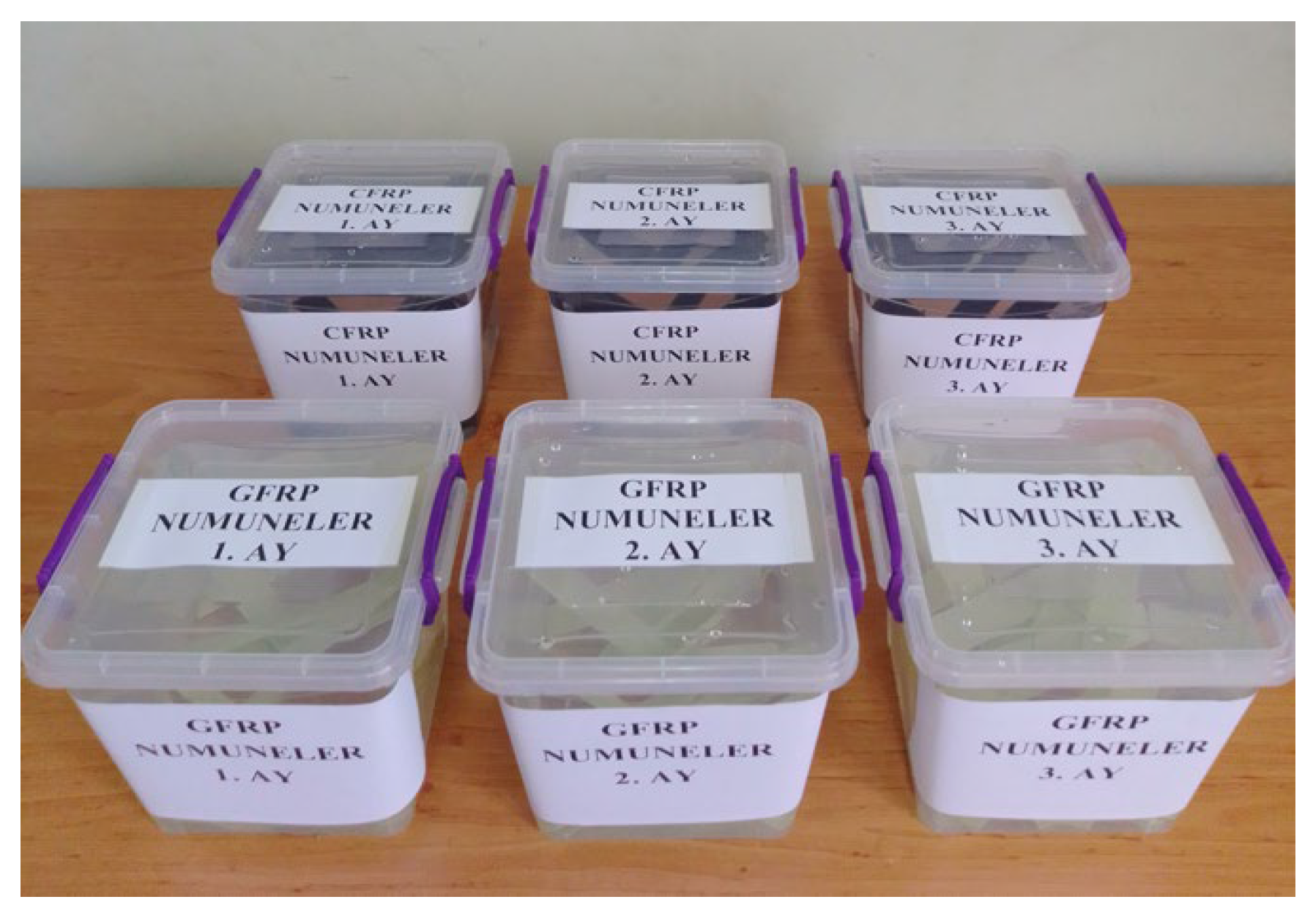
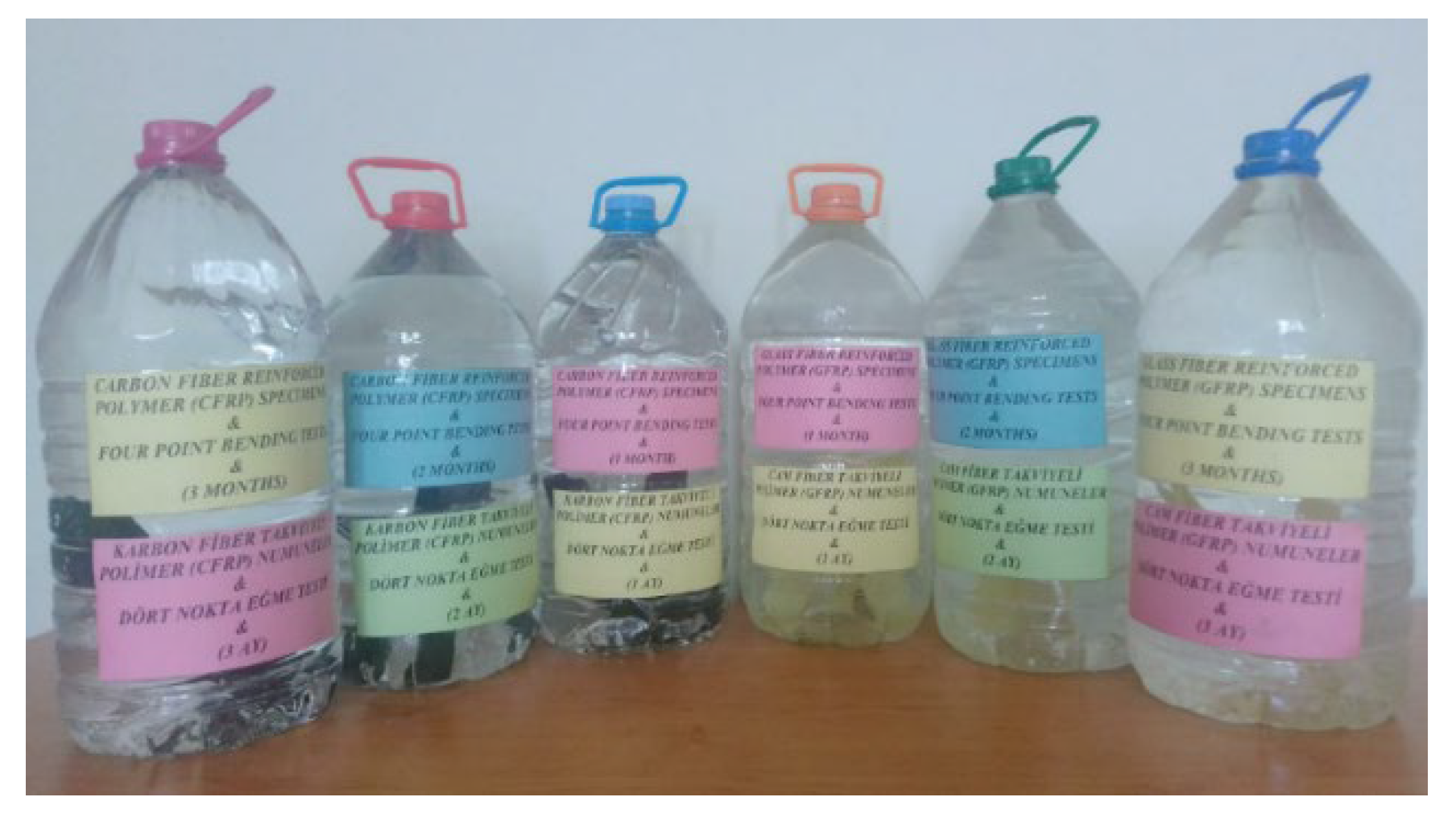
Figure 12.
Soaking GFRP and CFRP samples in sea water for 1, 2 and 3 months for four-point bending tests.
Figure 12.
Soaking GFRP and CFRP samples in sea water for 1, 2 and 3 months for four-point bending tests.
2.1. Comparative Analysis of Three and Four Point Bending Tests on GFRP and CFRP Composites in Marine Environment and Offshore Wind Turbine Blades
Flexural tests are commonly employed to evaluate the mechanical performance of materials and to determine their characteristic properties such as ductility, flexural strength, yield strength, elastic modulus, and fracture toughness. In the three-point bending test, the specimen is supported at both ends, and deformation is observed under a centrally applied load. This method allows the mechanical behavior of materials with different cross-sectional geometries to be analyzed under the assumption of a simple beam model, considering an ideal moment distribution and negligible shear stresses. In contrast, the four-point bending test involves supporting the specimen at both ends and applying two equal loads, thereby creating a constant moment region that enables a detailed examination of both elastic and plastic deformation behaviors.
In this study, the effects of adhesive type, joint geometry, and composite material type on mechanical performance were comprehensively investigated through both three-point and four-point bending tests. In the three-point bending test, the specimen was supported at both ends, and a load applied at the center generated maximum stress; this condition caused the highest stress to occur in the outermost fibers at the midspan of the beam, thus identifying the region most susceptible to failure under bending (Figure 13). This test method is particularly useful for determining the damage mechanisms that occur in the adhesive interface and joint regions of single-lap GFRP and CFRP composite joints aged in marine environments, as well as for analyzing time-dependent variations in their mechanical properties.
On the other hand, the four-point bending test was applied to offshore wind turbine blade composites. The presence of a constant moment region enabled a detailed assessment of the specimen’s elastic and plastic behavior (Figure 14). During this test, the maximum stress and strain values occurring at the center of the adhesive-bonded joint specimens were calculated at each load level, allowing for a reliable evaluation of the mechanical performance of the composite joints. Both testing methods provide a systematic and comprehensive approach to analyzing the behavior of different composite materials and bonding parameters under marine environmental conditions.
The following formula is applied to calculate the amount of stress at a particular point on the load-deflection curve.
- Flexural Stress (σf):
- : stress in the outer fibers at midpoint, MPa
- P: load at a given point on the load-deflection curve, N
- L: support span, mm
- b: width of beam tested, mm
- d: depth of beam tested, mm
- Flexural Strain, εf:
- : strain in the outer surface, mm/mm
- D: maximum deflection of the center of the beam, mm
- L: support span, mm
- D: depth, mm
During the test, the stress and strain values at the center of the adhesively bonded joint specimen were determined at each loading step in the four-point bending test, thus evaluating the material’s mechanical performance.
The following formula is used to calculate the maximum stress value in the area between the loading points in the four-point bending test.
where:
- L: Span between supports, mm
- a the distance between the applied forces, mm
- b: the specimen width, mm
- h: the specimen thickness, mm
- F: applied force, N
Strain, the value is calculated using the following formula:
where:
- : strain, mm/mm
- h: thickness of the specimen, mm
- L: support span, mm
- a: half the loading span, mm
- : deflection at the middle of the span, mm
Both the three-point and four-point bending tests were conducted in the Biomechanics Laboratory of Ege University, Department of Mechanical Engineering, using bending fixtures compatible with a 100 kN capacity Shimadzu AG-100 testing machine. The experiments were performed under a 5 kN load and a crosshead speed of 1 mm/min. All tests were carried out in accordance with the ASTM D790 standard [26] on smooth GFRP and CFRP single-lap joint specimens with an adhesive thickness of 0.2 mm. The specimens were tested under both dry and seawater-conditioned environments to investigate the effects of environmental exposure on mechanical performance.
During the three-point bending tests, stress–strain curves were obtained and analyzed based on the experimental data. In the four-point bending tests, parameters such as applied load, test speed, and specimen geometry were defined on the testing system, and measurements were automatically recorded through the test software.
As a result, the influence of environmental factors on the flexural behavior of the adhesive interface was evaluated for all specimens, and variations in mechanical properties were comparatively analyzed based on the experimental findings. Figure 15 shows the placement of the specimens in the testing machine during both the three-point and four-point bending tests.
A total of 24 connection samples were used within the scope of the experiment, 12 of which were used for the three-point bending test and 12 for the four-point bending test.
3. Results
3.1. Three Point Bending Test Results
3.1.1. GFRP and CFRP Samples
- Dry-Condition Reference Specimens: G-7-K and C-8-K
The damage patterns observed before and after the three-point bending test applied to specimens G-7-K and C-8-K, which were kept in dry conditions, are presented in Figure 15. These specimens were used as a reference for comparison with specimens exposed to seawater.
The dry-condition specimens were stored at 22 °C, isolated from moisture and environmental influences. Therefore, all deformations and damage observed in the specimens are related solely to the bending effects resulting from mechanical loading.
Figure 16a shows that separations occurred along the connection line in specimens G-7-K-1 and G-7-K-2. These separations are believed to be due to tensile stresses concentrated at the specimen ends during the bending test.
Figure 16b also shows that failures initiated at the connection line in specimens C-8-K-2 and C-8-K-3. These failures were caused by the localized effect of the maximum bending stress generated by the applied load in the three-point bending test. Despite this, it was observed that the surface morphology of the CFRP samples largely retained its brightness and smoothness.
- Reference Samples Preserved in Seawater for 1 Month: G-7-1A and C-8-1A
The damage patterns observed before and after the three-point bending test applied to the G-7-1A and C-8-1A specimens, which were stored under dry conditions for one month, are presented in Figure 17. As shown in Figure 17a, no significant fracture occurred along the bonding line in the G-7-1A specimens that were immersed in seawater for one month. Instead, whitish separation traces were observed, particularly in the central regions of the specimens. These whitish zones indicate localized micro-separations at the fiber matrix interface of the GFRP material under the applied bending load. The slight ductility of the GFRP enabled partial absorption of the applied load energy through deformation.
In contrast, as shown in Figure 17b, the C-8-1A-1 and C-8-1A-2 specimens exhibited sudden fractures along the bonding line. The damage observed in the midsection of these specimens indicates a brittle fracture behavior, where load transfer was abruptly interrupted. However, in the C-8-1A-3 specimen, a portion of the adhesive layer remained attached to the specimen surface, suggesting that the interfacial bond was not completely broken and that partial load transfer continued.
- Reference Samples Stored in Seawater for 2 Months: G-7-2A and C-8-2A
For the G-7-2A and C-8-2A specimens, which were kept for two months, different damage behaviors were observed after the three-point bending tests.
In the G-7-2A series shown in Figure 18a, the G-7-2A-1 specimen exhibited no significant fracture after the test and remained largely intact structurally, indicating that the bonding integrity was maintained. The G-7-2A-2 specimen showed a more pronounced fracture surface along the bonding line, where part of the adhesive material had detached from the interface. The G-7-2A-3 specimen, on the other hand, failed at the bonding region, exhibiting both fracture and localized deformation behavior. Especially in the edge regions of the G-7-2A-2 and G-7-2A-3 specimens, adhesive separation and weakened adhesion were observed.
In Figure 18b, the C-8-2A-1 specimen generally preserved its surface integrity, though localized cracking occurred in the bonding region. The C-8-2A-2 specimen showed partial degradation of the bond between the laminate and the adhesive; adhesive separation and void formations were evident on the surface. This suggests that the adhesive layer was more affected by environmental exposure. In the C-8-2A-3 specimen, distinct adhesive residues were observed along the bonding line.
- Reference Samples Stored in Seawater for 3 Months: G-7-3A and C-8-3A
As shown in Figure 19a, the G-7-3A series exhibited various fracture types. In the G-7-3A-1 specimen, fracture propagated directly along the bonding line, indicating a complete loss of adhesion in this region. The G-7-3A-2 specimen showed surface-level adhesive failure due to insufficient bonding between the adhesive and the substrate surfaces. The G-7-3A-3 specimen exhibited a mixed fracture pattern, with both interfacial failure and visible adhesive residues on the surfaces. While the first two specimens showed damage concentrated on the upper surfaces, the third specimen displayed fracture spreading across both surfaces.
In Figure 19b, the C-8-3A-1 specimen showed separation over a large portion of the adhesive layer but largely retained its structural integrity. The C-8-3A-2 specimen displayed the most distinct signs of fracture and delamination in the bonding region. In the C-8-3A-3 specimen, some adhesive remained on the surface, indicating that the bonding effect was not completely lost.
The stress-strain results presented in Figure 20 were obtained from three-point bending tests performed after storage of GFRP composite specimens in dry conditions and in seawater for 1, 2 and 3 months.
The Elastic Modulus, also known as Young’s Modulus, is a fundamental mechanical property that defines how elastic or rigid a material behaves under external loads. This modulus is considered a quantitative indicator of a material’s stiffness. Materials with a high Young’s Modulus deform very little under applied force, indicating that they are stiffer and more rigid. Conversely, materials with a low elastic modulus tend to deform more under the same load and are therefore regarded as more flexible [32]. Here, the elastic modulus (E) values were calculated from the slope of the linear (elastic) regions of the stress–strain (σ–ε) curves. The elastic modulus values presented in Table 4 were obtained from the slope of the linear portion of the stress–strain data shown in Figure 20 and, similarly, from the slope of the linear portion of the data shown in Figure 21.
According to Table 4, the Young’s (Elastic) Modulus values of the GFRP and CFRP composite specimens are presented comparatively. The results indicate that the elastic modulus of the CFRP specimens is significantly higher than that of the GFRP specimens, demonstrating that CFRP possesses a more rigid and durable structure.
For both material types, a decrease in the elastic modulus was observed as the exposure time to seawater increased. However, this reduction was more pronounced in the GFRP specimens, while it was relatively limited in the CFRP specimens. This suggests that CFRP exhibits more stable mechanical properties against moisture and environmental effects.
Overall, Table 4 reveals that CFRP has a higher elastic modulus and better environmental resistance compared to GFRP, making it a more suitable material for challenging conditions such as marine environments.
3.2. Four Point Bending Test Results
3.2.1. GFRP and CFRP Samples
- Dry Condition Reference Samples: GFRP-7L-FPBT-DE-1S and CFRP-8L-FPBT-DE-1S
In Figure 22a, it was observed that in the GFRP-7L-FPBT-DE-1S specimens, the damage initially started at the bond line and propagated toward the surfaces. In the regions where the separations were concentrated, fine cracks and partial delaminations progressing along the adhesive interfaces were detected. This indicates that the stress within the material accumulated in a specific region, exceeding the strength limit of the bond line. As the damage progressed, the interlaminar separation increased; however, the overall structural integrity of the specimen was maintained. This demonstrates that the failure occurred gradually rather than abruptly.
In the CFRP-8L-FPBT-DE-1S specimens shown in Figure 22b, a similar fracture pattern was observed. The separation generally initiated along the bond line and propagated toward the surface layers. In some specimens, parts of the adhesive remained on the opposite surfaces, indicating that adhesion was locally maintained. The concentration of damage in a specific area reveals that load transfer along the bond line was not uniform, and stress concentration in that region played a significant role.
- Reference Samples Preserved in Seawater for 1 Month: 1GFRP-7L-FPBT-1M and CFRP-8L-FPBT-1M
In the GFRP-7L-FPBT-1M specimens shown in Figure 23a, a significant weakening was observed at the bond interface due to the influence of seawater. The prolonged exposure to the saline environment caused ions, along with water molecules, to diffuse into the adhesive layer, which weakened the chemical bonds and disrupted the adhesive integrity at the microscopic level. The accumulation of moisture and ions at the interface reduced the mechanical strength of the adhesive, leading to localized delaminations and the formation of microcracks. As a result of these effects, the adhesion strength along the bond line of the GFRP-7L-FPBT-1M specimens decreased, and fracture typically initiated in these regions.
In the CFRP-8L-FPBT-1M specimens shown in Figure 23b, a different damage mechanism was observed. The low water absorption capacity of carbon fiber-reinforced composites significantly limited the penetration of seawater into the interface. Consequently, the bond between the adhesive and the composite surface maintained its stability for a longer period. However, when fracture occurred, it was sudden and brittle in nature. This behavior is attributed to the high elastic modulus and tensile strength of carbon fibers along the fiber direction. Therefore, although the fracture load of the CFRP-8L-FPBT-1M specimens was higher compared to that of the GFRP-7L-FPBT-1M specimens, the failure occurred more abruptly.
- Reference Samples Stored in Seawater for 2 Months: GFRP-7L-FPBT-2M and CFRP-8L-FPBT-2M
In the GFRP-7L-FPBT-2M specimens shown in Figure 24a, it was observed that the damage was not limited to the adhesive bond line but also involved adhesive residues on both surfaces. This indicates that the fracture occurred both within the adhesive layer and at the bond interface, revealing a mixed failure mode consisting of cohesive and adhesive fractures. During loading, the adhesive layer along the bond line began to lose its internal structural strength; simultaneously, the reduction in interfacial adhesion forces caused the layers to separate from each other. This distribution of damage demonstrates that the stress along the bonding line was not uniformly distributed and that local stress concentrations developed. In addition, prolonged exposure to seawater caused both chemical degradation and physical weakening along the bond line, leading to a mixed-mode fracture progression.
In the CFRP specimens shown in Figure 24b, a similar type of damage was identified. The occurrence of adhesive residues on both surfaces, along with fracture within the adhesive layer, indicates that cohesive and adhesive failures developed simultaneously. However, a noteworthy observation is that in the CFRP-8L-FPBT-2M specimens, the fiber-reinforced structure allowed for a more balanced load transfer along the bond line. The high elastic modulus and low water absorption property of the carbon fibers limited seawater penetration into the adhesive region, contributing to the preservation of bonding quality. Therefore, despite two months of seawater exposure, the bond line strength of the CFRP-8L-FPBT-2M specimens was largely maintained, and fracture occurred in a more controlled manner.
- Reference Samples Stored in Seawater for 3 Months: GFRP-7L-FPBT-3M and CFRP-8L-FPBT-3M
In the GFRP-7L-FPBT-3M specimens shown in Figure 25a, which were immersed in seawater for three months, the damage was found to develop directly along the bond line. It was observed that the fracture was concentrated mainly in the central region of the joint, where the adhesive partially remained attached to both surfaces. This indicates that the damage primarily occurred within the adhesive layer and that the bond interface had weakened. The penetration of ions and moisture from seawater into the adhesive layer caused degradation and plasticization of the polymer structure. This effect led to the formation of microscopic voids and structural discontinuities at the interface, reducing the mechanical strength of the bonding line. As a result, the bond strength of the GFRP-7L-FPBT-3M specimens decreased, and fracture occurred at lower load levels.
In the CFRP-8L-FPBT-3M specimens presented in Figure 25b, a similar damage pattern was observed, although the severity of the damage was more limited. After the fractures developed along the bonding line, the presence of adhesive residue on both surfaces indicated that cohesive and adhesive failures occurred simultaneously. However, due to the high fiber strength and low water absorption capacity of the CFRP-8L-FPBT-3M specimens, seawater penetration into the interfacial region was significantly reduced, and the bonding quality was largely preserved. Therefore, despite prolonged seawater exposure, the CFRP-8L-FPBT-3M specimens maintained their structural integrity and exhibited higher bond strength compared to the GFRP-7L-FPBT-3M specimens.
Figure 26 presents the stress–strain results obtained from four-point bending tests conducted on GFRP composite specimens after being stored in dry conditions and in seawater for 1, 2, and 3 months.
Here, the elasticity modulus (E) values were calculated from the slope of the linear (elastic) regions of the stress–strain (σ–ε) curves. The elasticity modulus values presented in Table 7 were obtained from the slope of the linear portion of the stress–strain data shown in Figure 28 and, similarly, from the linear portion of the data presented in Figure 29.
According to Table 7, a gradual decrease in the elasticity modulus was observed for both GFRP and CFRP specimens as the seawater exposure duration increased. This decrease was more pronounced in the GFRP specimens compared to the CFRP ones. In particular, the reduction in the elasticity modulus of the G-7 series reached approximately 13% after three months of exposure, indicating the influence of water absorption in the matrix and the weakening of the fiber–matrix interfacial bonding. In contrast, the reduction in the CFRP specimens remained within the range of 3–4%, demonstrating that carbon fibers exhibit a more resistant structure against moisture. These results reveal that CFRP maintains its mechanical stability under marine environmental conditions better than GFRP.
The data presented in Table 8 include a comparative evaluation of the results obtained from three-point and four-point bending tests. Based on this comparison, Table 9 provides a performance analysis of the results from both testing methods, highlighting the differences in load-bearing capacity and deformation behavior of the specimens.
3.3. Damage Analysis of GFRP and CFRP Specimens in Three-Point and Four-Point Bending Tests
The three-point bending test is a widely used method for examining the flexural strength, fracture behavior, and interfacial interactions of composite materials. This test reveals the stress distribution in the tensile and compressive regions of the material, allowing for the evaluation of damage mechanisms, particularly at the fiber–matrix interface.
However, the four-point bending test generates a wider pure bending region, enabling a more homogeneous examination of stress distribution along the material and providing more comprehensive information about interfacial strength and the overall integrity of the laminate structure.
As the duration of seawater exposure increases, interlaminar delamination, fiber–matrix bond weakening, and damage development in the bonded regions become more pronounced in both tests. Such damage depends on multiple factors, including the microstructural characteristics of the material, the type of joint, and the chemical properties of the adhesive used. Therefore, microstructural analyses supported by three- and four-point bending tests are crucial for accurately assessing the performance changes of composite materials in marine environments.
SEM images of GFRP specimens after three-point bending, stored in dry conditions and in seawater for different durations (1, 2, and 3 months), are presented in Figure 24, while SEM images of CFRP specimens after three-point bending tests are shown in Figure 25. SEM images of GFRP specimens after four-point bending, under dry conditions and seawater exposure for 1, 2, and 3 months, are presented in Figure 26, and SEM images of CFRP specimens after four-point bending tests are shown in Figure 27.
3.3.1. SEM Analysis of GFRP Specimens After Three-Point Bending Test
In Figure 28a, for the GFRP specimens stored under dry conditions, i.e., without exposure to seawater, the three-point bending test revealed local fiber breakages and limited fiber pull-outs as the load increased. Such damage results from the fibers in the tensile and compressive regions being subjected to different stress levels under the applied bending load [33]. Since the specimens were in a dry environment, no chemical degradation, swelling, or structural weakening occurred at the fiber–matrix interface, and therefore, the interfacial bonding strength was largely preserved. This indicates that strong load transfer between the fibers and the matrix was maintained.
In Figure 28b, for specimens exposed to seawater for 1 month, the slow diffusion of water into the matrix caused weakening and microscale degradation at the fiber–matrix interface. Ionic components in seawater chemically interacted with the epoxy matrix, reducing the bond strength and creating microvoids and detachments at the interface. This process led to fiber breakage under load and the formation of microcracks on the matrix surface. A slight increase in surface roughness was observed, making the material more susceptible to further water absorption in subsequent stages.
In Figure 28c, for specimens exposed to seawater for 2 months, deeper penetration of water into the layers significantly weakened the fiber–matrix interaction, and structural integrity began to deteriorate. At this stage, fiber fractures, matrix cracks, and delamination damage were clearly observed. Water progression at the fiber–matrix interface facilitated crack propagation. Moreover, SEM images showed that the surface had become more irregular compared to earlier stages, with an increase in microscale pits and fracture traces. This contributed to a reduction in mechanical strength.
In Figure 28d, for specimens exposed to seawater for 3 months, extensive damage developed as moisture reached saturation within the material. Pronounced separations occurred at the fiber–matrix interface, with voids and swelling forming around fiber bundles. Fiber breakages and crack propagation combined under load to create macro-scale delamination regions. Additionally, chemical degradation and water-induced swelling in the matrix significantly reduced interfacial bonding strength, leading to a considerable decline in the overall mechanical performance of the material. Although water absorption slowed in later stages, the structural degradation process did not stop; instead, the existing damage expanded and merged, further compromising the integrity of the material.
3.3.2. SEM Examination of CFRP Specimens After Three-Point Bending Test
In Figure 29a, for CFRP specimens stored under dry conditions (without exposure to seawater), the fibers were observed to be regularly aligned and exhibited strong bonding with the epoxy matrix. The matrix phase formed a homogeneous and continuous structure, with no voids, bubbles, or interfacial separations detected between the fiber bundles. However, as a result of the applied three-point bending load, local fiber breakages and fractures occurred in regions where load transfer was most concentrated. These fractures developed due to the high stresses experienced by the fibers in the tensile regions.
In Figure 29b, for specimens exposed to seawater for 1 month, initial signs of microstructural changes were observed, indicating the onset of early damage. Diffusion of seawater into the matrix caused microscale irregularities on the matrix surface, slight swelling, and increased surface roughness. Softening of the epoxy matrix occurred with water absorption, and microscopic separations at the fiber–matrix interface were detected. Small voids around the fibers partially weakened load transfer and resulted in limited fiber breakages. At this stage, the observed damage remained largely superficial due to the restricted penetration of water into the matrix.
In Figure 29c, for specimens exposed to seawater for 2 months, the damage types became more pronounced, and various microstructural deformations appeared in the material. Seawater penetration into the matrix weakened the chemical bonding of the epoxy chains, leading to the development of microcracks and localized deterioration. Wider separation zones were detected at the fiber–matrix interfaces, and in some areas, fiber bundles began to detach from the surface. Additionally, capillary-driven water movement along the interface resulted in the formation of micropores and bubbles.
In Figure 29d, for specimens exposed to seawater for 3 months, microstructural deterioration reached an advanced stage. Pronounced cracks, localized delaminations, and surface peeling occurred in the matrix phase. The size of the separations at the fiber–matrix interface increased, with some carbon fibers protruding from the matrix and exposed at the surface. Prolonged seawater exposure led to the development of micropores and capillary voids within the matrix, facilitating water penetration into the interior and accelerating the damage process.
3.3.3. SEM Analysis of GFRP Specimens After Four-Point Bending Test
In Figure 30a, the SEM images of the GFRP control specimen stored under dry conditions show strong bonding between the glass fibers and the polymer matrix. The fibers are evenly distributed, with minimal voids between them, and the fiber–matrix interface maintains its continuity. The absence of cracks or fracture traces in the fibers indicates that the specimen’s flexural strength remains high.
In Figure 30b, for specimens exposed to seawater for 1 month, weakening of the bond between fibers and matrix is noticeable. Interfacial separations and fiber pull-outs occur, while microcracks and localized plastic deformations are observed on the matrix surface. Penetration of water molecules from seawater into the matrix causes swelling and stress accumulation in the material, reducing the interfacial bonding strength. Although the mechanical properties have decreased compared to the dry condition, the structural integrity is partially preserved.
In Figure 30c, for GFRP specimens exposed to seawater for 2 months, microstructural deterioration becomes more pronounced. Fiber breakages and shrinkages, along with numerous microcracks, voids, and fragmented areas within the matrix, are observed. Fiber–matrix interaction is largely lost, and interfacial bond failure limits load transfer. This results in reduced flexural strength and the emergence of brittle behavior in the specimen.
In Figure 30d, for specimens exposed to seawater for 3 months, the microstructural integrity is almost completely lost. The fibers have detached from the matrix, becoming free, and severe chemical degradation has occurred in the polymer matrix. Microscale cracks have coalesced into macroscopic fractures over time, leading to sudden and brittle failure. The mechanical strength of the matrix has been significantly reduced due to water exposure.
3.3.4. SEM Analysis of CFRP Specimens After Four-Point Bending Test
In Figure 31a, the SEM images of the CFRP control specimen stored under dry conditions show strong bonding between the fibers and the matrix. The fibers are properly embedded in the matrix, exhibiting a regular structure and high interfacial integrity at the fracture surface. Some fiber pull-out is observed, but overall the fracture occurs in a balanced manner. This indicates that energy during mechanical loading is dissipated in a ductile way, and the fracture occurs in a controlled rather than sudden manner.
In Figure 31b, for CFRP specimens exposed to seawater for 1 month, initial microstructural deterioration is observed. Local separations appear in the interfacial regions, and microcracks and deformation traces become noticeable on the matrix surface. These changes indicate that the fiber–matrix bonds are beginning to weaken, and the mechanical properties of the specimen show a decreasing trend.
In Figure 32c, after two months of seawater exposure, structural deterioration becomes more advanced. Fibers detach from the matrix, and swelling, cracking, and voids become more pronounced in the resin phase. The fiber fractures appear short and irregular, indicating that the fracture surface is gradually gaining a more brittle character.
In Figure 33d, after three months of seawater exposure, the microstructural integrity is significantly weakened. Bonds at the fiber–matrix interface are largely loosened, and delamination and void formation in the resin layer are increased. These developments result in a considerable reduction in the mechanical strength of the composite structure. Table 6 presents a comparison of the SEM results for GFRP and CFRP specimens after three-point and four-point bending tests.

Table 6.
Comparison of SEM Results from Three-Point and Four-Point Bending Tests.
| Condition | GFRP (Three-Point Bending) | GFRP (Four-Point Bending) | CFRP (Three-Point Bending) | CFRP (Four-Point Bending) |
|---|---|---|---|---|
| Dry Environment (Reference) | Local fiber fractures and limited pull-outs were observed. No chemical degradation or swelling occurred. The fiber–matrix bond is strong, and load transfer is effective. | The fiber–matrix interface is strong. Fibers are evenly distributed with a low void content. The fracture exhibited ductile behavior. | The fibers are observed to be regularly aligned, and the matrix is homogeneous. Fiber breakages at the interface are limited. | The fiber–matrix interface exhibits high integrity. Fibers are firmly bonded to the matrix, and fracture occurs in a controlled manner. |
| Samples Soaked in Seawater for 1 Month |
Diffusion of water into the matrix weakened the interface, leading to the formation of microcracks and voids. Surface roughness has increased. |
Degradation has begun in the fiber–matrix bonds. Microcracks and plastic deformations are observed. | Irregularities and swelling are observed on the matrix surface. Microscopic separations have begun at the fiber–matrix interface.. | Local separations and microcracks have formed at the interface. Matrix deformations have become pronounced, and bond strength has decreased. |
| Samples Soaked in Seawater for 2 Months |
Fiber–matrix interaction has weakened, with increased delamination and microcracks. The surface has become irregular. | Microstructural deterioration has become pronounced. Fiber fractures and void formation are observed. | The chemical bonds have weakened, leading to the formation of microcracks and surface separations. Fiber bundles have partially detached. | Fibers have detached from the matrix, and swelling and voids in the resin phase have intensified. The fracture behavior has become more brittle. |
| Samples Soaked in Seawater for 3 Months |
Pronounced separations and voids have formed at the fiber–matrix interface. Fiber fractures have coalesced, creating delamination regions. | The microstructural integrity is largely lost. Fibers have become free, and the matrix has undergone chemical degradation. | Matrix cracks and surface peeling have increased. Some fibers have lost their adhesion to the matrix. | Fiber–matrix bonds have separated, and delamination and voids in the resin structure have become pronounced. Mechanical strength has decreased significantly. |
SEM analyses revealed that, in both GFRP and CFRP specimens, microstructural deterioration became increasingly pronounced as the duration of seawater exposure increased. Under dry conditions, high interfacial integrity and strong fiber–matrix interaction were observed. However, starting from the first month of exposure, interfacial degradation, microcracks, and void formation occurred due to water diffusion into the interface. This process led to increased chemical degradation and stress accumulation in the matrix, weakening the interfacial bonding.
During the two- and three-month aging periods, both glass fiber (GFRP) and carbon fiber (CFRP) specimens exhibited reduced fiber adhesion to the matrix, expansion of delamination regions, and a shift in fracture behavior from ductile to brittle. In GFRP specimens, deterioration primarily manifested as matrix deformation and interfacial debonding, whereas in CFRP specimens, microvoid formation and surface separations became more pronounced.
In four-point bending tests, the wider load transfer regions allowed structural damage to distribute more evenly, while in three-point bending tests, stress concentration at a single point caused damage to occur more locally and suddenly. Consequently, prolonged seawater exposure weakened the fiber–matrix bond strength, disrupted microstructural integrity, and led to a significant reduction in flexural strength in both GFRP and CFRP composites.
4. Discussion and Conclusions
The strength of adhesively bonded single-lap GFRP and CFRP joints used in marine environments, particularly in offshore wind turbine blades, is critically dependent on long-term exposure to seawater. Existing studies have generally been conducted under single-material conditions and limited environmental scenarios, leaving the effects of different composite types and seawater exposure largely unexplored.
In this study, GFRP and CFRP specimens were stored both under dry conditions and in natural seawater collected from the Aegean Sea (22 °C, 3.3–3.7% salinity) for 1, 2, and 3 months. Their mechanical behavior and damage characteristics were comparatively evaluated through three-point and four-point bending tests.
Results from the three-point bending tests showed that the Young’s modulus of GFRP decreased by approximately 13% after 3 months of seawater exposure, whereas the reduction in CFRP was limited to only 3.7%. In GFRP, micro-separations, partial fiber pull-outs, and matrix deformation were observed, while CFRP exhibited minimal damage, maintaining better structural strength. SEM analyses revealed that, in both materials, damage initiated in the matrix phase before propagating to the fiber phase, with CFRP maintaining a more uniform fiber–matrix interfacial bond compared to GFRP.
A similar trend was observed in the four-point bending tests. GFRP’s Young’s modulus decreased by 9.5%, whereas the reduction in CFRP remained limited to 3.5%. In GFRP, cracks and layer delaminations progressed gradually, whereas CFRP demonstrated more homogeneous load transfer and controlled fracture. Seawater exposure in GFRP led to interfacial weakening and microvoid formation, whereas the adhesive–layer bond in CFRP remained largely intact, resulting in fracture at higher load levels. The use of F-RES 21 epoxy resin and F-Hard 22 hardener contributed to preserving structural integrity in both material groups.
Overall, both three-point and four-point bending tests demonstrated that CFRP joints are more resistant to seawater exposure compared to GFRP, offering higher mechanical strength and structural stability. While stress concentration at a single point in three-point bending led to local and sudden damage, the broader load transfer in four-point bending allowed for more uniform distribution of damage.
Author Contributions
D.M.Y.: Project Administration, Conceptualization, Validation, Formal Analysis, Methodology; G.A.: Writing—Original Draft Preparation, Writing—Review and Editing, Data Curation, Investigation, Resources, Visualization. All authors have read and agreed to the published version of the manuscript.
Funding
This research received no external funding.
Institutional Review Board Statement
Not applicable.
Informed Consent Statement
Not applicable.
Data Availability Statement
The original contributions presented in the study are included in the article, further inquiries can be directed to the corresponding author.
Conflicts of Interest
The authors declare no conflict of interest.
References
- Mallick, P. K. (2007). Fiber-reinforced composites: materials, manufacturing, and design. CRC press.
- Khoo, P. S., Ilyas, R. A., Jamal, T., Gan, C. S., Yu, J. M., Ikram, M. A. A. M., ... & Mahardika, M. (2025). Sugar Palm (Arenga pinnata): Newly Discovered Natural Fiber with Its Properties and Applications. ChemBioEng Reviews, e70010.
- Alam, M. N., & Kumar, V. (2025). Multifunctional Polymer Composite Materials. Polymers, 17(21), 2847.
- Motta de Castro, E., Tabei, A., Cline, D. B., Haque, E., Chambers, L. B., Song, K., ... & Asadi, A. (2025). New insights in understanding the fiber-matrix interface and its reinforcement behavior using single fiber fragmentation data. Advanced Composites and Hybrid Materials, 8(1), 5.
- Abodunrin, O. W., & Ajayi, A. A. (2025). Electrical Characterization, Optical Micrographs, and the Compositional Analyses of Al-Glass/C-Glass Composites. Advanced Materials & Sustainable Manufacturing, 2(4), 10014.
- Daniel, I. M., Ishai, O., Daniel, I. M., & Daniel, I. (1994). Engineering mechanics of composite materials (Vol. 3, pp. 256-256). New York: Oxford university press.
- Chen, Y., Guo, J., & Guo, W. (2025). 2D to 3D Modification of Chang–Chang Criterion Considering Multiaxial Coupling Effects in Fiber and Inter-Fiber Directions for Continuous Fiber-Reinforced Composites. Polymers, 17(17), 2416.
- Motta de Castro, E., Tabei, A., Cline, D. B., Haque, E., Chambers, L. B., Song, K., ... & Asadi, A. (2025). New insights in understanding the fiber-matrix interface and its reinforcement behavior using single fiber fragmentation data. Advanced Composites and Hybrid Materials, 8(1), 5.
- Agarwal, B. D., Broutman, L. J., & Chandrashekhara, K. (2017). Analysis and performance of fiber composites. John Wiley & Sons.
- Saylık, A., & Temiz, Ş. (2025). DRY SLIDING WEAR RESISTANCE OF AGED WOVEN CARBON AND GLASS FIBER-REINFORCED EPOXY MATRIX COMPOSITES IN DIFFERENT DEGRADATION ENVIRONMENTS. Konya Journal of Engineering Sciences, 13(3), 947-964.
- Zhang, C., & Chen, H. P. (2024). Monitoring based fatigue damage prognosis of wind turbine composite blades under uncertain wind loads. arXiv preprint arXiv:2404.10021.
- Shao, Z., Liu, Z., Liang, J., Liu, H., & Zhang, Y. (2024). Fatigue Reliability Modelling and Assessment of Carbon Fiber Reinforced Polymer/Epoxy Resin Bonded Structure Incorporating Multiple Environmental Stresses and Size Effects. Modelling, 5(3), 1116-1134.
- Nas, I., Turan, K., AŞAN, A. M., & ÖRÇEN, G. (2025). Long-term sea water effect on the failure behaviour of adhesively strap joints. Journal of Composite Materials, 00219983251370397.
- Hamzat, A. K., Murad, M. S., Adediran, I. A., Asmatulu, E., & Asmatulu, R. (2025). Fiber-reinforced composites for aerospace, energy, and marine applications: an insight into failure mechanisms under chemical, thermal, oxidative, and mechanical load conditions. Advanced Composites and Hybrid Materials, 8(1), 152.
- Choudhari, P., Kulkarni, V., & Khandal, S. (2024). Review on efforts to improve the mechanical performance of Fiber-Reinforced Polymer (FRP) composites under the Marine Environment. Journal of The Institution of Engineers (India): Series C, 105(1), 241-269.
- Shi, J. W., Li, H. Y., Cao, W. H., & Wang, H. T. (2025). Fatigue behavior and bond improvement of the FRP-to-concrete interface after marine corrosion. Engineering Structures, 332, 120043.
- Patro, B. P. , Sahoo, B. P., Pradhan, S. K., Dash, M., Rath, P., & Das, D. (2025). Effects of sea water aging and cold treatment on properties and three-body abrasion behaviour of FRP composites: Regression analysis, ANOVA and GRA embedded VIKOR multi-response optimization. Proceedings of the Institution of Mechanical Engineers, Part C: Journal of Mechanical Engineering Science, 09544062251378654.
- Choudhari, P. , Kulkarni, V., & Khandal, S. (2024). Review on efforts to improve the mechanical performance of Fiber-Reinforced Polymer (FRP) composites under the Marine Environment. Journal of The Institution of Engineers (India): Series C, 105(1), 241-269.
- Hamzat, A. K. , Murad, M. S., Adediran, I. A., Asmatulu, E., & Asmatulu, R. (2025). Fiber-reinforced composites for aerospace, energy, and marine applications: an insight into failure mechanisms under chemical, thermal, oxidative, and mechanical load conditions. Advanced Composites and Hybrid Materials, 8(1), 152.
- Azhar, A. , Pribadi, T. W., Widodo, A. B., & Nugroho, N. Y. (2025). Mechanical Characteristics of Glass Fibre Vessels. International Journal of Marine Engineering Innovation and Research, 10(3), 652-661.
- Rubino, F. , Nisticò, A., Tucci, F., & Carlone, P. (2020). Marine application of fiber reinforced composites: a review. Journal of Marine Science and Engineering, 8(1), 26. [CrossRef]
- Teng, H. , Li, S., Cao, Z., Li, S., Li, C., & Ko, T. J. (2023). Carbon fiber composites for large-scale wind turbine blades: Applicability study and comprehensive evaluation in China. Journal of Marine Science and Engineering, 11(3), 624.
- Ennis, B. L. , Kelley, C. L., Naughton, B. T., Norris, R. E., Das, S., Lee, D., & Miller, D. (2019). Optimized carbon fiber composites in wind turbine blade design (No. SAND-2019-14173). Sandia National Lab.(SNL-NM), Albuquerque, NM (United States); Oak Ridge National Lab.(ORNL), Oak Ridge, TN (United States).
- Nixon-Pearson, O. , Greaves, P., Mamalis, D., & Stevenson, L. (2022). WP4–D1. 1. wind turbine blades design and manufacturing, current state-of-the art. Report-Cornwall flow accelarator, 1-94.
- Steigmann, R. , Iftimie, N., Savin, A., & Sturm, R. (2016). Wind turbine blade composites assessment using non-contact ultrasound method. J. Clean Energy Technol, 4, 440-443.
- Papadakis, N. , & Condaxakis, C. (2024). An Experimental Performance Assessment of a Passively Controlled Wind Turbine Blade Concept: Part B—Material Oriented with Glass-Fiber-Reinforced Polymer. Energies, 17(13), 3286.
- Critchfield, M. O. , Judy, T. D., & Kurzweil, A. D. (1994). Low-cost design and fabrication of composite ship structures. Marine structures, 7(2-5), 475-494.
- Caramatescu, A. , & Mocanu, C. I. (2019). Review of composite materials applications in marine industry. Annals of” Dunarea de Jos” University of Galati. Fascicle XI Shipbuilding, 42, 169-174.
- Crupi, V. , Epasto, G., Napolitano, F., Palomba, G., Papa, I., & Russo, P. (2023). Green composites for maritime engineering: a review. Journal of Marine Science and Engineering, 11(3), 599.
- ASTMD5868-01; Standard Test Method for Lap Shear Adhesion for Fiber Reinforced Plastic (FRP) Bonding. ASTM International: West Conshohocken, PA, USA, 2023.
- Croccolo, D.; De Agostinis, M.; Fini, S.; Olmi, G. Influence of the engagement ratio on the shear strength of an epoxy adhesive by push-out tests on pin-and-collar joints: Part I: Campaign at room temperature. Int. J. Adhes. Adhes. 2016, 67, 69–75. [Google Scholar] [CrossRef]
- Vaidya, A. , & Pathak, K. (2019). Mechanical stability of dental materials. In Applications of nanocomposite materials in dentistry (pp. 285-305). Woodhead Publishing.
- Callister Jr, W. D. , & Rethwisch, D. G. (2020). Materials science and engineering: an introduction. John wiley & sons.
Figure 1.
Material types according to structural components of wind turbine blade [25].
Figure 1.
Material types according to structural components of wind turbine blade [25].
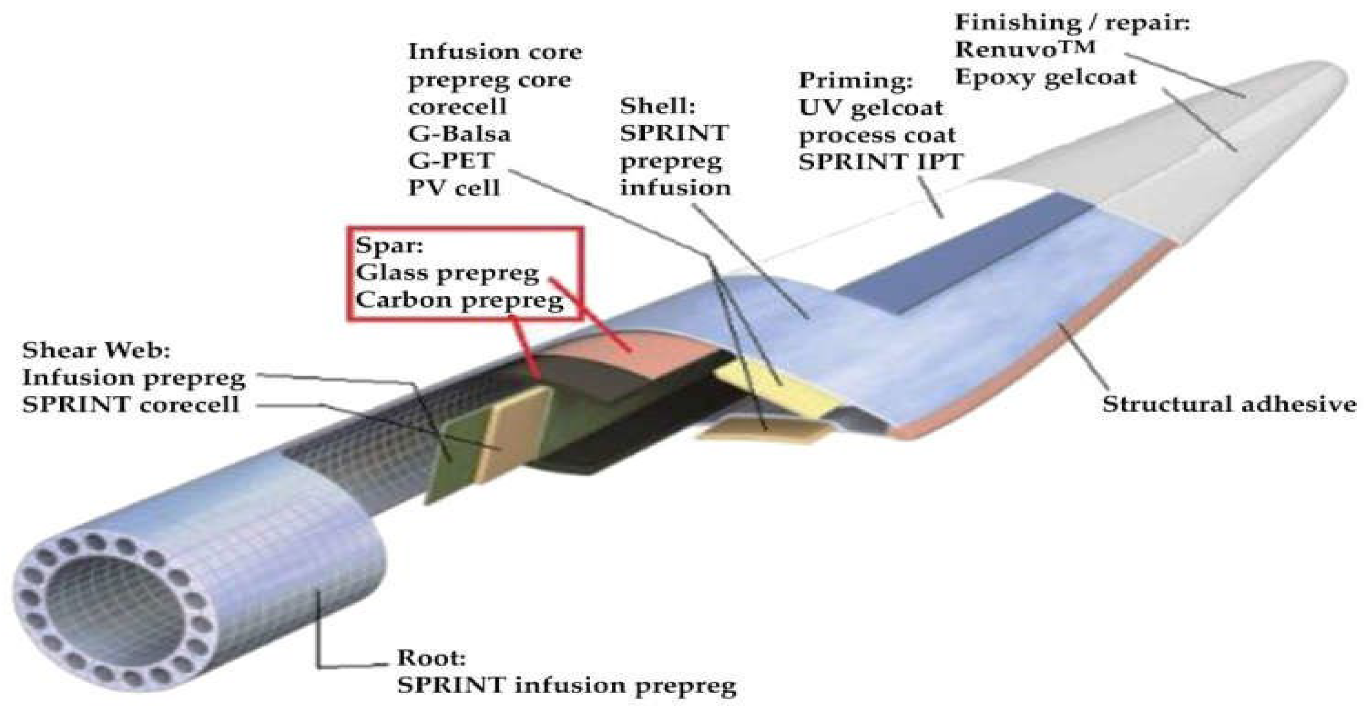
Figure 2.
Applications of composite materials used in marine vessels [27].
Figure 2.
Applications of composite materials used in marine vessels [27].
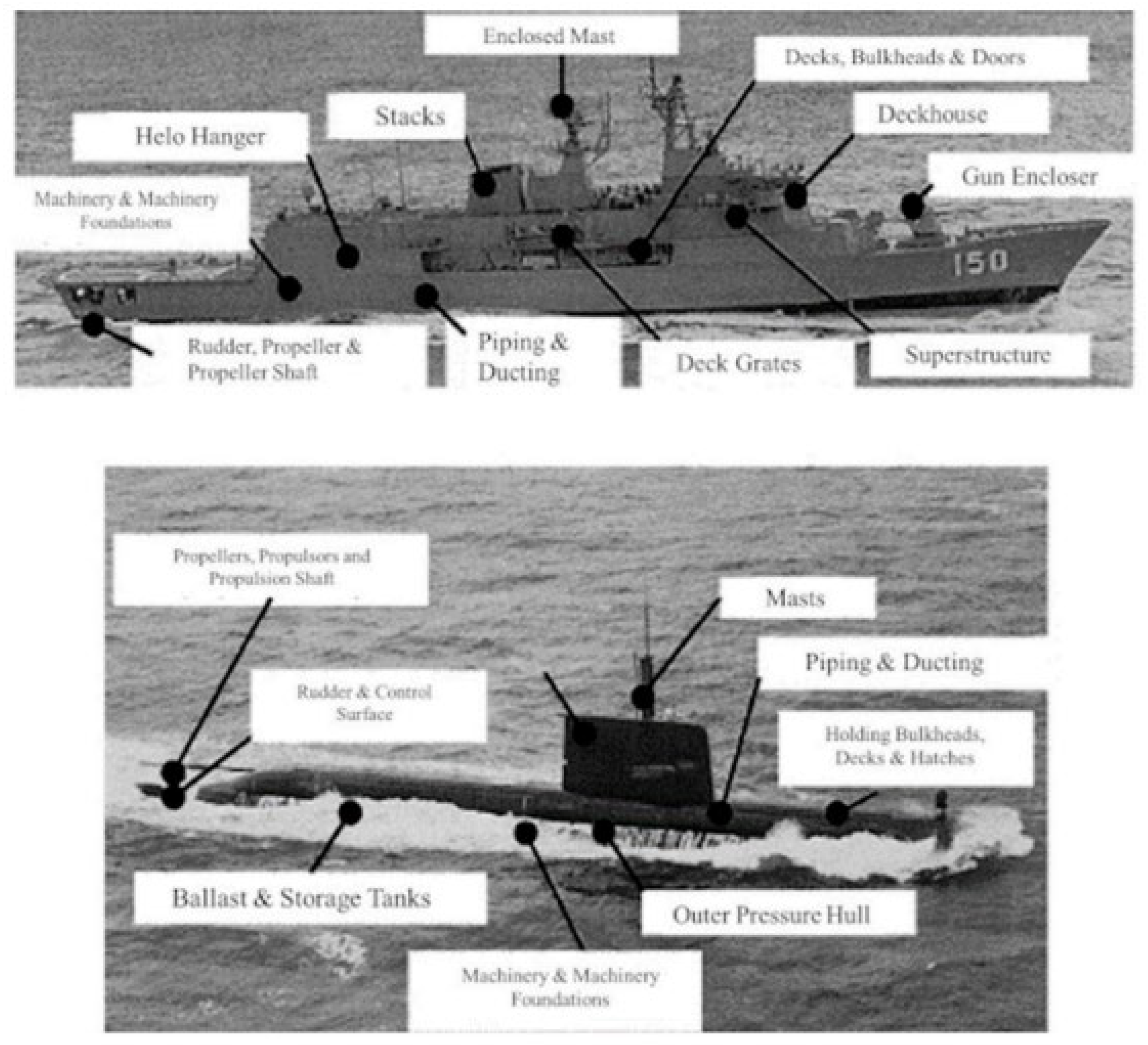
Figure 3.
Machining of GFRP and CFRP Samples by CNC Router.
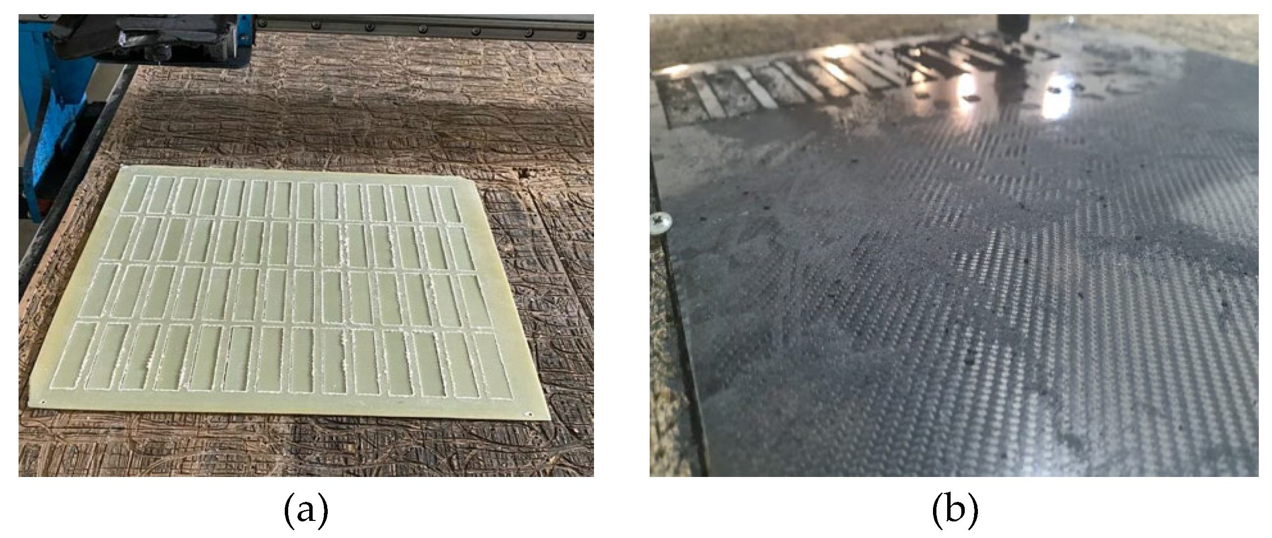
Figure 4.
Schematic Representation of GFRP and CFRP single lap configurations.
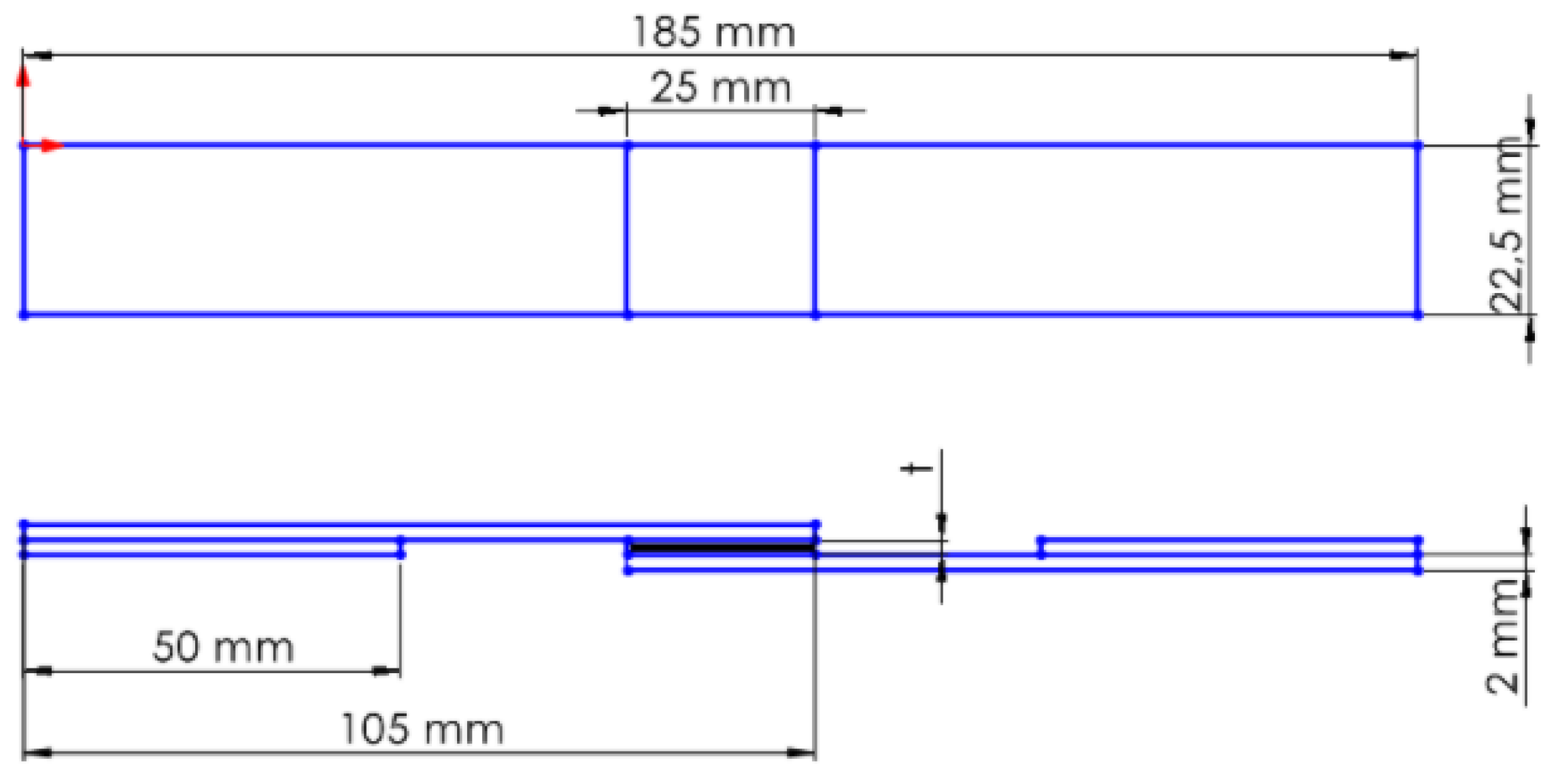
Figure 5.
Marking of GFRP and CFRP single lap configurations.
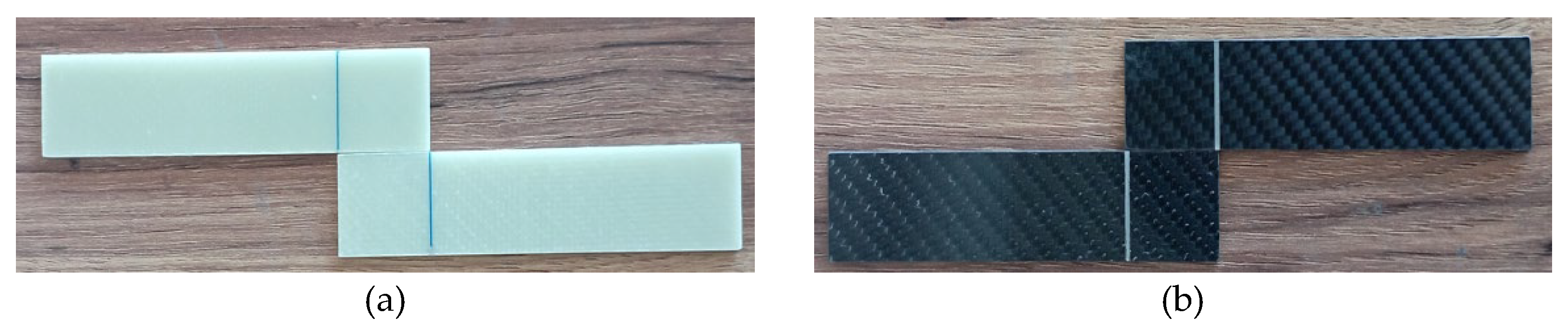
Figure 6.
Bonding Process of GFRP and CFRP Specimens Using Loctite Hysol-9466.
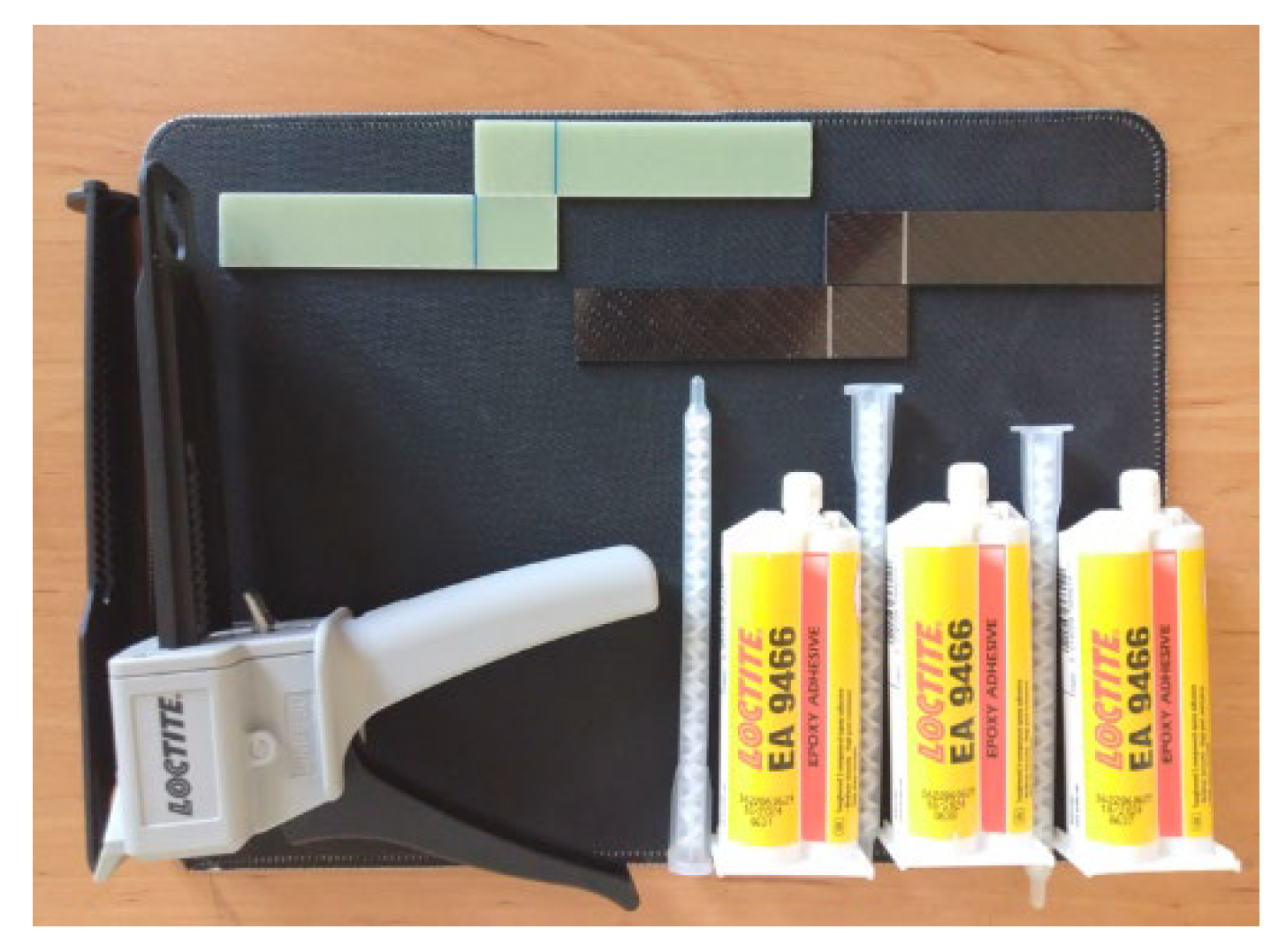
Figure 7.
Visual observation of the surface morphology of GFRP and CFRP specimens prior to the three-point bending test.
Figure 7.
Visual observation of the surface morphology of GFRP and CFRP specimens prior to the three-point bending test.
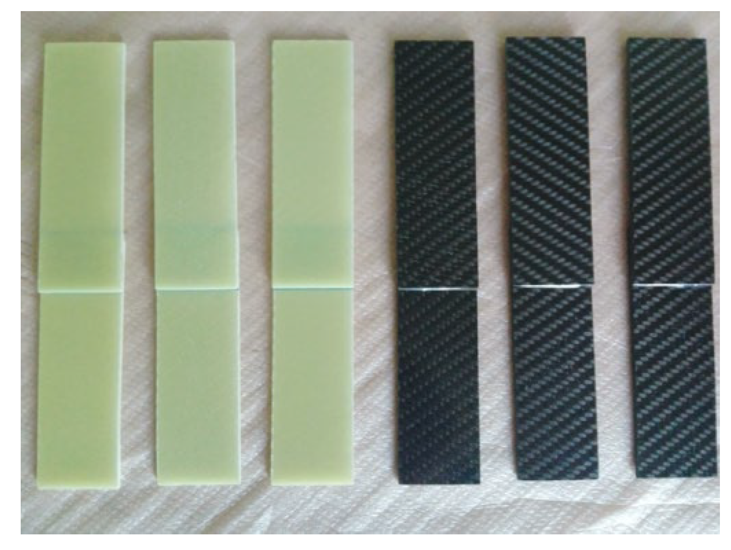
Figure 8.
Visual observation of the surface morphology of GFRP and CFRP specimens prior to the four-point bending test.
Figure 8.
Visual observation of the surface morphology of GFRP and CFRP specimens prior to the four-point bending test.
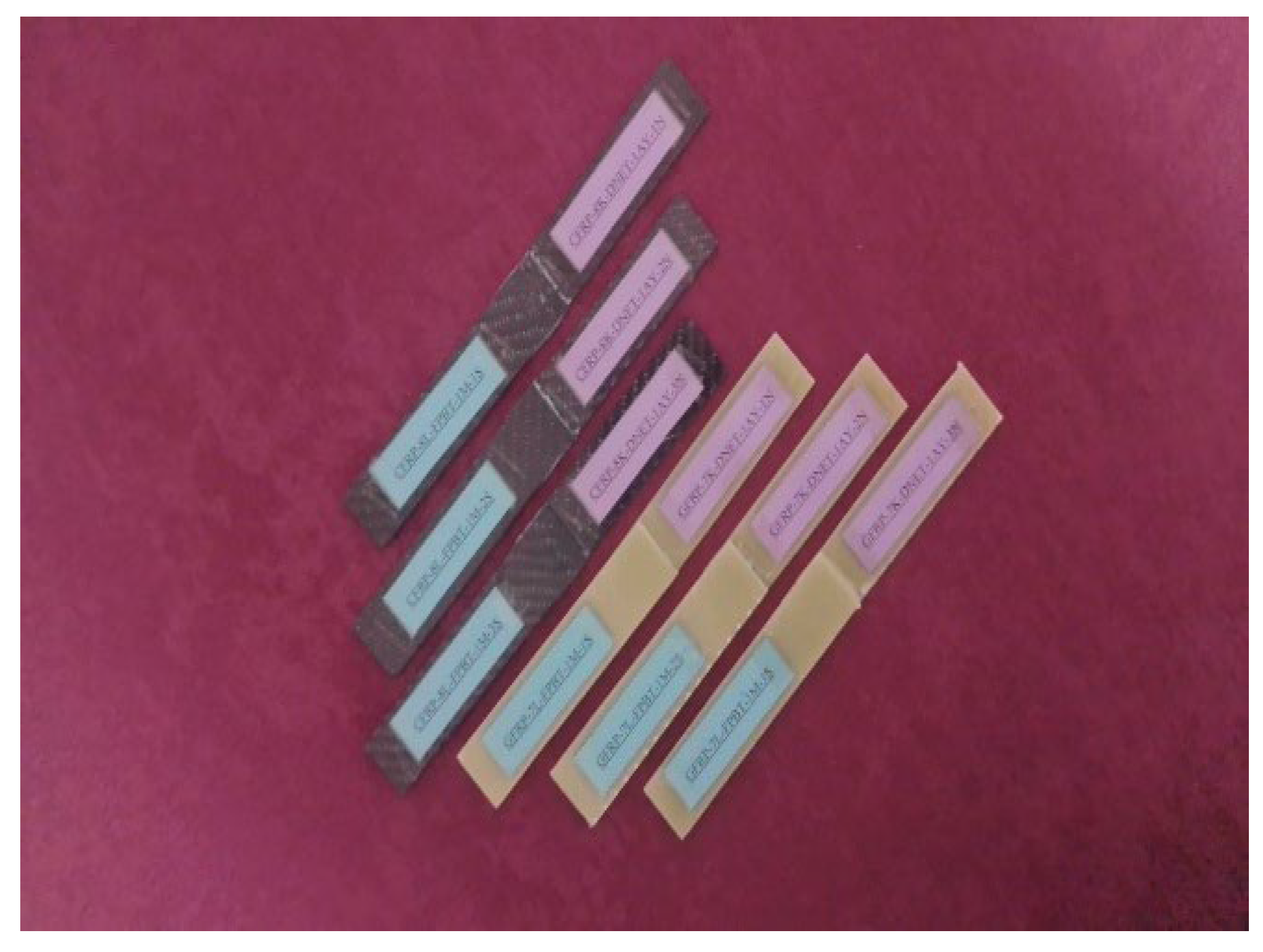
Figure 9.
GFRP (a) and CFRP (b) specimen configurations used during the three-point bending test.

Figure 10.
GFRP (a) and CFRP (b) specimen configurations used during the four-point bending test.
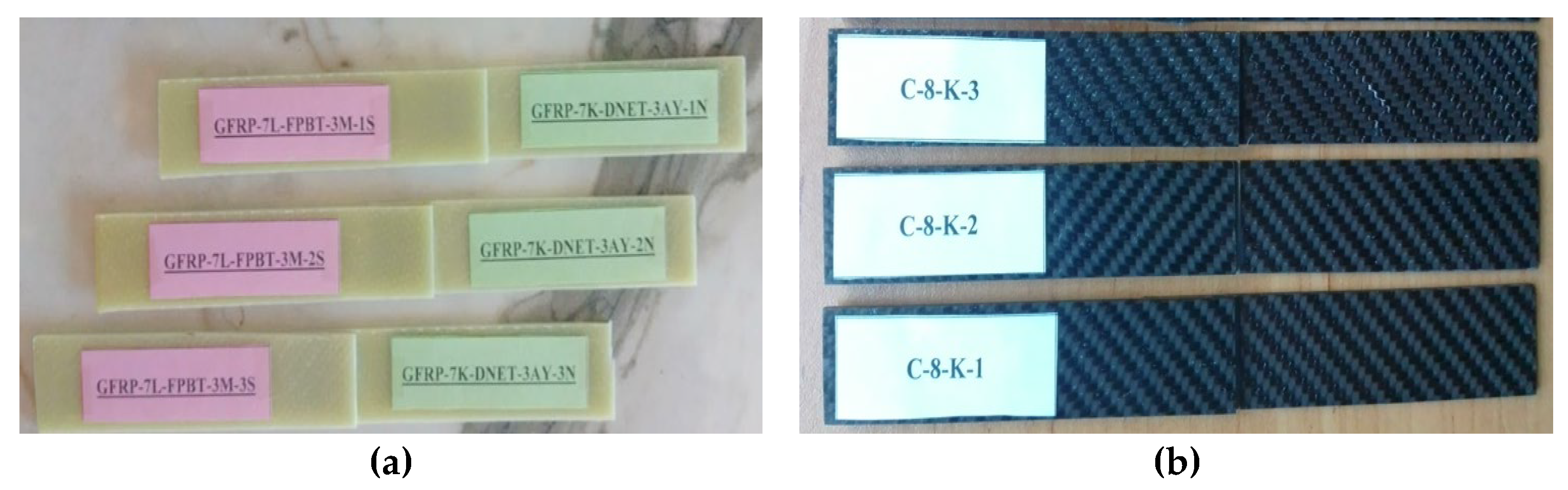
Figure 13.
Schematic view of the three point bending test conditions.
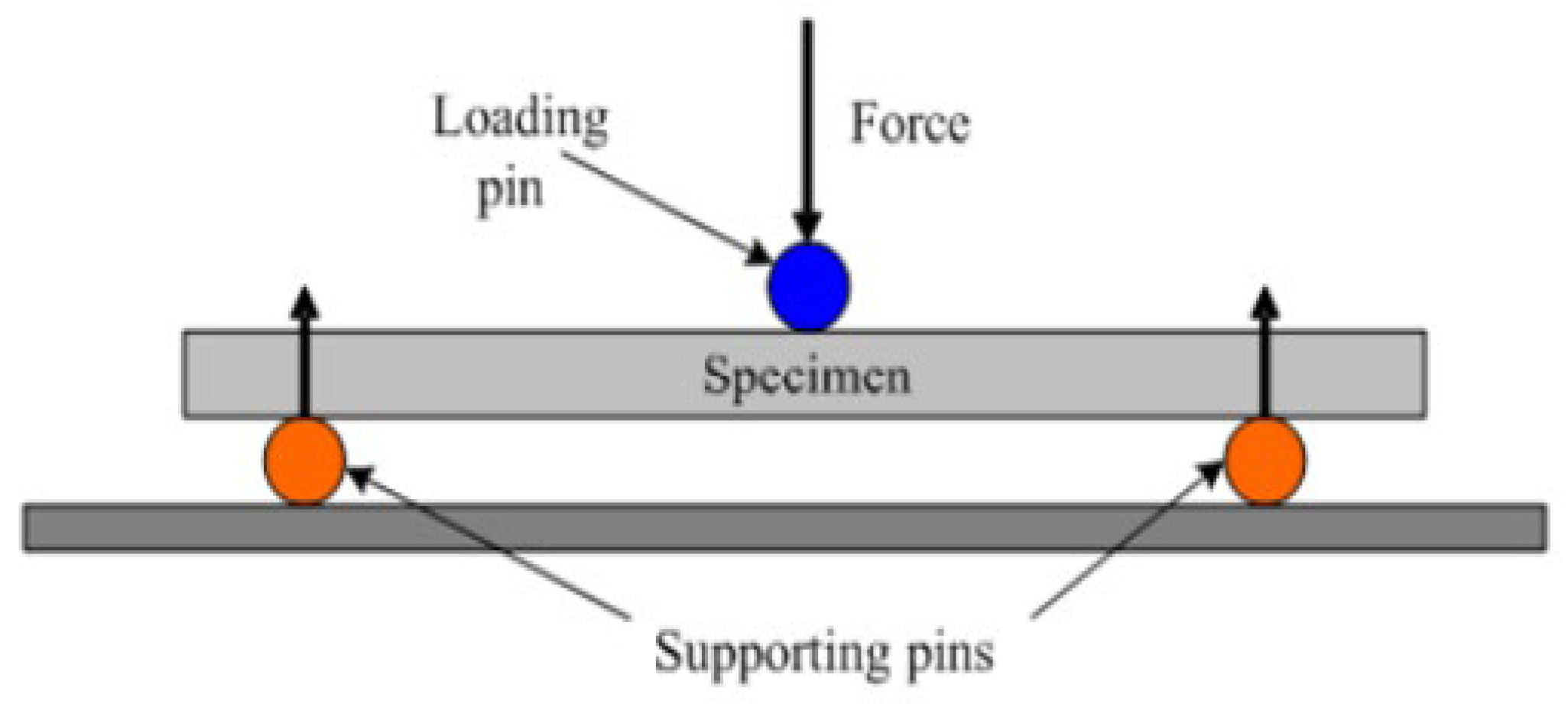
Figure 14.
Schematic view of the four point bending test conditions.
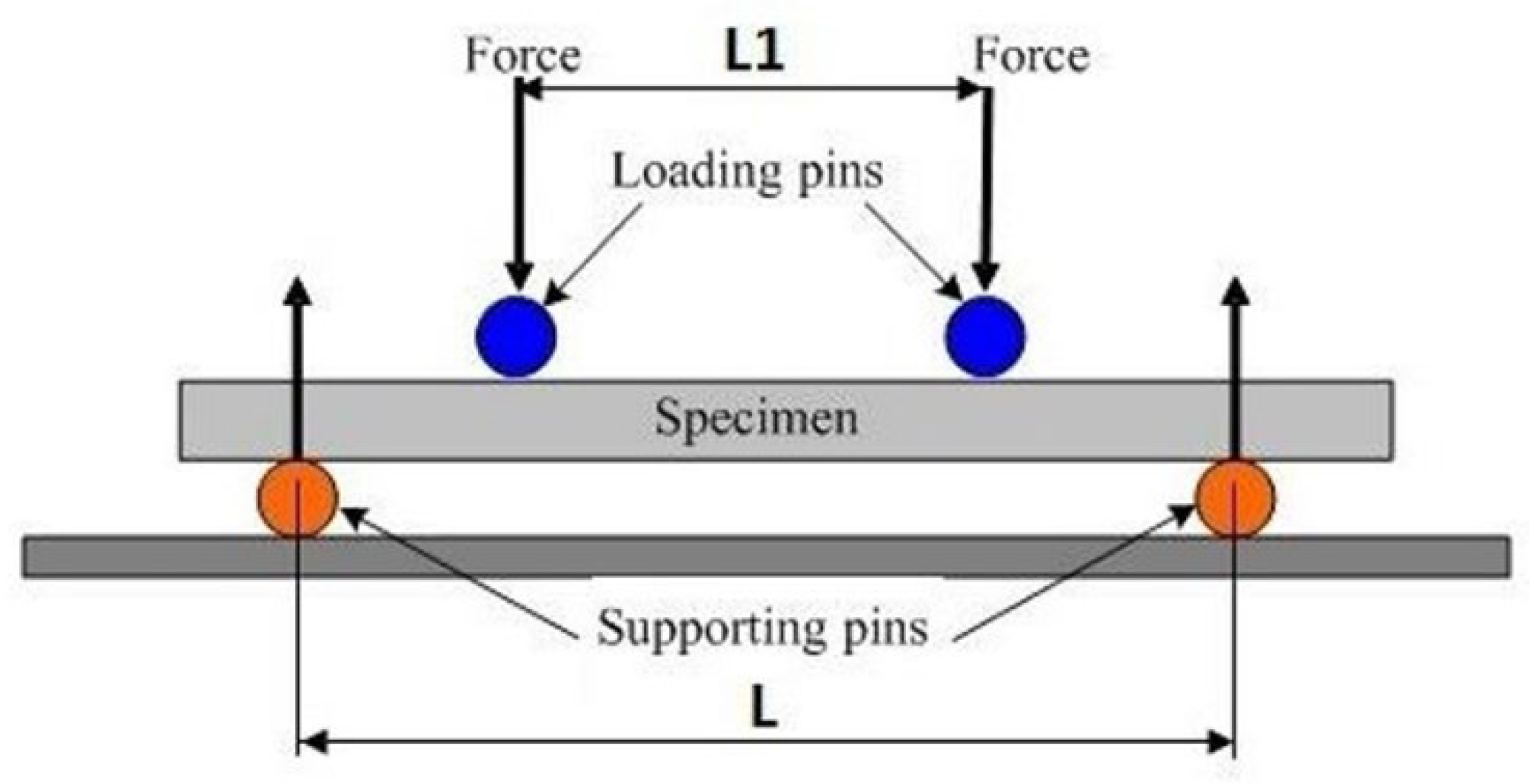
Figure 15.
Placement of the sample in the three-point bending test (a), placement of the sample in the four-point bending test(b).
Figure 15.
Placement of the sample in the three-point bending test (a), placement of the sample in the four-point bending test(b).

Figure 16.
Views of the G-7-K sample after the three-point bending test (a) and the C-8-K sample after the test (b).
Figure 16.
Views of the G-7-K sample after the three-point bending test (a) and the C-8-K sample after the test (b).
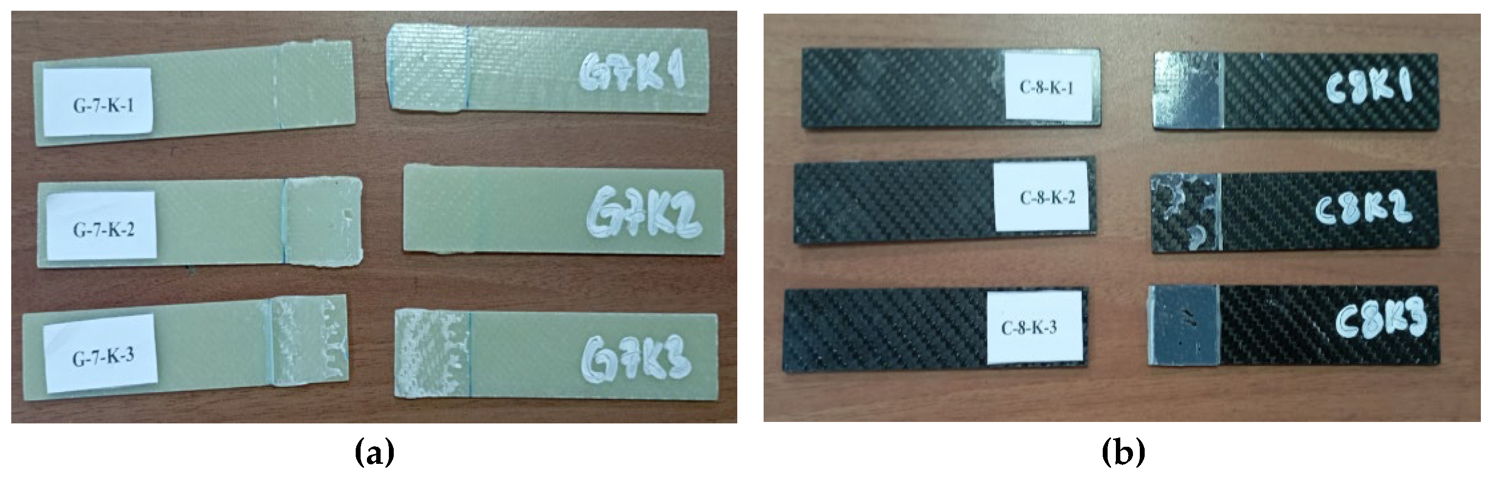
Figure 17.
Views of the G-7-1A sample after the three-point bending test (a) and the C-8-1A sample after the test (b).
Figure 17.
Views of the G-7-1A sample after the three-point bending test (a) and the C-8-1A sample after the test (b).
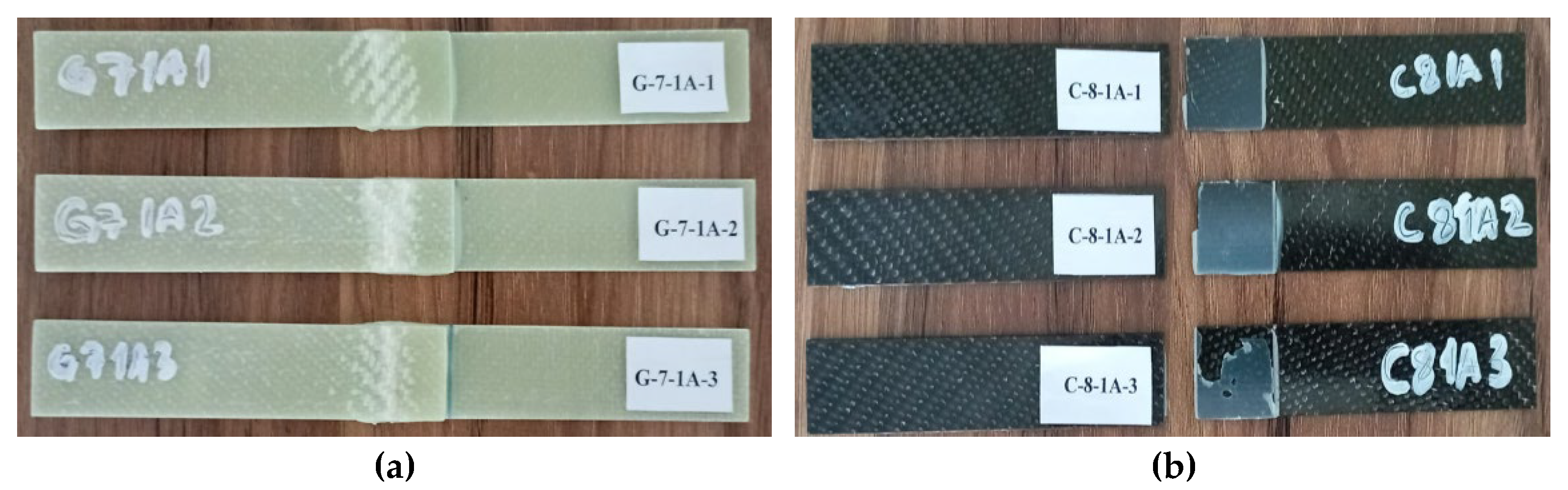
Figure 18.
Views of G-7-2A sample (a) and C-8-1A sample (b) after three-point bending test.
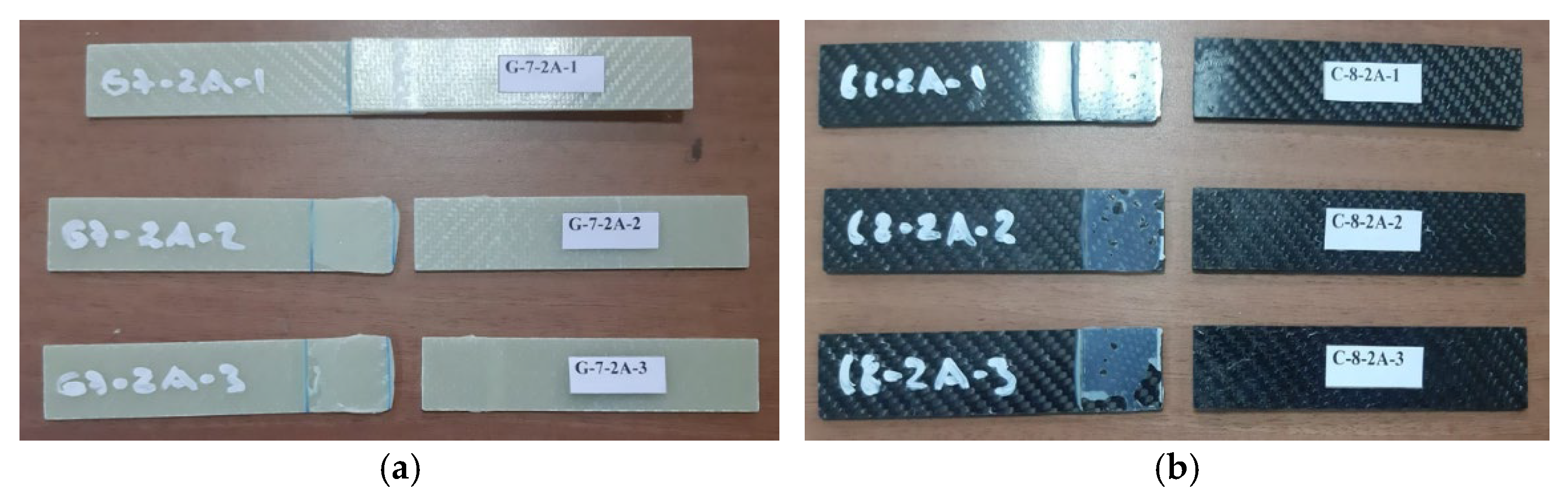
Figure 19.
Views of G-7-3A sample (a) and C-8-3A sample (b) after three-point bending test.
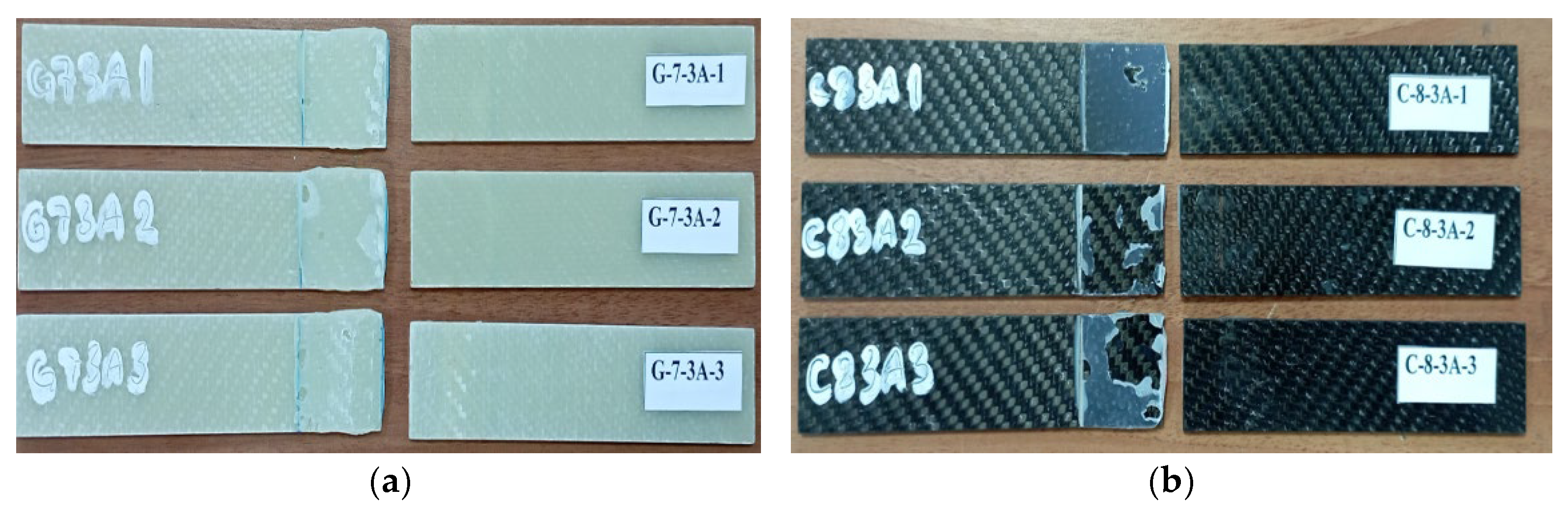
Figure 20.
Stress–strain curves of GFRP specimens exposed to seawater for different durations and stored under dry conditions.
Figure 20.
Stress–strain curves of GFRP specimens exposed to seawater for different durations and stored under dry conditions.
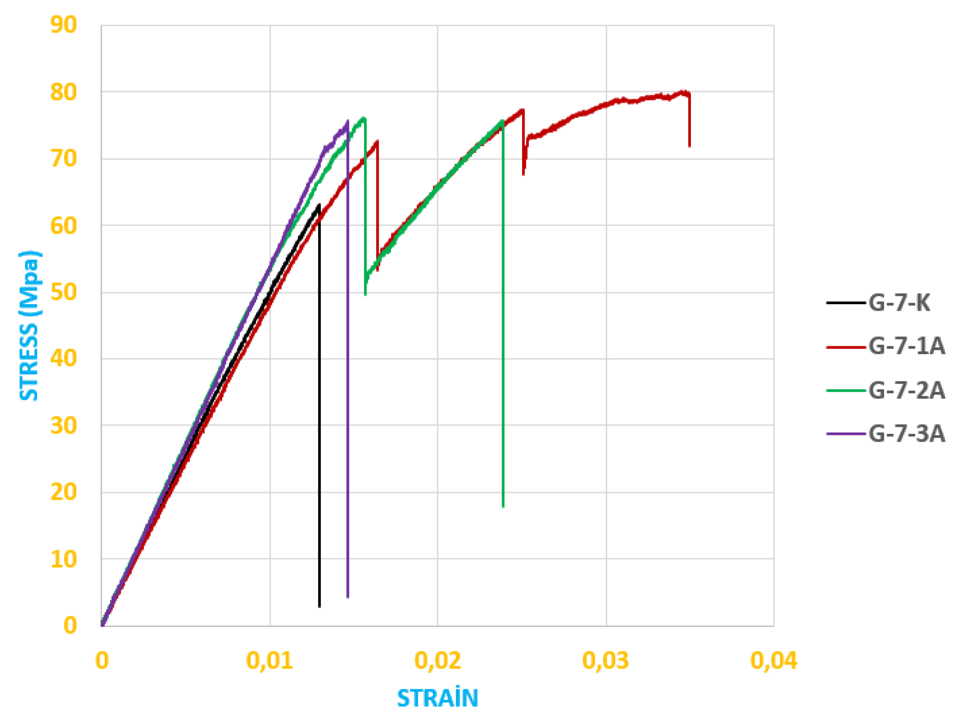
Figure 21.
Stress–strain curves of CFRP specimens exposed to seawater for different durations and stored under dry conditions.
Figure 21.
Stress–strain curves of CFRP specimens exposed to seawater for different durations and stored under dry conditions.
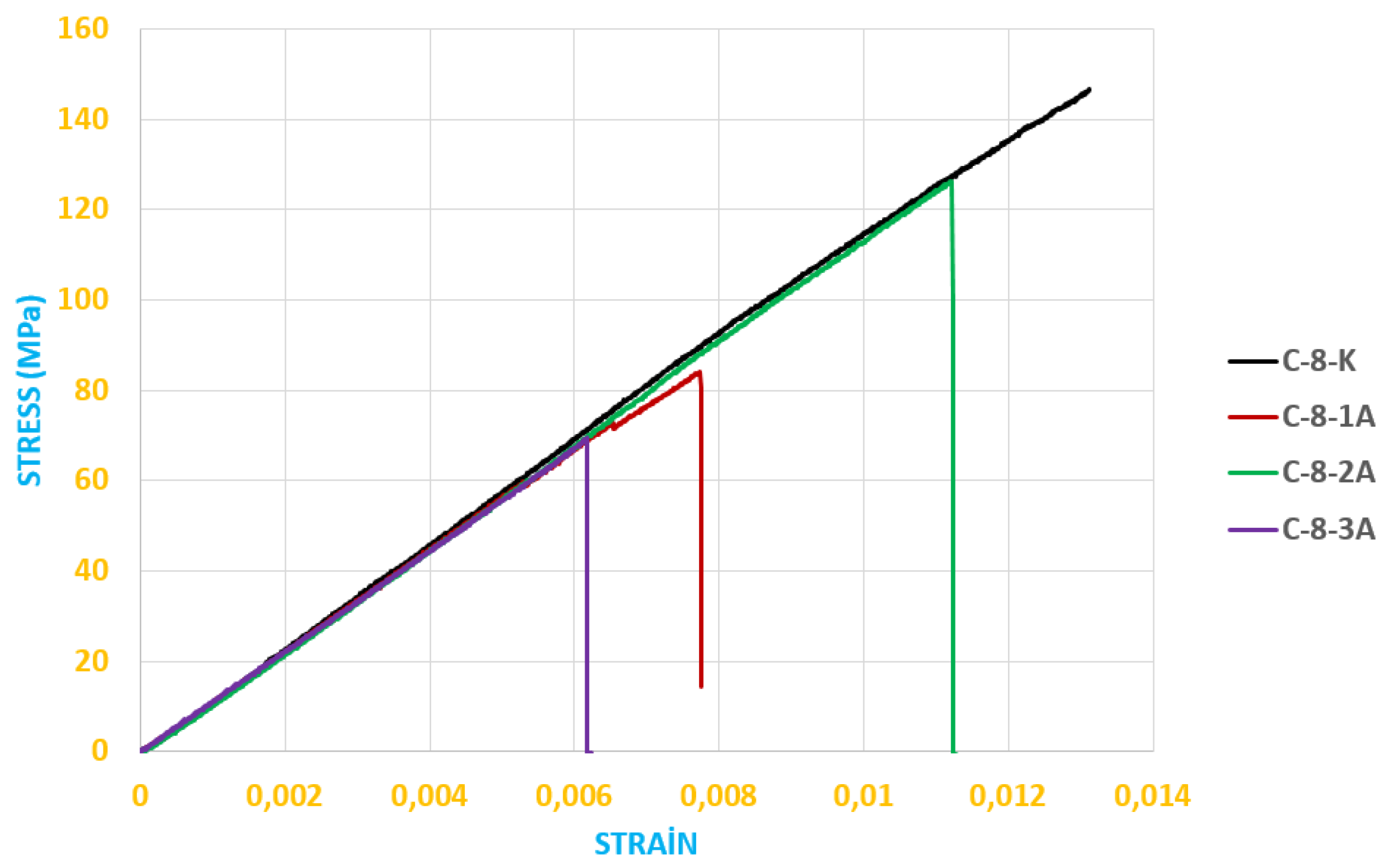
Figure 22.
Views of the GFRP-7L-FPBT-DE-1S specimen (a) and CFRP-8L-FPBT-DE-1S specimen (b) after the four-point bending test.
Figure 22.
Views of the GFRP-7L-FPBT-DE-1S specimen (a) and CFRP-8L-FPBT-DE-1S specimen (b) after the four-point bending test.
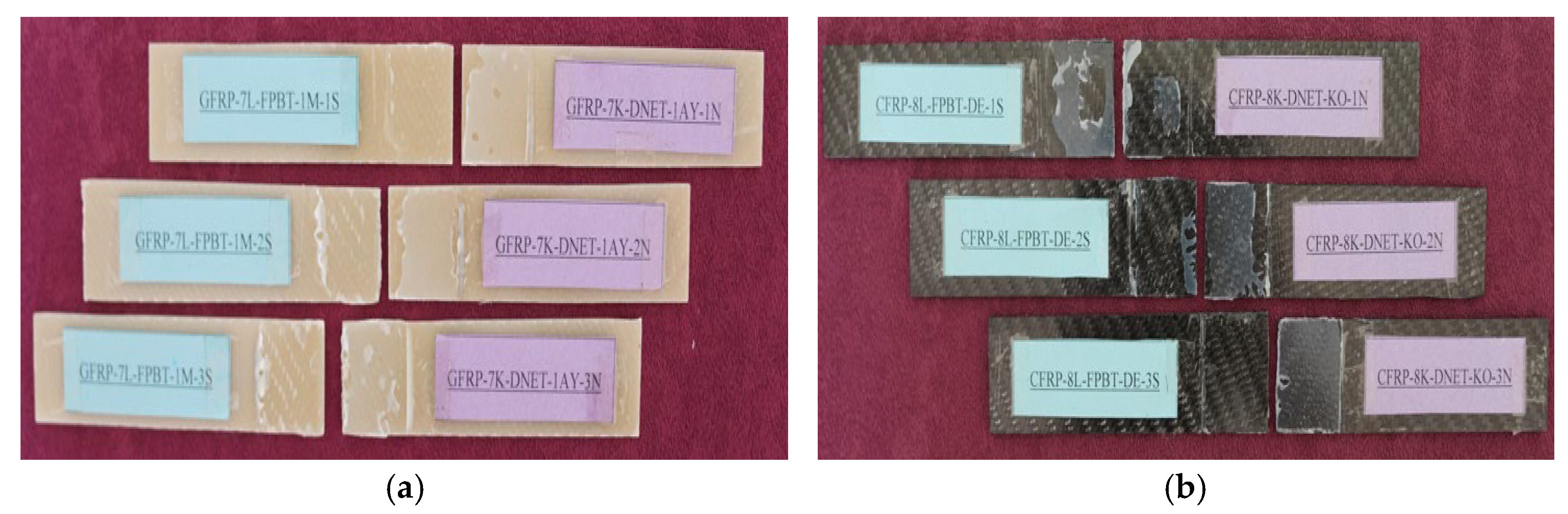
Figure 23.
GFRP-7L-FPBT-1M numunesi (a) ve CFRP-8L-FPBT-1M numunesinin (b) dört nokta eğme test sonrası görünümleri.
Figure 23.
GFRP-7L-FPBT-1M numunesi (a) ve CFRP-8L-FPBT-1M numunesinin (b) dört nokta eğme test sonrası görünümleri.
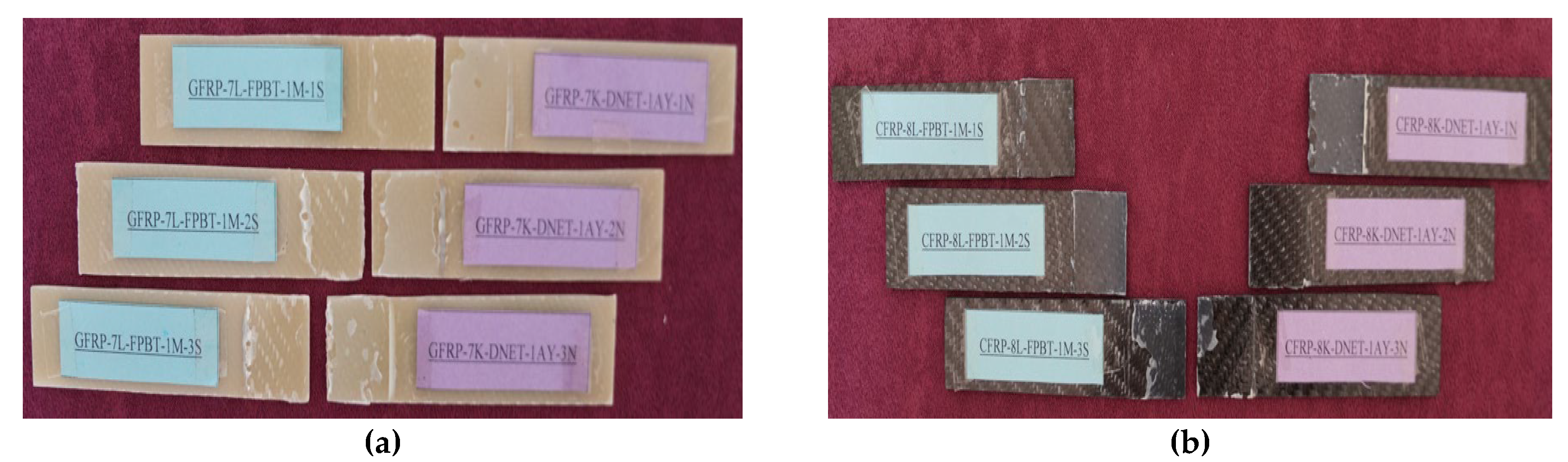
Figure 24.
Views of the GFRP-7L-FPBT-2M specimen (a) and CFRP-8L-FPBT-2M specimen (b) after the four-point bending test.
Figure 24.
Views of the GFRP-7L-FPBT-2M specimen (a) and CFRP-8L-FPBT-2M specimen (b) after the four-point bending test.
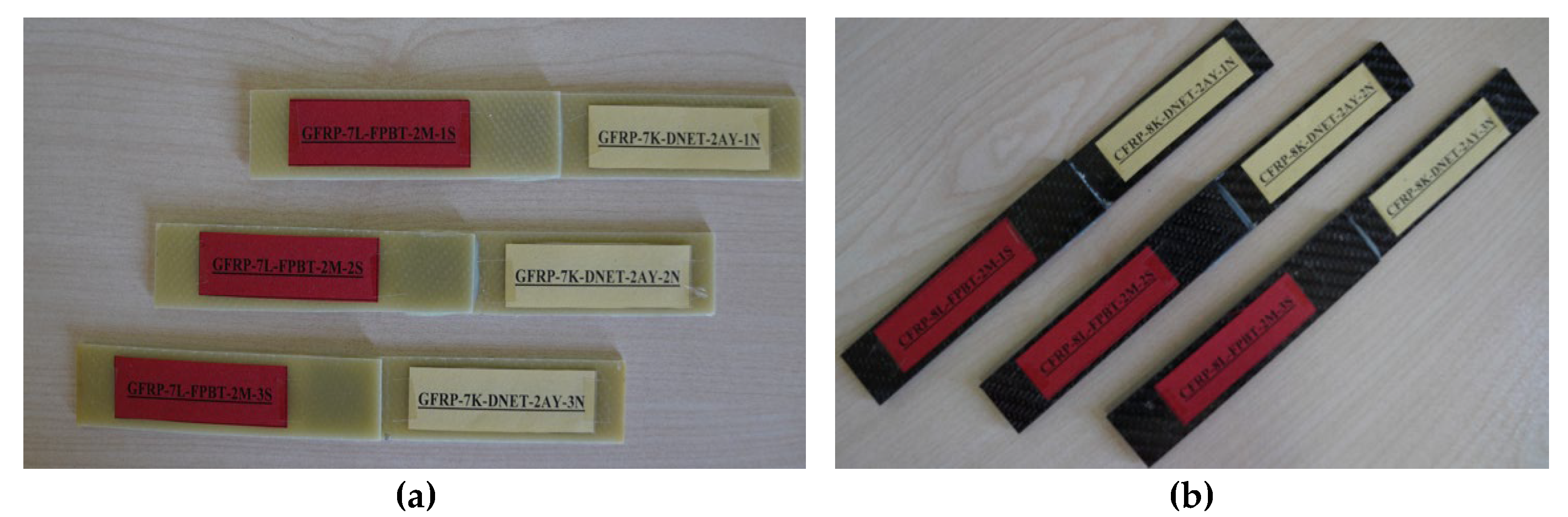
Figure 25.
Views of GFRP-7L-FPBT-3M specimen (a) and CFRP-8L-FPBT-3M specimen (b) after four-point bending test.
Figure 25.
Views of GFRP-7L-FPBT-3M specimen (a) and CFRP-8L-FPBT-3M specimen (b) after four-point bending test.
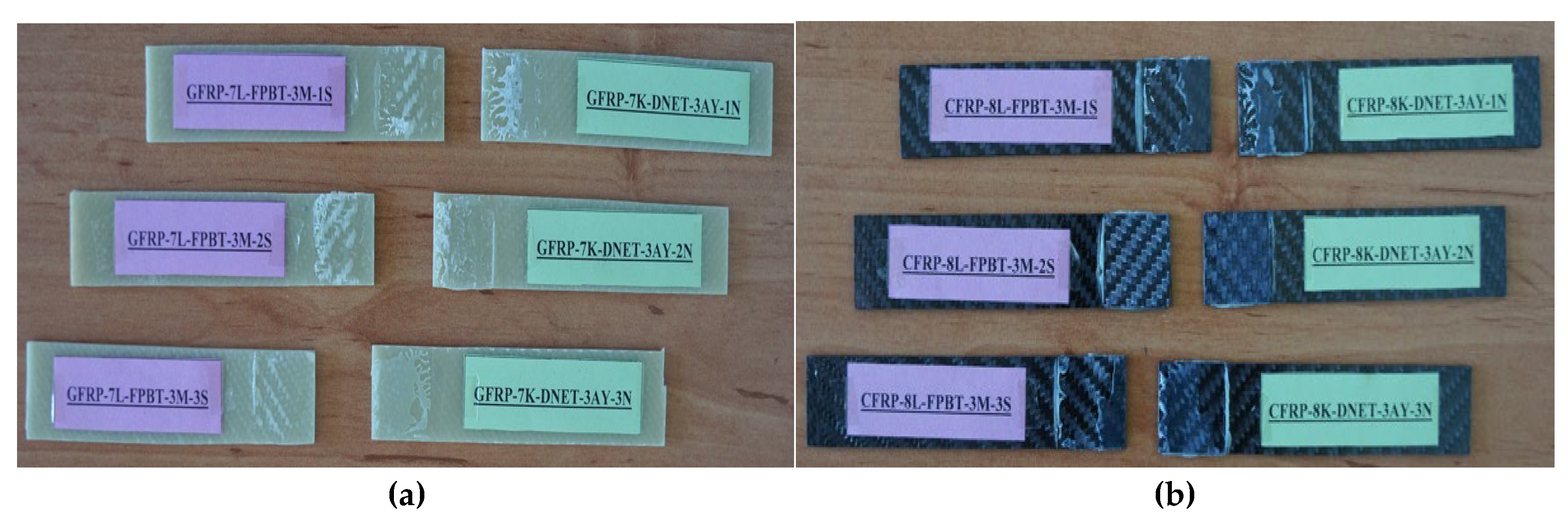
Figure 26.
Stress–strain curves of GFRP specimens exposed to seawater for different durations and stored under dry conditions.
Figure 26.
Stress–strain curves of GFRP specimens exposed to seawater for different durations and stored under dry conditions.
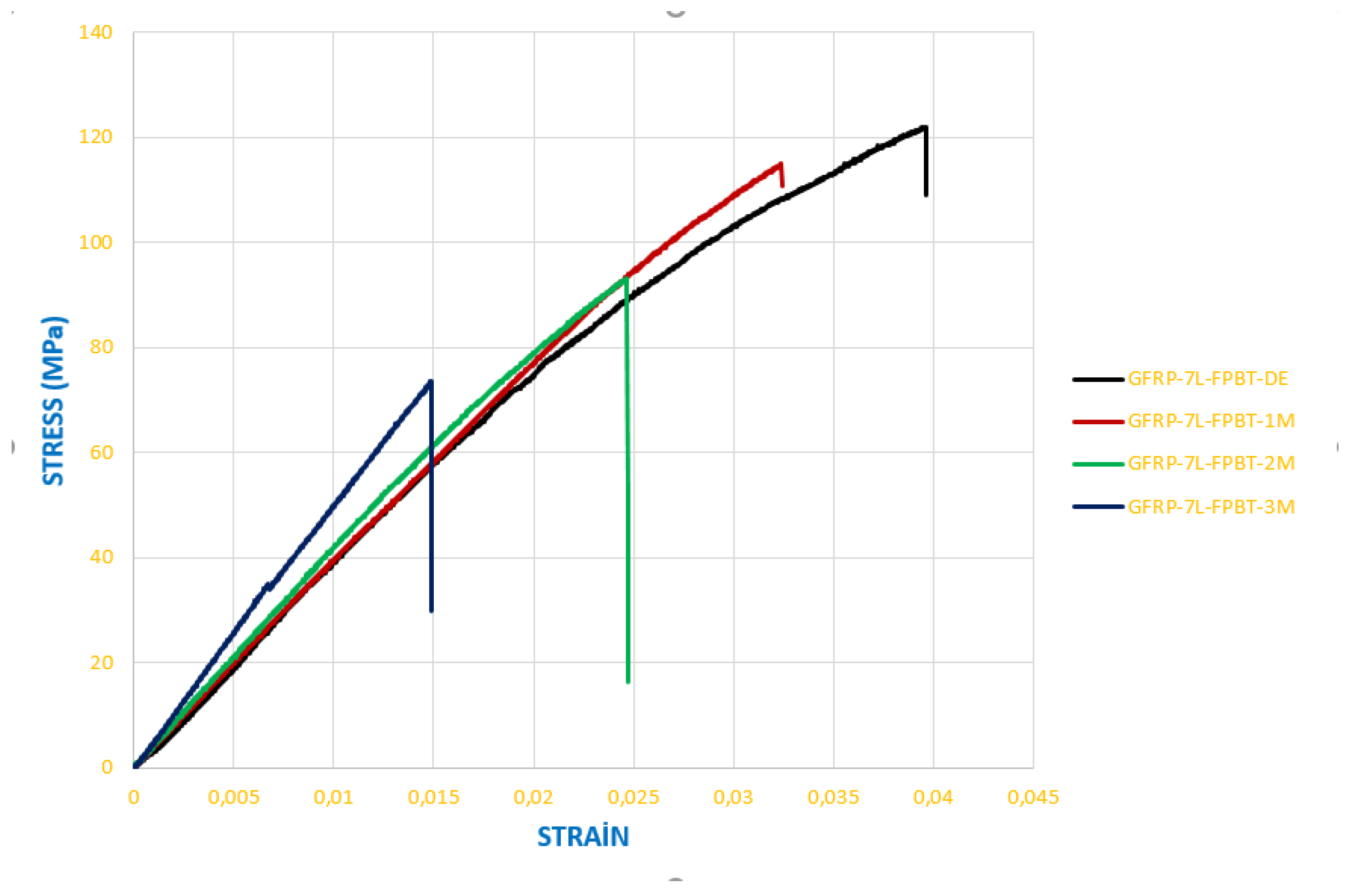
Figure 27.
Stress–strain curves of CFRP specimens exposed to seawater for different durations and stored under dry conditions.
Figure 27.
Stress–strain curves of CFRP specimens exposed to seawater for different durations and stored under dry conditions.
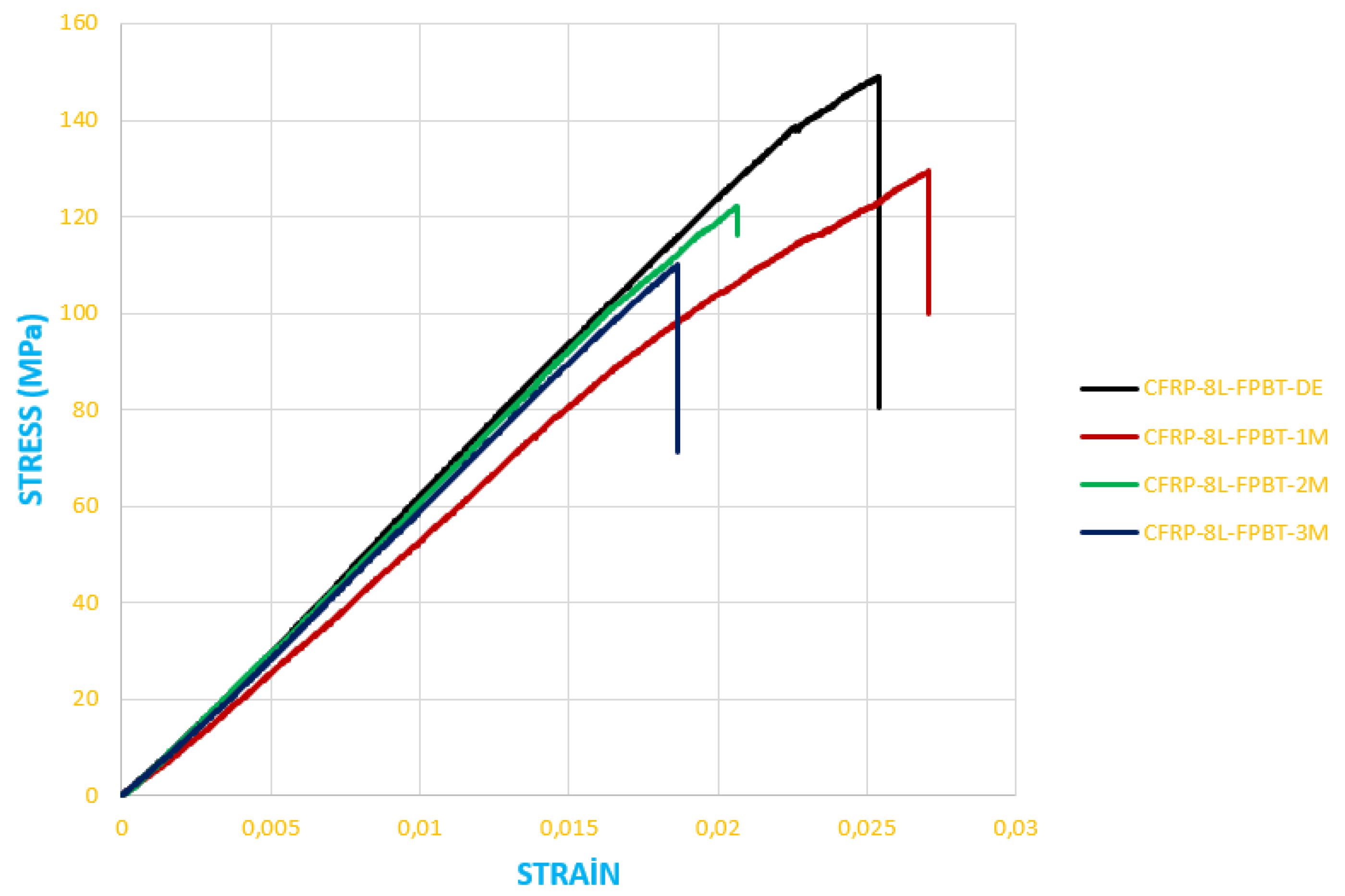
Figure 28.
Reference (dry condition) (a), 1 month (b), 2 months (b), 3 months (c) seawater-exposed GFRP specimens.
Figure 28.
Reference (dry condition) (a), 1 month (b), 2 months (b), 3 months (c) seawater-exposed GFRP specimens.
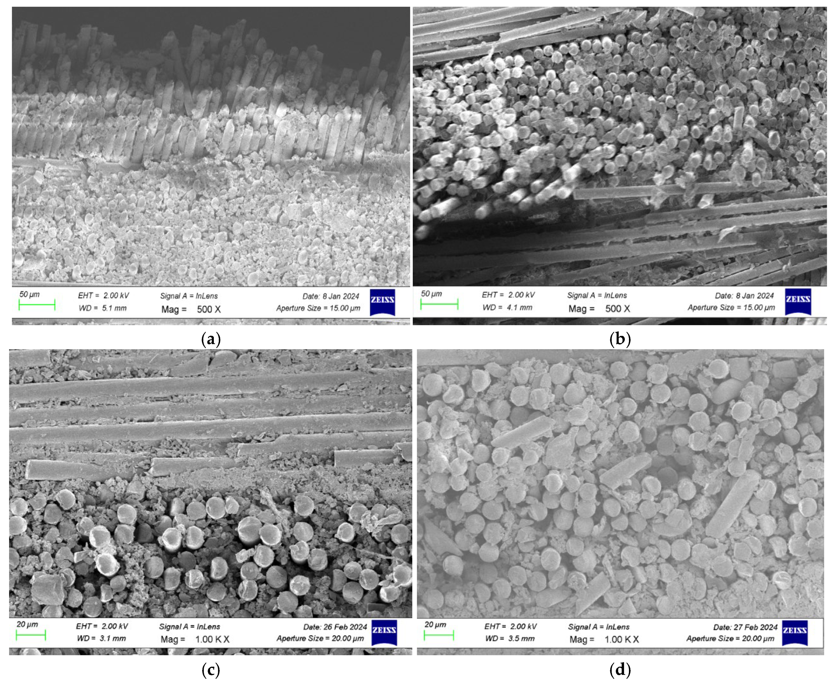
Figure 29.
Reference (dry condition) (a), 1 month (b), 2 months (b), 3 months (c) seawater-exposed CFRP specimens.
Figure 29.
Reference (dry condition) (a), 1 month (b), 2 months (b), 3 months (c) seawater-exposed CFRP specimens.
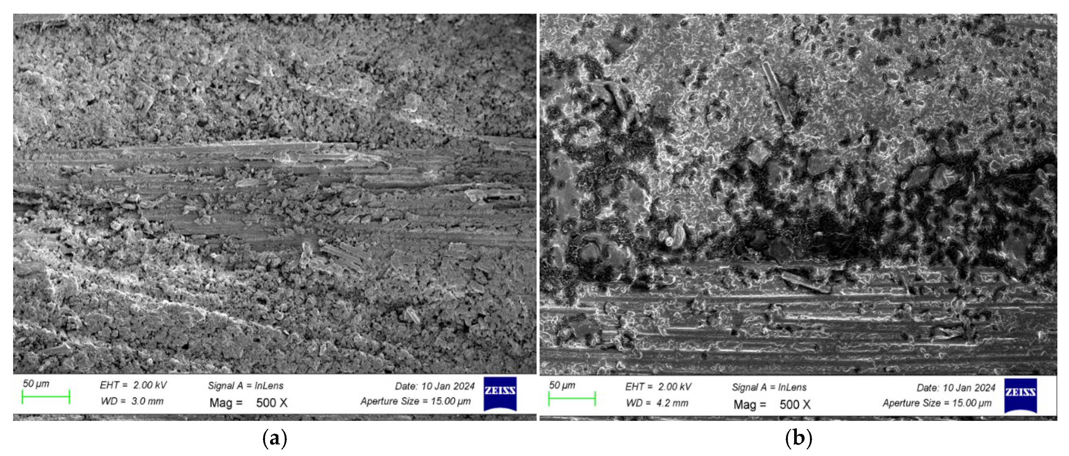
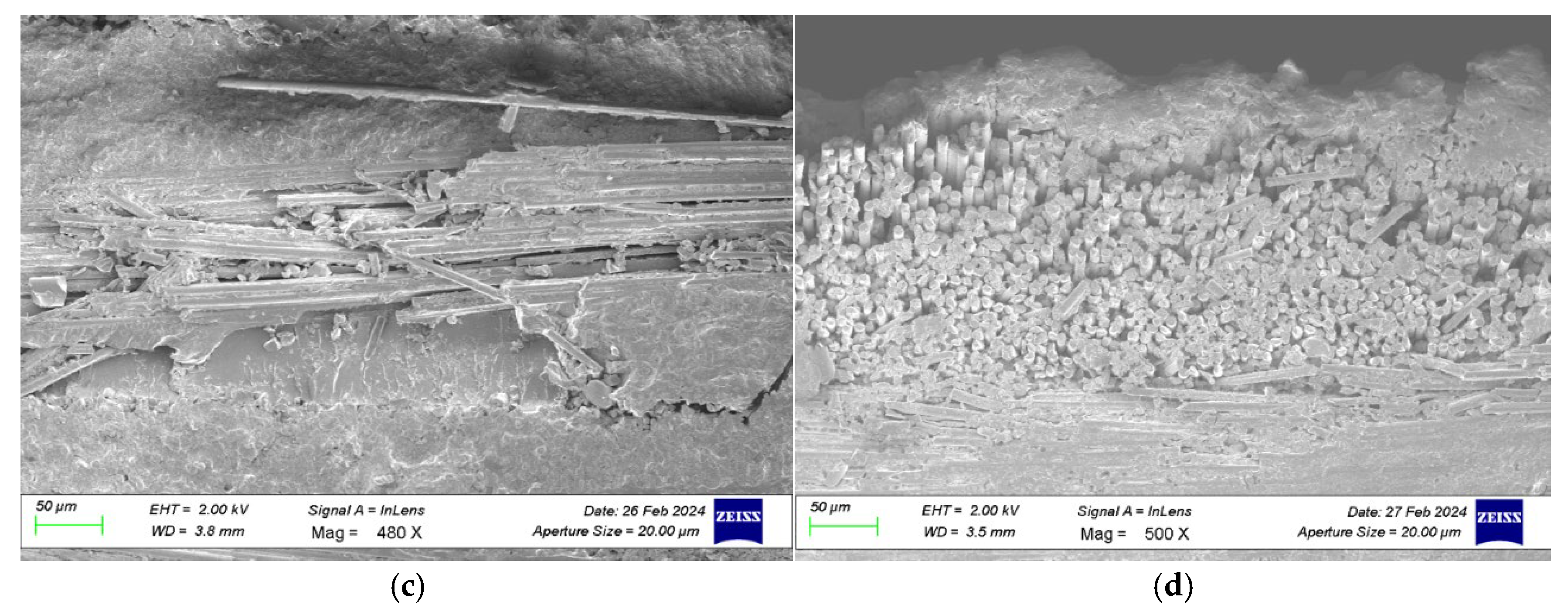
Figure 30.
Reference (dry condition) (a), 1 month (b), 2 months (c), 3 months (d) seawater-exposed GFRP specimens.
Figure 30.
Reference (dry condition) (a), 1 month (b), 2 months (c), 3 months (d) seawater-exposed GFRP specimens.
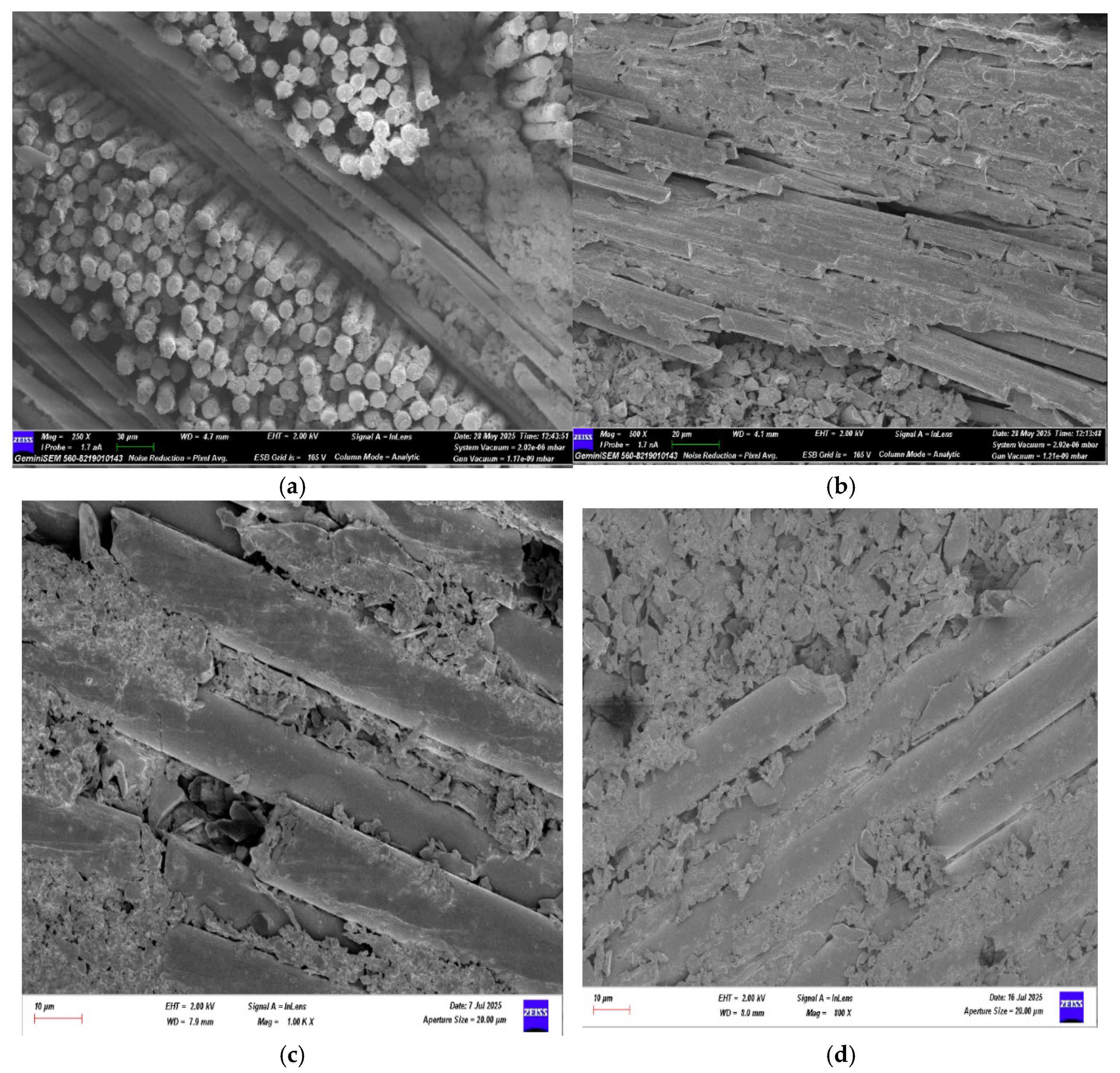
Figure 31.
Reference (dry condition) (a), 1 month (b), 2 months (c), 3 months (d) seawater-exposed CFRP specimens.
Figure 31.
Reference (dry condition) (a), 1 month (b), 2 months (c), 3 months (d) seawater-exposed CFRP specimens.
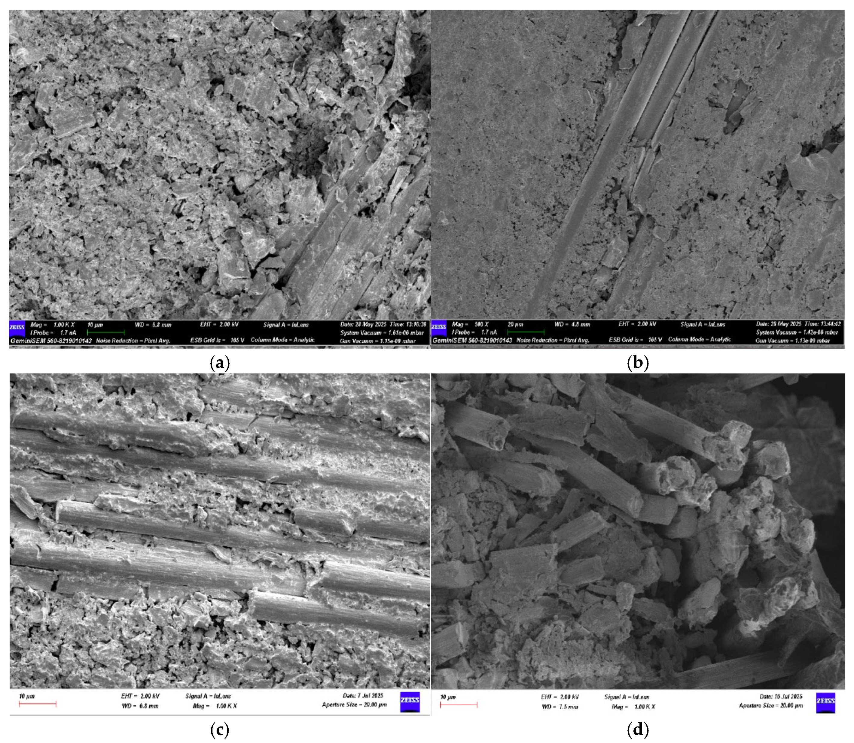
Table 1.
Coding System for GFRP and CFRP Specimens for Three and Four-Point Bending Tests.
| Code | Test Type | Description |
|---|---|---|
| G-7-K-1 | Three-Point Bending | Glass fiber (G), 7 layers, tested in dry condition(K), specimen 1 |
| G-7-1A-1 | Three-Point Bending | Glass fiber(G), 7 layers, conditioned in seawater for 1 month (1A), specimen 1 |
| C-8-K-1 | Three-Point Bending | Carbon fiber (C), 8 layers, tested in dry condition(K), specimen 1 |
| GFRP-7L-FPBT-DE-1S | Four-Point Bending | Glass fiber (GFRP), 7 layers (7L), four-point bending test (FPBT), dry condition (DE), specimen 1(1S) |
| GFRP-7L-FPBT-2M-1S | Four-Point Bending | Glass fiber (GFRP), 7 layers (7L), four-point bending test (FPBT), 2 months in seawater (2M), specimen 1 (1S) |
| CFRP-8L-FPBT-DE-1S | Four-Point Bending | Carbon fiber (CFRP), 8 layers (8L), four-point bending test (FPBT), dry condition (DE), specimen 1(1S) |
Table 2.
Bending Stress and Strain Values of GFRP Specimens.
| Specimen Code | Exposure Time | Flexural Stress (MPa) | Strain (ε) | Description/Status |
|---|---|---|---|---|
| G-7-K | Dry (Reference) | 63.0726 | 0.0129 | Maximum stress value |
|
G-7-1A |
1 month |
72.2704 | 0.0163 | Initial stress |
| 54.4886 | 0.0113 | Minimum stress | ||
| 80.0818 | 0.0347 | Maximum stress | ||
|
G-7-2A |
2 months | 75.8136 | 0.0156 | Initial maximum stress |
| 50.8163 | 0.0094 | Stress reduction | ||
| 75.6766 | 0.0154 | Stress increase | ||
| G-7-3A | 3 months | 75.6723 | 0.0146 | Initial maximum stress |
Table 3.
Bending Stress and Strain Values of CFRP Specimens.
| Specimen Code | Exposure Time | Flexural Stress (MPa) | Strain (ε) | Description/Status |
|---|---|---|---|---|
| C-8-K | Dry (Reference) | 146.5976 | 0.0131 | Maximum bending stress |
|
C-8-1A |
1 month |
72.4395 | 0.0065 | Initial stress |
| 83.6555 | 0.0077 | Maximum stress | ||
| C-8-2A | 2 months | 126.2889 | 0.0112 | Initial and maximum stress |
| C-8-3A | 3 months | 69.1586 | 0.0061 | Bending stress |
Table 4.
Young’s Modulus (E) of GFRP and CFRP specimens.
| Sample Code | Material Type | Elastic Modulus (E) (GPa) | Change Compared to Reference (%) |
|---|---|---|---|
| GFRP-7L-FPBT-DE | GFRP | 3.840 | Dry environment (reference) |
| GFRP-7L-FPBT-1M | GFRP | 3.856 | % 3.15 |
| GFRP-7L-FPBT-2M | GFRP | 3.843 | % 6.42 |
| GFRP-7L-FPBT-3M | GFRP | 5.213 | % 9.45 |
| CFRP-8L-FPBT-DE | CFRP | 6.270 | Dry environment (reference) |
| CFRP-8L-FPBT-1M | CFRP | 5.380 | % 1.29 |
| CFRP-8L-FPBT-2M | CFRP | 6.169 | % 2.62 |
| CFRP-8L-FPBT-3M | CFRP | 6.036 | % 3.48 |
Table 5.
Bending Stress and Strain Values of GFRP Specimens.
| Specimen Code | Exposure Time | Flexural Stress (MPa) | Strain (ε) | Description/Status |
|---|---|---|---|---|
| GFRP-7L-FPBT-DE | Dry (Reference) | 121.6930 | 0.0395 | Maximum bending stress |
| GFRP-7L-FPBT-1M | 1 month | 114.9519 | 0.0323 | Initial stress |
| GFRP-7L-FPBT-2M | 2 months | 92.6155 | 0.0244 | Highest stress |
| GFRP-7L-FPBT-3M | 3 months | 72.7945 | 0.0146 | Lowest stress |
Table 6.
Bending Stress and Strain Values of CFRP Samples.
| Specimen Code | Exposure Time | Flexural Stress (MPa) | Strain (ε) | Description/Status |
|---|---|---|---|---|
| CFRP-8L-FPBT-DE | Dry (Reference) | 148.5722 | 0.0254 | Maximum bending stress |
| CFRP-8L-FPBT-1M | 1 month | 12.2385 | 0.0270 | Slight increase in flexibility at the beginning (matrix softening) |
| CFRP-8L-FPBT-2M | 2 months | 121.9446 | 0.0206 | Tendency of stress reduction |
| CFRP-8L-FPBT-3M | 3 months | 109.5578 | 0.0185 | Noticeable mechanical degradation |
Table 7.
Young’s Modulus (E) of GFRP and CFRP specimens.
| Sample Code | Material Type | Elastic Modulus (E) (GPa) | Change Compared to Reference (%) |
|---|---|---|---|
| G-7-K | GFRP | 5.39 | Dry environment (reference) |
| G-7-1A | GFRP | 5.07 | % 5.94 |
| G-7-2A | GFRP | 4.91 | % 8.90 |
| G-7-3A | GFRP | 4.69 | % 12.98 |
| C-8-K | CFRP | 11.50 | Dry environment (reference) |
| C-8-1A | CFRP | 11.36 | % 1.28 |
| C-8-2A | CFRP | 11.11 | % 3.39 |
| C-8-3A | CFRP | 11.07 | % 3.74 |
Table 8.
Comparison of the Results of Three-Point Bending and Four-Point Bending Tests.
| Condition | Three-Point Bending Results | Four-Point Bending Results |
|---|---|---|
| Dry Environment (Reference) |
|
|
| Samples Soaked in Seawater for 1 Month |
|
|
| Samples Soaked in Seawater for 2 Months |
|
|
| Samples Soaked in Seawater for 3 Months |
|
|
Table 9.
Performance Analysis of Three-Point and Four-Point Bending Test Results.
| Observation | Three-Point Bending | Four-Point Bending |
|---|---|---|
| Damage Initiation | Typically initiates along the bond line, especially at the edge regions. | Initiates at the bond line and propagates toward the surfaces. |
| Type of Damage | Over time, adhesive and cohesive failures are observed simultaneously. | Mixed-mode failure (adhesive + cohesive) is dominant. |
| Effect of Seawater | Rapid degradation is seen in GFRP specimens, while the effect is limited in CFRP specimens. | In GFRP specimens, chemical and physical degradation occurs, whereas in CFRP specimens, low water absorption helps preserve strength. |
| Fracture Behavior | GFRP specimens exhibit ductile–mixed behavior; CFRP specimens show brittle behavior. | GFRP: delamination observed; CFRP: sudden but controlled fracture observed. |
| Preservation of Structural Strength | CFRP > GFRP | CFRP > GFRP |
| Result of Long-Term Exposure | Adhesive strength decreases significantly in GFRP specimens. |
CFRP specimens maintain structural integrity for a longer period. |
Disclaimer/Publisher’s Note: The statements, opinions and data contained in all publications are solely those of the individual author(s) and contributor(s) and not of MDPI and/or the editor(s). MDPI and/or the editor(s) disclaim responsibility for any injury to people or property resulting from any ideas, methods, instructions or products referred to in the content. |
© 2025 by the authors. Licensee MDPI, Basel, Switzerland. This article is an open access article distributed under the terms and conditions of the Creative Commons Attribution (CC BY) license (https://creativecommons.org/licenses/by/4.0/).
Copyright: This open access article is published under a Creative Commons CC BY 4.0 license, which permit the free download, distribution, and reuse, provided that the author and preprint are cited in any reuse.


