
Submitted:
09 November 2025
Posted:
10 November 2025
You are already at the latest version
Abstract
A 1.13 mm long fatigue crack in a 09G2S steel plate was completely healed using pulsed current treatment. The following pulsed current parameters were used: number of pulses – 6, pulse duration – 10-4 s, capacitor voltage increased from pulse to pulse in the range of 200÷250 V, maximum current density – 103÷1.25×10³ A/mm2. To under-stand the healing mechanism, microstructural studies were performed using a scan-ning electron microscope near the healed crack and microhardness measurements in this area. The area near the healed crack can be roughly divided into three zones: the melting zone (MZ), the heat-affected zone (HAZ), and the base metal zone (BMZ). In the MZ, as a result of strong heating due to the current pulse, melting and subsequent quenching due to rapid cooling occurred, forming a lamellar martensite structure characterized by increased microhardness. In the HAZ, as a result of Joule heat release in an area previously unevenly deformed during fatigue testing, primary recrystalliza-tion occurred, forming a heterogeneous structure with ferrite grains of varying sizes and orientations. Moreover, the grain size in the HAZ was significantly smaller than in the BMZ. It is also worth noting that after healing, defects associated with the dis-placement of impurities by the crystallization front toward the crack were detected in the MZ.
Keywords:
electric pulse treatment
; fatigue crack
; crack healing
; melting zone
; heat-affected zone
; microstructure
; lamellar martensite
; microhardness
1. Introduction
Systematic investigation of the effect of high-density, pulsed electric current on the structure and properties of metallic materials has begun since the discovery of the electroplasticity effect by Troitsky in 1969 [1]. Shortly after the pioneering works on electroplasticity [2,3] it became clear that the pulsed current can be used to solve various problems in materials science [4] including strengthening by grain refinement [5], increasing plasticity [6], corrosion resistance [7,8], ductility [9,10], crack healing [11] and many others. A wide spectrum of such technologies is now called the electric pulse treatment (EPT) of metals and alloys [8,12,13].
The problem of crack formation and propagation in metallic materials is a critical one in materials science, as premature failure of components and structures due to fatigue crack growth leads to significant economic losses. Therefore, extensive research is underway into methods for preventing and healing cracks in metals. EPT is one of the actively developing approach to crack healing. This technology has progressed from fundamental research to laboratory demonstrations and is currently approaching industrial implementation. In the work by Yu et al. [11] it has been demonstrated that multiple electric pulses can result in complete healing of a crack in SUS304 stainless steel via rapid melting and solidification within the affected zone, resulting in fine recrystallized structures. The crack was introduced in the sample using the method by Zhou et al [14], namely, by drilling a hole and pressing the sample until the closure of the hole. Hosoi et al. [15,16] using the high-density electropulsing have achieved up to 89% closure of fatigue cracks by surface-activated pre-coating.
In many cases, crack healing under EPT is achieved by local melting of the metal around crack tip due to the concentration of the current in this area [17,18,19,20]. However, the solid-state diffusion bonding of the crack edges can be a result of the synergetic effect of a high-temperature near the crack tip, a compressive stress induced by temperature gradients, and an electromagnetic force acting in Mode I, all arising from the flow of the high-density electric current [21]. For non-metallic materials the methods of self-healing of cracks are been developed [22,23] based on precipitation-based recovery, atomic diffusion, and electropulse-induced fusion of crack surfaces. For metals self-healing of micron-sized damage is possible [24].
There are two methods for applying electromagnetic energy to a specimen for crack healing. The first is contact current application through conductors, and the second is the use of inductors to induce eddy currents in the specimen without mechanical contact. Both methods have their advantages and disadvantages. Eddy currents have been successfully used by Yang et al. for restoration of fatigue damage in steel tube [25], by Yang et al. to heal fatigue cracks in 1045 steel [26], and by Xu et al. to heal microcracks in non-ferrous metal tubes [27]. The contact method has been used to heal cracks in steels [28,29,30], nickel-based alloy [31]. Successful surface crack healing has been demonstrated in the works [31,32].
The main challenge in healing cracks in metals with pulsed electric current is the selection of current parameters [33]. At current densities below a certain critical value, heating of the metal near the crack tip will be insufficient to melt the metal [17,18,19,20] or to activate the diffusion-controlled solid-state bond facilitated by the generation of thermal compressive stresses [21]. Excessively high current densities lead not only to melting but also to boiling of the metal, which leads to its ejection and the formation of a blowhole [20]. Macrocracks typically cannot be healed with a single current pulse, so stepwise healing with repeated pulses is used. As the crack heals, the pulse energy must be increased because the cross-sectional area of the specimen increases, and consequently, energy losses associated with the passage of current through the welded portion of the metal increase. A second important task is to study the microstructure and mechanical properties of the metal in the area of the healed crack. The aim of this work is to heal a laboratory-grown fatigue crack in 09G2S steel using EPT and to study the microstructure of the area near the healed crack and to measure its microhardness.
2. Materials and Methods
As a material we have chosen a low-alloy ferrite-pearlite grade hot-pressed 09G2S steel. The chemical composition of the steel is presented in Table 1.
Specimens measuring 120×5×1 mm with a U-shaped notch measuring 0.3×0.5×1 mm in the center of the specimen were cut from the plate using the electric spark method. The radius of curvature of the notch was 0.15 mm. The specimen was then subjected to fatigue loading on a SchenckHydropulsPSA10 servohydraulic testing machine, and the fatigue crack development was observed using a Bresser Science ADL-601P optical microscope. The frequency of sinusoidal loading was f = 10 Hz. The loading mode during fatigue testing was as follows: maximum cycle force Pmax = 1.9 kN, average cycle force Pst = 1.14 kN, minimum cycle force Pmin = 0.38 kN. The length of the grown fatigue crack was 1.13 mm.
Then, in order to conduct pulsed current treatment, the cracked specimen was fixed with copper clamps, which were connected to the experimental setup. The connection diagram for the specimen to the setup is shown in Figure 1. The electrical circuit of the experimental setup is presented in [34,35].
The capacitor capacitance was 25 mF, the current pulse duration was 10-4 s, and complete healing of the crack was achieved in six current pulses. For the first three pulses, the voltage across the capacitor battery was 200 V and the current density was 104 A/mm2; for the subsequent three, the voltage was 250 V and the current density was 1.25×10⁴ A/mm2, respectively.
Microstructural analysis was carried out for the material before the fatigue testing, after fatigue testing, and after crack healing. In preparation for the microstructure analysis after the crack healing, material was removed at depths of 0.1 mm and 0.5 mm from the sample surface using abrasive wheels. All samples were polished afterwards. Microstructural studies were conducted on a Tescan Mira 3LMH scanning electron microscope (SEM) in secondary electron (SE) and backscattered electron (BSE) modes. Backscattered electron diffraction was also used as a microstructural study method. Vickers microhardness tests were performed on thin sections at a depth of 0.5 mm from the surface in the area of the healed crack using a DuraScan-50 microhardness tester with a load of 10 gf. Microhardness was measured along a line perpendicular to the healed crack.
3. Results and Discussion
Figure 2 shows the microstructure of 09G2S steel in its initial state. It consists of recrystallized ferrite grains and elongated cementite (Fe3C) inclusions arranged in directed chains within the ferrite matrix.
Figure 3 shows a wedge-shaped main crack approximately 1.13 mm long grown during fatigue testing, along with a section containing an elongated Fe3C inclusion near the main fatigue crack. The structure near the crack also consists of a ferrite matrix with cementite inclusions. Figure 3b,c show that an additional crack perpendicular to the main crack formed near it, containing a carbide inclusion at its apex. The formation of this additional crack is due to the fact that carbides act as stress concentrators under cyclic loads and, therefore, can act as nucleation sites for fatigue cracks.
As mentioned above, EPT with six current pulses resulted in complete healing of the main crack. Figure 4 shows a specimen with a healed crack after six current pulses.
Figure 5 shows the macrostructure of a fatigue crack after healing with pulsed current at depths of 0.1 mm and 0.5 mm from the surface. In both cases, three zones can be distinguished in the specimen structure: the melting zone (MZ), located around the healed fatigue crack; the heat-affected zone (HAZ), located between the MZ and the base metal zone (BMZ). The structure of the three zones in the specimen after pulsed current treatment is shown in Figure 6 at larger magnification.
It is evident that the HAZ is characterized by a distinct grain orientation from the edge of this zone toward the center. Equiaxed grains of varying contrast were observed in the HAZ. At a depth of 0.1 mm, a defect was observed at the crack base, an incompletely healed section of the crack, and an impurity accumulation center at the midpoint of the HAZ height. At a depth of 0.5 mm from the surface, in the central part of the widest region of the HAZ, an impurity accumulation center was also observed. The formation of the impurity accumulation center is explained by the fact that, when exposed to a current pulse, current lines concentrated near the crack tips, where Joule heat generation was more intense, leading to localized melting of the material. When the current pulse was interrupted, the metal cooled due to rapid heat transfer from the crack into the metal. The crystallization front moved from the solid metal toward the crack, displacing impurities, which lowered the melting point of the metal. As a result, the last crystallized volumes are characterized by an increased concentration of these impurities.
Figure 7 shows SEM images of the MZ and HAZ microstructure in BSE mode. Crack healing occurred in six stages, from the crack tip to its root. Each current pulse promoted melting of the metal at the crack edges, filling the crack volume, and subsequent melt crystallization. The high cooling rate, caused by localized high-temperature heating of the material in a small volume and rapid heat transfer into the sample, led to significant supercooling of the crystallizing melt and the formation of elongated (in the direction of heat transfer) austenite grains. As a result of rapid cooling to a temperature below the martensitic transformation temperature upon interruption of the current pulse, quenching occurred in these grains, with a γ→α phase transformation of austenite into lamellar martensite via a shear mechanism.
A heterogeneous structure was observed in the HAZ, consisting of areas with smaller equiaxed ferrite grains compared to the original material and areas with a strong contrast with even smaller ferrite grain sizes, as can be seen from the EBSD analysis results in Figure 8. The formation of equiaxed grains is explained by the fact that the grains were subjected to non-uniform deformation as a result of fatigue testing and subsequent heating due to heat release under the influence of pulsed current. Primary recrystallization occurred in the deformed grains of the ferrite matrix as a result of heating, and nuclei of new grains were formed in areas with an increased dislocation density, where the largest lattice distortions are concentrated. Their further growth led to the formation of a structure with small equiaxed grains. The heterogeneity of the deformed microstructure resulted not only in a non-uniform distribution of recrystallization nuclei but also in a non-uniformity of the stored energy responsible for grain growth. Microstructure regions with increased stored energy recrystallized first. The rate of grain growth decreases with time and is proportional to the driving force. Even if nucleation is relatively uniform, grain growth proceeds more rapidly in grains with higher stored energy. In this case, not only does the growth rate decrease with the progression of recrystallization, but grain growth is also limited by the collisions of adjacent growing grains within the original grains. Therefore, as a result of primary recrystallization, both small and large ferrite grains were observed in the microstructure. Elongated cementite inclusions were also present in some areas.
Figure 9 shows (a) the microhardness measurement region along the direction perpendicular to the healed crack and (b) the measurement results. The center of the impurity cluster shown in Figure 5b was used as the reference point (0 mm). Microhardness was measured along the line shown in Figure 9a. The increased microhardness of the HAZ is explained not only by the presence of impurities but also by its structure, since martensite has increased hardness due to lattice distortion, increased dislocation density, and high internal stresses. The microhardness of the HAZ was higher than that of the original material but lower than that of the MZ.
4. Conclusions
A fatigue crack was grown in a plate of 09G2S steel under laboratory conditions and completely healed using electric pulse treatment.
The specimen structure after crack healing consisted of three regions: the MZ, whose structure is lamellar martensite; the HAZ, whose structure consists of ferrite grains of various sizes; and the BMZ, whose structure is a ferrite matrix with cementite inclusions.
The formation of the martensitic structure in the MZ is associated with localized heating of the material as a result of the electric current and its rapid cooling, which leads to a phase transformation of the austenite grains formed during crystallization into lamellar martensite. Furthermore, the MZ exhibited higher microhardness compared to the other zones.
The heterogeneity of the HAZ structure is due to primary recrystallization occurring within it as a result of the heating of ferrite grains that were unevenly deformed during fatigue testing. After healing the crack, a center of impurity accumulation was observed in the MZ, the formation of which was associated with the diffusion of impurities due to the motion of the crystallization front towards the crack.
The results of this study reveal the specific structural and phase transformations around a crack healed by EPT in 09G2S steel. The formation of martensite with higher microhardness in the region of the healed crack may reduce the fatigue strength of the specimen. On the other hand, martensite exhibits higher corrosion resistance. Heat treatment of the specimen may improve the structural homogeneity in the region of the healed crack, which is the subject of further research.
Author Contributions
Conceptualization, K.V.K. and S.V.D.; methodology, G.R.K. and A.S.S.; investigation, D.V.T. and E.A.K.; writing—original draft preparation, I.S.S. and S.V.D.
Funding
This work was supported by the PRIORITY 2030 program of the Ufa State Petroleum Technological University. The work of E.A.K. was supported by the Ministry of Science and Higher Education of the Russian Federation within the framework of the state task of the Ufa University of Science and Technologies (No. 075- 03-2024-123/1) of the youth research laboratory “Metals and Alloys under Extreme Impacts”.
Data Availability Statement
The data will be made available on a request.
Acknowledgments
The experiments were conducted by staff from the Department of Welding and Control Equipment and Technologies and the Reverse Engineering Center at Ufa State Petroleum Technological University. The research was carried out as part of the PRIORITY 2030 program of the Russian Ministry of Science and Higher Education.
Conflicts of Interest
The authors declare no conflicts of interest related to this study.
Abbreviations
The following abbreviations are used in this manuscript:
| MZ | Melting zone |
| HAZ | Heat-affected zone |
| BMZ | Base metal zone |
| SEM | Scanning electron microscope |
| SE | Secondary electron emission |
| BSE | Backscatter electron emission |
References
- Troitskii, O. A. Electromechanical effect in metals. JETP Lett. 1969, No. 1, 18–22. [Google Scholar]
- Okazaki, K. , Kagawa, M., Conrad, H. Effects of strain rate, temperature and interstitial content on the electroplastic effect in titanium. Scr. Metall. 1979, 13(6), 473-477.
- Okazaki, K. , Kagawa, M., Conrad, H. A study of the electroplastic effect in metals, Scr. Metall. 1978, 12(11), 1063-1068.
- Moon-Jo Kim, Tu-Anh Bui-Thi, Sung-Gyu Kang, Sung-Tae Hong, Heung Nam Han. Electric current-induced phenomena in metallic materials. Current Opinion in Solid State and Materials Science 2024, 32, 101190. [Google Scholar] [CrossRef]
- Bao, T. , Tan, C. , Huang, C., Li, Q., Fan, Y., Zhang, G., Guo, P. Multiscale microstructure regulation and synergistic strengthening mechanisms in Ti-6Al-4V alloy via electropulsing treatment, J. Alloy Compd. 2025, 1035, 181526. [Google Scholar]
- Dimitrov, N.K. , Liu, Y., Horstemeyer, M.F. Electroplasticity: A review of mechanisms in electro-mechanical coupling of ductile metals. Mechanics of Advanced Materials and Structures, 2022, 29(5), 705 – 716.
- Jiang, Y. , Xu, S., Zhou, J., Zhang, X., Yin, X., Hao, J. Improving the resistance of exfoliation corrosion and stress corrosion cracking for high-strength aluminum alloy via tailored nanoparticles. Corrosion Science 2025, 257, 113335. [Google Scholar] [CrossRef]
- Xue, L. , Liao, C., Wu, M., Li, Q., Hu, Z., Yang, Y., Liu, J. Improvement of mechanical properties and corrosion resistance of SLM-AlSi10Mg alloy by an eco-friendly electric pulse treatment. Journal of Cleaner Production 2024, 439, 140864. [Google Scholar] [CrossRef]
- Yuan, S. , Fan, J., Wang, B., Su, D., Zhang, Q., H. Hongbiao Dong, H. Extraordinary ductility and stampability of AZ31B Mg alloy enhanced by electropulsing treatment. Journal of Alloys and Compounds 2025, 1041, 183929. [Google Scholar] [CrossRef]
- Li, Q. , Wu, M., Xue, L., Wang, Y., Cao, H., Liu, J., Yang, Y. Pulsed electric-induced synergistic strengthening in metastable dual-phase CoCrFeNiAl0.5 high-entropy alloy overcomes the strength-ductility trade-off. Materials Science and Engineering: A 2025, 944, 148931. [Google Scholar] [CrossRef]
- Yu, T. , Deng, D., Wang, G., Zhang, H. Crack healing in SUS304 stainless steel by electropulsing treatment. Journal of Cleaner Production 2016, 113, 989–994. [Google Scholar] [CrossRef]
- Liu, X. , Yang, Y., Chen, H., Li, Y., Xu, S., Zhang, R. Mesoscopic defect healing and fatigue lifetime improvement of 6061-T6 aluminum alloy by electropulsing treatment. Engineering Failure Analysis 2023, 146, 107111. [Google Scholar] [CrossRef]
- Cai, Q. , Zhou, M., Bagherpour, E., Hosseini, S., Mendis, C., Chang, I., Assadi, H. New insight into crack-healing mechanism via electropulsing treatment. Metallurgical and Materials Transactions A, 2023, 54(7), 2960 – 2974.
- Zhou, Y. , Guo, J., Gao, M., He, G. Crack healing in a steel by using electropulsing technique. Materials Letters, 1732. [Google Scholar]
- Hosoi, A. , Nagahama, T., Ju, Y. Fatigue crack healing by a controlled high density electric current field. Materials Science and Engineering: A 2012. 2012, 533, 38 – 42. [Google Scholar] [CrossRef]
- Hosoi, A. , Kishi, T., Ju, Y. Healing of fatigue crack by high-density electropulsing in austenitic stainless steel treated with the surface-activated pre-coating. Materials, 2013, 6(9), 4213 – 4225.
- Kukudzhanov, K.K. A review of studies on improving the plastic properties of additive materials under strong pulsed current. Mechanics of Solids, 2025, 60(4), 2353 – 2369.
- Kukudzhanov, K.V. , Chentsov, A.V. The energy of short current pulses required for healing cracks in conductive materials. Mechanics of Solids, 2024, 59(8), 3929 – 3948.
- Kukudzhanov, K.V. , Khalikova, G.R., Korznikova, E.A., Chentsov, A.V., Dmitriev, S.V. Healing of long fatigue cracks in steel plates by high-density current pulses. Mechanics of Solids, 2024, 59(5), 3223 – 3234.
- Kukudzhanov, K.V. , Korznikova, E.A., Chentsov, A.V., Dmitriev, S.V. A novel approach to determining the parameters of electric pulse healing of fatigue cracks. Materials Letters 2026, 404, 139565. [Google Scholar] [CrossRef]
- Telpande, S. , Kumar, C., Sharma, D., Kumar, P. Electric current-induced solid-state crack healing and life extension. Acta Materialia 2025, 283, 120573. [Google Scholar] [CrossRef]
- Deng, J. , Jin, Y., Li, Z., Xue, M., Zhang, Y., Dong, A., Burenjargal, M. Review: self-healing materials and their applications. Journal of Polymer Research, 2025, 32(5), 173.
- Paladugu, S.R.M. , Sreekanth, P.S.R., Sahu, S.K., Naresh, K., Selvam, S.A., Venkateshwaran, N., Ramoni, M., Mensah, R.A., Das, O., Shanmugam, R. A comprehensive review of self-healing polymer, metal, and ceramic matrix composites and their modeling aspects for aerospace applications. Materials, 2022, 15(23), 8521.
- Arseenko, M. , Hannard, F., Ding, L., Zhao, L., Maire, E., Villanova, J., Idrissi, H., Simar, A new healing strategy for metals: Programmed damage and repair. Acta Materialia 2022, 238, 118241. [Google Scholar] [CrossRef]
- Yang, C. , Xu, W., Chen, Y., Guo, B., Shan, D. Restoration of fatigue damage in steel tube by eddy current treatment. International Journal of Fatigue 2019, 124, 422–434. [Google Scholar] [CrossRef]
- Yang, C. , Xu, W., Guo, B., Shan, D., Zhang, J. Healing of fatigue crack in 1045 steel by using eddy current treatment. Materials 2016, 9(8), 641. [Google Scholar] [CrossRef] [PubMed]
- Xu, W. , Yang, C., Yu, H., Jin, X., Guo, B., Shan, D. Microcrack healing in non-ferrous metal tubes through eddy current pulse treatment. Scientific Reports, 2018, 8(1), 6016.
- Kumar, A. , Kumar Paul, S. K. Healing of fatigue crack in steel with the application of pulsed electric current, Materialia 2020, 14, 100906. [Google Scholar]
- Qiu, Y. , Xin, R., Luo, J., Ma, Q. Crack healing and mechanical properties recovery in SA 508-3 steel. Materials, 2019, 12(6), 890.
- Xin, R. , Kang, J., Ma, Q., Ren, S., An, H.-L., Yao, J.-T., Pan, J., Sun, L. Evolution behaviors and mechanisms of internal crack healing in steels at elevated temperatures. Metallurgical and Materials Transactions A, 2018, 49(10), 4906 – 4917.
- Wang, L. , Quan, M., Tan, Z., Liu, M., Wang, D., Yang, X., Liu, Y., Mao, Y., Liang, Z., Yang, F. Pulsing-induced healing of a surface crack of a nickel-based alloy. Journal of Materials Research and Technology 2024, 31, 733–738. [Google Scholar] [CrossRef]
- Guo, S. , Lu, J., Song, Y., Xie, L., Yu, Y., Wang, Z., Lu, S. Near-in-situ investigation of surface crack healing and strengthening mechanism of Ti-43.5Al-4Nb-1Mo-0.1B alloy by novel electroshock treatment. Engineering Failure Analysis 2024, 159, 108120. [Google Scholar] [CrossRef]
- Yoon, S. , Gu, S., Li, S., Kimura, Y., Toku, Y., Ju, Y. Efficiency improvement of fatigue crack healing by multiple high-density pulsed electric currents: Application to austenitic stainless steel. Engineering Fracture Mechanics 2023, 284, 109235. [Google Scholar] [CrossRef]
- Dmitriev, S.V. , Morkina, A.Y., Tarov, D.V. [et al.]. Effect of repetitive high-density current pulses on plastic deformation of copper wires under stepwise loading. Spectrum of Mechanical Engineering and Operational Research, 2024, 1(1), 27-43.
- Morkina, A.Y. , Tarov, D.V., Khalikova, G.R., Semenov, A.S., Tatarinov, P.S., Yakushev, I.A., Dmitriev, S.V. Comparison of the effect of electroplasticity in copper and aluminum. Facta Universitatis, Series: Mechanical Engineering, 2024, 22(4), 615 – 632.
Figure 1.
Scheme of connecting the sample to the experimental setup.
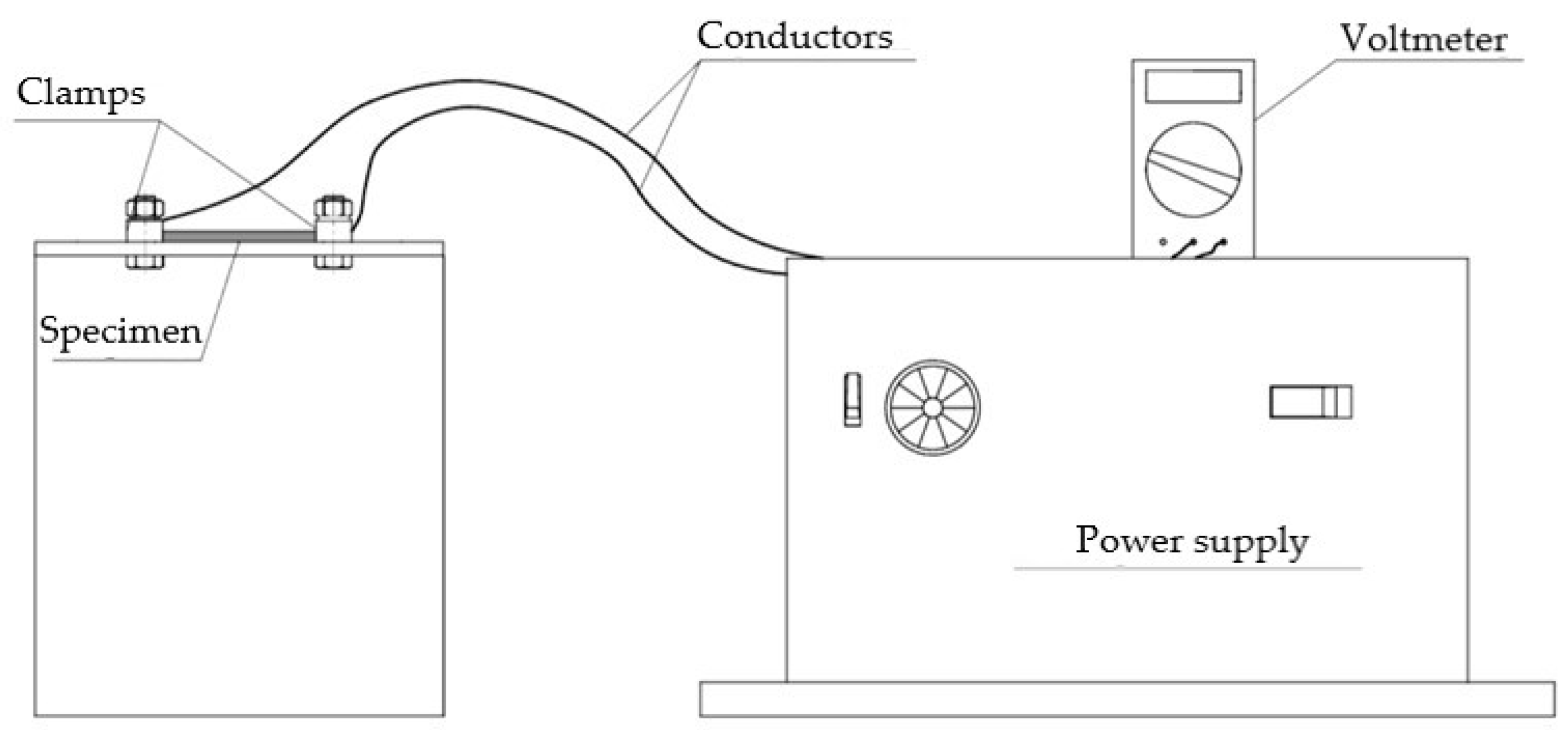
Figure 2.
Microstructure of 09G2S steel in its initial state in BSE mode.
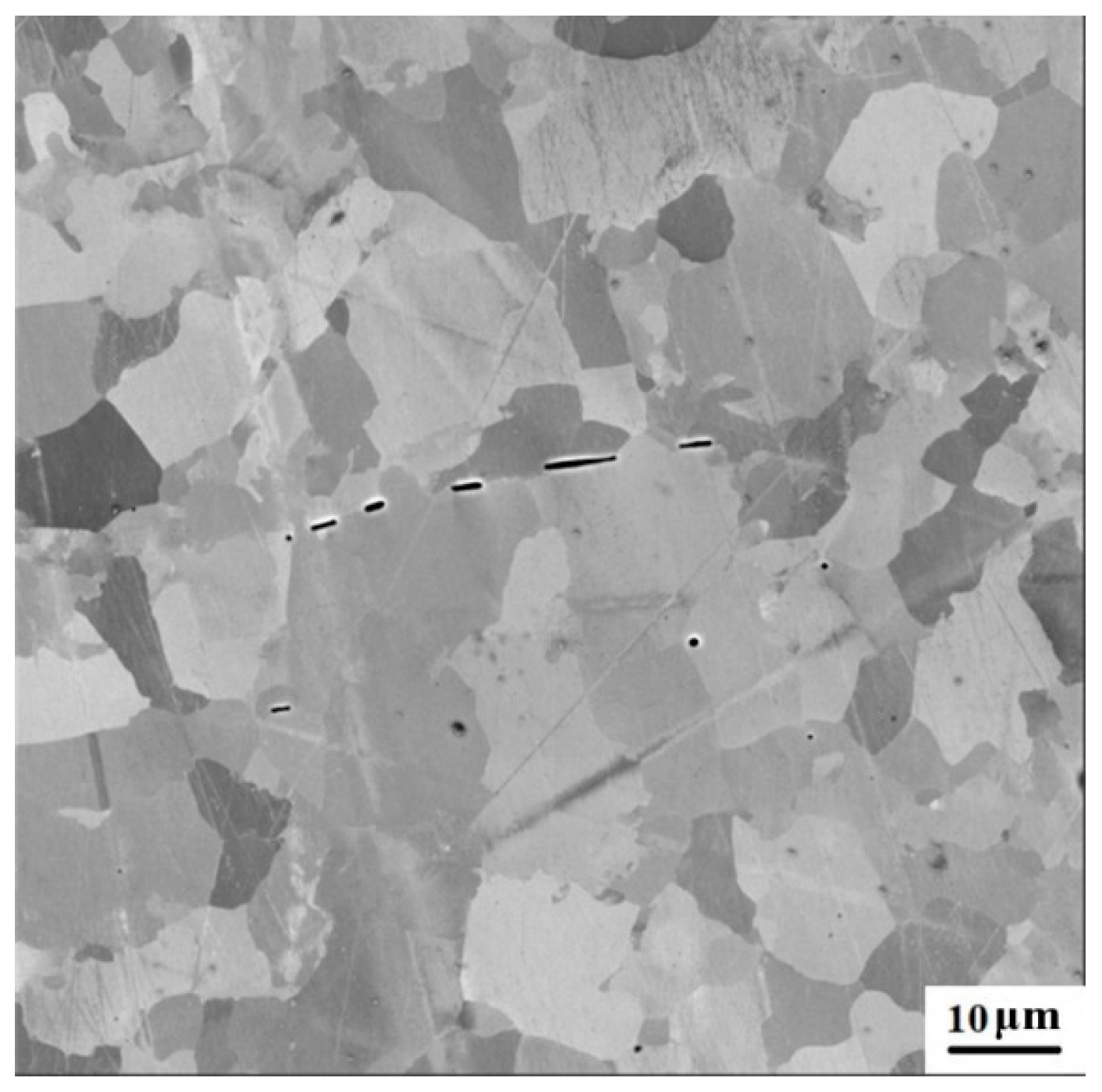
Figure 3.
Structure after fatigue test: a – SEM image of a main fatigue crack, b – SEM image of a section with carbide near a crack in SE mode, c – SEM image of a section with carbide near a crack in BSE mode. In (a) the rectangle area presented in (b) and (c) is shown.
Figure 3.
Structure after fatigue test: a – SEM image of a main fatigue crack, b – SEM image of a section with carbide near a crack in SE mode, c – SEM image of a section with carbide near a crack in BSE mode. In (a) the rectangle area presented in (b) and (c) is shown.
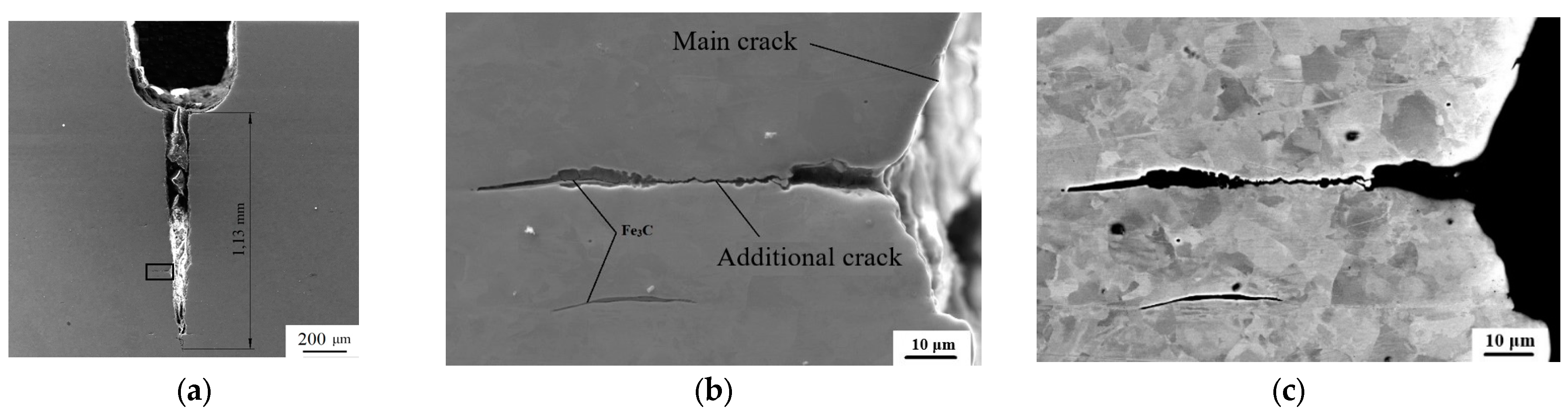
Figure 4.
Optical image of the crack healed by six current pulses.
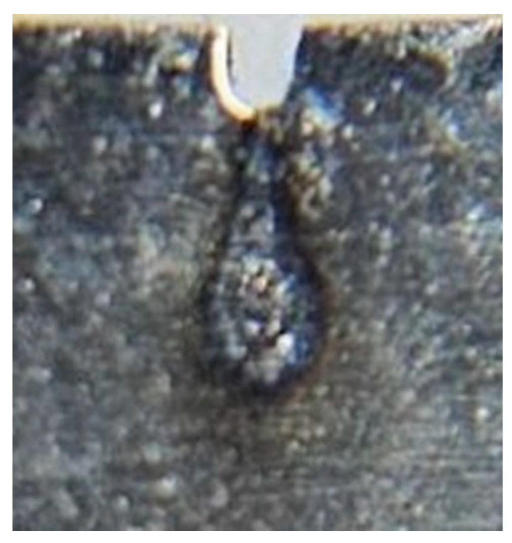
Figure 5.
SEM images of the microstructure after crack healing: (a) – at a depth of 0.1 mm from the surface and (b) – at a depth of 0.5 mm from the surface (the middle plane of the specimen).
Figure 5.
SEM images of the microstructure after crack healing: (a) – at a depth of 0.1 mm from the surface and (b) – at a depth of 0.5 mm from the surface (the middle plane of the specimen).
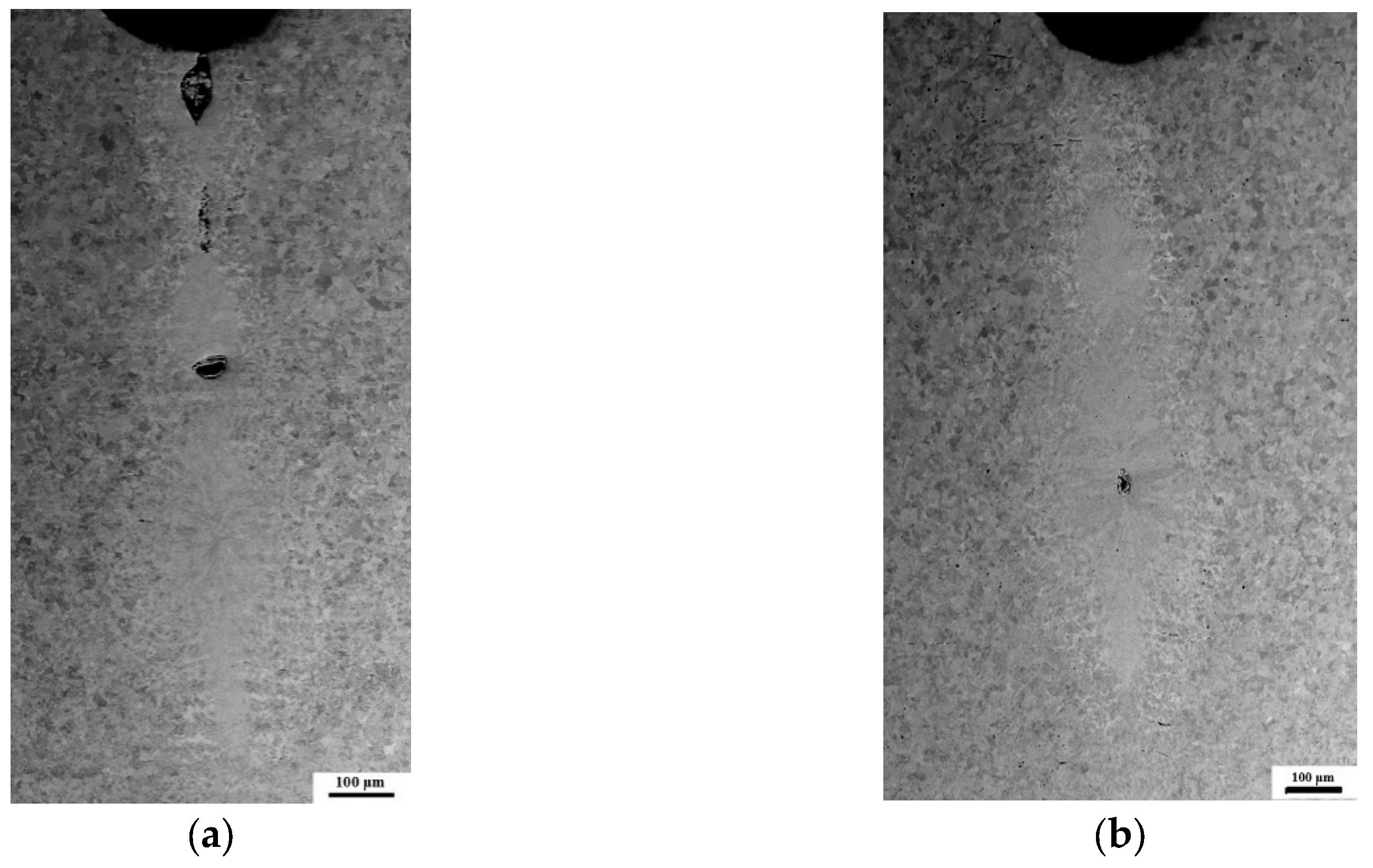
Figure 6.
Three zones in the sample after pulsed current treatment: MZ – melting zone, HAZ – heat-affected zone, BMZ – base metal zone.
Figure 6.
Three zones in the sample after pulsed current treatment: MZ – melting zone, HAZ – heat-affected zone, BMZ – base metal zone.
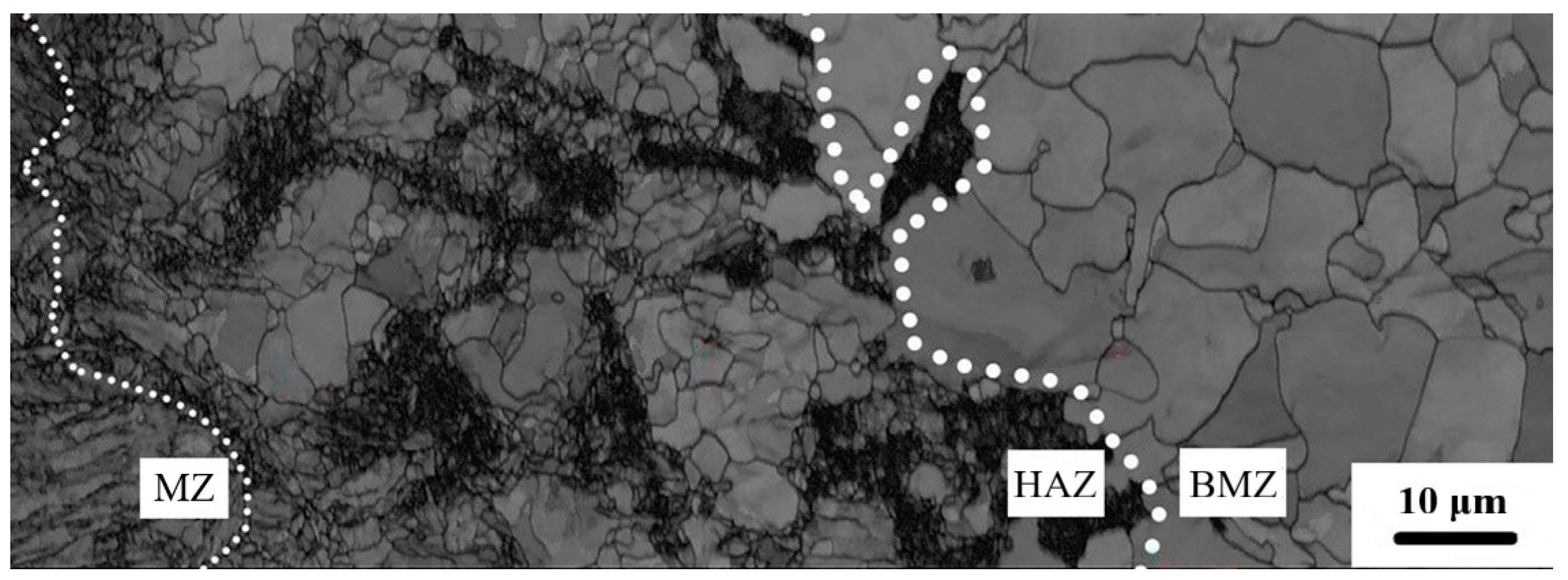
Figure 7.
SEM-images in BSE mode of: (a) – melting zone (MZ), (b) - heat-affected zone (HAZ).
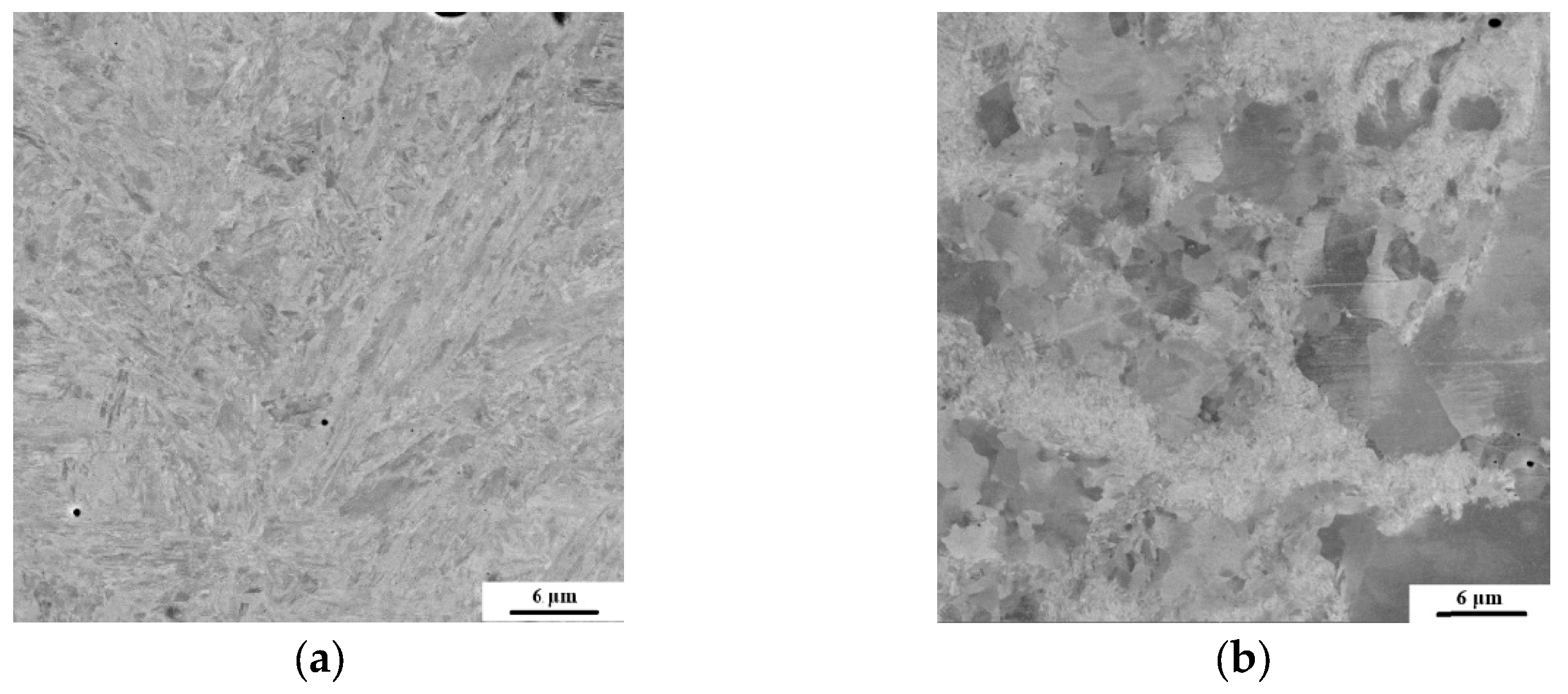
Figure 8.
Heat-affected zone in Band Contrast mode.
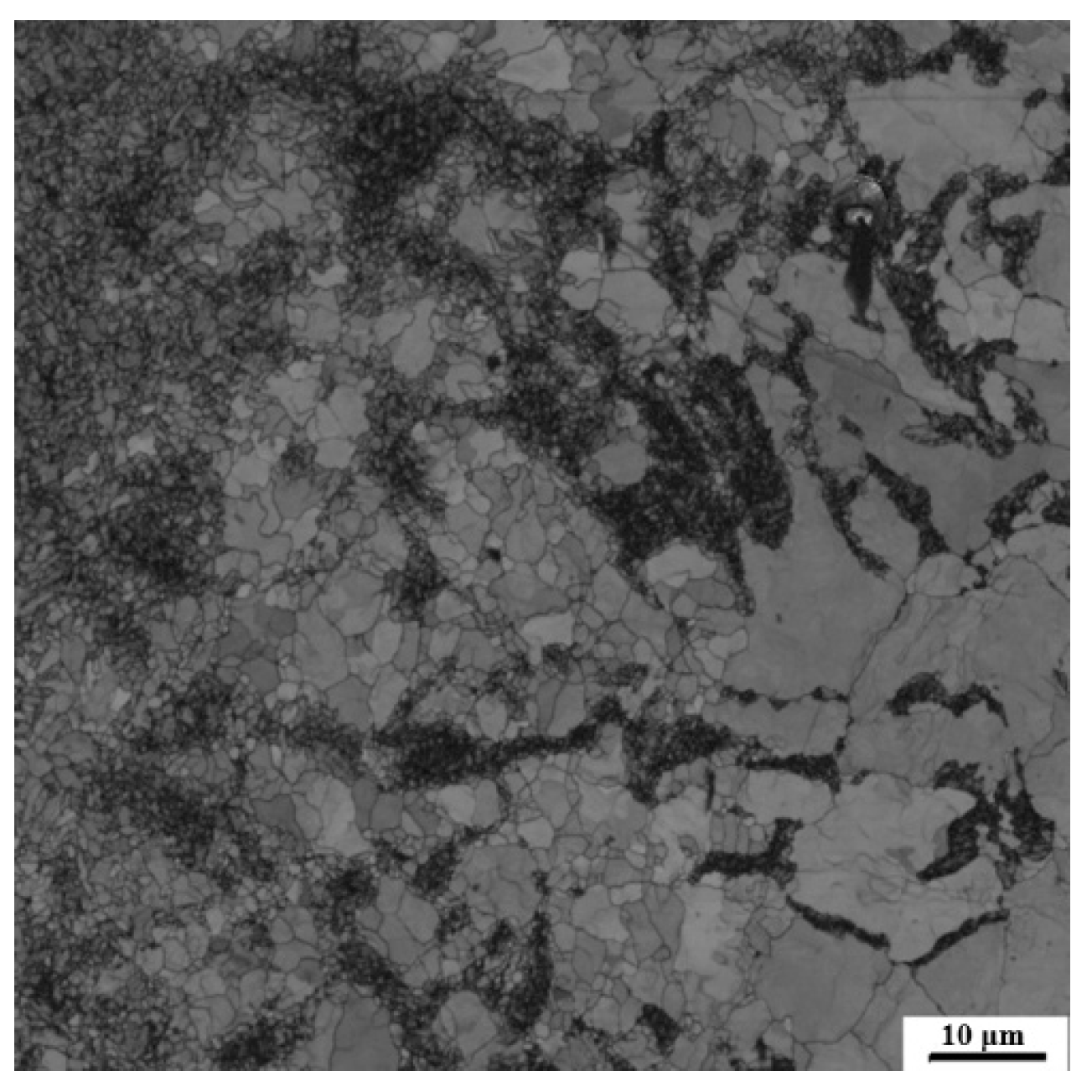
Figure 9.
Measurement of the microhardness of the sample after healing of the crack: (a) – map of the points at which measurements were taken, (b) – distribution of microhardness along the direction normal to the healed crack.
Figure 9.
Measurement of the microhardness of the sample after healing of the crack: (a) – map of the points at which measurements were taken, (b) – distribution of microhardness along the direction normal to the healed crack.
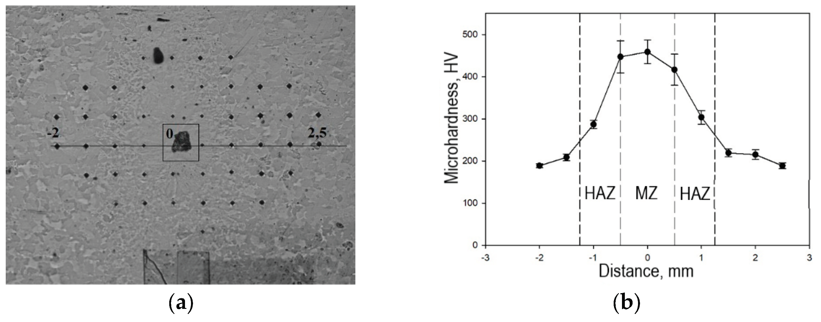

Table 1.
Chemical composition of 09G2S steel.
| Mass fraction of elements, wt. % | |||||||||
|---|---|---|---|---|---|---|---|---|---|
| C | Si | Mn | P | S | Cr | Ni | V | Cu | Fe |
| < 0.12 | 0.5 -0.8 | 1.3 – 1.7 | < 0.03 | < 0.035 | < 0.3 | < 0.3 | < 0.12 | < 0.3 | other |
Disclaimer/Publisher’s Note: The statements, opinions and data contained in all publications are solely those of the individual author(s) and contributor(s) and not of MDPI and/or the editor(s). MDPI and/or the editor(s) disclaim responsibility for any injury to people or property resulting from any ideas, methods, instructions or products referred to in the content. |
© 2025 by the authors. Licensee MDPI, Basel, Switzerland. This article is an open access article distributed under the terms and conditions of the Creative Commons Attribution (CC BY) license (http://creativecommons.org/licenses/by/4.0/).
Copyright: This open access article is published under a Creative Commons CC BY 4.0 license, which permit the free download, distribution, and reuse, provided that the author and preprint are cited in any reuse.


