
Submitted:
09 November 2025
Posted:
10 November 2025
You are already at the latest version
Abstract
The present article relates to the description of phenomenological relations of amorphous material behavior within the framework of viscoelasticity and elastic-viscoplasticity theory, as well as to the creation of its digital analogue. Ultra-high-molecular-weight polyethylene (UHMWPE) is considered in the study. The model is based on the results of a series of experimental studies. Free compression of cylindrical specimens in a wide range of temperatures [-40; +80] °C and strain rates [0.1; 4] mm/min was performed. Cylindrical specimens were also used to determine the thermal expansion coefficient of the material. Dynamic mechanical analysis (DMA) was performed on rectangular specimens using a three-point bending configuration. Maxwell and Anand models were used to describe the material behavior. In the framework of the study, a temperature dependence of a number of parameters was established. This influenced the mathematical formulation of the Anand model, which was adapted by introducing the temperature dependence of the activation energy, the initial deformation resistance, and the strain rate sensitivity coefficient. Testing of the material models was carried out in the process of analyzing the deformation of a spherical bridge bearing by a multi-cycle periodic load. The load corresponds to the movement of a train on a bridge structure, without taking into account vibrations. It is shown that the viscoelastic model does not describe the behavior of the material accurately enough for quantitative analysis of the stress-strain state of the structure. It is necessary to move on to more complex models of material behavior to minimize the discrepancy between the digital analogue and the real structure. It is established that taking into account plastic deformation while describing UHMWPE allows this to be done.
Keywords:
amorphous material
; UHMWPE
; viscoelasticity
; elastic-viscoplasticity
; spherical bridge bearing
; polymer sliding layer
; plastic deformation
1. Introduction
1.1. Target of Research
The purpose of the present work is to create a viscoelastic and elastic-viscoplastic behavior model of low-friction polymer materials and to perform their comparative analysis. The study employs an experimental methodology for investigating such materials, implemented here using ultra-high-molecular-weight polyethylene (UHMWPE) as an example. The article also provides a description of phenomenological relations for the stress-strain state of the material within the framework of viscoelasticity and elastic-viscoplasticity over a wide range of operating temperatures. Testing of the material behavior models was carried out using the example of multi-cycle deformation of a spherical bridge bearing with an antifriction UHMWPE layer.
The objectives of the study include:
1. Performing a series of experimental studies of deformation behavior of UHMWPE specimens, specifically: dynamic mechanical analysis (DMA); measuring the thermal expansion coefficient (CTE); free compression of cylindrical specimens.
2. Determination of phenomenological relationships to describe material behavior in modern computer-aided design (CAD) systems, taking into account experimental data.
3. Formation of vectors of unknown parameters of viscoelastic and elastic-viscoplastic models for further identification. Creation of numerical analogues of experiments for verification of model identification results. Identification of phenomenological relation parameters based on experimental data.
4. Approbation of the digital analogue of the material in the context of the problem of multi-cycle deformation of a spherical bridge bearing with a sliding layer made of UHMWPE.
5. Analysis of the influence of UHMWPE mathematical models on the stress-strain state of the antifriction layer of a spherical bridge bearing.
Complex phenomenological models will help to minimize the discrepancy between the real structure and its numerical analogue. Experimental studies in a wide temperature range will make it possible to evaluate the thermomechanics of the antifriction material.
1.2. Problem Context and Description
Polymers with antifriction properties are widely used in many fields of human activity [1,2,3,4]. Materials of this type are used as coatings and interlayers to minimize wear of the interface surfaces of the elements. A distinctive feature of antifriction materials is their friction coefficients, which are less than 0.2. They may be significantly lower than 0.2 and be only 0.01 or less under various operating conditions [5,6]. Such materials are used as relatively thin protective, protective-strengthening, and antifriction coatings and interlayers in various fields of science and technology. Antifriction materials in friction units can increase the durability and reliability of the structure, its service life, and overhaul periods.
Active development of the polymer industry makes it possible to replace conventional materials with polymers [7,8,9], which leads to the positive effects: weight reduction, increased wear resistance, improved friction properties, etc. Thus, the authors of [9] describe the revolutionary developments of the polymer industry in the field of increasing the strength and reducing the weight of the material. The role of polymers in future innovations is also emphasized. However, the introduction of new materials often entails changes in the technological process, system geometry, and technical documentation [10,11]. This, in turn, raises a question of mathematically describing the behavior of the materials in conditions close to operational conditions for creating digital analogues [12]. However, formulation of the numerical analogues of the materials requires a large amount of experimental data and the implementation of a rather complex mathematical apparatus [13,14,15].
Polytetrafluoroethylene (PTFE) is widely used among the antifriction materials [16,17,18]. The material has the best anti-friction properties compared to analogues under high loads, heat resistance, etc. However, it has limitations in use due to its high wear rate and low yield strength. This is particularly evident in the systems operating under multi-cycle loading [19,20]. Nowadays, PTFE is being replaced with new materials. UHMWPE is one of the possible alternatives to PTFE [21,22,23]. It demonstrates better physical and mechanical properties [24,25,26] and also has a wider operating temperature range.
The lack of information on the properties of antifriction polymers and composites is still noted [27,28,29]. It is largely due to the constant improvement of the material formulations, as well as the emergence of new manufacturers and new materials [30]. This significantly reduces the prospects of using new materials in the industry. Quite a large number of experimental studies are required to evaluate the behavior of the materials and formulate their numerical analogues. The main types of experimental studies are: DMA [31,32]; thermomechanical analysis [15,33]; constrained/free compression [34]; tribological testing [35,36]; chemical analysis [37,38], etc. An experimental study allows for an initial assessment of the possibility of using the material in certain technological processes and operating conditions. However, for a quality-assuring approach, a synergy is used between the experimental study and formulation of a numerical analogue of the material (of a structure, a system) [39,40].
Mathematical models qualitatively and quantitatively characterizing the behavior of materials are necessary to formulate a numerical analogue of structures and systems with minimal differences from reality. The list of mathematical models that can be used to characterize polymers and composites is quite wide. These are models describing materials within the framework of elastoplasticity theory [28,41], viscoelasticity theory [28,42], and elastic-viscoplasticity theory [43,44]. Elastoplastic models can describe the behavior of a material both qualitatively and quantitatively. However, they are limited to static problems [28]. Models of viscoelasticity and elastic-viscoplasty theory should be used to predict material performance, taking into account the time factor. However, using complex models increases the cost of computing resources. To minimize the cost of computing resources, a preliminary evaluation of the models’ performance can be carried out in planar and axisymmetric formulations. Two behavior models of the antifriction material were considered in the current study: the viscoelastic model (Maxwell body) and the elastic-viscoplastic model (Anand model).
Analysis of the deformation behavior of an L-100 spherical bridge bearing with a polymer sliding layer is considered for testing the UHMWPE behavior models [27]. A bridge bearing is an important structural element. A bridge bearing determines the maintenance-free service life of bridgework as a whole [45,46,47]. Mathematical simulation of the antifriction layer material behavior makes it possible to evaluate the operation of the structure in regular and emergency situations [27,45]. Replacement of the antifriction layer material can also be considered using digital analogues of the material and design [9].
An experimental research method providing a possibility of automatically identifying the parameters of mathematical models was developed. Viscoelastic and elastic-viscoplastic material behavior models are based on experimental data. A digital analogue of a spherical bridge bearing, taking into account the multi-cycle loading, was formulated to test the models. A multivariate analysis of the antifriction layer material behavior for various mathematical models describing its behavior was carried out.
2. Materials and Methods
2.1. Experimental Study
A series of experimental studies must be carried out to determine the mathematical model of the material. Two main types of experiments were selected: DMA and CTE determination using DMA Q800 (TA Instruments; New Castle; Delaware; USA) (see Figure 1a); and uniaxial stress state (USS) testing using Instron 68SC-5 (Instron® Corporation; Norwood; Massachusetts; USA) (see Figure 1b). A thermal field at sub-zero temperatures was created using liquid nitrogen as part of experiments on a DMA Q800 unit. A 24-hour exposure at a preset temperature in an ST-64-70H temperature chamber (SONACME Technology Co, Guangdong, China) was used to record the temperature during the USS experiment. An AVE2 video extensometer (Instron® Corporation; Norwood; Massachusetts; USA) was used to record the results of the uniaxial compression testing.
Cylindrical specimens 4×4 mm were used in the experiments for uniaxial compression and CTE determination. Rectangular specimens with average dimensions of 60×12×3 mm were used in DMA tests. A temperature range of −40 ℃ to +80 ℃ was considered. To ensure the static significance of the results, at least 3 tests were conducted for each type of thermal strength loading. Experimental studies were conducted on UHMWPE specimens (AlfaTech LLC, Perm, Russia). These specimens for experimental testing are shown in Figure 2.
Brief experimental procedure:
- DMA: Testing of the specimens is carried out according to the three-point bending principle. The specimens are fixed with two clamps equipped with roller bearing supports. This eliminates the clamping effect when the specimen is deformed. Gradual heating of the specimen to +80 °C takes place in the measuring unit chamber during the 1st stage of the experiment. The heating time is 20 minutes. After reaching the required temperature, the specimen is kept at +80 °C for 10 minutes. An oscillating load is applied to the center of the specimen in the 2nd stage of the experiment. The frequency of exposure is 1 Hz. Gradual cooling to −40 °C is carried out in increments of 2 °C/min.
- TEC: Testing of the specimens is carried out according to the free compression principle. Cylindrical specimens are placed in compression clamps. To minimize compressive strain, a load of 0.005 N is applied to the specimen. The load does not exceed 0.001% at a temperature of +80 °C. This allows the specimen to be more subject to thermal deformation. For the material under consideration, CTE in the studied temperature range is assumed to be constant. This is due to the fact that the glass transition temperature does not fall within the temperature range from −40 °C to +80 °C (according to DMA results). At the first stage, the specimen was cooled from room temperature to −40 °C. At the second and third steps of the experiment, the specimen was gradually heated to +20 °C and +80 °C, correspondingly, with recording the temperature deformations of the specimen.
- USS: Testing of the specimens is carried out according to the free compression principle. Before testing, the specimens were kept for 24 hours at the preset temperature in a specialized thermal chamber. Additional elements and media were used for forming the interface of the specimens with the press plates to minimize friction and barrel distortion: TsIATIM-221F grease and teflon film. The scheme of connecting the specimen with the experimental unit plates is as follows: grease – teflon film – grease – specimen. This treatment pattern was used on all mating surfaces. The following four strain rates were considered: 0.1 mm/min (2.5%/min), 1 mm/min (25%/min), 2 mm/min (50 %/min), and 4 mm/min (100 %/min).
DMA makes it possible to obtain data without leaving the linear viscoelasticity zone. This provides a means for characterizing the material using simple models, such as a generalized Maxwell body [48]. In the experiment, the specimen is subjected to periodic action with a frequency of 1 Hz with a temperature change of 2 °C/min. The time dependence of stress (1) and strain (2) is as follows:
where is maximum specimen stress; is maximum specimen strain; is lag angle. The last parameter characterizes the phase shift of stress and strain. A graphic illustration of the phase shift is shown in Figure 3.
The phase shift angle is a parameter for evaluating the viscoelasticity of the material. A body has viscoelasticity properties if the phase shift angle is in the range . This parameter makes it possible to go to the Young modulus components:
where is a storage modulus, and is a loss modulus. The storage modulus shows the effect of the elastic part on the deformation behavior of the specimen, and the loss modulus shows the effect of its viscous part.
The complex elastic modulus is determined by formula (5) via and :
Studying the material only within the linear theory is the main limitation. It can result in large discrepancies with respect to the actual behavior of the material, since plasticity is observed in materials of this class [49]. Taking into account the plastic deformation of the material plays an important role in obtaining a high-quality digital analogue.
A series of USS experiments at various temperatures and strain rates was conducted to determine the level of plastic deformations. During the experiments, the actual displacement values were recorded. The forces were determined on the crosshead, and for the transition to stress and strain, the following relationships were used:
where is a force on the crosshead; is a contact surface area; is the specimen height change; is the initial specimen height.
2.2. Mathematical Models of Material Behavior
The specification of mathematical models of materials’ behavior is an important trend in computer engineering development. A high-quality specification of materials’ behavior makes it possible to predict the behavior of the structure with greater accuracy. Identification of the empirical parameters of mathematical models is based on the author’s algorithm [32]. To do this, it is necessary to form a vector of unknowns for each of the considered material behavior models.
2.2.1. Viscoelastic Model
The viscoelastic model is widely used to describe the behavior of amorphous materials [50,51]. A Maxwell body is one of the most common models [52]. The model makes it possible to describe the time dependence of the complex elastic modulus. The general form of the defining relation is:
where is the Cauchy stress tensor; is strain deviator; is volumetric deformation; I is unit vector; , and are shear modulus and bulk compression modulus, correspondingly.
Due to the condition of the constancy of the bulk compression modulus, relation (8) takes the form (9):
Prony series are used to describe the dependence of the shear modulus on time:
where is the initial value of the shear modulus at t = 0; is relative shear modulus; is the number of members of a series; is relaxation times. From the conditions , it follows that , . The reference time is used to describe the temperature effect:
where is Williams-Landel-Ferry (WLF) temperature-time similitude; , and are empirical constants; is temperature at a current moment of time; is glass transition temperature. Taking into account the WLF temperature-time similitude, relation (10) takes the form:
For the transition to the elastic modulus, we use relation (10):
where is the initial value of the shear modulus at t = 0; is the relative elasticity modulus.
Let us assume that the relaxation times for shear and tension/compression coincide. Then the relation for the relative elastic modules can be represented as:
where . The dependence of the initial and final shear modulus on elastic modulus has forms , . The Poisson ratio at the final time moment can be found from the relation . This is due to the constancy of the bulk compression modulus . The formula for determining the Poisson ratio at the final time moment is
The parameters of the Maxwell body viscoelastic model described with the Prony series can be found from the tension/compression experimental data. The defining relation in the case of uniaxial tension/compression takes the form (16):
Taking into account formula (2), relation (16) can be transformed to the form (17):
Similar to (3) and (4), the storage modulus (18) and loss modulus (19) will have the form
The storage modulus and loss modulus are determined experimentally.
The vector of unknowns for the model being considered will have the form:
2.2.2. Elastic-Viscoplastic Model
The Anand model is actively used for describing the elastic-viscoplastic behavior of various materials [53,54,55]. The possibility of a more accurate description of the material appears due to the consideration of activation energy, the strain rate parameter, and other empirical parameters of the model. The defining relation of the elastic-viscoplastic behavior has the form:
where is the tensor of viscoplastic strain rate; is equivalent viscoplastic strain rate; is stress deviator; is mean stress; is equivalent stress. The equivalent viscoplastic strain rate is formulated with a number of empirical parameters:
where is the Arrhenius equation, defining viscosity by the expression ; is pre-exponential factor; is activation energy; is universal gas constant; is absolute temperature; is yield strength initial value; is strain rate sensitivity factor; is empirical constant.
The evolutionary equation for yield strength has the form (23):
where is the hardening/softening parameter; is the strain rate sensitivity factor for hardening/softening; is yield strength saturation parameter; is rate to yield strength change sensitivity parameter.
The vector of unknowns for the elastic-viscoplastic model has the form:
The standard Anand model has limitations when describing amorphous materials [56]. To improve the quality of the material behavior description, the dependence of a number of parameters on temperature will be introduced into the model: of activation energy (27), of yield strength (28), and of the strain rate sensitivity factor (29).
where are the empirical parameters of relations (27)-(29).
The resulting vector of unknowns of the elastic-viscoplastic model takes the form:
2.3. Spherical Bridge Bearing Model
Deformation behavior analysis of a spherical bridge bearing L-100 (AlfaTech LLC, Perm, Russia) was performed for various behavior models of the UHMWPE antifriction layer. The problem is considered in an axially symmetric formulation and includes a contact assembly comprising a top steel plate with a polished spherical segment (1), a bottom steel plate with a spherical cutout (2) for the antifriction layer (3) (see Figure 4). The model does not take into account cavities for lubricant in the antifriction layer (3). The axially symmetric model of the structure allows testing material behavior models of the antifriction layer under different loading conditions without any significant computational power costs.
The overall dimensions of L-100: total height 54 mm , width and depth 155 mm ; the height of the layer edge not contacting with the bottom steel plate (the antifriction layer protrusion) is approximately 2 mm, the antifriction layer slope angle is °.
At the interfaces of the antifriction layer with steel elements of the structure, a friction contact is implemented with an unknown in advance distribution pattern of the contact state zones (sticking, slipping, non-contact) [57]. The mathematical formulation of the problem and the analysis of the system digitalization degree effect on the numerical solution were previously described in [58]. The characteristics of the finite element scheme, as well as finite elements and characteristic features of the problem simulation, are considered in [57]. The problem was implemented using the finite element method in ANSYS Mechanical APDL 2021R2 (Livermore, CA, USA).
Cyclic loading of the bridge bearing is considered to analyze the operation of the material model considered in the context of viscoelasticity and elastic-viscoplasticity theory. The loading cycle is shown in Figure 5.
A sinusoidal increase in the load level takes place once in 10 minutes loading cycle: the minimum level corresponds to the absence of load from transport on the bridge bearing; a sinusoidal increase in the load corresponds to transport passing along the bridge bearing. The model makes it possible to estimate the stress-strain state of the structure in a first approximation for various behavior models of the antifriction layer under multi-cycle loading conditions.
3. Results
3.1. Experimental Studies
3.1.1. Dynamic Mechanical Analysis
The characteristics of the storage modulus , loss modulus , and the loss angle tangent, defined with the formula , were obtained in a series of tests. The average characteristics are presented in Figure 6.
The storage modulus decreases as the temperature increases. As the elastic modulus decreases, the material becomes more plastic. The conclusion that the glass transition/softening temperature of the UHMWPE material does not fall within the range under consideration can be made by analyzing the change in the loss modulus and the loss angle tangent.
3.1.2. Free Compression of the Cylindrical Specimens
In the series of conducted experiments, all tested specimens were subjected to 10% deformation from their original height at various strain rates and temperatures. The specimens before and after straining are shown in Figure 7.
The difference between the experimental data in the temperature range is on average about 2–5% at a low strain rate of 0.1 mm/min. It decreases with increasing strain rate and is less than 1%. The arithmetic mean value of the experimental data for all strain rates was obtained at various temperatures. Displacement-force dependencies were recalculated to stress-strain dependencies. The free compression modulus and the Poisson ratio were obtained based on relations of Section 2 for the temperature range [−40; +80] °C.
The free compression modulus and the Poisson ratio were approximated using relations (31) and (32), correspondingly:
where , are empirical constants (see Table 1 and Table 2, correspondingly).
The obtained results are presented in Figure 8.
The elastic compression modulus decreases with increasing temperature, and the Poisson ratio increases.
3.1.3. Thermal Expansion Coefficient
UHMWPE under consideration has a stable structure in the temperature range [−40;+80] °C (determined by DMA), and therefore, CTE was measured at two control points: −40 °C and +80 °C. The discrepancy between the measurement results is less than 1%. The average value .
3.2. Identification of Mathematical Models
Based on experimental data, material behavior model parameters were obtained. Identification was performed as part of a parameterized optimization algorithm. The algorithm includes the possibility of choosing: a) the simulation model of experiments (three-point bending, free compression); and b) the material behavior model. The iterative procedure of searching parameters of the vector of unknowns is stopped when the difference between experimental data and simulation model becomes less than 5%.
3.2.1. Maxwell Model Based on the Prony Series
A single vector of unknown parameters is determined for the entire temperature range. The dependences of the relative shear modules on the relaxation time were determined (see Figure 9).
The effect on the change in the material shear modulus decreases with increasing relaxation time. The total impact on the change in shear modulus does not exceed 2% with a relaxation time of seconds.
3.2.2. Anand Model
The parameters of the Anand elastic-viscoplastic model were also determined. The dependence of the yield strength initial value on temperature is one of the key factors. The stress level for exiting the elasticity theory can be estimated based on the following parameter (see Figure 10).
The yield strength initial value depends on temperature non-linearly. The parameter value decreases with a damping effect as the temperature increases. This may indicate that the yield strength initial value will not be lower than 0.8 MPa with increasing temperature. A rapid increase in yield strength is observed with decreasing temperature. This indicates that the material is close to its glass transition/softening temperature. However, it does not fall within the range being considered. Further experiments will be required to determine the glass transition/softening temperature in future studies. This will cause additional difficulties in generating sub-zero temperatures of less than −40 °C in experiments using liquid nitrogen.
The activation energy temperature dependence is shown in Figure 11.
Activation energy dependence on temperature is close to linear. Its parameter corresponds to the range of values of polyvinylchloride, which relates to amorphous materials.
Figure 12 demonstrates the temperature dependence of the strain rate sensitivity factor.
The strain rate sensitivity factor has a slight variation of values within the temperature range, less than 0.01%. It can be considered as constant if necessary. This will entail an additional minor error when simulating the material behavior of actual structures and systems.
3.3. Numerical Simulation of the Stress-Strain State of an L-100 Spherical Bridge Bearing with Various Antifriction Layer Material Models
The analysis of the material behavior of the L-100 bridge bearing in an axisymmetric formulation for multi-cycle loading was conducted in the present study. This was done as part of testing and evaluating thermomechanical models of UHMWPE, which was used as an antifriction layer. The multi-cycle loading effect on the deformation behavior of the material was considered for the constant temperature field. The behavior of the antifriction layer structure and material in the first approximation was considered for three temperatures −40 °C, +20 °C, and +80 °C.
The dependence of the bridge bearing settlement on the number of loading cycles is illustrated in Figure 13.
The distribution pattern of vertical displacement of the bridge bearing (the settlement) is nonlinear. Fluctuations of the parameter are associated with the solution of the contact problems and redistribution of the contact statuses in the course of the iterative solution procedure. The settlement reaches an asymptote with an increase in the number of loading cycles. The maximum level of the bridge bearing vertical displacement with an elastic-viscoplastic model of the material is larger than with a viscoelastic model. This is due to taking into account the plastic deformation of the material, which is observed in this class of materials [59]. The discrepancy between the results decreases at elevated temperatures. The obtained level of maximum vertical displacement of the bearing is consistent with data obtained from static and cyclic laboratory and field tests [60,61].
The dependence of the maximum normal displacements of the relative free edge of the antifriction layer on the number of loading cycles is illustrated in Figure 14.
The dependence of the maximum displacement level of the end face of the antifriction layer on the number of loading cycles is nonlinear. Fluctuations of the parameter are associated with changes in the distribution pattern of the contact statuses on the interface surfaces. The maximum normal displacements of the elastic-viscoplastic model are, on average, 70% higher. The viscoelastic model significantly underestimates the level of the relatively free edge of the antifriction layer.
The elastic-viscoplastic model makes it possible to estimate non-reversible deformations of the antifriction layer. This is its significant advantage over the viscoelastic model. The most dangerous area for the occurrence of such deformations is a stress concentrator in the form of a metal shoulder of the bottom steel plate, contacting with the antifriction layer. The dependence of the maximum plastic deformation values of the antifriction layer on the number of loading cycles is shown in Figure 15.
The growth of plastic deformations results in an increase in the other parameters of the stress-strain state of the structure. Localization of plastic deformations indicates a risky area of the structure: the metal shoulder of the bottom steel plate. When evaluating the geometry of this part of the structure, the operability of the structure should also be assessed in further studies. The level of plastic deformations in the bulk volume of the sliding layer material is insignificant, less than 1% (see Figure 16).
The level of plastic deformations does not exceed 1% in the central part of the layer. The level of plastic deformations near the end face of the layer after 2000 loading cycles is about 9% (without taking into account the stress concentrator). Without taking into account plastic deformations of the material, it is possible to obtain overestimated stress values in the polymer antifriction structure. This is confirmed by the current results (see Figure 17).
In the viscoelastic model, the equivalent stress strongly increases with increasing the number of loading cycles. However, in the elastic-viscoplastic model of the antifriction layer material, the equivalent stress value significantly decreases with an increase in the number of loading cycles. This indicates a softening of the material during the deformation process. These effects are caused by the presence of a stress/strain concentrator.
The pattern of the stress distribution over the volume of the antifriction layer and maximum values localization zone are consistent with the data obtained by Deng et al. [62]. The PTFE antifriction layer responds the temperature change in a different way [62]: increasing temperature results in a decrease in the level of the stress-strain state parameters. This may be due to the fact that the glass transition/softening temperature of the material falls within the considered temperature range [−10;+20] °C.
Using the material behavior models in the framework of the viscoelasticity theory leads to significant underestimation of the deformation level parameters and overestimation of the stress state parameters. The viscoelastic material behavior model of the antifriction layer has a large number of limitations when analyzing the behavior of real structures.
4. Discussion
4.1. Limitation Statement
For the current study, the following limitations were set:
- The temperature range from −40 °C to +80 °C was considered. However, in the bridgeworks, temperatures may occur that fall outside the range under consideration [63,64].
- There is no experimental study of the stress concentrator and its geometry effect on the destruction of the polymer sliding layer.
- No studies of material creep and relaxation have been conducted, but this is important for forming a material behavior model with minimal deviation from reality [65,66,67,68].
- Deformation of the structure is considered in an axisymmetric formulation, which does not allow taking into account cavities for lubricant in the antifriction layer in the form of spherical indents.
4.2. On the Possibility of Replacing the “Plastic King” with Modern Polymers and Composites
PTFE has been used as the antifriction layer material of bridge bearings and pivot mechanisms for decades since the beginning of the design of steel balance beams [2,73]. New and modified bridge bearing structures are also designed with an antifriction layer made of PTFE [62,74]. However, cases of bearing failure due to plasticity or creep of the antifriction sliding layer during loading from the bridge span are noted [75]. The stress-strain state of a structure with a PTFE antifriction layer is significantly inferior to analogues with antifriction layers made of modern antifriction materials. The level of the normal displacements of the end face of the layer made of this material is 25–30% higher than in structures using composites based on it, and 85–90% higher when modern antifriction materials are used [73]. A permanent increase in the tonnage of bridgeworks has further revealed the shortcomings of PTFE antifriction layers [2]. PTFE limitations and the need to modify it by introducing various additives or replacing it with modern polymers and composites are comprehensively discussed by the scientific community [76,77,78]. UHMWPE is considered as an alternative to PTFE, including for the purposes of friction units [2,20,79,80], because it can better retain its shape and structural integrity, is more resistant to erosion, has improved shear strength, etc.
World leaders in the design and manufacture of bridge bearings, MAGEBA SA (Bulach, Switzerland) [81] and MAURER SE (Munich, Germany) [82], are also abandoning the use of PTFE as a sliding layer. The highly-durable and wear-resistant material based on modified high-molecular-weight polyethylene ROBO®SLIDE is used by MAGEBA SE for antifriction layers [81]. Modified UHMWPE with various additives MAURER Sliding Material (MSM®) is a patented material of the bridge bearing sliding layers manufactured by MAURER SE [82,83,84]. However, Adamov et al. note the lack of data on the properties of the materials considering operating temperatures and nonlinear effects in the public domain [5]. This is a limiting factor for the implementation of UHMWPE, its compositions and modifications, as well as the other alternatives in friction units. The current material provides data on the thermomechanical and physicomechanical properties of one of the UHMWPE variants. The data can form the basis for digital analysis of the possibility of using UHMWPE as coatings and antiftiction layers for highly loaded friction units.
Currently, UHMWPE can be compared with PTFE within the DMA (see Figure 17). The experiments have been fully conducted and processed.
Figure 17.
Comparison of the experimentally determined thermomechanical properties of PTFE and UHMWPE: a is storage modulus; b is loss modulus.
Figure 17.
Comparison of the experimentally determined thermomechanical properties of PTFE and UHMWPE: a is storage modulus; b is loss modulus.

PTFE glass transition/softening temperature falls into the temperature range being considered. This is indicated by a decrease in the storage modulus and a peak of the loss modulus observed in the temperature range from 0 to 20 °C. The glass transition/softening temperature is 8–14 °C, depending on different definition theories. PTFE is less resistant to temperature changes. The material changes from a glassy state to a rubbery state in the operating temperature range of the bridge bearing. In the range of +30 °C, UHMWPE exhibits a higher elastic response than PTFE. The viscosity of UHMWPE is higher than that of PTFE in two temperature ranges, from −40 °C to +20 °C, and from +30 °C to +80 °C.
Besides, numerical simulation of PTFE viscoelastic behavior was performed. Free compression tests and CTE determination of the material must be carried out. They are planned for the end of 2025 – beginning of 2026. Comparative analysis of the materials will be carried out as part of the study development after formation of the modified Anand model for PTFE based on an identical set of experimental data. The PTFE thermal expansion coefficient will have a more complex dependence on temperature. This can be assumed since its glass transition/softening temperature falls into the temperature range under consideration. This fact will have an impact on the experiment. This would require increasing the number of control points within the experiment, as implemented by Shardakov et al. [85].
Whether it can be said that the “plastic king” [86] (PTFE) has gradually begun to lose its crown, time will show. However, the first steps toward changing the favorite in the field of antifriction polymer materials have already been made. The current work also confirms that there are materials with a more stable structure over the operating temperature range of bridgeworks. The presented materials can be widely used not only in the design of bridgeworks, but also in other branches of science and technology [1,87,88,89].
5. Conclusions
An experimental study of UHMWPE aimed at determining the thermomechanical, thermophysical, and physical-mechanical properties in a wide temperature range was carried out as a part of the current work. Phenomenological relationships of viscoelasticity and elastic-viscoplasticity were created to describe the behavior of the material. Maxwell and Anand models were selected to evaluate the feasibility of their application to describe the thermomechanics of UHMWPE. The temperature dependence of a number of parameters had to be introduced into the Anand model to modify it to minimize the discrepancy between the digital model and the test data. Vectors of unknown parameters of models for CAD systems (ANSYS, ABAQUS, etc.) were formed and identified based on the experimental data.
Material behavior models were tested within the framework of the spherical bridge bearing stress-strain state analysis under multi-cycle loading conditions. It was established that the viscoelastic model made it possible to obtain underestimated deformation characteristics and overestimated stress state parameters. Taking into account the plastic deformation of UHMWPE is necessary for forming a high-quality digital analogue of both the material and the structures and systems in which it is used.
Expansion of the phenomenological relations of the Anand model by the introduction of the temperature dependence of a number of parameters is an important part of the current work. It has been established that the viscoelastic model in the form of a generalized Maxwell body is insufficient for describing material behavior under multi-cycle loading conditions. The elastic-viscoplastic model demonstrated its efficiency and can be used to describe a number of materials, such as polymers, composites, grease lubricants, etc.
Author Contributions
Conceptualization, A.A.K., Yu.O.N., and A.P.B.; methodology, A.A.K.; software, A.A.K., A.P.B., Yu.O.N., and A.R.M.; validation, A.A.K., and Yu.O.N.; writing—original draft preparation, A.P.B., and Yu.O.N.; writing—review and editing, A.A.K., and A.R.M.; visualization, A.A.K., Yu.O.N., and A.P.B.; funding acquisition, A.P.B. All authors have read and agreed to the published version of the manuscript.
Funding
The study was supported by the Russian Science Foundation grant No. 25-29-00638, https://rscf.ru/project/25-29-00638/ (accessed on 28 October 2025).
Institutional Review Board Statement
Not applicable.
Informed Consent Statement
Not applicable.
Data Availability Statement
The original contributions presented in this study are included in the article. Further inquiries can be directed to the corresponding author.
Conflicts of Interest
The authors declare no conflict of interest.
References
- Cholewa, K.; Kurtyka, P.; Janiczak, K.; Kapis, A.; Szuber-Dynia, A.; Janecki, M.; Walke, W.; Wilk, K.; Gawlikowski, M. Mechanical and Hemocompatibility Assessment of Selected Technologies for Prosthesis Connection with the Outflow Cannula Graft of the RH PED Pediatric Pulsatile Pump for Heart Support. J. Clin. Med. 2025, 14, 4621. [Google Scholar] [CrossRef]
- Li, Y.; Guo, W.; Huang, X.; Chen, Z.; Gao, Y. Friction Characteristics and Lubrication Properties of Spherical Hinge Structure of Swivel Bridge. Lubricants 2024, 12, 130. [Google Scholar] [CrossRef]
- Liu, Q.; Xiong, J.; Lin, W.; Liu, J.; Wan, Y.; Guo, C.F.; Wang, Q.; Liu, Z. Porous polymers: structure, fabrication and application. Materials Horizons 2025, 12, 2436–2466. [Google Scholar] [CrossRef]
- Satchanska, G.; Davidova, S.; Petrov, P.D. Natural and synthetic polymers for biomedical and environmental applications. Polymers 2024, 16, 1159. [Google Scholar] [CrossRef] [PubMed]
- Adamov, A.A.; Keller, I.E.; Ostrer, S.G.; Seletkov, D.V. Evaluation of the Performance of Antifriction PTFE Composites at a Pressure Over 60 MPA. I. Comparison of Their Hardness and Deformation Properties Under Free and Constrained Compression. Mechanics of Composite Materials 2022, 58, 673–688. [Google Scholar] [CrossRef]
- Adamov, A.A.; Kamenskih, A.A.; Pankova, A.P. Numerical analysis of the spherical bearing geometric configuration with antifriction layer made of different materials. PNRPU Mech. Bull. 2020, 4, 15–26. [Google Scholar] [CrossRef]
- Xiang, S.; Long, X.; Zhang, Q.; Ma, P.; Yang, X.; Xu, H.; Lu, P.; Su, P.; Yang, W.; He, Y. Enhancing Lubrication Performance of Calcium Sulfonate Complex Grease Dispersed with Two-Dimensional MoS2 Nanosheets. Lubricants 2023, 11, 336. [Google Scholar] [CrossRef]
- Srivastav, R.S.; More, A.P. A Comprehensive Review of Self-Healing Polymers: Mechanisms, Types, and Industry Implications. Polymers for Advanced Technologies 2025, 36, 70092. [Google Scholar] [CrossRef]
- Sabet, M. Revolutionizing structures: the rise of high-performance composite and nanocomposite polymers. Polymer Bulletin 2025, 82, 4257–4306. [Google Scholar] [CrossRef]
- Shepelenko, I.; Nemyrovskyi, Y.; Stepchyn, Y.; Mahopets, S.; Melnyk, O. Creation of a Combined Technology for Processing Parts Based on the Application of an Antifriction Coating and Deforming Broaching. Lecture Notes in Mechanical Engineering 2024, 209–218. [Google Scholar] [CrossRef]
- Petrova, P.N.; Markova, M.A.; Chernykh, V.D. Investigation of Properties of Polytetrafluoroethylene-Based Composites and Carbon Fibers Depending on the Production Technology. Inorg. Mater. Appl. Res. 2024, 15, 17–25. [Google Scholar] [CrossRef]
- Gupta, S.; Iyer, R.S.; Kumar, S. Digital Twins; Springer: Cham, Switzerland, 2025. [Google Scholar] [CrossRef]
- Smetannikov, O.Yu.; Il’inykh, G.V.; Faskhutdinova, Yu.B. A model of the thermomechanical behavior of shape-memory photopolymers under thermorelaxa-tion transition conditions. Vestnik Tomskogo gosudarstvennogo universiteta. Matematika i mekhanika – Tomsk State University Journal of Mathematics and Mechanics 2025, 97, 168–183. [Google Scholar] [CrossRef]
- Vindokurov, I.; Yu, P.; Tashkinov, M.; Silberschmidt, V.V. Compression of additively manufactured PLA for biomedical applications: Effects of test conditions on properties of solid samples. Polymer Testing 2024, 130, 108320. [Google Scholar] [CrossRef]
- Jinaga, U.K.; Zulueta, K.; Burgoa, A.; Cobian, L.; Freitas, U.; Lackner, M.; Major, Z.; Noels, L. A consistent finite-strain thermomechanical quasi-nonlinear-viscoelastic viscoplastic constitutive model for thermoplastic polymers. International Journal of Solids and Structures 2025, 321, 13517. [Google Scholar] [CrossRef]
- Kamal, A.; Mosleh, A.O.; Gaafer, A.; Youness, R.A.; Taha, M.A. High-performance PTFE composites from industrial scrap with enhanced strength and wear resistance. Scientific Reports 2025, 15, 28445. [Google Scholar] [CrossRef] [PubMed]
- Yu, S.; Zhu, C.; Wu, H.; Yao, L.; Mahapatra, M.; Xu, Y. Graphite-Enhanced PTFE/PEEK composite coating for improved friction and wear resistance. Applied Surface Science 2025, 700, 163214. [Google Scholar] [CrossRef]
- Yuan, L.; Zheng, X.; Zhu, W.; Wang, B.; Chen, Y.; Xing, Y. Study on the Electrical Insulation Properties of Modified PTFE at High Temperatures. Polymers 2024, 16, 316. [Google Scholar] [CrossRef]
- Elaboudi, I.; Mdarhri, A.; Brosseau, C.; Nourdine, A.; Rzaizi, M.; Servant, L. Comparing the sorption kinetics of poly-tetrafluoroethylene processed either by extrusion or spark plasma sintering. Polymer 2020, 190, 122192. [Google Scholar] [CrossRef]
- Park, J.-H.; Lee, J.-W. Friction Behavior of Ceramic Materials for the Development of Bridge-Bearing Friction Materials. Applied Sciences 2025, 15, 152. [Google Scholar] [CrossRef]
- Savin, L.; Pinteala, T.; Mihai, D.N.; Mihailescu, D.; Miu, S.S.; Sirbu, M.T.; Veliceasa, B.; Popescu, D.C.; Sirbu, P.D.; Forna, N. Updates on Biomaterials Used in Total Hip Arthroplasty (THA). Polymers 2023, 15, 3278. [Google Scholar] [CrossRef]
- Kalácska, Á.; Parmentier, V.; De Baets, P.; Kalácska, G. Wear investigation of PTFE, PEEK and UHMWPE-based reciprocating shaft seal materials with lunar/Martian regolith stimulants. Wear 2025, 571, 205791. [Google Scholar] [CrossRef]
- Singh, D.K.; Verma, R.K. Contemporary Development on the Performance and Functionalization of Ultra High Molecular Weight Polyethylene (UHMWPE) for Biomedical Implants. Nano LIFE 2021, 11, 2130009. [Google Scholar] [CrossRef]
- Abdul Samad, M. Recent Advances in UHMWPE/UHMWPE Nanocomposite/UHMWPE Hybrid Nanocomposite Polymer Coatings for Tribological Applications: A Comprehensive Review. Polymers 2021, 13, 608. [Google Scholar] [CrossRef]
- Assma, S. Ultra-High-Molecular-Weight-Polyethylene (UHMWPE) as Desired Polymer Material for Biomedical. Khalij-Libya Journal of Dental and Medical Research 2021, 6, 11–16. [Google Scholar] [CrossRef]
- Yang, C.; Zhang, J.; Yue, H.; Kang, X. The Low Friction Coefficient and High Wear Resistance UHMWPE: The Effect of Pores on Properties of Artificial Joint Materials. Lubricants 2025, 13, 31. [Google Scholar] [CrossRef]
- Bogdanova, A.P.; Kamenskikh, A.A.; Nosov, Yu.O. The Geometric Configuration of Lubricant Recesses of the Polymer Sliding Layer of the Bearing. Designs 2023, 7( 6), 144. [Google Scholar] [CrossRef]
- Kamenskikh, A.A.; Nosov, Yu.O.; Bogdanova, A.P. The Study Influence Analysis of the Mathematical Model Choice for Describing Polymer Behavior. Polymers 2023, 15, 3630. [Google Scholar] [CrossRef] [PubMed]
- Münstedt, H. Rheological measurements and structural analysis of polymeric materials. Polymers 2021, 13, 1123. [Google Scholar] [CrossRef] [PubMed]
- Gan, Z.; Liu, J.; Xu, Z.; Jia, S.; Dong, X.-H. Precision polymers: advances in synthesis, structural engineering, and functional optimization. Progress in Polymer Science 2025, 170, 102030. [Google Scholar] [CrossRef]
- Barnes, A.H. A Handbook of Elementary Rheology; University of Wales Institute of Non-Newtonian Fluid Mechanics: Wales, 2000. [Google Scholar]
- Nosov, Yu.O.; Kamenskikh, A.A. Experimental Study of the Rheology of Grease by the Example of CIATIM-221 and Identification of Its Behavior Model. Lubricants 2023, 11, 295. [Google Scholar] [CrossRef]
- Vidakis, N.; Petousis, M.; Mountakis, N.; David, C.N.; Sagris, D.; Das, S.C. Thermomechanical response of thermoplastic polyurethane used in MEX additive manufacturing over repetitive mechanical recycling courses. Polymer Degradation and Stability 2023, 207, 110232. [Google Scholar] [CrossRef]
- Ardıç, S.; Kunt, G.; Gürgen, S.; Pat, S. UHMWPE Based Composites with CNT Fillers: Surface, Mechanical and Electrical Aspects. Materials Research Bulletin 2025, 192, 113634. [Google Scholar] [CrossRef]
- Rahman, M.; Biswas, A.S.; Hoque, K.N. Recent development on micro-texturing of UHMWPE surfaces for orthopedic bearings: A review. Biotribology 2022, 31, 100216. [Google Scholar] [CrossRef]
- Leksycki, K.; Feldshtein, E.; Maruda, R.W.; Khanna, N.; Królczyk, G.M.; Pruncu, C.I. An insight into the effect surface morphology, processing, and lubricating conditions on tribological properties of Ti6Al4V and UHMWPE pairs. Tribology International 2022, 170, 107504. [Google Scholar] [CrossRef]
- Beiras, R.; Verdejo, E.; Campoy-López, P.; Vidal-Liñán, L. Aquatic toxicity of chemically defined microplastics can be explained by functional additives. Journal of Hazardous Materials 2021, 406, 124338. [Google Scholar] [CrossRef] [PubMed]
- Maraveas, C.; Kyrtopoulos, I.V.; Arvanitis, K.G.; Bartzanas, T. The aging of polymers under electromagnetic radiation. Polymers 2024, 16, 689. [Google Scholar] [CrossRef] [PubMed]
- Nosov, Yu.O.; Kamenskikh, A.A. Influence Analysis of Lubricant Recesses on the Working Capacity of the Bridge Span Spherical Bearing. Lubricants 2022, 10, 283. [Google Scholar] [CrossRef]
- Wang, J.; Sun, J.; Sun, S.; Zhang, H.; Wang, Q.; Yang, J.; Mei, Y. Numerical simulation of electromagnetically induced transparency in composite metamaterial. Physica Scripta 2025, 100, 025512. [Google Scholar] [CrossRef]
- Sivtsev, P.V. Simplified numerical homogenization method for the plasticity problem with isotropic hardening. Lobachevskii Journal of Mathematics 2023, 44(10), 4157–4169. [Google Scholar] [CrossRef]
- Stankiewicz, A. On applicability of the relaxation spectrum of fractional maxwell model to description of unimodal relaxation spectra of polymers. Polymers 2023, 15(17), 3552. [Google Scholar] [CrossRef]
- Dinzart, F.; Torres-Costa, L.M.; Sabar, H. New micromechanical model in time domain for linear viscoelastic composites with ellipsoidal reinforcements. Acta Mechanica 2022, 233, 2009–2029. [Google Scholar] [CrossRef]
- Nosov, Y.O.; Kamenskikh, A.A.; Bogdanova, A.P. Description of the Lubricant Behavior Based on the Theory of Elasto-Viscoplastic. Materials 2025, 18, 1360. [Google Scholar] [CrossRef]
- Hu, Q.; Pei, Q.; Li, P. Reducing the Friction Coefficient of Heavy-Load Spherical Bearings in Bridges Using Surface Texturing—A Numerical Study. Lubricants 2025, 13, 180. [Google Scholar] [CrossRef]
- Yang, Y.; Zhang, Y.; Ju, J. Study on the mechanical properties of a type of spherical bearing. Journal of Theoretical and Applied Mechanics. 2021, 59, 539–550. [Google Scholar] [CrossRef] [PubMed]
- Eggert, H.; Kauschke, W. Structural Bearings; Ernst & Sohn: Berlin, Germany, 2002. [Google Scholar]
- Smetannikov, O.Y.; Sakhabutdinova, L.; Ilyinykh, G. ANSYS Simulation of the Thermomechanical Behavior of a Large-Sized Composite Mandrel with Consideration of Viscoelasticity. Aerospace 2022, 9, 117. [Google Scholar] [CrossRef]
- Adamov, A.A.; Keller, I.E.; Petukhov, D.S.; Kuzminykh, V.S.; Patrakov, I.M.; Grakovich, P.N.; Shilko, I.S. Evaluation of the Performance of PTFE-Composites as Antifriction Layers in Supporting Parts with a Spherical Segment. J. Frict. Wear 2023, 44, 127–134. [Google Scholar] [CrossRef]
- Wang, D.; de Boer, G.; Neville, A.; Ghanbarzadeh, A. A Review on Modelling of Viscoelastic Contact Problems. Lubricants 2022, 10, 358. [Google Scholar] [CrossRef]
- Itou, H.; Kovtunenko, V.A.; Nakamura, G. Forward and inverse problems for creep models in viscoelasticity. Philosophical Transactions A 2024, 382, 20230295. [Google Scholar] [CrossRef]
- Lin, C.Y. Rethinking and researching the physical meaning of the standard linear solid model in viscoelasticity. Mechanics of Advanced Materials and Structures 2023, 31, 2370–2385. [Google Scholar] [CrossRef]
- Dundar, M.A.; Dhaliwal, G.S.; Nuraliyev, M.; Ayorinde, E.O. Numerical prediction of mechanical behavior of acrylonitrile-butadiene-styrene under three-point bending and impact loadings by Anand–Gurtin material model. Proc. Inst. Mech. Eng. Part C J. Mech. Eng. Sci. 2022, 236, 11024–11040. [Google Scholar] [CrossRef]
- Li, K.; Deng, H.; Xu, W.; Liu, Y. Modelling of fracture-involved large strain behaviors of amorphous glassy polymers via a unified physically-based constitutive model coupled with phase field method. Eng. Fract. Mech. 2024, 311, 110546. [Google Scholar] [CrossRef]
- Sun, H.; Yan, Z.; Wu, S.; Liu, Z.; Jiang, Y. A Study on the Cavitation Effect of Elastic Material with Textured Surfaces under Fluid Lubrication Conditions. Machines 2024, 12, 267. [Google Scholar] [CrossRef]
- Kamenskikh, A.; Bogdanova, A.; Nosov, Y. Nonlinear Behavior of Greases: Experiment, Identification, Model. Lubrication Science - Challenges and Emerging Technologies 2025. [Google Scholar] [CrossRef]
- Kamenskikh, A.A.; Bogdanova, A.P.; Nosov, Y.O.; Kuznetsova, Y.S. Influence of the Pattern of Coupling of Elements and Antifriction Interlayer Thickness of a Spherical Bearing on Structural Behavior. Designs 2025, 9, 117. [Google Scholar] [CrossRef]
- Kamenskih, A.A.; Trufanov, N.A. Regularities interaction of elements contact spherical unit with the antifrictional polymeric interlayer. J. Frict. Wear 2015, 36, 170–176. [Google Scholar] [CrossRef]
- Petukhov, D.S.; Adamov, A.A.; Keller, I.E. Selection and Identification of a Model of Elasto-Viscoplasticity of the Filled Fluorocomposite according to Free and Constrained Compression Tests. Advanced Engineering Research (Rostov-on-Don) 2022, 22, 180–192. [Google Scholar] [CrossRef]
- Chen, S.; Zhou, Y.; Xie, K.; Zhang, P.; Li, C. Dynamic Adaptability of Spherical Bearings in Small-Span Bridges for Heavy-Haul Railways. Buildings 2025, 15, 619. [Google Scholar] [CrossRef]
- Yan, L.; Gou, XY.; Zhang, X.; Jiang, Y.; Ran, XW.; Zhang, P. Experimental and Numerical Investigations on the Spherical Steel Bearing Capacity of New Anti-Separation Design. KSCE Journal of Civil Engineering 2024, 28, 889–903. [Google Scholar] [CrossRef]
- Deng, N.; He, M.; Gu, N.; Liang, H. Design and Performance Research of a New Type of Spherical Force-Measuring Bearing of Bridges Based on Button Type Microsensor. KSCE Journal of Civil Engineering 2024, 28, 5066–5076. [Google Scholar] [CrossRef]
- Yang, D.-H.; Guan, Z.-X.; Yi, T.-H.; Li, H.-N.; Liu, H. Structural temperature gradient evaluation based on bridge monitoring data extended by historical meteorological data. Structural Health Monitoring 2023, 23, 1800–1815. [Google Scholar] [CrossRef]
- Li, L.; Chen, B.; Zhou, L.; Xia, Q.; Zhou, Y.; Zhou, X.; Xia, Y. Thermal behaviors of bridges — A literature review. Advances in Structural Engineering 2023, 26, 985–1010. [Google Scholar] [CrossRef]
- Duan, X.; Yuan, H.; Tang, W.; He, J.; Guan, X. A Phenomenological Primary–Secondary–Tertiary Creep Model for Polymer-Bonded Composite Materials. Polymers 2021, 13, 2353. [Google Scholar] [CrossRef] [PubMed]
- Jiang, Z.; Fang, Z.; Fang, C.; Li, Q.; Wang, Z. Experimental investigation on high-temperature creep behavior of carbon fiber reinforced polymer cable. Composite Structures 2023, 291, 115533. [Google Scholar] [CrossRef]
- Zhao, Y.; Xiao, H.; Chen, L.; Chen, P.; Lu, Z.; Tang, C.; Yao, H. Application of the non-linear three-component model for simulating accelerated creep behavior of polymer-alloy geocell sheets. Geotextiles and Geomembranes 2025, 53, 70–80. [Google Scholar] [CrossRef]
- Chang, Z.; Wang, Y.; Zhang, Z.; Gao, K.; Hou, G.; Shen, J.; Zhang, L.; Liu, J. Creep behavior of polymer nanocomposites: Insights from molecular dynamics simulation. Polymer 2021, 228, 123895. [Google Scholar] [CrossRef]
- Li, Y.; Xiang, H.; Wang, Z.; Zhu, J. A comprehensive review on coupling vibrations of train–bridge systems under external excitations. Railway Engineering Science 2022, 30, 383–401. [Google Scholar] [CrossRef]
- Erduran, E.; Pettersen, F.M.; Gonen, S.; Lau, A. Identification of Vibration Frequencies of Railway Bridges from Train-Mounted Sensors Using Wavelet Transformation. Sensors 2023, 23, 1191. [Google Scholar] [CrossRef] [PubMed]
- Erduran, E.; Gonen, S.; Alkanany, A. Parametric analysis of the dynamic response of railway bridges due to vibrations induced by heavy-haul trains. Structure and Infrastructure Engineering 2022, 20, 326–339. [Google Scholar] [CrossRef]
- Zhai, Z.; Zhu, S.; Yang, Y.; Luo, J.; Cai, C. Dynamics analysis of train-track-bridge coupled system considering spatial flexibility of high piers and system longitudinal vibrations. Vehicle System Dynamics 2022, 61, 2613–2637. [Google Scholar] [CrossRef]
- Adamov, A.A.; Kamenskikh, A.A.; Pankova, A.P.; Strukova, V.I. Comparative analysis of the work of bridge spherical bearing at different antifriction layer locations. Lubricants 2022, 10, 207. [Google Scholar] [CrossRef]
- Liu, X.; Zhao, P.; Chen, Y.; Huang, B.; Wu, Z.; Yang, K.; Weng, Z. Seismic Performance of Long-Span Continuous Rigid-Frame Bridge Equipped with Steel Wire Rope Damper Isolation Bearings. Buildings 2025, 15, 3249. [Google Scholar] [CrossRef]
- Roeder, C.W.; Stanton, J.F.; Campbell, T.I. Rotation of High Load Multirotational Bridge Bearings. Journal of Structural Engineering 1995, 121, 747–756. [Google Scholar] [CrossRef]
- Dong, Z.; Tang, H.; Yang, B.; Wang, S.; Li, Y.; Liu, L. Molecular Dynamics Simulation and Experimental Study of the Mechanical and Tribological Properties of GNS-COOH/PEEK/PTFE Composites. Polymers 2024, 16, 2572. [Google Scholar] [CrossRef] [PubMed]
- Lv, W.; Wang, T.; Wang, Q.; Yap, K.K.; Song, F.; Wang, C. Tribological and Mechanochemical Properties of Nanoparticle-Filled Polytetrafluoroethylene Composites under Different Loads. Polymers 2024, 16, 894. [Google Scholar] [CrossRef]
- Tóth, L.F.; De Baets, P.; Szebényi, G. Thermal, Viscoelastic, Mechanical and Wear Behaviour of Nanoparticle Filled Polytetrafluoroethylene: A Comparison. Polymers 2020, 12, 1940. [Google Scholar] [CrossRef]
- Lian, L.; Haitao, D.; Dan, J.; Jiesong, T.; Shengpeng, Z.; Yinhua, L.; Xiaoshuang, L.; Wen, Z.; Wei, X.; Jian, L. Effect of Contact Pressure on Reciprocating Wear Behavior of PEEK, PTFE, and UHMWPE. Polymer Korea 2020, 44, 827–834. [Google Scholar] [CrossRef]
- Li, R.; Jia, D.; Ma, L.; Yang, T.; Huang, S.; Duan, H.; Cheng, B.; Zhan, S. Study on Cavitation Erosion Mechanism of Ultra-High Molecular Weight Polyethylene (UHMWPE) and Polytetrafluoroethylene (PTFE). Tribology Transactions 2024, 67, 1282–1293. [Google Scholar] [CrossRef]
- MAGEBA. Available online: https://www.mageba-group.com (accessed on 31 July 2025).
- MAURER. Available online: https://www.maurer.eu (accessed on 31 July 2025).
- Huber, P.; Bresler, M.; Paroli, L.; Kruzel, U. Seismic Isolation Protection System for the 1081-Bed Eskisehir City Hospital in Turkey. Synergy of Culture and Civil Engineering – History and Challenges, Wrocław, Poland, 7-9 October 2020. IABSE Symposium Wroclaw. 2020, 773–780. [Google Scholar] [CrossRef]
- Huber, P.; Bresler, M. Seismic Isolation Protection System for the 1081-bed Eskişehir City Hospital in Turkey. Earthquake Engineering. Constructions Safety 2019, 4, 40–47. [Google Scholar]
- Shardakov, I.N.; Trufanov, A.N. Identification of the Temperature Dependence of the Thermal Expansion Coefficient of Polymers. Polymers 2021, 13, 3035. [Google Scholar] [CrossRef]
- Liang, X.; Wu, P.; Lan, L.; Wang, Y.; Ning, Y.; Wang, Y.; Qin, Y. Effect of Polytetrafluoroethylene (PTFE) Content on the Properties of Ni-Cu-P-PTFE Composite Coatings. Materials 2023, 16, 1966. [Google Scholar] [CrossRef] [PubMed]
- Zhuravleva, I.Y.; Dokuchaeva, A.A.; Vaver, A.A.; Kreiker, L.V.; Kuznetsova, E.V.; Grek, R.I. Biopolymer/Suture Polymer Interaction: Is It a Key of Bioprosthetic Calcification? Polymers 2025, 17, 1576. [Google Scholar] [CrossRef] [PubMed]
- Sun, F.; Zhang, X.; Xue, T.; Cheng, P.; Yu, T. The Performance Testing and Analysis of Common New Filter Materials: A Case of Four Filter Materials. Materials 2024, 17, 2802. [Google Scholar] [CrossRef] [PubMed]
- Li, W.; Yao, W.; Zhu, W.; Li, W.; Hong, B.; Wang, X. Mechanical Properties and Constitutive Model of High-Mass-Fraction Pressed Tungsten Powder/Polytetrafluoroethylene-Based Composites. Polymers 2025, 17, 323. [Google Scholar] [CrossRef]
Figure 1.
Experimental setups: a is DMA Q800; b is Instron 65SC-5.
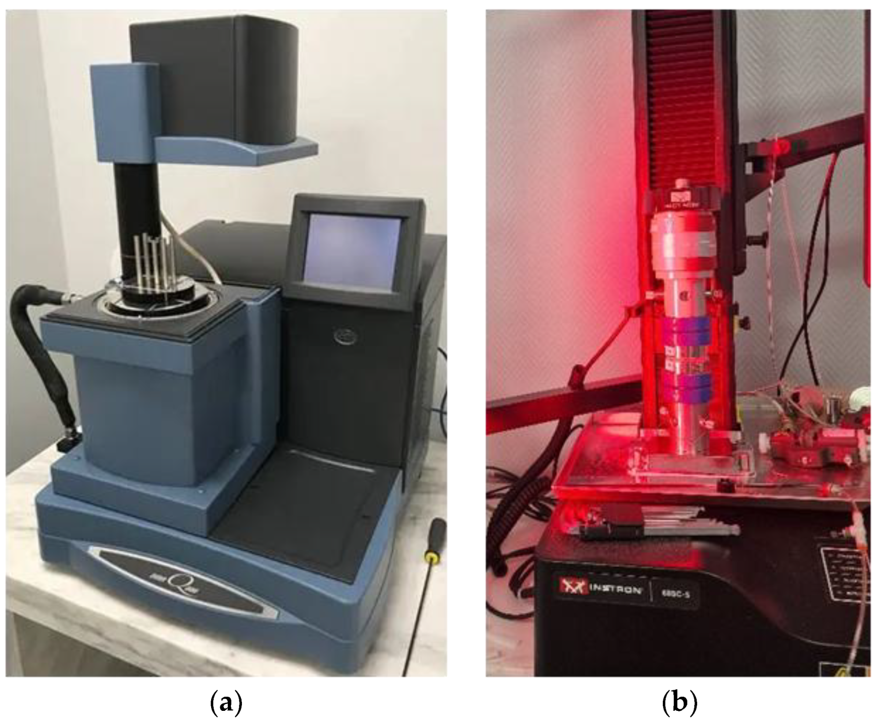
Figure 2.
Samples: a-c are rectangular for DMA; d-f are cylindrical for USS and TEC.
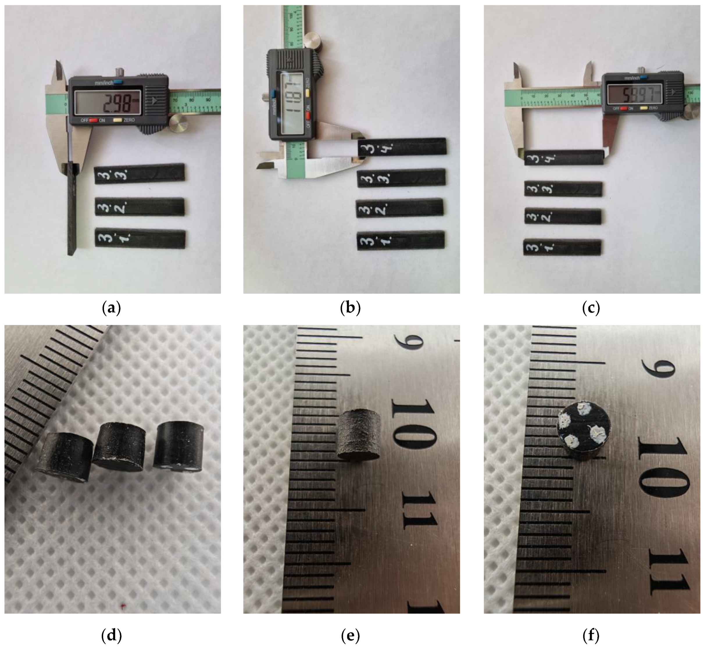
Figure 3.
Phase shift angle.
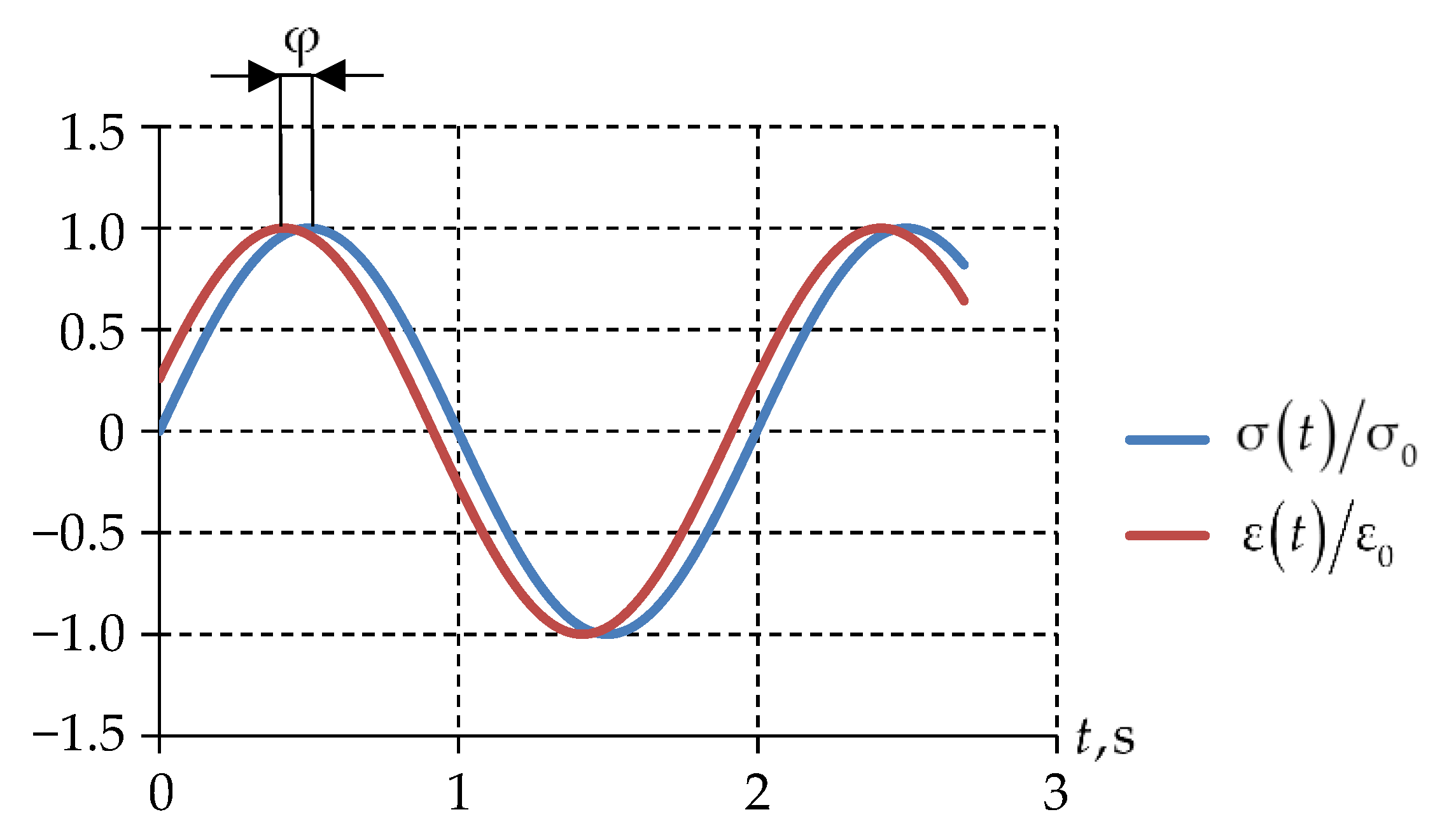
Figure 4.
Computational scheme of the spherical bridge bearing: 1 and 2 are top and bottom steel plates, correspondingly; 3 is polymer sliding layer.
Figure 4.
Computational scheme of the spherical bridge bearing: 1 and 2 are top and bottom steel plates, correspondingly; 3 is polymer sliding layer.
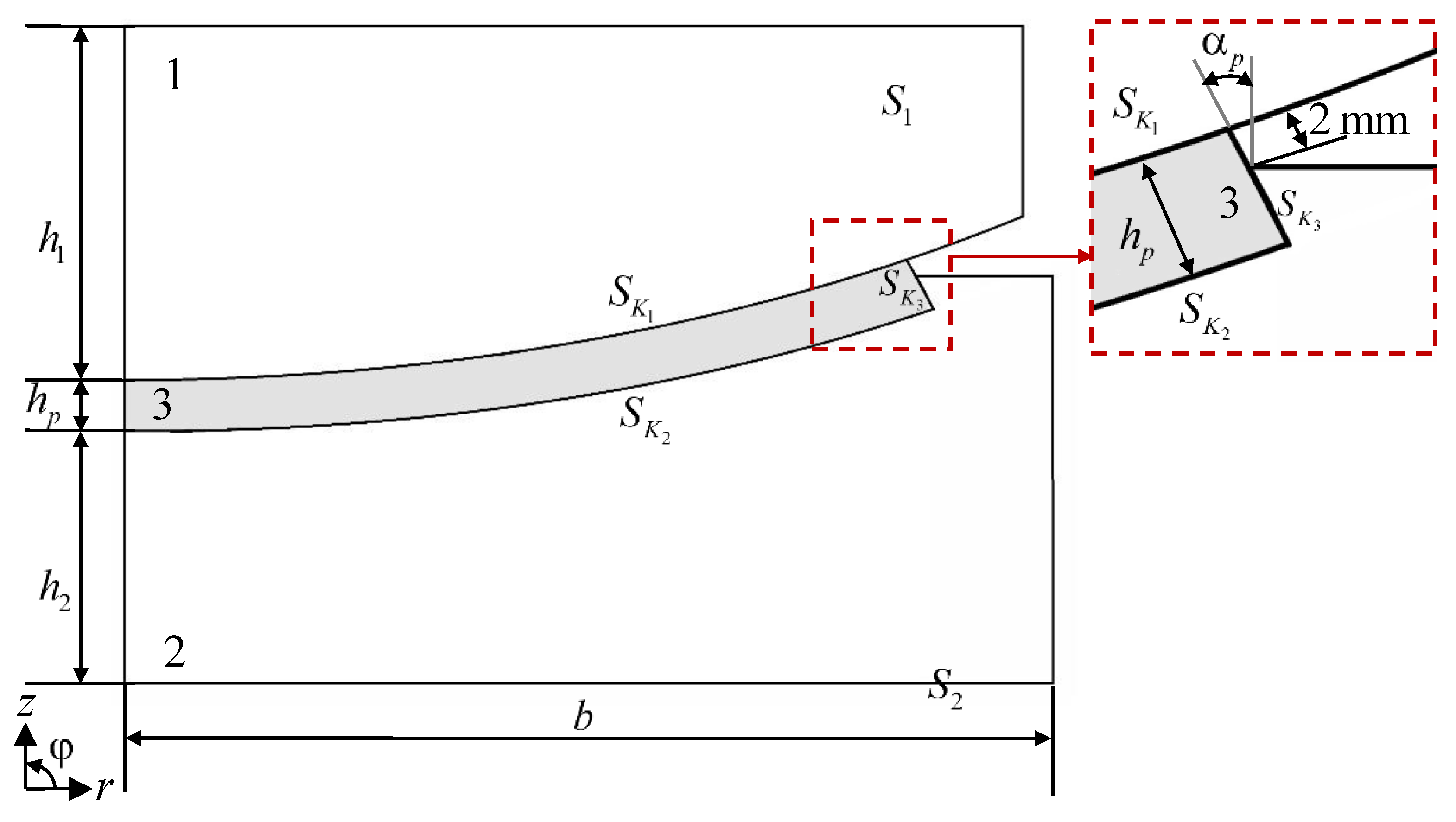
Figure 5.
Loading diagram of a spherical bridge bearing: on the right, a red rectangular area is shown enlarged, demonstrating one loading cycle.
Figure 5.
Loading diagram of a spherical bridge bearing: on the right, a red rectangular area is shown enlarged, demonstrating one loading cycle.
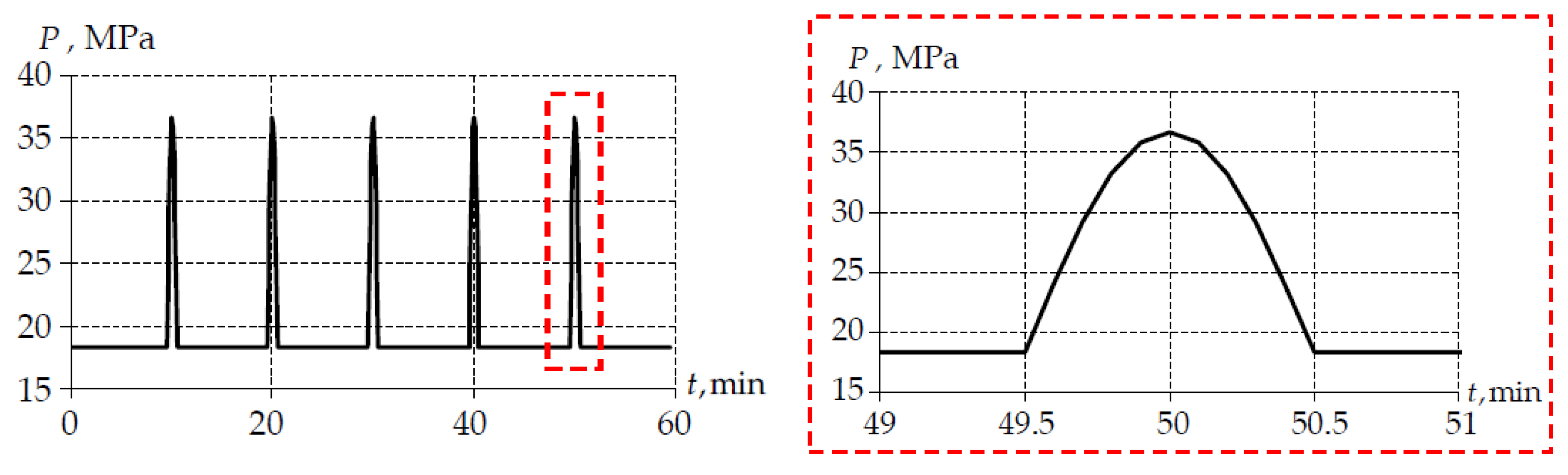
Figure 6.
Temperature dependences of the storage modulus, loss modulus, and the loss angle tangent of UHMWPE.
Figure 6.
Temperature dependences of the storage modulus, loss modulus, and the loss angle tangent of UHMWPE.
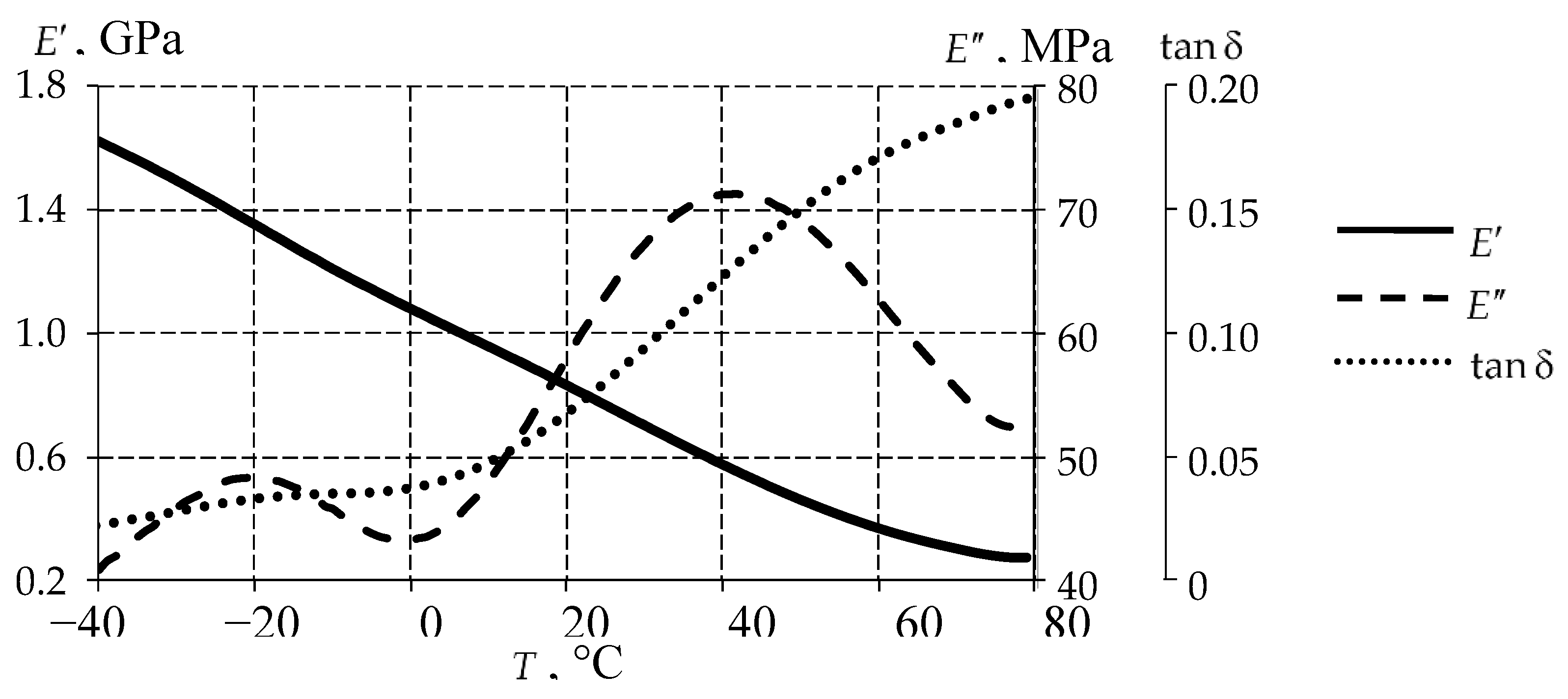
Figure 7.
Cylindrical specimens: a is before straining; b, c are after straining at different angles.
Figure 7.
Cylindrical specimens: a is before straining; b, c are after straining at different angles.
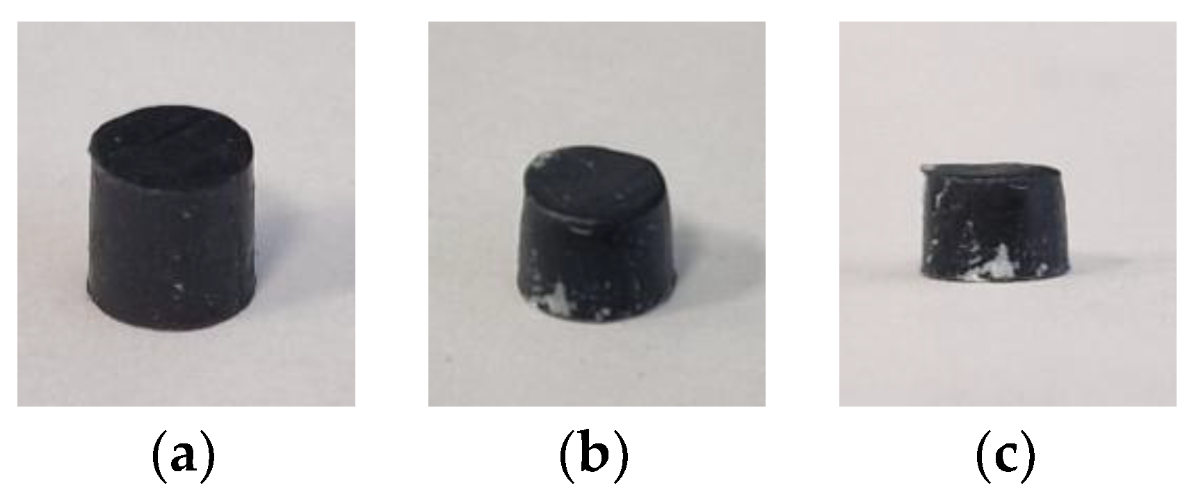
Figure 8.
The elastic modulus and the Poisson ratio dependencies on temperature, obtained in the series of USS tests: dots is averaged data; solid line is approximation.
Figure 8.
The elastic modulus and the Poisson ratio dependencies on temperature, obtained in the series of USS tests: dots is averaged data; solid line is approximation.
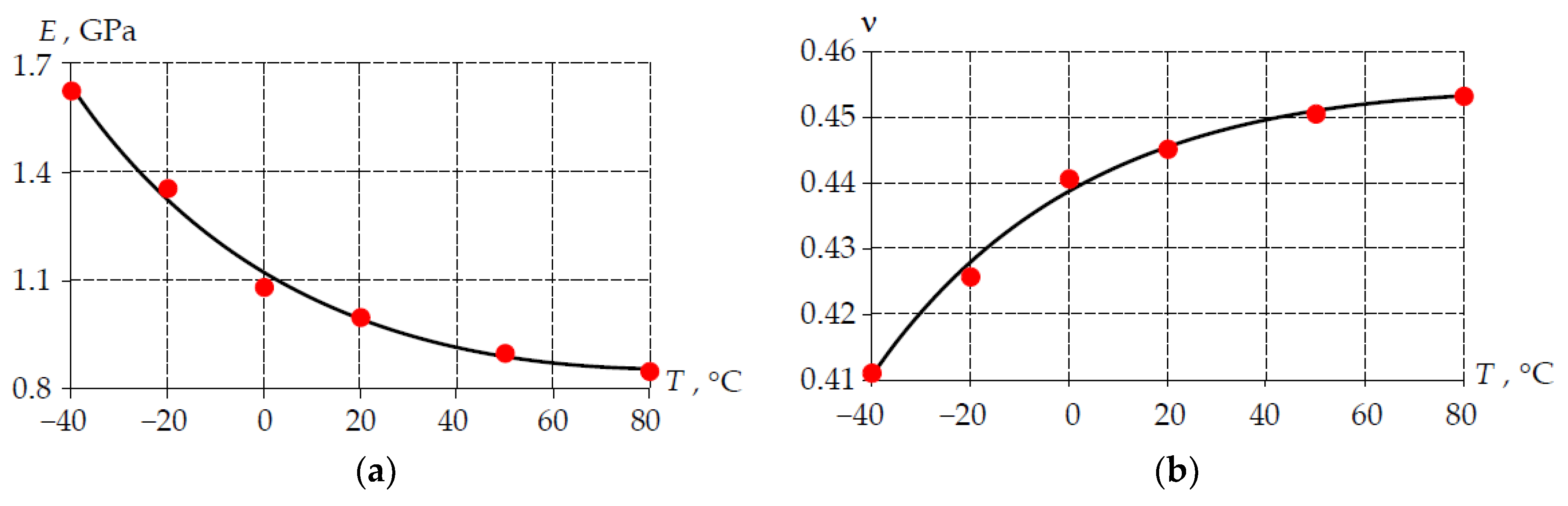
Figure 9.
Relative shear modules distribution depending on relaxation time.
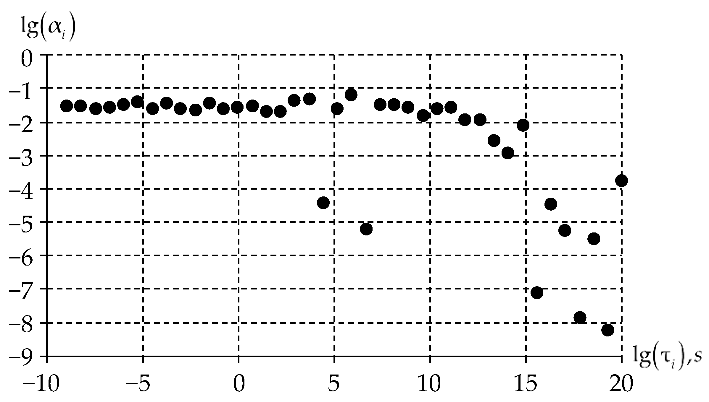
Figure 10.
Yield strength initial value dependence on temperature.
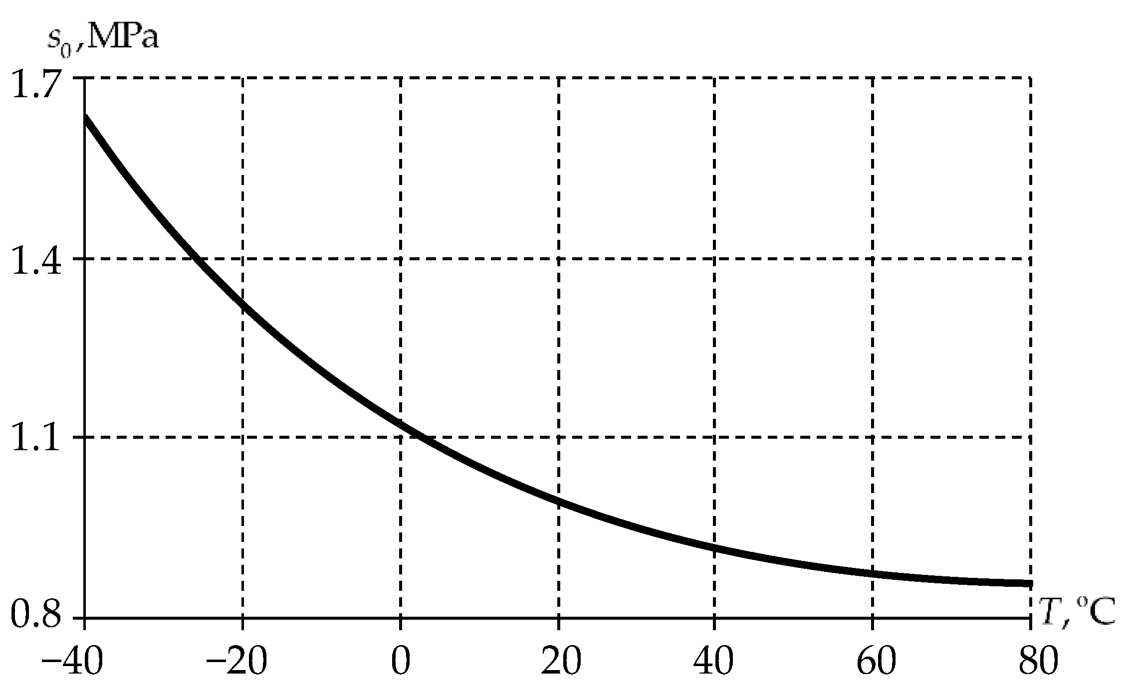
Figure 11.
Activation energy dependence on temperature.
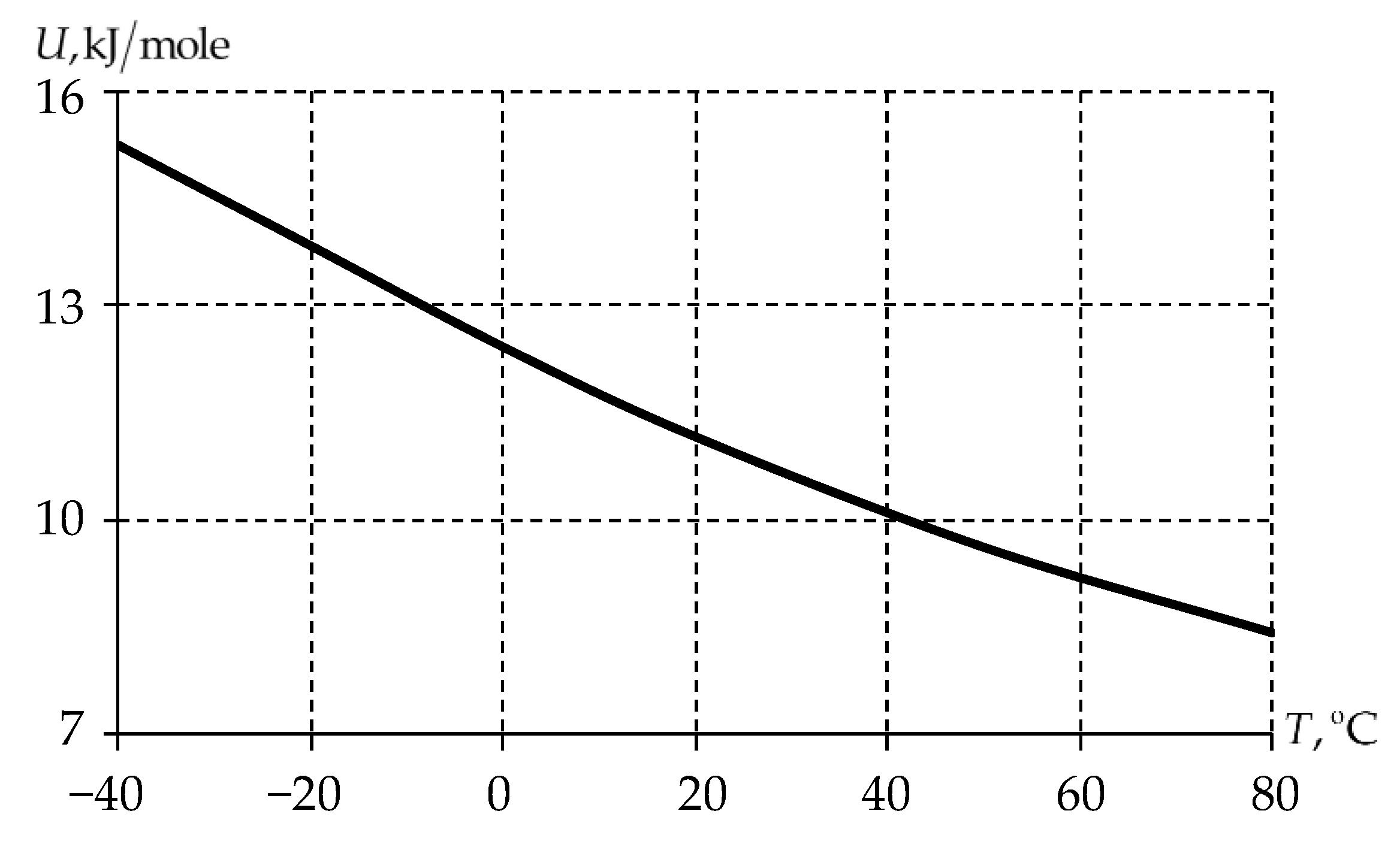
Figure 12.
Temperature dependence of the strain rate sensitivity factor.
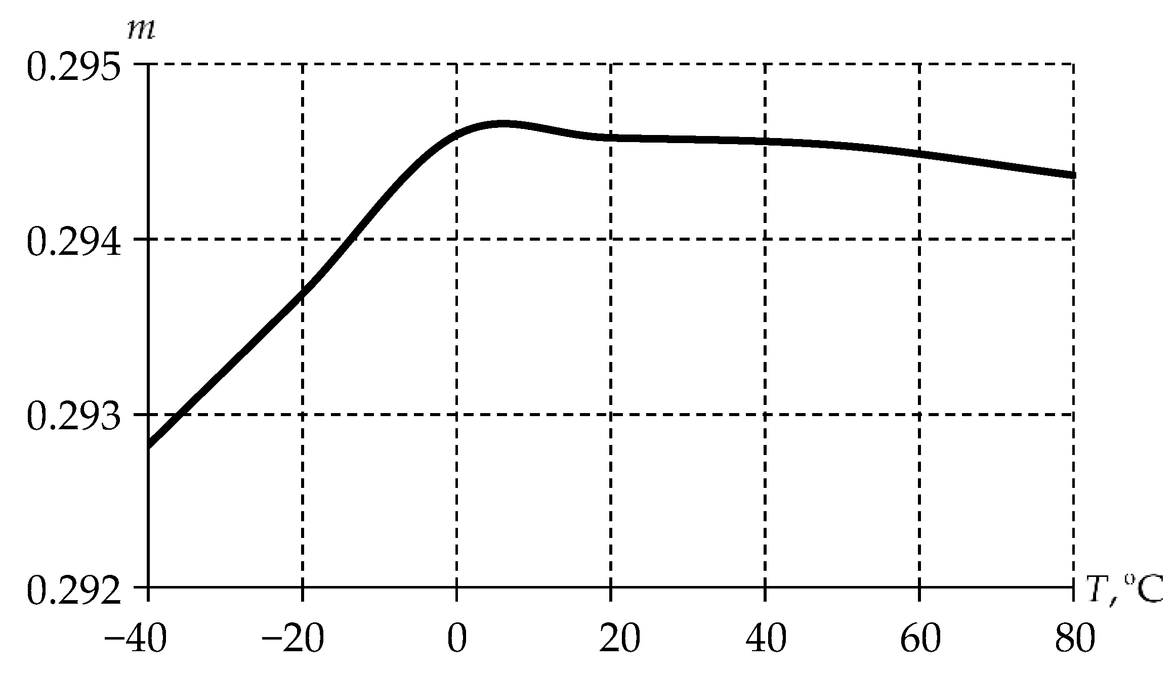
Figure 13.
Bridge bearing settlement dependence on the number of loading cycles: solid line is elastic-viscoplastic model; dashed line is viscoelastic model.
Figure 13.
Bridge bearing settlement dependence on the number of loading cycles: solid line is elastic-viscoplastic model; dashed line is viscoelastic model.
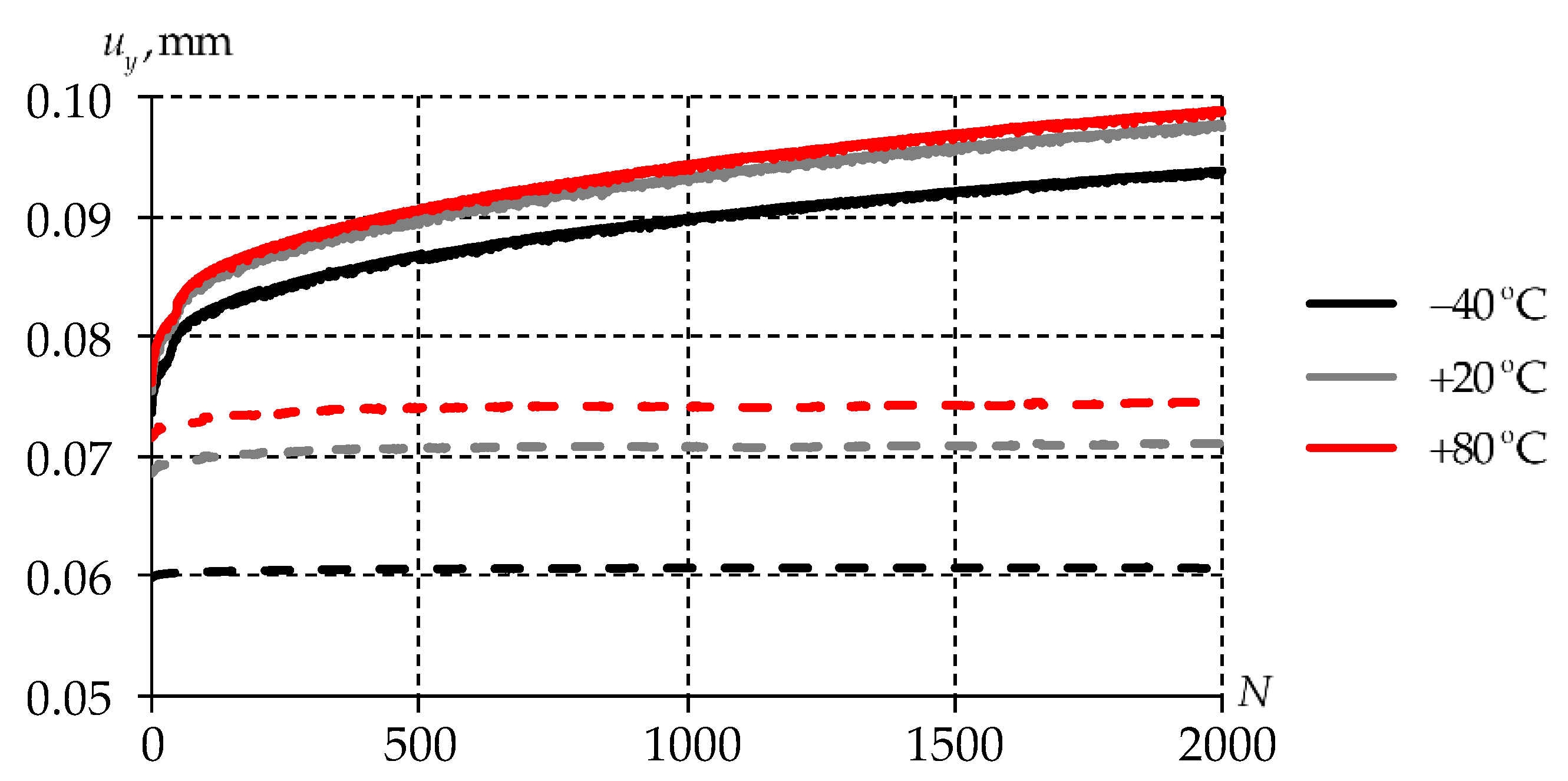
Figure 14.
Dependence of the maximum displacement level of the end face of the antifriction layer
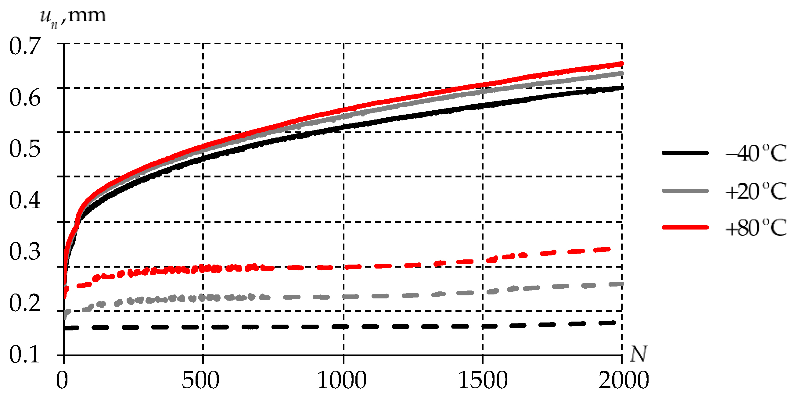
Figure 15.
Dependence of the maximum plastic deformation values of the antifriction layer on the number of loading cycles: solid line is elastic-viscoplastic model; dashed line is viscoelastic model.
Figure 15.
Dependence of the maximum plastic deformation values of the antifriction layer on the number of loading cycles: solid line is elastic-viscoplastic model; dashed line is viscoelastic model.
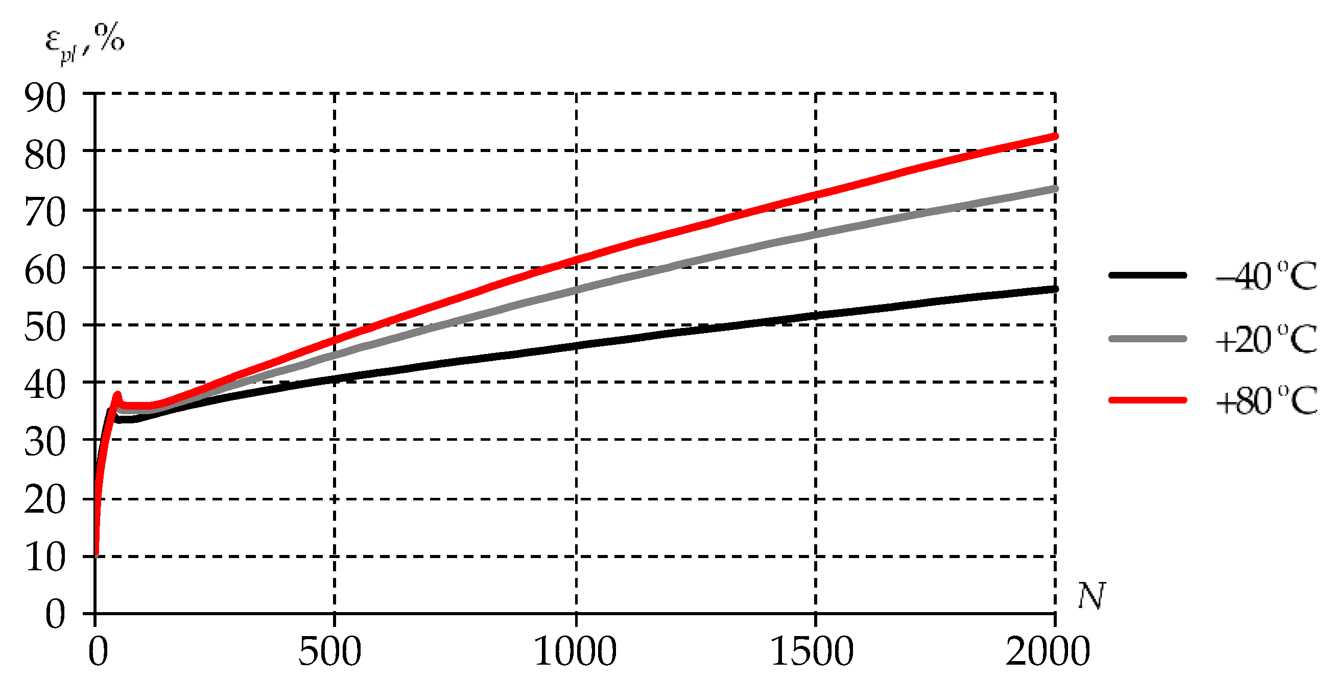
Figure 16.
Plastic deformations of the antifriction layer after 2000 loading cycles: red oval is the area near the layer end face with a stress concentrator; violet-colored oval is the area of the maximum plastic deformation level (stress concentrator); black rectangular area is simplified diagram of the bridge bearing near the end face of the layer.
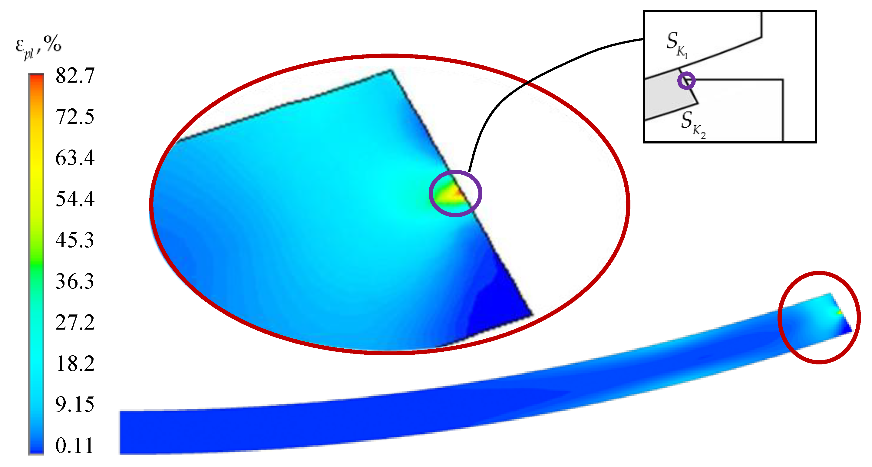
Figure 17.
Dependence of the maximum plastic deformation values of the antifriction layer on the number of loading cycles: solid line is elastic-viscoplastic model; dashed line is viscoelastic model.
Figure 17.
Dependence of the maximum plastic deformation values of the antifriction layer on the number of loading cycles: solid line is elastic-viscoplastic model; dashed line is viscoelastic model.
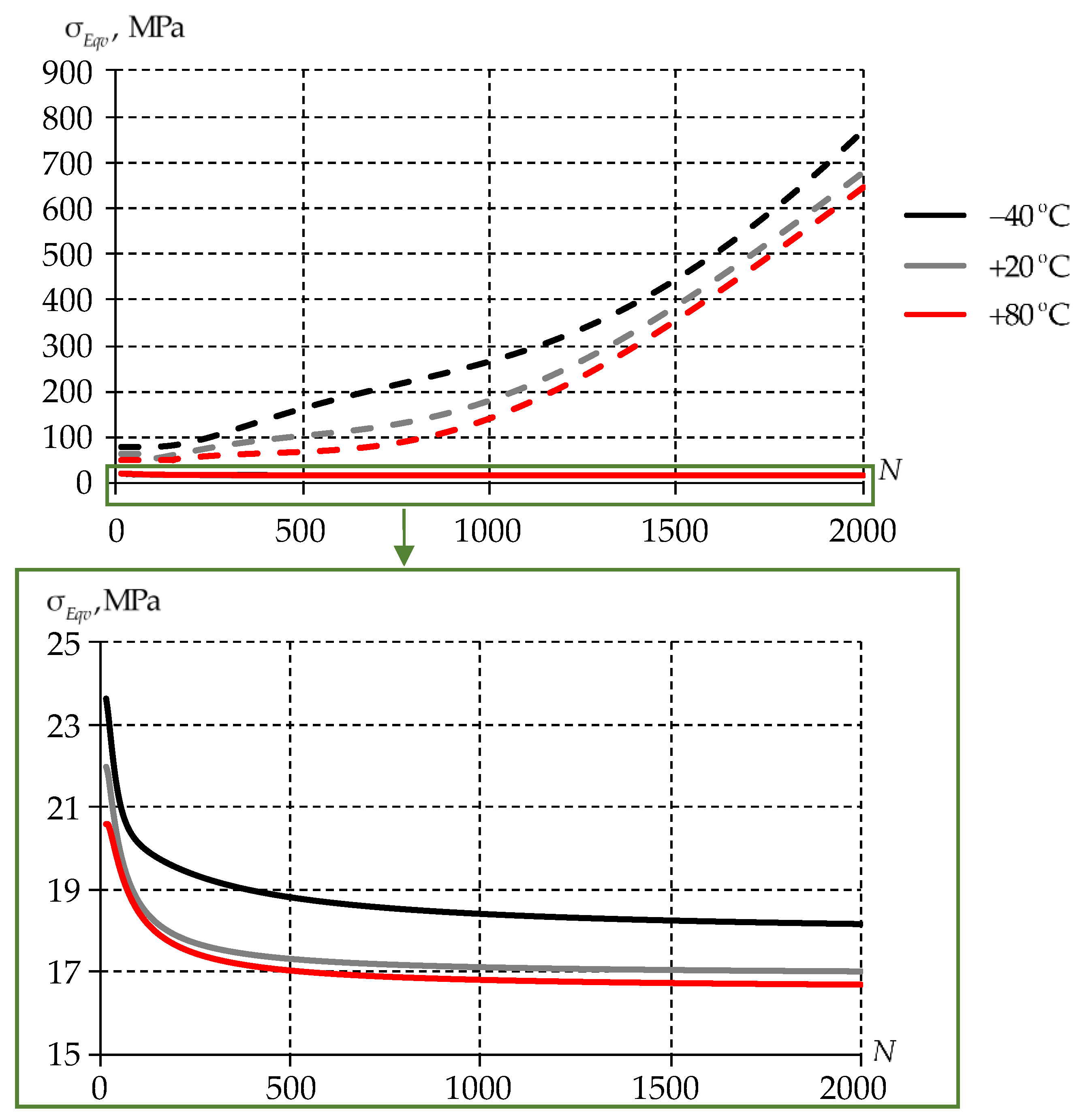

Table 1.
Empirical constants for description .
| Empirical constants | , MPa | , K | , K | ||
|---|---|---|---|---|---|
| Value | 2048 | −1355 |
Table 2.
Empirical constants for description .
| Empirical constants | , K | , K | |||
|---|---|---|---|---|---|
| Value | 0.00016 | -0.95978 | 5.912088 | 61666.38 | 229.2025 |
Disclaimer/Publisher’s Note: The statements, opinions and data contained in all publications are solely those of the individual author(s) and contributor(s) and not of MDPI and/or the editor(s). MDPI and/or the editor(s) disclaim responsibility for any injury to people or property resulting from any ideas, methods, instructions or products referred to in the content. |
© 2025 by the authors. Licensee MDPI, Basel, Switzerland. This article is an open access article distributed under the terms and conditions of the Creative Commons Attribution (CC BY) license (http://creativecommons.org/licenses/by/4.0/).
Copyright: This open access article is published under a Creative Commons CC BY 4.0 license, which permit the free download, distribution, and reuse, provided that the author and preprint are cited in any reuse.


