
Submitted:
03 November 2025
Posted:
04 November 2025
You are already at the latest version
Abstract
Neck pain due to traumas, amyotrophic lateral sclerosis (ALS), head neck cancer (HNC) are only some of the possible issues requiring a suitable therapy for alleviating or, even, healing the neck dysfunctions they cause. Static and dynamic neck braces are commonly employed in therapies for neck recovery and in the measurements necessary to quantify neck impairment or to set up a suitable therapy. Serial and parallel mechanisms, among others, have been proposed as possible neck braces. Here, a novel single-loop spherical mechanism is proposed as possible neck brace. Its kinematics and mobility analyses are presented with reference to the specific application in a neck brace. Then, its dimensional synthesis with neck brace’s kinematic requirements is addressed till to compute the geometric constants that guarantee an orientation workspace similar to the one of the human neck. The presented analyses and syntheses show that the new proposal is effective and can solve some concerns of the already proposed mechanisms for neck braces.
Keywords:
neck rehabilitation
; neck brace
; spherical mechanism
; kinematics analysis
; dimensional synthesis
1. Introduction
Neck dysfunctions come from musculoskeletal disorders and/or neurologic issues caused by diseases (e.g., amyotrophic lateral sclerosis (ALS) [1], head neck cancer (HNC) [2]) or accidents (e.g., whiplash due to impacts [3]). Most of these causes yield neck pain [4] and reduction in the range of motion (ROM) of the cervical spine (i.e., of the relative motion between head and shoulders) since it ultimately leads the patient to reduce neck’s ROM to avoid pain. Neck pain globally affected 203 million people [5] in 2020 (i.e., 2450 people per 100,000 population) with high social cost [6] due to absence at work and to health care. These data make neck pain one of the most common musculoskeletal disorders.
Mechanical action on the patient’s neck, implemented through neck braces [3], is one of the physical therapies that is often necessary to either alleviate or, even, heal neck dysfunctions. Indeed [4,7], immobilization or stretching or passive mobilization of the neck yield benefits in many cases. Neck braces are also employed in the measurements [8,9] necessary to quantify neck impairment or to set up a suitable therapy.
Static and dynamic neck braces have been proposed for neck therapies. Static neck braces are mainly collars that allow the immobilization of the neck at a fixed posture [3,10] to match the needs of cervical-spine-injury (CSI) healing and of post cervical spine surgery [11]. Instead, dynamic neck braces are mechanisms that allow a guided relative motion between head and shoulders and, in general, can implement any type of neck’s physical therapy.
Serial [9,12,13] and parallel mechanisms [8,14,15,16,17,18,19,20] have been proposed as neck braces both for wearable assistive devices (WAD) and for outpatient therapies. Such mechanisms connect a frame, fixed either to the patient shoulders (e.g., through a vest) or to a seat the patient is seating on, to a distal link (end effector), fixed to the patient head (e.g., through a harness surrounding the forehead (i.e., frontal, parietal and occipital bones) or a chin carrier suitably connected to the head back). In serial (parallel) mechanisms, one kinematic chain (a number of kinematic chains (limbs)) with links connected in series joins (simultaneously join) these two ending links. In general, serial mechanisms (SMs) allow a ROM wider than parallel mechanisms’ (PMs) one, but they are less precise and stiff than PMs. In terms of kinetostatic performances, a good compromise might be a PM with a reduced number of limbs.
The natural motion that the neck allows to the head with respect to the shoulders is a spatial motion with six degrees of freedom (DOF) where the three translational DOFs have much limited ROMs and the three rotational DOFs have large ROMs [21,22]. Consequently, it can be approximately mimicked by a 3-DOF spherical or quasi-spherical motion [23]. Accordingly, dynamic neck braces with less than three DOFs [13,19] perform only specific tasks; whereas, those with three [8,12,16,17,20] or more (up to 6) [9,14,15] are general purpose, conceived to implement any task.
A reduced number of DOFs facilitate the design of PMs with a reduced number of limbs since having only one actuated pair per limb, located on the frame, is a common choice during design. Consequently, in the literature, neck braces based on PM types with 3 DOFs (3RRS [8], 3RPS [16,17], 3RXS [20] (Here, the number indicates the number of limbs. The string of characters indicates the limb type. R, P, S and X denote revolute, prismatic, spherical and compliant X-shaped pairs, respectively. The sequence of characters in the string indicates the sequence of joint types encountered in the limb when moving from the frame to the distal link.)) are much more than those with 6 DOFs (6SPS with 6-3 [14] and 6-6 [15] limb arrangement). The limb number is further reducible to two by adopting 3-DOF single-loop architectures with two actuated joints on the frame and the third one near to the frame. Here, the use of these types of architectures as neck braces is investigated and a novel type of dynamic neck brace is proposed together with its kinematic analysis and dimensional synthesis. The proposed neck brace can be sized to generate both spherical and quasi-spherical motion since it is based on a non-overconstrained single-loop 3-DOF spatial architecture.
This paper is organized as follows. Section 2 provides the necessary background materials, identifies the design requirements of a general purpose dynamic neck brace and presents the architecture of the novel dynamic neck brace together with its kinematic and singularity analyses. Then, section 3 uses the relationships deduced in the previous section to address the dimensional synthesis of the proposed orthosis and the workspace analysis of the so-sized mechanism. Eventually, section 4 discusses the obtained results and section 5 draws the conclusions.
2. Materials and Methods
The analysis of neck’s natural motion is central for the definition of the design requirements of a dynamic neck brace. In this section, firstly, neck biomechanics is briefly recalled to identify these requirements. Then, the selection of the proposed single-loop architecture is discussed with reference to the literature on dynamic neck braces and on spherical 3-DOF non-overconstrained PMs. Eventually, the kinematics of the proposed mechanism is studied to deduce all the relationships necessary to size it according to given motion requirements.
2.1. Summary of Neck Biomechanics and Identification of Neck Braces’ Requirements
The kinematic constraint that the neck imposes to the relative motion between head and shoulders in healthy and neck-injured people has been addressed in many papers (see, for instance, [24,25,26,27]) and textbooks (see, for instance, [21,22]).
The head displacements are measured by taking as pose reference the standard anatomical position (see chapter 1.4A of Ref. [28]), also named Frankfurt plane, hereafter, referred to as neutral position. The neutral position of the head (Figure 1(b)) is the one assumed by the skull when the subject is standing upright and looking straight ahead (Figure 1(a)) with the orbitales (eye sockets), lower margins of the orbits, and the poria (ear canal upper margins) all lying on the same horizontal plane, which is parallel to the transverse plane (see Figure 1(a)). At this pose, the introduction of two coincident Cartesian reference systems (see Figure 1(b)), one fixed to the skull and the other fixed to the shoulders, with the xz-coordinate plane coincident with the sagittal plane (see Figure 1(a)) and the coordinate planes xy and yz parallel to the transverse and the coronal plane, respectively, makes it possible to define the following head displacements:
- counterclockwise rotation around the x-axis, named Right(+)/Left(-) Lateral Bending,
- translation along the x-axis, named Protraction(+)/Retraction(-),
- counterclockwise rotation around the y-axis, named Flexion(+)/Extension(-),
- translation along the y-axis, named Left(+)/Right(-) translation,
- counterclockwise rotation around the z-axis, named Left(+)/Right(-) Axial Rotation,
- translation along the z-axis, named Upward(+)/Downward(-) translation.
From a mechanical point of view, the cervical spine consists of seven links (see Figure 1(b)), the vertebrae C1 (atlas), C2 (axis), C3, …, C7, that connect the occipital bone (O) of the skull to the first vertebra, T1, of the thoracic spine. The intervertebral joints O-C1 and C1-C2 have a structure that is different from the remaining joints. Nevertheless, in general, all the intervertebral joints can be considered as spherical pairs with a limited mobility that, in the O-C1, is very limited in all the coordinate planes and, in the C1-C2, is much larger in the horizontal plane (axial rotation). Consequently, the DOF number of the cervical spine is higher than six. Even though the cervical spine is a redundant spatial kinematic chain, the limited ROM of each intervertebral joint makes the translation of the skull with respect to the shoulders an unnatural motion, limited to few centimeters along the x axis [29] and negligible along the y and z axis, which, in practice, reduces the actual DOF number mainly to the three rotations. Mechanisms that try to replicate the kinematic structure of the cervical spine have been presented in the literature (see, for instance, [30,31]).
The fact that rotations are prevalent in neck motion has lead to characterize the head mobility by evaluating only these three rotations with different measurement techniques [32]. About all the reported measurements consider these three movements as independent planar motions occurring in the three coordinate planes, (i.e., sagittal, horizontal and coronal planes for flexion/extension, axial rotation and lateral bending, respectively) and give their extreme values when performed starting from the neutral position. Table 1 summarizes these values as presented in [21] and Table 2 provides the contribution to the ROM due to each intervertebral joint as presented in [22]. These values suggest the adoption of the values reported in Table 3 for the ROM of a dynamic neck brace that has to match the motion needs of about all the possible patients. Also, if a 3-DOF spherical/quasi-spherical mechanism is adopted, the fact that the neck anatomy allows very limited translations leads the designer to impose that the spherical motion center (SMC) of the brace be located on the cervical spine more or less in the middle (i.e., at the level of vertebra C4 (see Figure 1(b))). Indeed, this choice minimizes the relative translation between two adjacent vertebrae that occurs when the patient neck has to follow the motion imposed by the dynamic neck brace. The best position of the SMC could be also determined through self-alignment techniques similar to the ones presented in [33,34], when the patient starts wearing the brace, by making the patient move the head with the brace that follows the movements with the calibration joints unlocked. Below, section 4 discusses how to locate the SMC more in depth.
2.2. The RRU-RRS Mechanism
From an architectural point of view, as explained above, a 3-DOF spherical, non-overconstrained, single-loop mechanism is a good compromise that may join structural simplicity with good stiffness, ample-enough workspace and possibility of having also quasi-spherical motion. The type synthesis of spherical 3-DOF mechanisms has been addressed in the literature [35,36,37,38,39] and single-loop architectures have been identified.
The Chebychev–Grübler–Kutzbach criterion and Euler’s formula [40,41] applied to single-loop mechanisms yield:
where l is mechanism’s DOF number, n is the link number, ci is the number of joints with i DOF and f is the DOF number of the free rigid body, which is equal to 6 for spatial motion and to 3 for spherical motion. A single-loop spherical mechanism, that is, with l≥1 for f=3 in Eq. (1), is overconstrained, if Eq. (1) gives l≤0 for f=6, and non-overconstrained otherwise. This means that, if the geometric conditions that impose the spherical motion of all the links are not satisfied, overconstrained mechanisms become isostatic (l=0) or hyperstatic (l<0) structures and jam, whereas non-overconstrained ones remains hypostatic (l≥1) structures and keep moving with a spatial quasi-spherical motion. Consequently, a single-loop 3-DOF neck brace needs a spherical non-overconstrained architecture that has l=3 for f=6 in Eq. (1) to make the distal link perform both spherical and quasi-spherical motion. Moreover, in such a mechanism, each of the two limbs simultaneously connecting frame and distal link must have a connectivity not-less than 3 where, by extension from [42], the limb connectivity is defined as the DOF number that the distal link would have, with respect to the frame, if it was connected to the frame only by that limb. Indeed, the DOF number of the relative motion between distal link and frame cannot be higher than the minimum value of the connectivity of the limbs.
By keeping in mind all the above-reported reminders, the 3-DOF spherical, non-overconstrained, single-loop architecture proposed here was identified by starting from a spherical architecture of type RRR-RRS (Figure 2(a)), where all the R-pair axes share a common intersection point (point C in Figure 2(a)). Having a common intersection point shared by all the R-pair axes is the geometric condition that imposes the spherical motion with this point as SMC to all the links. This particular RRR-RRS architecture consists of two limbs, one of type RRR and the other of type RRS, that simultaneously connect the distal link to the frame. The RRR limb, which has connectivity three, makes the distal link perform only spherical motion with respect to the frame, since the axes of its three R pairs share a common point. Differently, the RRS limb, which has connectivity five, only limits/controls the spherical motion imposed by the RRR limb. For this architecture, Eq. (1) gives 5 DOFs for f=3, but only three DOFs are possible for the distal link due to the RRR limb (i.e., the remaining two DOFs are idle and could be eliminated by replacing the S pair with another R pair whose axis passes through the SMC), but, unfortunately, only 2 DOFs for f=6. Therefore, if the geometric condition that guarantees the spherical motion is violated, this mechanism will perform a quasi-spherical motion with only two DOFs, which are not sufficient for its application in a neck brace. This problem is solvable by adding an idle R pair at the ending, adjacent to the distal link, of the RRR limb whose axis is perpendicular to the axis of the third R pair of this limb (Figure 2(b)). The resulting new architecture is of type RRU-RRS (Figure 2(b)), where U stands for universal joint. The U joint of the RRU limb is constituted by two mutually orthogonal R pairs: the first one, not adjacent to the distal link, with axis passing through the SMC of the old RRR limb and the second one adjacent to the distal link. For this new mechanism, the following statement gives the geometric condition that guarantees the spherical motion of all the links.
Statement: In a RRU-RRS mechanism, if, out of singularities, the axes of the first three R pairs of the RRU limb and of the two R pairs of the RRS limb share a common intersection point, all the links are constrained to perform a spherical motion with this common intersection point as SMC.
The proof of this statement is as follows.
Proof: In the RRU limb, the two links that joins the three joints of this limb and the cross link of the U joint (link 4 in Figure 2(b)), when manufactured and assembled so that the axes of the first three R pairs share a common intersection point, physically keep this sharing hold during motion. Therefore, they are physically constrained to perform a spherical motion with this shared point as SMC, hereafter named SMCRRU, and the center of the U joint (point CU in Figure 2(b)), which is the intersection point of the axes of the two mutually orthogonal R pairs constituting the U joint, must always move on a sphere centered at SMCRRU.
Moreover, in the RRS limb, if the link that joins the two R pairs is so manufactured that the axes of these two R pairs share a common intersection point, it physically keeps this sharing hold during motion. Therefore, the two links that join the three joints of this other limb are physically constrained to perform a spherical motion with this intersection point as SMC, hereafter named SMCRRS, which constrains the center of the S joint (point CS in Figure 2(b)) to move on a sphere centered at SMCRRS.
If such RRU and RRS limbs are assembled in a RRU-RRS mechanism so that SMCRRU coincides with SMCRRS, five of the six mobile links of the mechanism must perform a spherical motion with the same SMC and the two points CU and CS must move on concentric spheres that have this SMC as center. Therefore, under this condition, if also the distal link, which is the sixth mobile link, performs a spherical motion with the same SMC, the proof of the above statement is complete.
Such a demonstration can be given as follows. The two points CU and CS are points at rest with respect to the distal link and are considerable as belonging to the distal link together with the segment CUCS, which, due to the particular motion of these two points, can only perform a spherical motion with the same SMC as the other five mobile links. Moreover, the U joint forbid the rotation of the distal link around axes that do not lie on the plane passing through CU and is parallel to its R-pair axes. Therefore, provided that point CS does not lie on this plane, which is a particular geometric condition that can be avoided by suitably sizing the links (i.e., it is a structural singularity), the distal link cannot rotate around the segment CUCS. Since such a rotation is the only motion that would make the distal link perform a non spherical motion around the same SMC as the other links, the conclusion is that even the distal link must perform such a spherical motion. Q.E.D.
The so-deduced spherical RRU-RRS is also obtainable from the spherical non-overconstrained architecture of type 3RRS proposed in [43], which was used in [8] to obtain a quasi-spherical neck brace, by eliminating one RRS limb and, successively, replacing one S pair with one U joint in one out of the two remaining RRS limbs. The 3RRS neck brace proposed in [8] has been employed for measurements [44] and rehabilitation therapies [45,46,47]. It has a wide workspace that covers 63% of flexion/extension ROM, 65% of axial-rotation ROM and 85% of lateral-bending ROM. Therefore, the structural simplification introduced with the novel RRU-RRS architecture is prone to extend this workspace till to satisfy the design requirements of Table 3 and to satisfy better all the needs of those measurements and therapies where the 3RRS neck brace is employed.
2.3. Position Analysis of the RRU-RRS Mechanism
In the proposed RRU-RRS neck brace, for all the applications where the brace moves the patient head, fixed to the distal link, the actuated joints are the two R pairs of the RRS limb and the R pair of the RRU limb that is adjacent to the frame, which is fixed to the patient shoulders. This choice satisfies the requirement of having two actuated joints on the frame and the third one near to the frame.
The position analysis of a mechanism consists in the solution of two problems: the inverse position analysis (IPA) and the forward position analysis (FPA). The IPA is the determination of the actuated joints’ variables for an assigned pose of the output link, which here is the distal link. Conversely, the FPA is the determination of the output link’s pose(s) compatible with assigned values of the actuated joints’ variables. The solution of both these problems is necessary for designing the control system of the mechanism motion.
Figure 3 shows the notations adopted here. With reference to Figure 3, the vectors ui and the angles θi, for i=2, …, 7, are the axes’ unit vectors and the joints’ variables, respectively, of the six R pairs and their right subscript i is the number associated to the R pair they refer to. The angle θi, for i=2, …, 7, is positive if counterclockwise with respect to ui and is equal to zero when the two links joined by the i-th pair are folded on one another with the geometric elements of their ending joints (i.e., the center for an S pair and the axis for an R pair) lying on the same plane. Points C, CU and CS are the centers of the mechanism’s spherical motion (i.e., the SMC), of the U joint and of the S pair, respectively. Points C6 and C7 are the feet of the perpendiculars from point CS to the axes of R pairs 6 and 7, respectively. Points C3, C2 and C5 are the feet of the perpendiculars from points CU, C3 and C6, respectively, to the axes of R pairs 3, 2 and 5, respectively. d2, d3, d5, d6, dU, and dS are the distances of points C2, C3, C5, C6, CU and CS, respectively, from point C; whereas, d7 is a signed distance so defined that the vector relationship (CU − C7) = d7u7 holds. h2, h3, h5, h6, and h7 are the lengths of the segments C2C3, C3CU, C5C6, C6CS, and C7CS, respectively, The vectors v1 and v7 are unit vectors so defined that the vector relationships (CS − C) = dSv1 and (CS − C7) = h7v7 hold. ϕi and vi, for i=1, 2, 3, are joint variables and axes’ unit vectors, respectively, of a virtual RRR spherical kinematic chain that replaces the S pair to analytically model its kinematics. Eventually, α1, α2, α3, and α5 are the angles formed by the axes of the two R pairs at the endings of links 1, 2, 3 and 5, respectively.
With the above defined notations, the actuated-joints’ variables are θ2, θ5 and θ6, and the following relationships among geometric constants hold
Equations (2a)-(2c) and Figure 3 highlight that the independent
geometric constants that fully define the mechanism geometry are only 9, that
is, the constant angles α1, α2, α3,
and α5 plus the linear
constants dU, dS, d7, h6
and h7, which allow the computations of all the remaining
constants through formulas (2a)-(2c).
Moreover, the following relationships holds (Figure 3):
where the three vectors , and (the three vectors , and ) constitute a right-handed triplet of unit vectors
fixed to the frame (to the distal link).
The vector closure equation of the RRU-RRS
single-loop mechanism is writable as follows (see Figure 3):
The dot products of Eq. (4) by , and yield the following system of three scalar
equations
where
System (5), after the introduction of formulas
(3a)-(3j), relates the three actuated joints’ variables θ2, θ5
and θ6 to the remaining
three R pairs’ variables θ3,
θ4 and θ7, which are sufficient to
compute the pose of the distal link through formulas (3e) and (3f).
2.3.1. Inverse Position Analysis (IPA)
In the studied mechanism, the IPA consists in the
determination of the values of the three-tuple (θ2,
θ5, θ6) compatible with one assigned pose of the distal
link. If the pose of the distal link is known (see Figure 3), the positions of points CU
and CS are known in a reference system fixed to the frame; also,
since point C and unit vectors and are fixed to the frame, unit vectors and are known, too, in the same reference. As a
consequence, the dot products and are known. Such products, by exploiting formulas
(3d) and (3j), are writable as follows:
Moreover, the replacement of the explicit
expressions of and given by formulas (3b) and (3h), respectively,
into formulas (3d) and (3j), respectively, yields
where vectors and , for k=0,1,2,
uniquely depend on θ3 and θ6, respectively, through the
following explicit formulas
The above-deduced Eqs. (7) and (9) allow the
closed-form solution of the IPA as follows. Firstly, Eqs. (7a) and (7b) yield
the following values for θ3
and θ6
Successively, for each value of θ3 and θ6 computed through formulas (11a) and (11b),
respectively, Eqs. (9a) and (9b) allow the computation of the corresponding
value of θ2 and θ5 through the following formulas
Formulas (11) and (12) lead to compute at most four
values of the three-tuple (θ2,
θ5, θ6). Consequently, the IPA of the studied mechanism
has at most four solutions.
2.3.2. Forward Position Analysis
In the studied mechanism, the FPA consists in the
determination of the poses of the distal link (i.e., of unit vectors and ) compatible with one assigned values of the
three-tuple (θ2, θ5, θ6).
If the angles θ2, θ5, and θ6 are known (see Figure 3), the positions of point CS and unit vectors and are known in a reference system fixed to the
frame; also, since point C and unit vectors and are fixed to the frame, unit vector is known, too, in the same reference.
Consequently, formulas (3d) and (3k) make it
possible to write the following relationship:
which can be rewritten as follows
where
Equation (14) is transformable into a quadratic
equation in t=tan(θ3/2) through the half-angle
tangent substitution, that is, the introduction of the trigonometric identities
cosθ3=(1−t2)/(1+t2)
and sinθ3=2t/(1+t2), and, then, solvable in
closed form through the formula:
which gives up-to-two values of θ3, that is, θ3,i = 2 arctan(ti) for i
= 1, 2, and through formula (3d) as
many values of and corresponding positions of point CU.
Since the position of point CS is known,
for each computed position of point CU, a corresponding vector (CS−CU) is computable and, by
introducing expression (3e) of unit vector into formulas (3f), usable to write the following
vector equation:
where the unit vectors , and constitute a right-handed triplet of unit vectors
fixed to link 3 (see Figure 3). Equation
(17) can be rewritten as follows
where and depend only on θ7
through the formulas:
By noting that the triplet of vectors, and are mutually orthogonal, Eq. (18) yields the
following solution formulas for θ4
and θ7
The conclusion is that the FPA leads to compute at
most four poses of the distal link compatible with one set of values of the
actuated joint variables (i.e., of (θ2,
θ5, θ6)). Indeed, Eq. (16) gives two values for θ3, which, when replaced into Eq.
(3d), yield as many values for and , whose introduction into Eq. (20a) gives at most
four values for θ7, to which
Eq. (20b) associates as many values of θ4.
All the FPA solutions are computable through closed-form formulas.
2.4. Instantaneous Kinematics and Singularity Analysis of the RRU-RRS Mechanism
The velocity, , of point C, when considered fixed to the
distal link, and the angular velocity, ω,
of the distal link are computable by moving from the frame to the distal link
along one or the other of the two limbs. This computation yields the following
two different analytic expressions for ω
and (see Figure 3)
Equating the so-obtained analytic expressions of ω and yields the following velocity-loop equations of
the studied mechanism
Equation (22a) is a linear and homogeneous system
of three equations in three unknowns that is writable in matrix form as follows
where the following definitions for the coefficient
matrix M and the unknowns’ vector ζ
have been introduced
If det(M)≠0,
system (23) admits only the trivial solution ζ=0, which corresponds to (see Eqs. (21a) and (21b)) and makes the distal
link perform a spherical motion with point C as SMC. Conversely, if det(M)=0, system (23) admits an infinity of
solutions for ζ, which can also
be non-null, that is, a constraint singularity [48] occurs where the distal link can exit from the
spherical motion. From an analytic point of view, the determinant of a 3×3 matrix is the mixed product of its column
vectors, which, in this case, yields the following formula:
By excluding the case in which one of the three
vectors is a null vector, a mixed product is equal to zero if and only if the
three involved vectors are all parallel to one plane. In the case under study
(see Figure 3), none of the three
involved vectors is a null vector. The two vectors and are both perpendicular to and identify a pencil of parallel planes that are
perpendicular to the line passing through points C and CS;
whereas, the remaining third vector is perpendicular to the plane of the U joint’s
cross link, which is the one located by the three points C, C7
and CU (Figure 3).
Consequently, the parallelism of these three vectors to one plane (i.e., a
constraint singularity) can occur if and only if point CS lies
on the plane of the U joint’s cross link. Such a result analytically confirms
what has been concluded, with a kinematic reasoning, in section 2.2 when
proving the there-reported statement. This geometric condition is avoidable by sizing
the mechanism so that the triangle CUCCS does not
degenerate into a segment, that is, by imposing
during the mechanism design, and by assembling the
mechanism at an configuration where point CS does not lie on the
plane of the U-joint’s cross link. Indeed, if the mechanism is assembled at a
non-singular configuration, that is, with point CS out of the plane
of the U-joint’s cross link, the distal link can only perform spherical motions
that make the triangle C7CUCS rigidly rotate
around the line passing through points C and CU, which
always keeps point CS out of the plane of the U-joint’s cross link.
Condition (26) contains only geometric constants of
the mechanism (i.e., it is a structural condition). Therefore, if the
mechanism is so sized that it satisfies inequality (26) and is assembled with
point CS out of the plane of the U-joint’s cross link, the possible
occurrence of a constraint singularity is definitely excluded and the distal
link can only perform spherical motion. This implies that ζ is always a null vector, which leads to
simplify Eq. (22b) as follows
where the following definitions have been
introduced:
Formulas (28) highlight that A and B are
3×3 matrices that depend on the
mechanism configuration. Such matrices are named Jacobians.
Equation (27)
relates the actuated-joint rates (i.e.,
,
and
), which are the
instantaneous inputs, to the remaining R-pair joint rates (i.e.,
and
(see Eq. 21b))
that are necessary to compute the angular velocity,
ω , which is the instantaneous output, and is
sufficient to identify the instantaneous spherical motion of the distal link.
It is the input-output instantaneous relationship of the studied
mechanism. Equation (27) allows the solution of two problems [49–51]: the
inverse instantaneous kinematics (IIK) problem and the forward instantaneous
kinematics (FIK) problem. The IIK problem is the determination of the
instantaneous inputs’ values (i.e., in the studied case, of
,
and ) compatible
with one assigned set of instantaneous outputs (i.e., in the studied case, of
ω or, which is the same, of and ). Vice versa,
the FIK problem is the determination of the instantaneous outputs’ values
(i.e., in the studied case, of
ω or, which
is the same, of
and
) compatible
with one assigned set of instantaneous inputs (i.e., in the studied case, of
,
and
).
The IIK and FIK solutions depend on the mechanism
configuration since matrices A and B depend on it. The mechanism
configurations that make instantaneous kinematics (IK) problems indeterminate
are the mechanism’s singularities. Such singularities are collectable
into three main groups [49]: (i) those that
make the IIK indeterminate, named serial (or type-I) singularities, (ii) those
that make the FIK indeterminate, named parallel (or type-II) singularities, and
(iii) those that make both the IK problems indeterminate, named type-III singularities.
At a serial singularity, the output link (i.e., the
distal link in the studied case) can stay at rest even though the
actuated-joint rates are different from zero, that is, it has a local reduction
of DOFs since the motion of one or more actuated joints does not affect its
motion. Since this kinematic condition identifies configurations that are at
the boundaries of the workspace, serial singularities are located at the
workspace boundaries and identifying them is one of the methods used for
determining the output-link’s workspace.
Differently, at a parallel singularity, the output
link can perform an instantaneous motion even though the actuated joints are at
rest, that is, it locally acquires further DOFs since the actuated joints are
no longer able to control its motion. Parallel singularities may be located
inside the workspace. The virtual work principle demonstrates that, at a
parallel singularity, even an infinitesimal external load applied to the output
link requires that one or more actuators must apply an infinite generalized
torque to equilibrate it. Such a static condition leads to the break down
either of some actuators or of some links. Therefore, parallel singularities
must be identified during design and avoided during functioning.
The analysis of Eq. (27) reveals that serial
singularities satisfy the analytic and geometric condition
and that parallel singularities satisfy this other
analytic and geometric condition
Condition (29) (condition (30)) is satisfied when
the involved unit vectors are coplanar.
3. Results
In this section, the above-reported kinematic analyses are used to size an RRU-RRS spherical mechanism that matches the design requirements of dynamic neck braces reported in Table 3. As stressed in the previous section, the independent geometric constants that fully define the geometry of this mechanism are nine (Figure 3): the four angles α1, α2, α3, and α5 plus the five lengths dU, dS, d7, h6 and h7. Consequently, the dimensional synthesis problem to address is the determination of the values of these nine constants that make the free-from-singularity orientation workspace of the distal link match the design requirements of Table 3.
Since the studied mechanism is spherical, distal-link’s orientation workspace keeps itself unchanged when the mechanism is scaled. Scalability is a sought-after feature when designing an orthosis since it must be adaptable to the patient size without changing its mobility. In addition, it allows normalizing the linear constants to size. Accordingly, in the studied case, the five constant lengths are replaced by their ratios to dS, that is, by dU/dS, 1=dS/dS, d7/dS, h6/dS and h7/dS. Therefore, the independent constants to determine reduce themselves to eight: the four angles α1, α2, α3, and α5 plus the four dimensionless ratios dU/dS, d7/dS, h6/dS and h7/dS.
With reference to Figures 1(b) and 3, in order to identify a symmetric brace that is also easy to wear, the following assumptions are introduced:
i) point C is located at the centroid of vertebra C4 and is the origin of the two Cartesian reference systems (Figure 1(b)), one fixed to the frame (i.e., to the shoulders of the patient) and the other fixed to the distal link (i.e., to the skull of the patient), that coincide with one another at the neutral position;
ii) in the frame (link 1), point C and the two R-pair axes fixed to the frame lie on the xy-coordinate plane of the reference system fixed to the frame with the two R-pair axes that are symmetrically located with respect to the sagittal plane (Figure 1);
iii) in the distal link, the vectors u7,
v7 and are all parallel to the xy-coordinate plane of the
reference system fixed to the distal link with the points CU
and CS that lie on the yz-coordinate plane of the same
reference system;
iv) α1=60°, α2=α5, sinα3=h6/dS,
0=d7/dS,
1=dU/dS
and v1⋅u4=cosα1.
The assumption 0=d7/dS
leads to (Figure 3),
which, when combined with the assumptions α1=60°, v1⋅u4=cosα1 and 1=dU/dS,
brings to the conclusion that h7/dS=1, that is, the triangle CCUCS
is equilateral. Such a triangle, for the assumptions (ii) and (iii), is located
on the yz-coordinate plane of the distal link and, at the neutral position, is
perpendicular to the transverse (horizontal) plane (Figure 1).
Figure 4,
shows frame (link 1) and distal link (link 7) at a generic configuration
together with the Cartesian reference systems Cxfyfzf,
fixed to the frame, and Cxdydzd, fixed
to the distal link for the mechanism sized with the above listed assumptions.
Hereafter, if, jf and kf
(id, jd and kd)
will denote the unit vectors respectively of the x, y and z coordinate axes of Cxfyfzf
(of Cxdydzd). All the above-listed
assumptions leave only the geometric constants α2
(=α5) and α3 (=arcsin(h6/dS))
to determine by imposing the design requirements of Table 3, and bring to compute the following
vector components
where the left superscripts f or d on
vector symbols denote vectors measured in the reference system fixed to the
frame or to the distal link, respectively.
The rotation matrix, fRd,
that transforms a vector, da, measured in Cxdydzd
to the same vector, fa, measured in Cxfyfzf
through the relationship fa = fRd da
has the general form
which, by introducing the Cardan angles ψ1, ψ2
and ψ3 of the ZYX
convention, yields the following explicit formula
It is easy to realize that the so-defined angles ψ1, ψ2
and ψ3 correspond
respectively to the axial rotation, the flexion/extension and the lateral
bending of the head (Figure 1(b)). With
reference to Figure 3 and Figure 4, the orientation
workspace (OW) of the distal link is definable as the set of all the rotation
matrix fRd that identify distal-link
orientations for which β1, β2 ≤α2+α3, in formulas
Since only the sum of α2 and α3
enters in formula (34), without losing generality, the further assumption α2=α3
can be adopted, which makes the limbs more symmetric and reduces the
dimensional synthesis to the determination of only one angle. Also, since, in
formula (34), β1 and β2 are the lower extreme of the
admissible range of values for α2+α3 , the dimensional synthesis
can be implemented by looking for the maximum values β1,max and β2,max
of β1 and β2, respectively, that are
necessary to satisfy all the design requirements of Table 3 and, then, by choosing α2=α3
> max(β1,max,
β2,max)/2. From an analytic
point of view (Figure 4) the following
relationships hold:
The introduction of the design requirements of Table 3 into formula (33) and of the resulting
rotation matrix fRd together with
the vector data given by Eqs. (31) into formula (35) yields the extreme values
of β1 and β2 reported in Table 4. The analysis of Table 4 reveals that the condition α2=α3
> max(β1,max,
β2,max)/2 is satisfied by
choosing α2=α3=56°.
Table 5 summarizes the values of the
geometric constants of the so-sized RRU-RRS neck brace, which satisfy all the
design requirements of Table 3.
By using GeoGebra [52,53,54,55], an animated 3D kinematic model of the neck brace, sized with the values reported in Table 5, has been built and used to check that, during motion, the singularity conditions, identified in section 2.4, do not occur inside the workspace. Such a model controls/changes the mechanism configuration by using the inverse position-analysis’ relationships determined in section 2.3.1 with the distal link orientation that is assigned by the user through the above defined angles ψ1, ψ2 and ψ3 (see formula (33) and the accompanying comments). This control algorithm is the same as the one that a controller should use to move the real neck brace during a passive mobilization program of the patient neck. The built model is indeed a kinematic digital twin of the mechanism that is usable for simulating its motion. Figure 5 shows the so-built 3D kinematic model with the distal link at the neutral position and Figure 6, Figure 7 and Figure 8 show the mechanism configurations with the distal link at the extreme poses of flexion/extension, lateral bending and axial rotation, respectively. In the supplementary materials accompanying this paper, the interested reader can find the GeoGebra program used to build the model and four videos that show the neutral position from different points of view, the axial rotation animation, the flexion/extension animation and the lateral bending animation. These three animations clearly show that the so-sized mechanism has no singularity inside its workspace.
4. Discussion
The above-reported results are summarizable as follow. The proposed new architecture is simple to control since its position-analysis problems are solvable in closed form. In addition, it is able to satisfy all the design requirements of a dynamic neck brace by providing a free-from-singularity workspace that covers the whole ROM of a human neck.
From a manufacturing point of view, the link interferences visible in Figure 5, Figure 6, Figure 7 and Figure 8 are easily eliminable by making the links lie on different concentric spherical shells. Moreover, the single-loop architecture of the proposed mechanism allows mounting links 3, 2, 1, 5 and 6 (see Figure 3) as a serial chain of binary links. This feature makes the intersection of all the R-pair axes at the SMC (point C in Figure 3) much easier to obtain, during the mechanism assembly, than it would be in a multi-loop architecture. Eventually, the fact that the proposed architecture has three DOFs when considered as a spatial mechanism (i.e., for f=6 in Eq. (1)) makes it work as a quasi-spherical mechanism if the intersection of all the R-pair axes at the SMC is not gotten during assembly.
When the mechanism works as a quasi-spherical mechanism (i.e., when the SMCs of the two limbs, named SMCRRS and SMCRRU in section 2.2, do not coincide with one another), the formulas of the IPA solution reported in section 2.3.1 still hold since their deduction does not use the coincidence of SMCRRS and SMCRRU. Conversely, those of the FPA solution reported in section 2.3.2 do not hold any longer, but the FPA still is solvable in closed form with a technique similar to the one reported in section 2.3.2. Consequently, the proposed neck brace remains easily employable even in those applications where the quasi-spherical motion of the neck is not negligible.
How to locate the brace’s SMC (point C in Figure 2, Figure 3, Figure 4, Figure 5, Figure 6, Figure 7 and Figure 8) on the patient neck need a deeper discussion. In the literature (see, for instance, [22,24,27,56,57]), the neck movements are analyzed by considering the three neck rotations mainly as three planar motions occurring in three mutually orthogonal planes. This approach leads to identify three different instantaneous axes of rotation (IAR) that are mutually orthogonal and change their positions during a finite movement of the neck. Consequently, if either these data were available or, as an alternative, the fixed axode [42] traced by the instantaneous screw axis (ISA) during the neck motion were known, the best location of the brace’s SMC would be the point that minimizes the sum of its distances from all these axes. The determination of such a point is cumbersome, unpractical and, ultimately, unnecessary for making a patient wear a neck brace. Indeed, as stressed in section 2.1, the cervical spine is a redundant spatial mechanism. Its redundant mobility makes it able to perform many different paths to move the distal link from one pose to another provided that the path keeps the joints’ motion within their ROM. This condition is certainly satisfied during a spherical motion of the distal link that has its SMC nearly coincident with the centroid of vertebra C4 (Figure 1(b)).
In order to reach this location, the neck brace must contain additional joints (alignment joints) that make the brace’s SMC (point C in Figure 3) translate in the sagittal plane by moving the brace’s frame (link 1 in Figure 3) with respect to the vest that fixes the brace to the patient shoulders. Of course, once the brace’s SMC has been correctly located all the alignment joints must be locked. Many planar kinematic chains can provide this 2-DOF translation; among these chains, maybe the double parallelogram mechanism (Figure 9 and Figure 10) is the most practical since it contains only passive R pairs, which are easy to move and lock.
The identification of the centroid of vertebra C4 on the neck patient could be done through radiographs, but the use of self-alignment techniques [33,34] is more practical to identify the best location of the brace’s SMC. In this case, such techniques consist in the implementation of the following steps:
i) the patient with shoulders and neck in the neutral position (Figure 1) wears the brace with the alignment joints unlocked and the actuated joints non-actuated (i.e., with the actuators unpowered and unlocked);
ii) the physiotherapist makes the brace’s SMC lie on the sagittal plane (Figure 1), the axes of the two R pairs adjacent to the frame (link 1 in Figure 3) parallel to the transversal plane and the motion plane of the alignment joints parallel to the sagittal plane. Then, he/she fixes the brace’s vest to the patient shoulders and the brace’s distal link (link 7 in Figure 3) to the patient forehead;
iii) the patient sequentially performs one full cycle of flexion/extension, one full cycle of axial rotation and one full cycle of lateral bending during which the values assumed by the joint variables of the alignment joints are recorded;
iv) the average values of the joint variables recorded in step (iii) are computed;
v) the physiotherapist locks the alignment joints at the values of their joint variables computed in step (iv) and, then, makes the patient repeat the three full cycle motions to check that he/she does not feel distress or pain in the neck when moving the head and whether a ROM reduction occurs when moving the head with the so-locked alignment joints.
Regarding brace’s wearability, the spherical nature of the proposed brace makes it scalable without affecting its motion and, consequently, its motion control system. Therefore, the adaptation of the brace size to the patient size is simply obtainable by providing either different brace sizes, or a brace with links whose dimensions are adjustable according to the patient size. Also, since the geometric constants that affect the brace motion are only the four angles α1, α2, α3, and α5 and the four dimensionless ratios dU/dS, d7/dS, h6/dS and h7/dS, the brace scaling is obtainable by varying dS while keeping these eight parameters unchanged. This means that, for instance, the distal link shape can be freely modified provided that d7/dS and h7/dS are kept unchanged and that similar considerations hold for all the other links. In short, designers have many parameters available to improve the brace wearability and adaptability.
5. Conclusions
The design requirements for a dynamic neck brace have been determined from the literature and a novel type of dynamic neck brace has been proposed. The proposed neck brace is based on a 3-DOF single-loop spherical mechanism that is not overconstrained.
Its kinematics and mobility analyses have been addressed. The results of these analyses are that its position analyses problems have closed-form solutions, which highly facilitate its control system design, and that it can be easily sized and assembled in a way that excludes the occurrence of constraint singularities.
Moreover, a kinematic digital twin of the so-sized brace has been built in GeoGebra for testing its actual ability of covering the whole ROM of a human neck without passing through singular configurations. The virtual experiments conducted with this digital twin proved its ability of actually doing it.
Eventually, an easy-to-implement procedure for making the patient correctly wear the brace has been presented. Such a procedure is based on self-alignment techniques and additional alignment joints
All the above listed results make the proposed neck brace employable as static and/or dynamic brace in all the neck’s rehabilitation/healing therapies without any limitations.
Supplementary Materials
The following supporting information can be downloaded at: Preprints.org, one zipped file containing the the GeoGebra programs that build the digital twins shown in Figs. 5-8 and 10, and four videos that show the neutral position (Figure 5) from different points of view, the axial rotation (Figure 8) animation, the flexion/extension (Figure 6) animation and the lateral bending (Figure 7) animation.
Funding
This research was developed at Laboratory of Mechatronics and Virtual Prototyping (LaMaViP) of Ferrara University (UNIFE) and was funded by FAR2023 UNIFE.
Institutional Review Board Statement
Not applicable.
Informed Consent Statement
Not applicable.
Data Availability Statement
The original contributions presented in this study are included in the article/supplementary material. Further inquiries can be directed to the corresponding author(s).
Conflicts of Interest
The authors declare no conflicts of interest. The funders had no role in the design of the study; in the collection, analyses, or interpretation of data; in the writing of the manuscript; or in the decision to publish the results”.
Abbreviations
The following abbreviations are used in this manuscript:
| ALS | Amyotrophic lateral sclerosis |
| HNC | Head neck cancer |
| ROM | Range of motion |
| CSI | Cervical spine injury |
| C1, …, C7 | Vertebrae of the cervical spine (see Figure 1(b)) |
| O | Occipital bone |
| WAD | Wearable assistive device |
| SM | Serial mechanism |
| PM | Parallel mechanism |
| DOF | Degree of freedom |
| P | Prismatic pair or only the adjective “prismatic” |
| R | Revolute pair or only the adjective “revolute” |
| S | Spherical pair or only the adjective “spherical” |
| U | Universal joint |
| SMC | Spherical motion center |
| IPA | Inverse position analysis |
| FPA | Forward position analysis |
| IK | Instantaneous kinematics |
| IIK | Inverse instantaneous kinematics |
| FIK | Forward instantaneous kinematics |
| OW | Orientation workspace |
| IAR | Instantaneous axis of rotation |
| ISA | Instantaneous screw axis |
References
- Longinetti, Elisa; Fang, F. Epidemiology of amyotrophic lateral sclerosis: an update of recent literature. Current Opinion in Neurology 2019, 32, 771–776. [Google Scholar] [CrossRef] [PubMed]
- Gormley, M.; Creaney, G.; Schache, A.; et al. Reviewing the epidemiology of head and neck cancer: definitions, trends and risk factors. Br. Dent. J. 2022, 233, 780–786. [Google Scholar] [CrossRef] [PubMed]
- Arockia, S.; Arockia, D; Lingampally, P. K.; Nguyen, G. M. T.; Schilberg, D. A comprehensive review of wearable assistive robotic devices used for head and neck rehabilitation. Results in Engineering 2023, 19, 101306. [Google Scholar] [CrossRef]
- Prablek, M.; Gadot, R.; Xu, D. S.; Ropper, A. E. Neck Pain: Differential Diagnosis and Management. Neurol. Clin. 2023, 41, 77–85. [Google Scholar] [CrossRef]
- GBD 2021 Neck Pain Collaborators. Global, regional, and national burden of neck pain, 1990-2020, and projections to 2050: a systematic analysis of the Global Burden of Disease Study 2021. Lancet Rheumatol. 2024, 6, e142–e155. [Google Scholar] [CrossRef]
- Kazeminasab, S.; Nejadghaderi, S.A.; Amiri, P.; et al. Neck pain: global epidemiology, trends and risk factors. BMC Musculoskelet. Disord. 2022, 23, 26. [Google Scholar] [CrossRef]
- Rodriguez, A. M.; Komar, A.; Ringash, J; et al. A scoping review of rehabilitation interventions for survivors of head and neck cancer. Disabil. Rehabil. 2019, 41, 2093–2107. [Google Scholar] [CrossRef]
- Zhang, H.; Agrawal, S. K. Kinematic Design of a Dynamic Brace for Measurement of Head/Neck Motion. IEEE Robotics and Automation Letters 2017, 2, 1428–1435. [Google Scholar] [CrossRef]
- Chang, B. C.; Zhang, H.; Long. S.; Obayemi, A.; Troob, S. H.; Agrawal, S. K. A novel neck brace to characterize neck mobility impairments following neck dissection in head and neck cancer patients. Wearable Technol. 2021, 2, e8. [Google Scholar] [CrossRef]
- Johnson, R. M.; Hart, D. L.; Simmons, E. F.; Ramsby, G. R.; Southwick, W. O. Cervical orthoses. A study comparing their effectiveness in restricting cervical motion in normal subjects. The Journal of Bone & Joint Surgery 1977, 59, 332–339. [Google Scholar]
- McKeon, J. F.; Alvarez, P. M.; Castaneda, D. M.; Emili, U.; Kirven, J.; Belmonte, A. D.; Singh, V. Cervical Collar Use Following Cervical Spine Surgery: A Systematic Review. JBJS Reviews 2024, 12, e24. [Google Scholar] [CrossRef]
- Shoaib, M.; Lai, C. Y.; Bab-Hadiashar, A. A Novel Design of Cable-Driven Neck Rehabilitation Robot (CarNeck). In: Procs. of 2019 IEEE/ASME International Conference on Advanced Intelligent Mechatronics (AIM), Hong Kong, China, 2019, pp. [CrossRef]
- Mahmood, M. N.; Tabasi, A.; Kingma, I; van Dieën, J. H. A novel passive neck orthosis for patients with degenerative muscle diseases: Development & evaluation. Journal of Electromyography and Kinesiology 2021, 57, 102515. [Google Scholar] [CrossRef]
- Wu, D.; Wang, L.; Li, P. A 6-DOF exoskeleton for head and neck motion assist with parallel manipulator and sEMG based control. In Procs. of 2016 International Conference on Control, Decision and Information Technologies (CoDIT), Saint Julian's, Malta, 2016, pp. [CrossRef]
- Yue, D.; Ping, S.; Hongyu, Z.; Sujiao, L.; Fanfu, F.; Hongliu, Y. Design and kinematic analysis of cervical spine powered exoskeleton based on human biomechanics. Journal of University of Shanghai for Science and Technology 2022, 44, 18–26. [Google Scholar] [CrossRef]
- Lingampally, P. K.; Selvakumar, A. A. Kinematic and Workspace Analysis of a Parallel Rehabilitation Device for Head-Neck Injured Patients. FME Transactions 2019, 47, 405–411. [Google Scholar] [CrossRef]
- Ibrahem, M. E.-H.; El-Wakad, M. T.; El-Mohandes, M. S.; Sami, S. A. Implementation and Evaluation of a Dynamic Neck Brace Rehabilitation Device Prototype. Journal of Healthcare Engineering 2022, 2022, 6887839. [Google Scholar] [CrossRef] [PubMed]
- Lozano, A.; Ballesteros, M.; Cruz-Ortiz, D.; Chairez, I. Active neck orthosis for musculoskeletal cervical disorders rehabilitation using a parallel mini-robotic device. Control Engineering Practice 2022, 128, 105312. [Google Scholar] [CrossRef]
- Zhou, J; Kulkarni, P. ; Zhao, X.; Agrawal S. K. Design of a traction neck brace with two degrees-of-freedom via a novel architecture of a spatial parallel mechanism. Robotica 2024, 42, 4136–49. [Google Scholar] [CrossRef]
- Liu, J.; Cheng, Y.; Zhang, S.; Lu, Z.; Gao, G. Design and Analysis of a Rigid-Flexible Parallel Mechanism for a Neck Brace. Mathematical Problems in Engineering 2019, 2019, 9014653. [Google Scholar] [CrossRef]
- Neumann, D. A. Kinesiology of the musculoskeletal system: foundations for physical rehabilitation, 2nd ed.; Mosby (Elsevier): St. Louis, Missouri (US), 2010; ISBN 978-0-323-03989-5. [Google Scholar]
- Debnath, U. K. Biomechanics of the Cervical Spine. In Handbook of Orthopaedic Trauma Implantology; Banerjee, A., Biberthaler, P., Shanmugasundaram, S., Eds.; Springer Nature: Singapore, 2023; pp. 1831–1852. ISBN 978-981-19-7539-4. [Google Scholar]
- Ouerfelli, M.; Kumar, V.; Harwin, W. S. Kinematic modeling of head-neck movements. IEEE Transactions on Systems, Man, and Cybernetics - Part A: Systems and Humans 1999, 29, 604–615. [Google Scholar] [CrossRef]
- Penning, L. Normal movements of the cervical spine. AJR Am. J. Roentgenol. 1978, 130, 317–326. [Google Scholar] [CrossRef]
- Lind, B.; Sihlbom, H.; Nordwall, A.; Malchau, H. Normal range of motion of the cervical spine. Arch. Phys. Med. Rehabil. 1989, 70, 692–695. [Google Scholar]
- Dvorak, J.; Antinnes, J. A.; Panjabi, M.; Loustalot, D.; Bonomo, M. Age and Gender Related Normal Motion of the Cervical Spine. Spine 1992, 17, S393–S398. [Google Scholar] [CrossRef]
- Bogduk, N.; Mercer, S. Biomechanics of the cervical spine I: Normal kinematics. Clin Biomech 2000, 15, 633–648. [Google Scholar] [CrossRef]
- LibreTexts, Anatomy and Physiology (Boundless). LibreTexts project: Davis, CA (US), 2025. Available online: https://med.libretexts.org/Bookshelves/Anatomy_and_Physiology/Anatomy_and_Physiology_ (accessed on day month year).
- Edmondston, S. J.; Henne, s.-E.; Loh, W.; Østvold, E. Influence of cranio-cervical posture on three-dimensional motion of the cervical spine. Manual Therapy 2005, 10, 44–51. [Google Scholar] [CrossRef] [PubMed]
- Barker, S.; Fuente, L. A.; Hayatleh, K.; Fellows, N.; Steil, J. J.; Crook, N. T. Design of a biologically inspired humanoid neck. In Procs. of 2015 IEEE International Conference on Robotics and Biomimetics (ROBIO), Zhuhai, China, 2015, pp. -30. [CrossRef]
- Rueda-Arreguín, J.L.; Ceccarelli, M.; Torres-SanMiguel, C.R. Design of an Articulated Neck to Assess Impact Head-Neck Injuries. Life 2022, 12, 313. [Google Scholar] [CrossRef] [PubMed]
- Thoomes-de Graaf, M.; Thoomes, E.; Fernández-de-Las-Peñas, C.; Plaza-Manzano, G.; Cleland, J.A. Normative values of cervical range of motion for both children and adults: A systematic review. Musculoskelet. Sci. Pract. 2020, 49, 102182. [Google Scholar] [CrossRef] [PubMed]
- Wang, C.; Fang, Y.; Guo, S.; Chen, Y. Design and kinematical performance analysis of a 3-RUS/RRR redundantly actuated parallel mechanism for ankle rehabilitation. ASME J. Mech. Robot. 2013, 5, 041003. [Google Scholar] [CrossRef]
- Cempini, M.; De Rossi, S. M. M.; Lenzi, T.; Vitiello, N.; Carrozza, M. C. Self-alignment mechanisms for assistive wearable robots: A kinetostatic compatibility method. IEEE Trans. Robot. 2013, 29, 236–250. [Google Scholar] [CrossRef]
- Karouia, M.; Hervé, J.M. A Family of Novel Orientational 3-DOF Parallel Robots. In: Bianchi, G., Guinot, JC., Rzymkowski, C. (eds) Romansy 14. Series: International Centre for Mechanical Sciences (CISM), vol. 438. Springer: Vienna (AT), 2002. [CrossRef]
- Kong, X.; Gosselin, C. M. Type Synthesis of 3-DOF Spherical Parallel Manipulators Based on Screw Theory. ASME. J. Mech. Des. 2004, 126, 101–108. [Google Scholar] [CrossRef]
- Kong, X.; Gosselin, C. M. Type Synthesis of Parallel Mechanisms; Springer: London, UK, 2012; ISBN 978-3-540-71989-2. [Google Scholar] [CrossRef]
- Zhao, D.; Zeng, G.; Lu, Y. The classification method of spherical single-loop mechanisms. Mechanism and Machine Theory 2012, 51, 46–57. [Google Scholar] [CrossRef]
- Gogu, G. Structural Synthesis of Parallel Robots, Part 4: Other Topologies with Two and Three Degrees of Freedom; Springer: London, UK, 2012; ISBN 978-94-007-2674-1. [Google Scholar] [CrossRef]
- Angeles, J. Rational Kinematics; Springer: New York, NY, USA, 1988; ISBN 978-0-387-96813-1. [Google Scholar]
- Harary, F. Graph Theory; Westview Press: Boulder, CO, USA, 1969; ISBN 9780201410334. [Google Scholar]
- Hunt, K. Kinematic Geometry of Mechanisms; Oxford University Press: New York, NY, USA, 1978; ISBN 9780198562337. [Google Scholar]
- Di Gregorio, R. The 3-RRS Wrist: A New, Simple and Non-Overconstrained Spherical Parallel Manipulator. ASME J. Mech. Des. 2004, 126, 850–855. [Google Scholar] [CrossRef]
- Zhang, H; Chang, B. C.; Andrews, J.; Mitsumoto, H; Agrawal, S. K. A robotic neck brace to characterize head-neck motion and muscle electromyography in subjects with amyotrophic lateral sclerosis. Ann. Clin. Transl. Neurol, 1671; 6. [CrossRef]
- Zhang, H.; Albee, K.; Agrawal, S. K. A spring-loaded compliant neck brace with adjustable supports. Mechanism and Machine Theory 2018, 125, 34–44. [Google Scholar] [CrossRef]
- Zhang, H.; Agrawal, S. K. An Active Neck Brace Controlled by a Joystick to Assist Head Motion. IEEE Robotics and Automation Letters 2018, 3, 37–43. [Google Scholar] [CrossRef]
- Chang, B.-C.; Zhang, H.; Trigili, E.; Agrawal, S. K. Bio-Inspired Gaze-Driven Robotic Neck Brace. In Procs of 2020 8th IEEE RAS/EMBS International Conference for Biomedical Robotics and Biomechatronics (BioRob), New York, NY, USA, 2020, pp. [CrossRef]
- Zlatanov, D.; Bonev, I. A.; Gosselin, C. M. Constraint Singularities as C-Space Singularities. In Advances in Robot Kinematics – Theory and Applications; Lenarčič, J., Thomas, F., Eds.; Kluwer Academic Publishers: Dordrecht, The Nederlands, 2002; pp. 183–192. [Google Scholar]
- Gosselin, C.M.; Angeles, J. Singularity analysis of closed-loop kinematic chains. IEEE Trans. Robot. Automat. 1990, 6, 281–290. [Google Scholar] [CrossRef]
- Ma, O.; Angeles, J. Architecture singularities of platform manipulators. In Procs. of the 1991 IEEE International Conference on Robotics and Automation, Sacramento (CA, USA), 1991, pp. 1542–1547. [CrossRef]
- Zlatanov, D.; Fenton, R.G.; Benhabib, B. A unifying framework for classification and interpretation of mechanism singularities. ASME J. Mech. Des. 1995, 117, 566–572. [Google Scholar] [CrossRef]
- Venema, G. A. Exploring Advanced Euclidean Geometry with GeoGebra; Mathematical Association of America, Inc.: Washington, DC, USA, 2013; ISBN 978-1-61444-111-3. [Google Scholar]
- Söylemez, E. Kinematic Synthesis of Mechanisms: using Excel and GeoGebra; Springer: Cham, CH, 2023; ISBN 978-3-031-30955-7. [Google Scholar]
- Di Gregorio, R.; Cinti, T. Geometric Constraint Programming (GCP) Implemented Through GeoGebra to Study/Design Planar Linkages. Machines 2024, 12, 825. [Google Scholar] [CrossRef]
- García-García, R.; Rico Martinez, J.M.; Dooner, D.B.; Cervantes-Sánchez, J.J.; García-Murillo, M.A. Construction of interactive kinematic spatial mechanism and robot models through GeoGebra software. Computer Applications in Engineering Education 2025, 33, e70039. [Google Scholar] [CrossRef]
- Guo, Z.; Cui, W.; Sang, D.-c.; Sang, H.-p.; Liu, B.-g. Clinical Relevance of Cervical Kinematic Quality Parameters in Planar Movement. Orthop Surg 2019, 11, 167–175. [Google Scholar] [CrossRef]
- Jonas, R.; Demmelmaier, R.; Hacker, S. P.; Wilke, H.-J. Comparison of three-dimensional helical axes of the cervical spine between in vitro and in vivo testing. The Spine Journal 2018, 18, 515–524. [Google Scholar] [CrossRef]
Figure 1.
Neck movements: (a) cardinal planes of the human body (reproduced from chapter 1.4D of Ref. [28]), (b) sagittal-plane view of skull and cervical spine at the standard anatomical (neutral) position [28] (the xz-coordinate plane coincides with the sagittal plane; the xy-coordinate plane and the yz-coordinate plane are parallel to the transverse plane and the coronal plane, respectively; adapted from [9]).
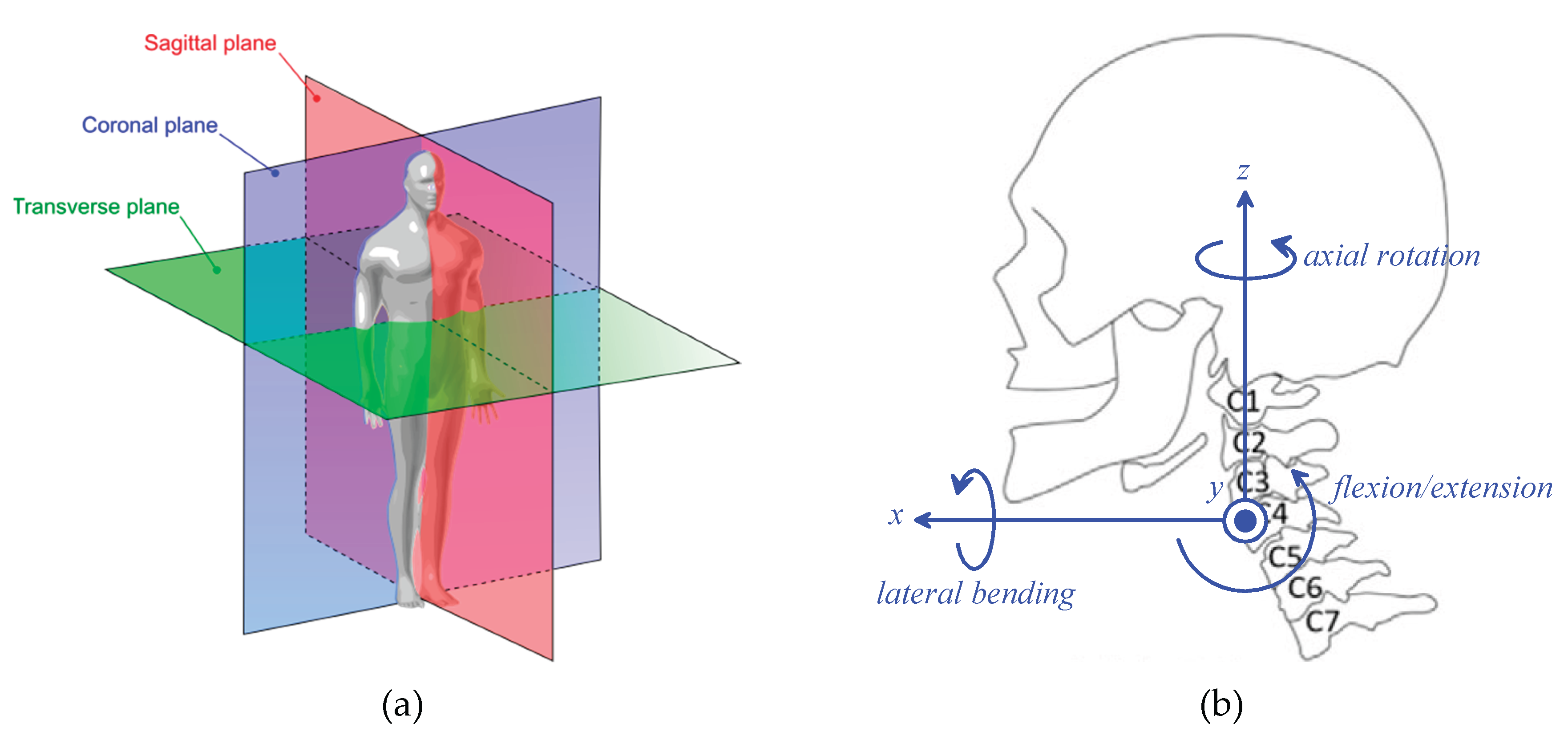
Figure 2.
Kinematic schemes of the spherical mechanisms of type RRR-RRS (a) and of type RRU-RRS (b) where point C is the SMC.
Figure 2.
Kinematic schemes of the spherical mechanisms of type RRR-RRS (a) and of type RRU-RRS (b) where point C is the SMC.
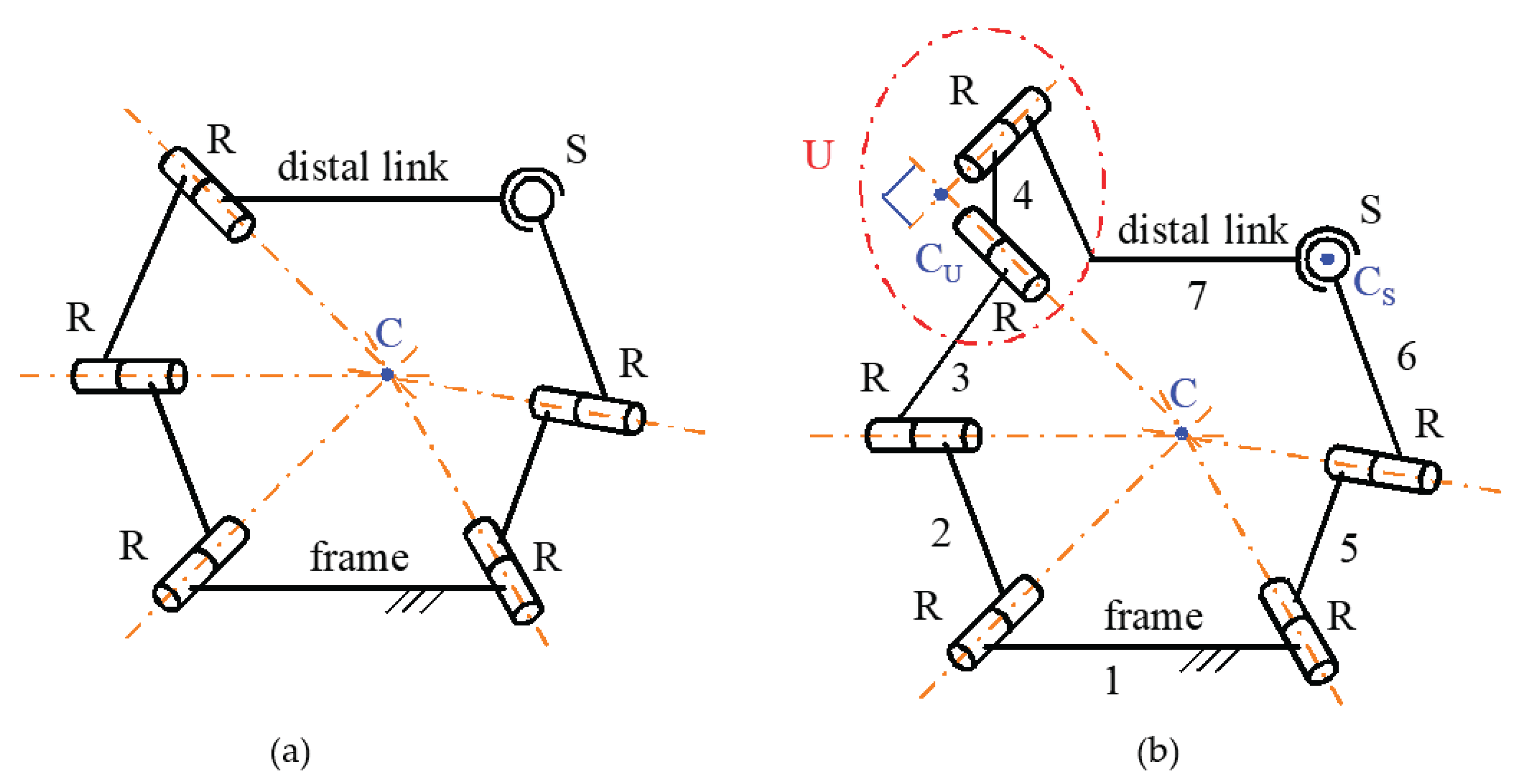
Figure 3.
Notations.
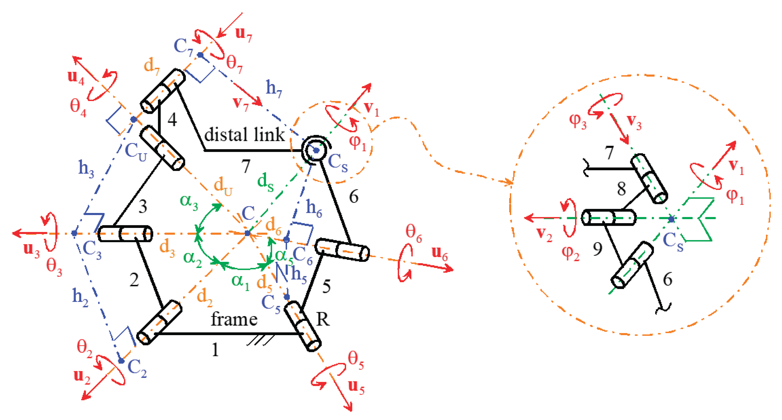
Figure 4.
Frame (link 1) and distal link (link 7) at a generic configuration together with the Cartesian reference systems Cxfyfzf, fixed to the frame, and Cxdydzd, fixed to the distal link.
Figure 4.
Frame (link 1) and distal link (link 7) at a generic configuration together with the Cartesian reference systems Cxfyfzf, fixed to the frame, and Cxdydzd, fixed to the distal link.
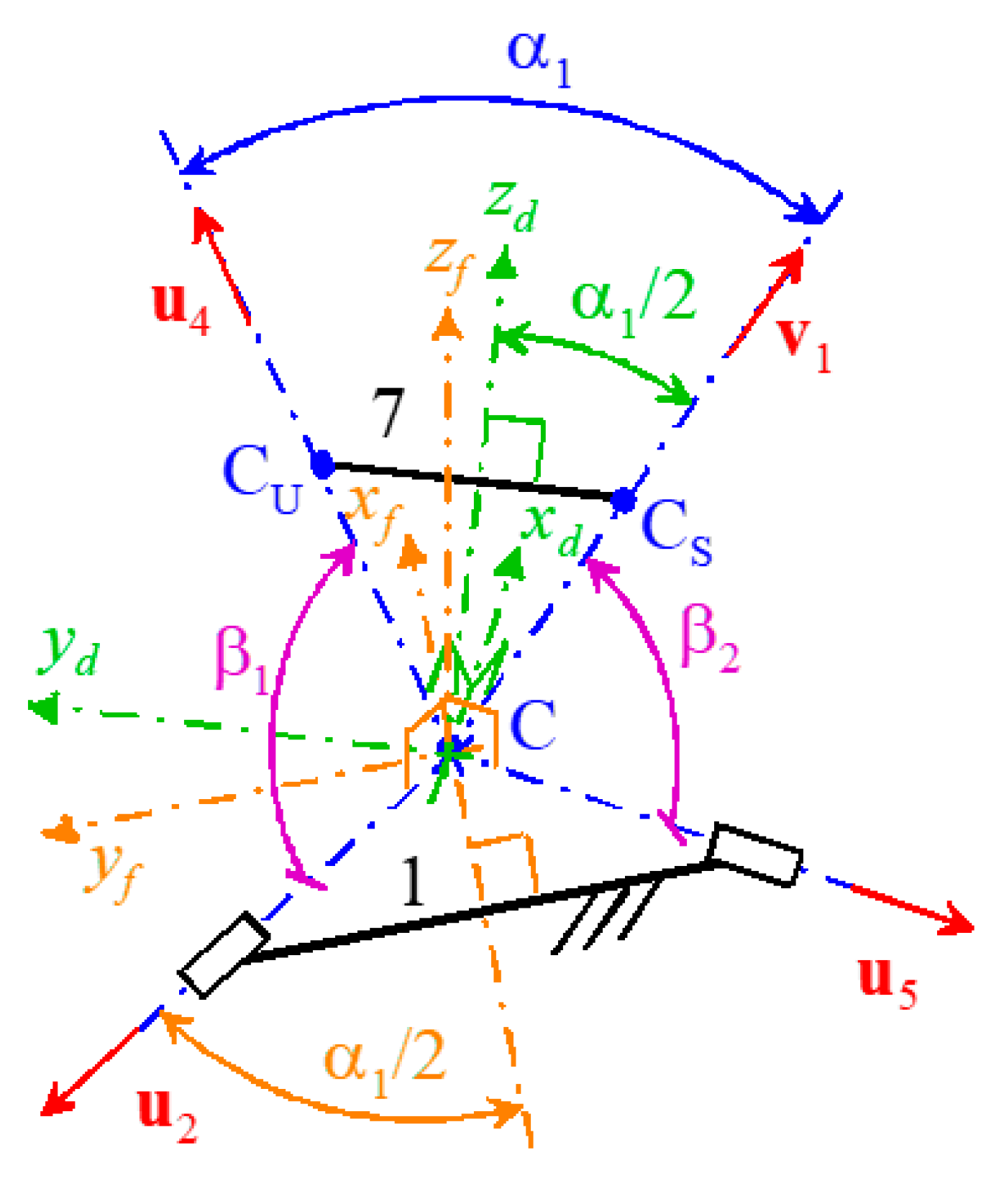
Figure 5.
3D kinematic model of the neck brace with the sizes of Table 5 and the distal link at the neutral position (the circular ring of the distal link is the harness that fixes it to the patient forehead).
Figure 5.
3D kinematic model of the neck brace with the sizes of Table 5 and the distal link at the neutral position (the circular ring of the distal link is the harness that fixes it to the patient forehead).
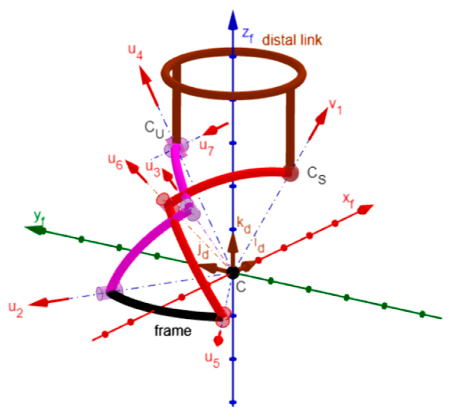
Figure 6.
3D kinematic model of the neck brace with the sizes of Table 5 and the distal link at the maximum Extension (a) and at the maximum Flexion (b).
Figure 6.
3D kinematic model of the neck brace with the sizes of Table 5 and the distal link at the maximum Extension (a) and at the maximum Flexion (b).
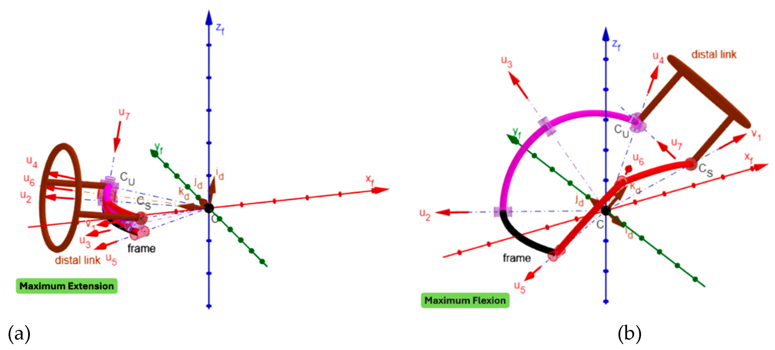
Figure 7.
3D kinematic model of the neck brace with the sizes of Table 5 and the distal link at the maximum left Lateral Bending (a) and at the maximum right Lateral Bending (b).
Figure 7.
3D kinematic model of the neck brace with the sizes of Table 5 and the distal link at the maximum left Lateral Bending (a) and at the maximum right Lateral Bending (b).
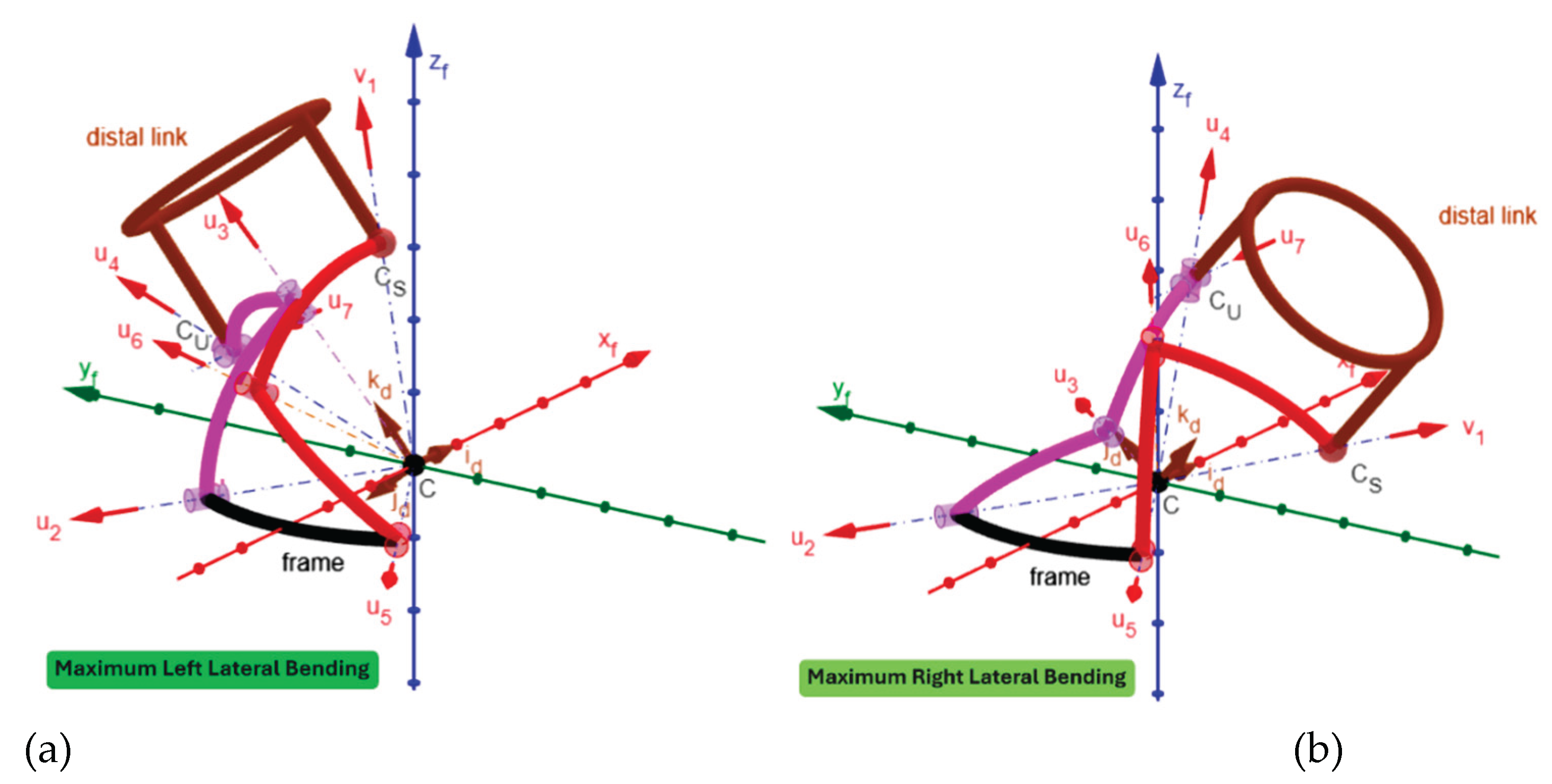
Figure 8.
3D kinematic model of the neck brace with the sizes of Table 5 and the distal link at the maximum left Axial Rotation (a) and at the maximum right Axial Rotation (b).
Figure 8.
3D kinematic model of the neck brace with the sizes of Table 5 and the distal link at the maximum left Axial Rotation (a) and at the maximum right Axial Rotation (b).
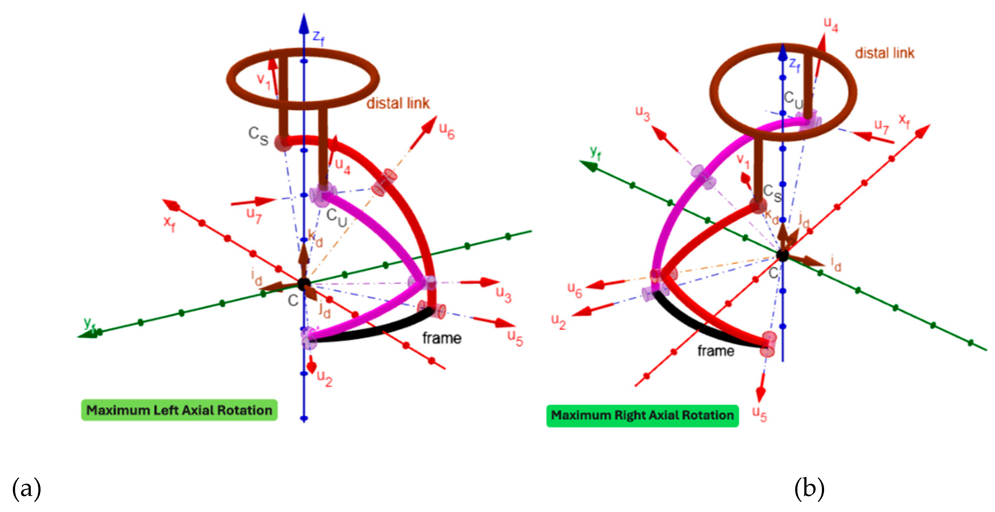
Figure 9.
Double parallelogram mechanism mounted on the frame of the neck brace: (a) projection in the sagittal plane, (b) 3D view.
Figure 9.
Double parallelogram mechanism mounted on the frame of the neck brace: (a) projection in the sagittal plane, (b) 3D view.
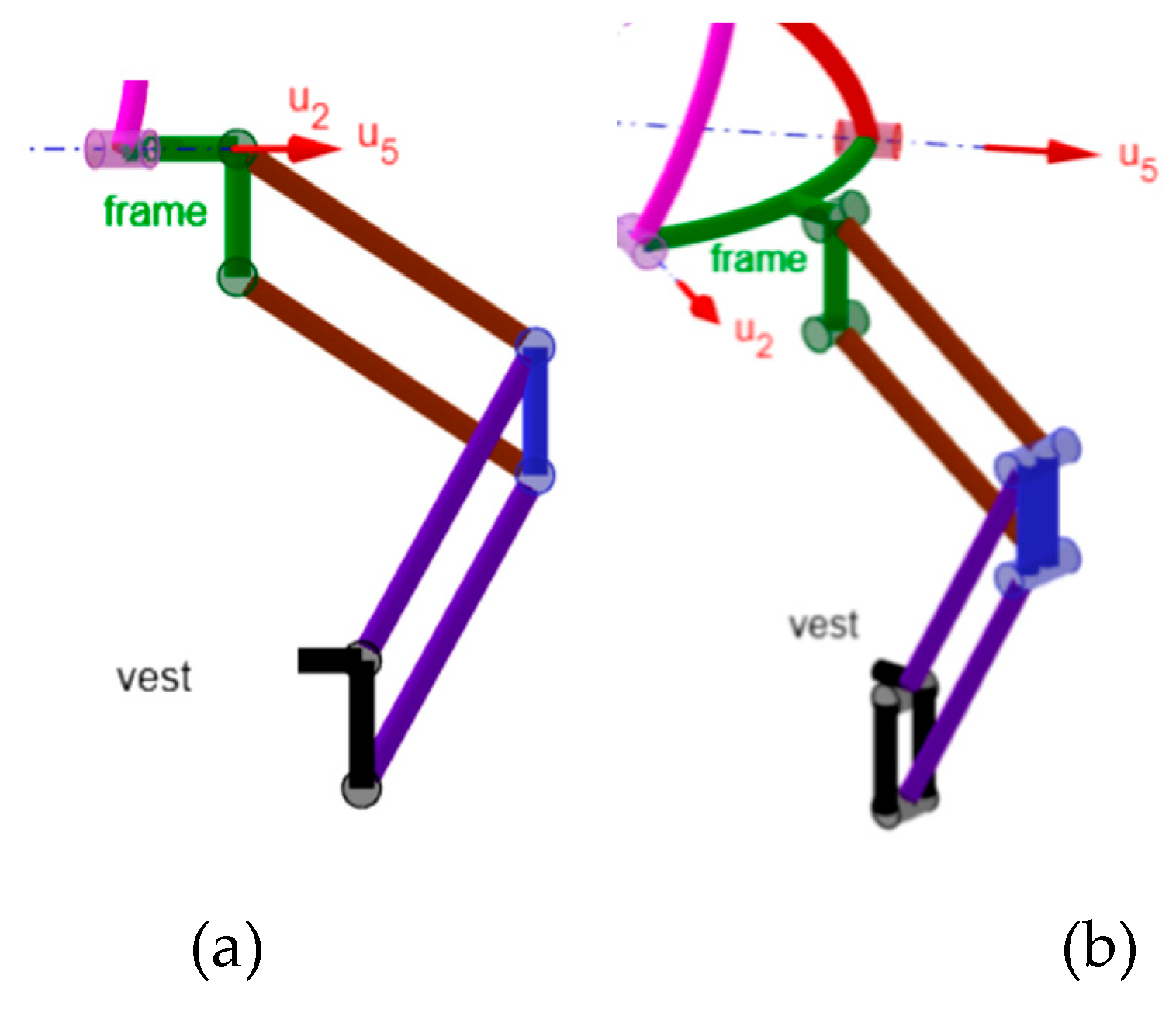
Figure 10.
RRU-RRS spherical neck brace at the neutral position combined with a double parallelogram mechanism that moves point C in the sagittal plane: (a) 3D view, and (b) projection in the sagittal plane.
Figure 10.
RRU-RRS spherical neck brace at the neutral position combined with a double parallelogram mechanism that moves point C in the sagittal plane: (a) 3D view, and (b) projection in the sagittal plane.
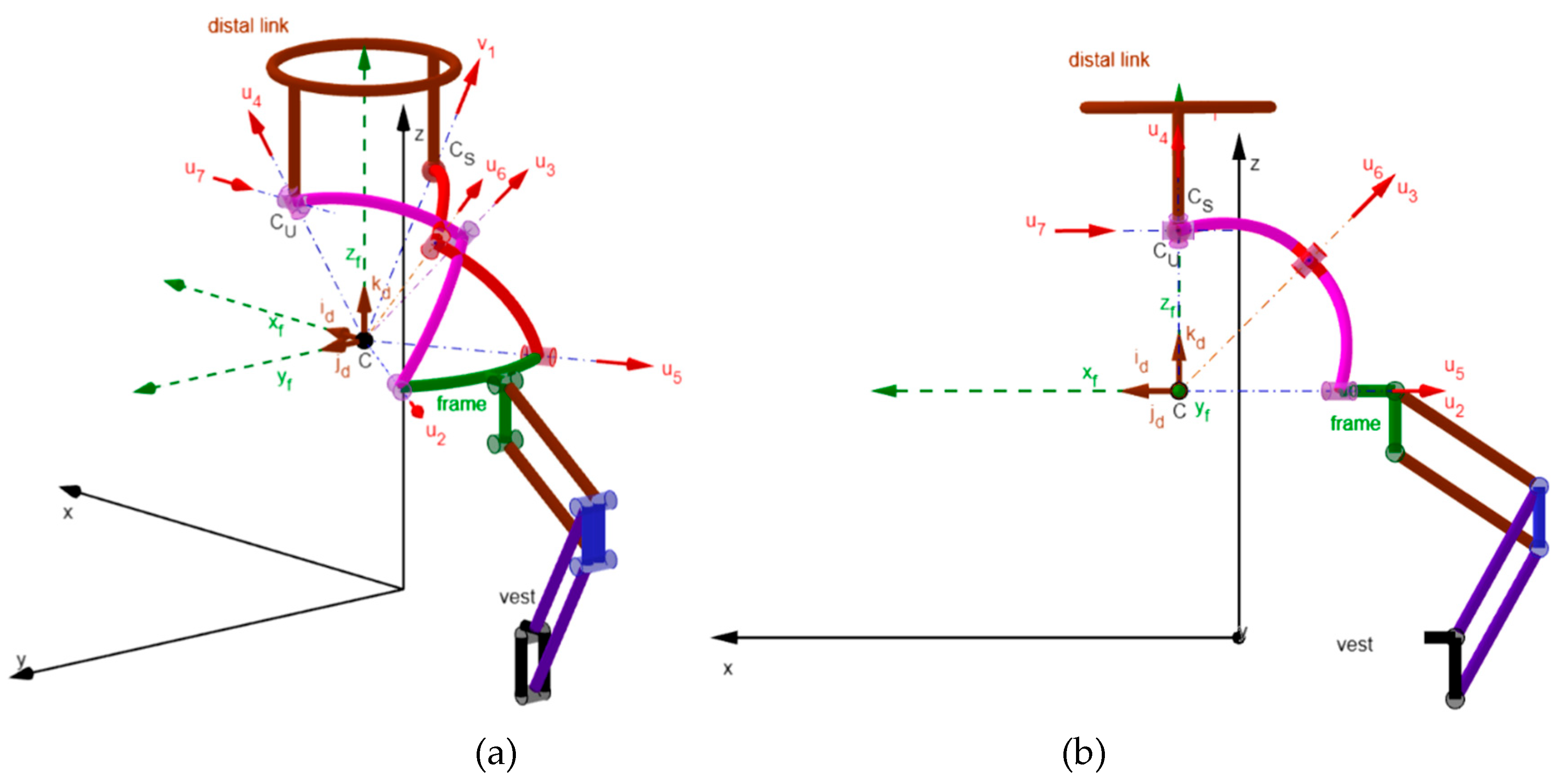

Table 1.
Approximate ROM for the Three Planes of Movement (adapted from [21]).
Table 1.
Approximate ROM for the Three Planes of Movement (adapted from [21]).
| Joint or Region | Flexion(+)/Extension(−) (Sagittal plane, (°)) |
Axial Rotation (Horizzontal plane, (°)) |
Lateral Bending (Coronal plane, (°)) |
|---|---|---|---|
| O-C1 joint | +5 / −10 | Negligible | About ±5 |
| C1-C2 joint | +5 / −10 | ± 35 ÷ 40 | Negligible |
| C2-C7 region | + 35 ÷ 40 / − 55 ÷ 60 | ± 30 ÷ 35 | ± 30 ÷ 35 |
| Total | + 45 ÷ 50 / − 75 ÷ 80 | ± 65 ÷ 75 | ± 35 ÷ 40 |
Table 2.
Mean ROM for each intervertebral joint (adapted from [22]; the total ROMs reported in [22] have been divided by considering that axial rotation and lateral bending are symmetric with respect to the neutral position and that the flexion ROM is roughly half of the extension ROM).
| Joint | Flexion(+)/Extension(−) (Sagittal plane, (°)) |
Axial Rotation (Horizzontal plane, (°)) |
Lateral Bending (Coronal plane, (°)) |
|---|---|---|---|
| O-C1 | +5 / −10 | Negligible | About ±1.5 |
| C1-C2 | +5 / −10 | ±41.5 | Negligible |
| C2-C3 | +4 / −8 | ±3 | ±7 |
| C3-C4 | +6 / −11 | ±6.5 | ±7 |
| C4-C5 | +7 / −12 | ±6.5 | ±7 |
| C5-C6 | +7 / −14 | ±6.5 | ±7 |
| C6-C7 | +8 / −15 | ±7 | ±7 |
| Total | + 42 / − 80 | ±71 | ±36.5 |
Table 3.
Design requirements for the ROM of a dynamic neck brace.
| Flexion(+)/Extension(−) (Sagittal plane, (°)) |
Axial Rotation (Horizzontal plane, (°)) |
Lateral Bending (Coronal plane, (°)) |
|
|---|---|---|---|
| ROM | + 50 / − 80 | ± 75 | ± 40 |
Table 4.
Maximum values of β1 and β2, computed through Eqs. (35a) and (35b), which correspond to the extreme values of the ROMs reported in Table 3 (the computed values of β1 and β2 have been rounded up to degrees).
Table 4.
Maximum values of β1 and β2, computed through Eqs. (35a) and (35b), which correspond to the extreme values of the ROMs reported in Table 3 (the computed values of β1 and β2 have been rounded up to degrees).
| Rotation | (ψ1, ψ2, ψ3) (°) |
β1 * (°) |
β2 * (°) |
|---|---|---|---|
| Flexion | (0, 50, 0) | 109 | 109 |
| Extension | (0,−80, 0) | 9 | 9 |
| Left Axial Rotation | (75, 0, 0) | 62 | 111 |
| Right Axial Rotation | (−75, 0, 0) | 111 | 62 |
| Right Lateral Bending | (0, 0, 40) | 95 | 62 |
| Left Lateral Bending | (0, 0, −40) | 62 | 95 |
* The values of β1 and β2 have been rounded up to degrees
Table 5.
Values of the geometric constants of the RRU-RRS neck brace that make it satisfy all the design requirements of Table 3.
Table 5.
Values of the geometric constants of the RRU-RRS neck brace that make it satisfy all the design requirements of Table 3.
| α1 (°) |
α2 (°) |
α3 (°) |
α5 (°) |
h6/dS | h7/dS | d7/dS | dU/dS |
|---|---|---|---|---|---|---|---|
| 60 | 56 | 56 | 56 | 0.829 | 1 | 0 | 1 |
Disclaimer/Publisher’s Note: The statements, opinions and data contained in all publications are solely those of the individual author(s) and contributor(s) and not of MDPI and/or the editor(s). MDPI and/or the editor(s) disclaim responsibility for any injury to people or property resulting from any ideas, methods, instructions or products referred to in the content. |
© 2025 by the authors. Licensee MDPI, Basel, Switzerland. This article is an open access article distributed under the terms and conditions of the Creative Commons Attribution (CC BY) license (http://creativecommons.org/licenses/by/4.0/).
Copyright: This open access article is published under a Creative Commons CC BY 4.0 license, which permit the free download, distribution, and reuse, provided that the author and preprint are cited in any reuse.


