1. Introduction
People with lower limb physical impairments, where the upper limbs are the sole means of mobility, have historically relied on Handbikes. These devices are user-friendly, suitable for various users, flexible, and adaptable. They are simple, intuitive, require minimal physical effort, and have dimensions suitable for user reach, manipulation, and operation [
1]. Approximately 73 million people with disabilities require the use of a wheelchair. Unfortunately, 80% of them live in low-resource countries, which makes it difficult for them to access electric wheelchairs. These wheelchairs typically have a market price of at least
$1000, approximately 12 times more expensive than conventional wheelchairs. Although manual wheelchairs are more affordable, they present challenges in terms of movement efficiency and can cause fatigue and injuries to the chest and shoulder muscles due to the effort required to move them. Handbikes are utilized to enhance the mobility of individuals with disabilities through electric, manual, or hybrid traction [
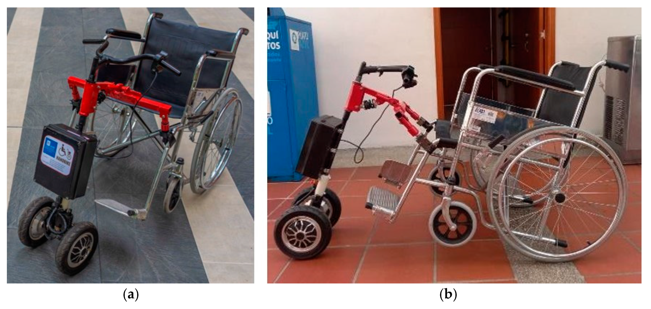
1] as seen in
Figure 1.
Currently, handbikes have become a significant mobility aid in sports, recreation, and outdoor mobility for individuals with lower limb impairments [
2]. Handbiking primarily improves fitness and enables individuals to achieve independence in outdoor mobility [
3]. Handbikes are known to be energetically less demanding compared to hand rim wheelchair propulsion, and due to favorable mechanics, they are assumed to impose lower mechanical strain [
4].
The World Health Organization has estimated that 1.3 billion people worldwide live with a disability, with at least 80 million people requiring the use of a wheelchair for mobility [
5,
6]. Wheelchair users are more likely to experience shoulder pain due to daily activities such as transferring and weight relief tasks [
7,
8]. Other physical challenges, such as impaired balance, strength limitations, and mobility disabilities, are more prevalent among wheelchair users [
9] and are the most common risk factors for falls, which can lead to severe consequences.
A statistical study on the growth of wheelchair users shows a significant increase in the prevalence of wheelchair use since 2015 compared to the years 2011 and 2013. Additionally, the rate of pain among older wheelchair users ranged from 68.2% people in 2019 to 76.3% in 2015 [
9]. Addressing physical problems is crucial for improving health and well-being. Compared to non-wheelchair users, older adults who use wheelchairs are more likely to experience physical and health problems and are less likely to go outside [
10]. This area of research would benefit from a more comprehensive examination, including extra-individual factors, such as the physical and socio-cultural environment that may influence wheelchair mobility [
9,
10].
There is a growing trend in studying the biomechanics of wheelchair use to better understand the forces and torques involved in daily activities. Clinical guidelines and findings from individuals with paraplegia indicate that those experiencing higher levels of shoulder pain tend to apply higher maximal total force to the pushrim [
11]. Additionally, the propulsion force is applied less smoothly, often resulting in a higher push frequency [
12].
Regarding handbikes, Baronio Gabriele et al. conducted a project focused on prototyping, testing, and redesigning a three-wheel trekking wheelchair for accessible tourism applications. The goal was to enable accessible tourism for everyone. Their study included analyzing the physical efforts required by the users. Testing was conducted using both quantitative and qualitative methods. [
13].
Guerra S. conducted a study on various transmission mechanisms and steering systems for the Handbike. An important aspect of the study involved a braking simulation, which concluded that the selected materials would provide a safety factor of 2.3, withstanding a reaction force of 300N. [
14]
On the other hand, Quezada proposes the design of a prototype Handbike with electric assistance, intended for attachment to a wheelchair. Their approach begins with an in-depth study focusing on the ergonomics of the system, emphasizing its critical role in achieving a well-designed handbike. Additionally, Quezada outlines an effective procedure for the ideal manufacturing process of the handbike. [
15]
Camacho presents a comprehensive approach to the design and manufacturing of a hybrid Handbike, starting from its conceptualization. In his design, Camacho emphasizes the importance of raising the wheelchair at least 8° from the ground. This elevation ensures that the front wheels maintain continuous contact with the ground, while allowing the user to maintain a comfortable posture, promoting proper neck and back alignment for enhanced visibility and propulsion. [
16]
This paper presents the development of a prototype electromechanical Handbike designed to attach to conventional wheelchairs. The primary objectives include meeting the ergonomic requirements of the user, enhancing energetic efficiency, ensuring ease of use, and adapting to the terrain conditions in Bucaramanga—Colombia, the city where this research was conducted.
2. Materials and Methods
2.1. Methodology
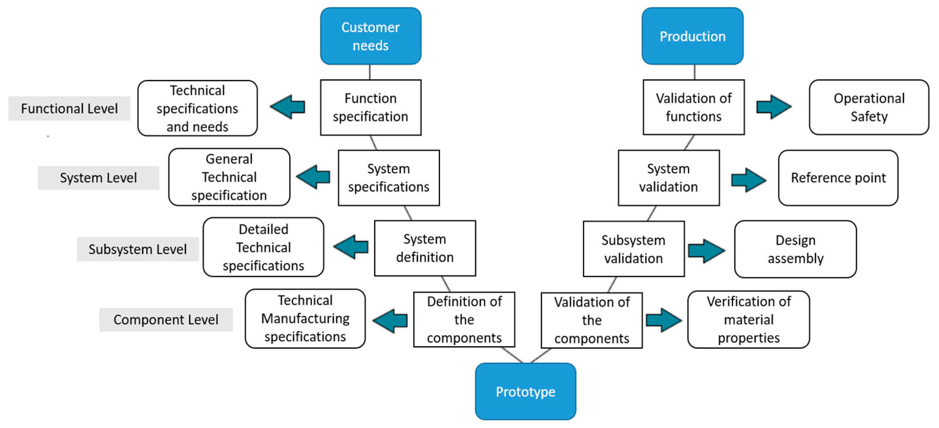
The development of the electromechanical Handbike was based on the V-model methodology [
17], which is specifically adapted for the design of mechatronic systems. This methodology provides a graphical representation of the system development life cycle, structuring the project into different levels: functional, system, subsystem, and components. Each stage ensures that appropriate validation is carried out, allowing for rigorous design and construction while ensuring that each component works correctly before being integrated into the final system, see
Figure 2.
At the functional level, a set of technical specifications was defined based on user needs, using a standard wheelchair model to facilitate the preliminary sizing of the device. Subsequently, at the system level, the general technical specifications of the Handbike were outlined, including the mechanical, electrical, and control design. This systematic approach continues with the identification and design of subsystems, where detailed technical specifications are provided for the Handbike’s coupling mechanism, ergonomics, and speed control. Finally, at the component level, each element of the device is defined and validated prior to full integration, ensuring that each subsystem operates independently and correctly before moving on to the complete validation of the prototype.
2.5. Mechanical Design
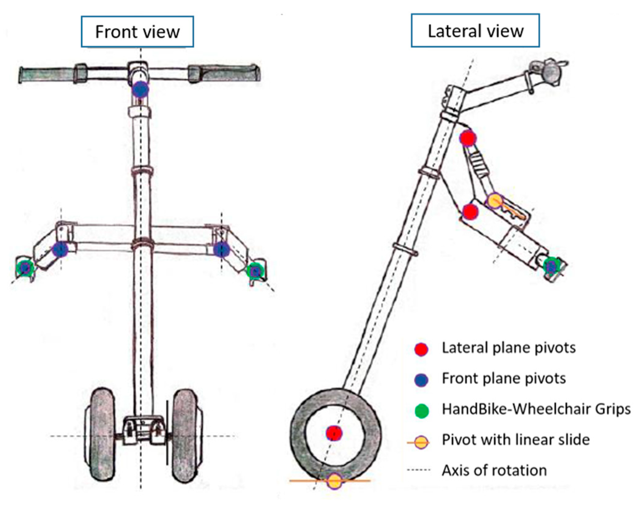
The design of the Handbike is made from a freehand model, see
Figure 3, which shows each of the views of the Handbike and the different joints with the respective pivots.
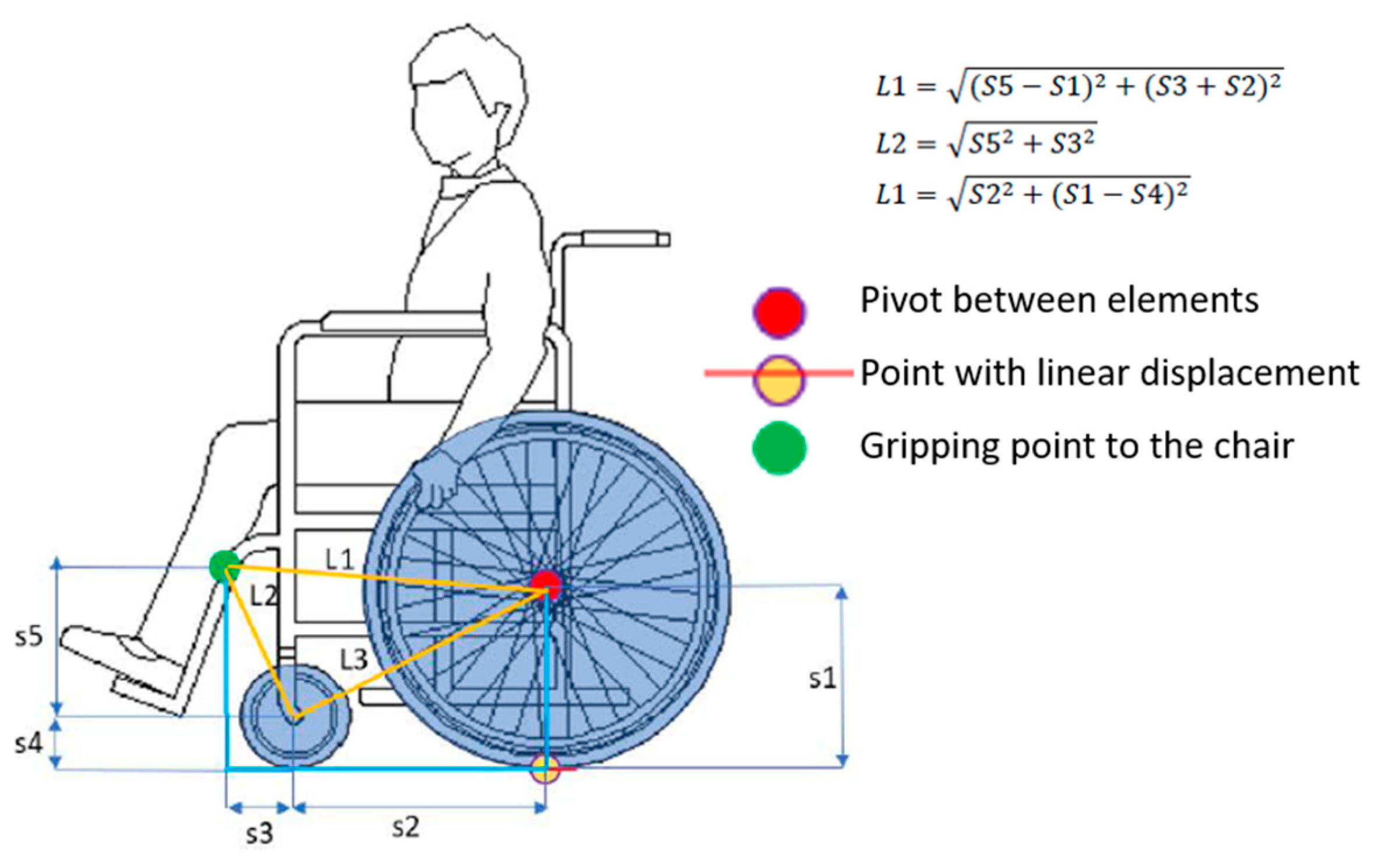
Once the conceptual design was done, the dimensioning of the wheelchair and also of the test person or Dummy was performed.
Figure 4 shows the sizing of the wheelchair, where the necessary measurements for the design of the parameterized handbike are shown, and
Table 1 defines the numerical values of these measurements. This, in order to achieve the most universal coupling to any conventional wheelchair.
Next, the characterization of the Dummy is done. This given that a person is directly related to the operation of the Handbike, thus affecting the structural design, the statics/dynamics of the system and also the different components to be acquired for the device. The Dummy was selected taking into account the average dimensions of an adult male, obtaining the data shown below: Height: 175 cm, Age: 30-50 years and Weight: 75 kg.
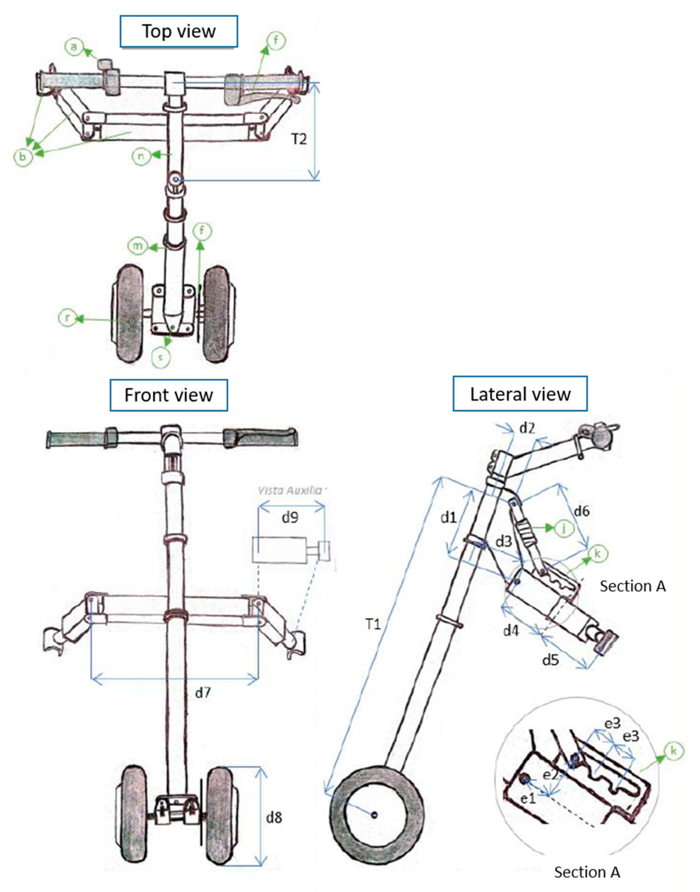
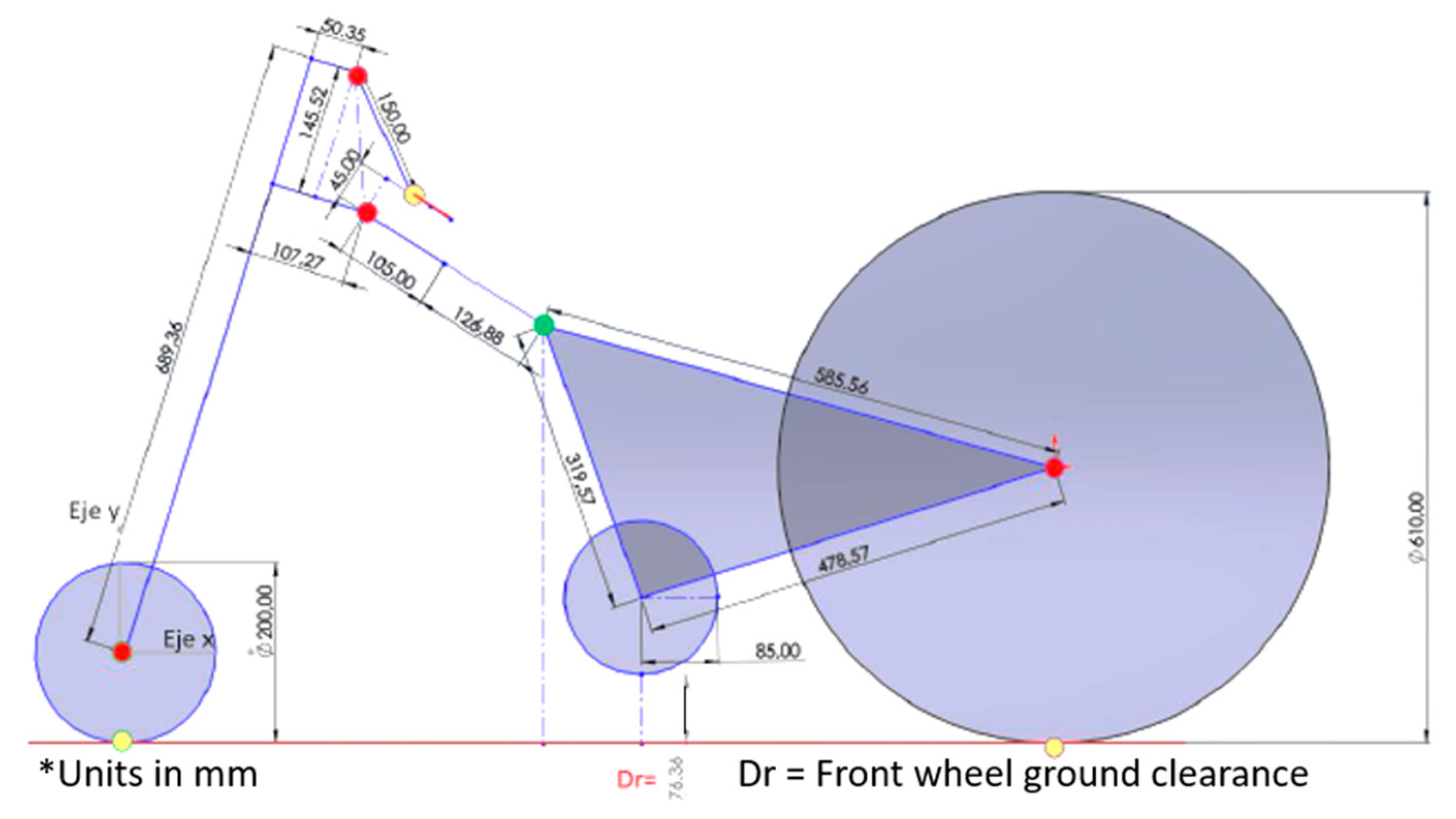
Once all the parameterization and identification of the variables to be considered for the design of the Handbike was done, freehand sketches of the device were made with their respective dimensions, see
Figure 5 and
Table 2 and
Table 3.
In addition, the sketch of the coupling mechanism between the Handbike and the wheelchair was made in the CAD software (
Figure 6). Note that the front wheel of the wheelchair is 7.63 cm above ground level to present an ergonomic design for the user.
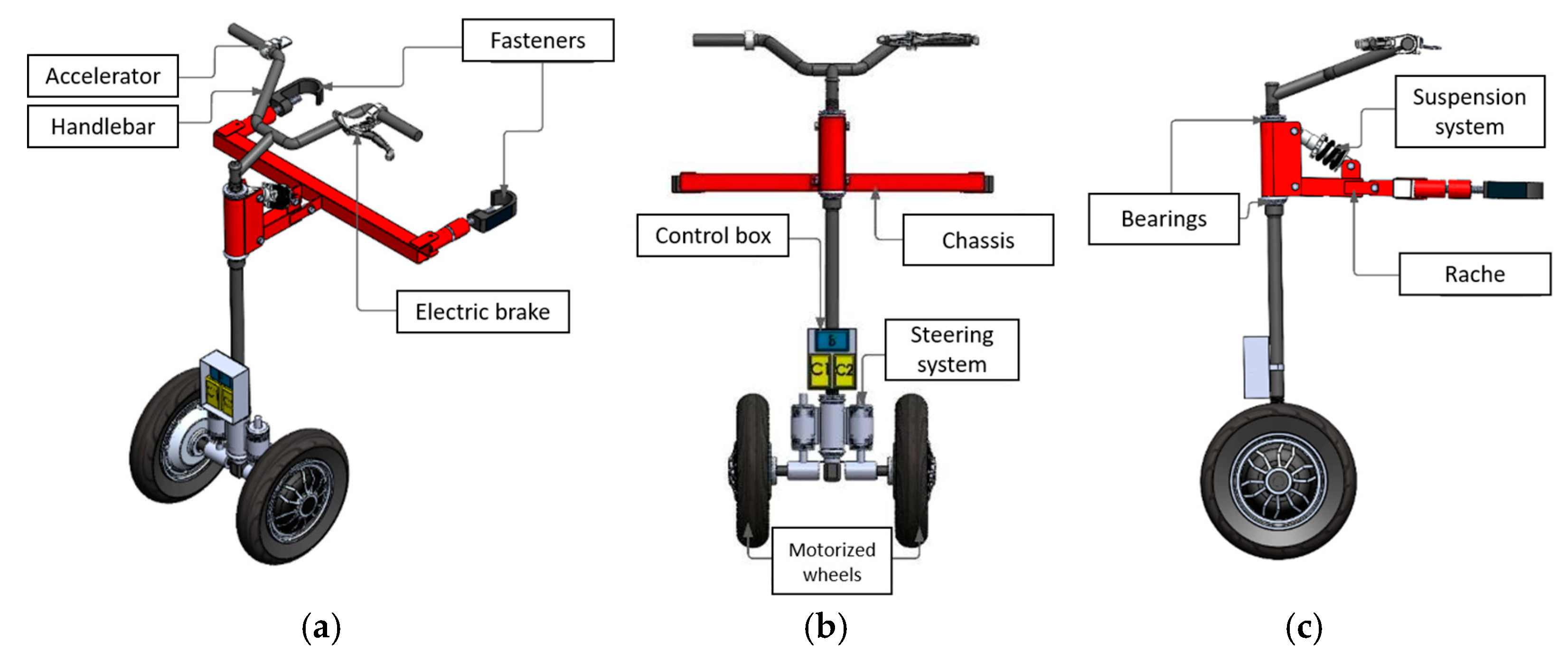
2.6. CAD Model of the HandBike
The CAD model of the device is made. The
Figure 7 shown details the different views of the device.
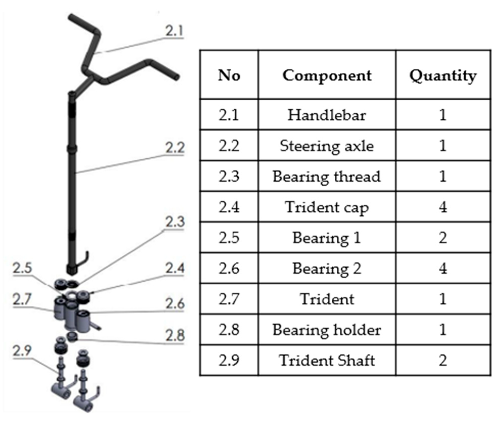
The steering system consists of several standardized bicycle components that did not require construction from scratch.
Figure 8 below shows in detail the designed model along with a listing of the components and quantities required.
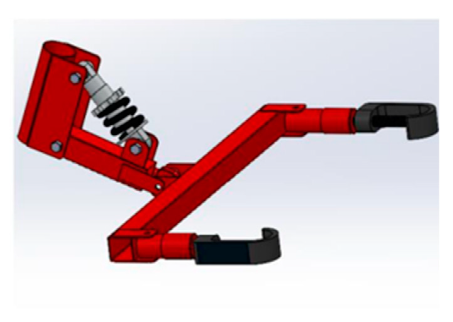
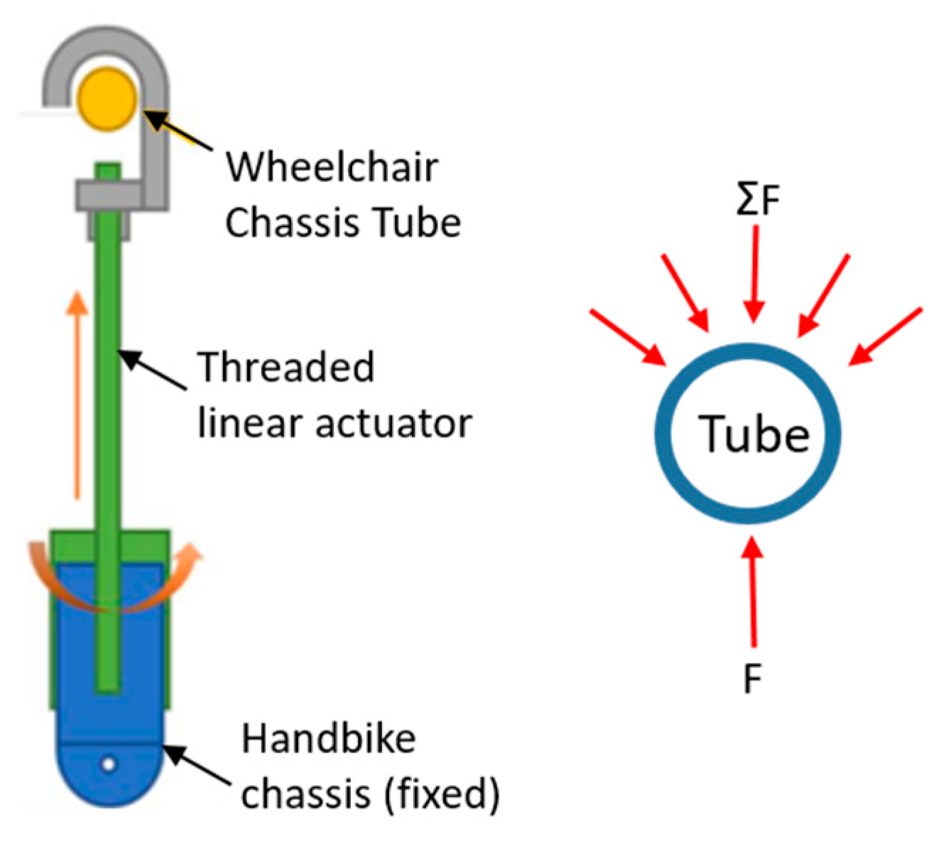
The chassis of the HanBike consists of a system of rache and shock absorber, likewise in this component are assembled the fasteners that allow the coupling to the wheelchair, as shown in
Figure 9.
The fasteners consist of a steel sheet bent to the tubular profile of the wheelchair frame and a screw mechanism (linear actuator), which is adjusted until the wheelchair and the handbike are coupled.
Figure 10 below shows a picture of how the mechanism works.
2.7. FEM Simulation
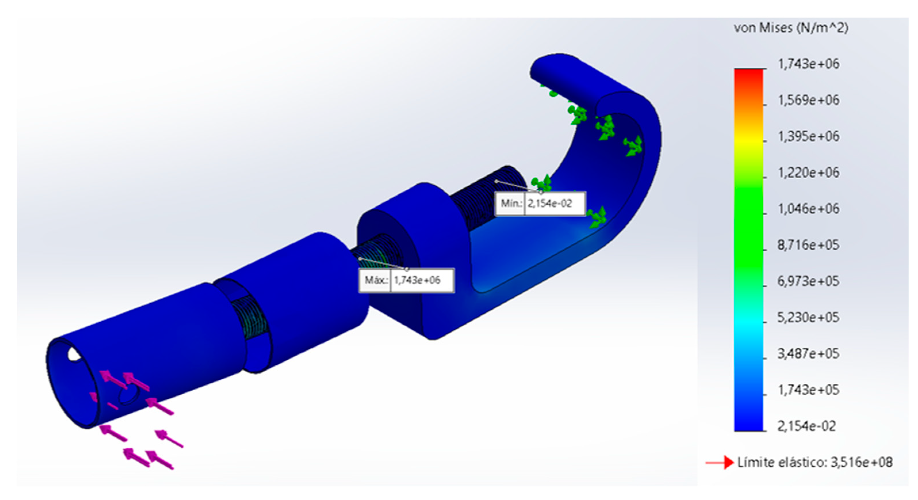
A finite element simulation is developed in CAD/CAE software, to analyze the resistance of each of the components of the device, configuring the materials with which the handbike will be built and determine whether the selected material and the designed geometry supports the loads to which it will be subjected in a real environment. For this purpose, the most critical components of the assembly are selected, and the results for each component are shown below. The loads to which each component is subjected is 10 [N].
Figure 11 shows the behavior of the component subjected to loads, this element presents a maximum von Misses stress of 1.743 MPa, which is generated on the bolt that joins the component parts.
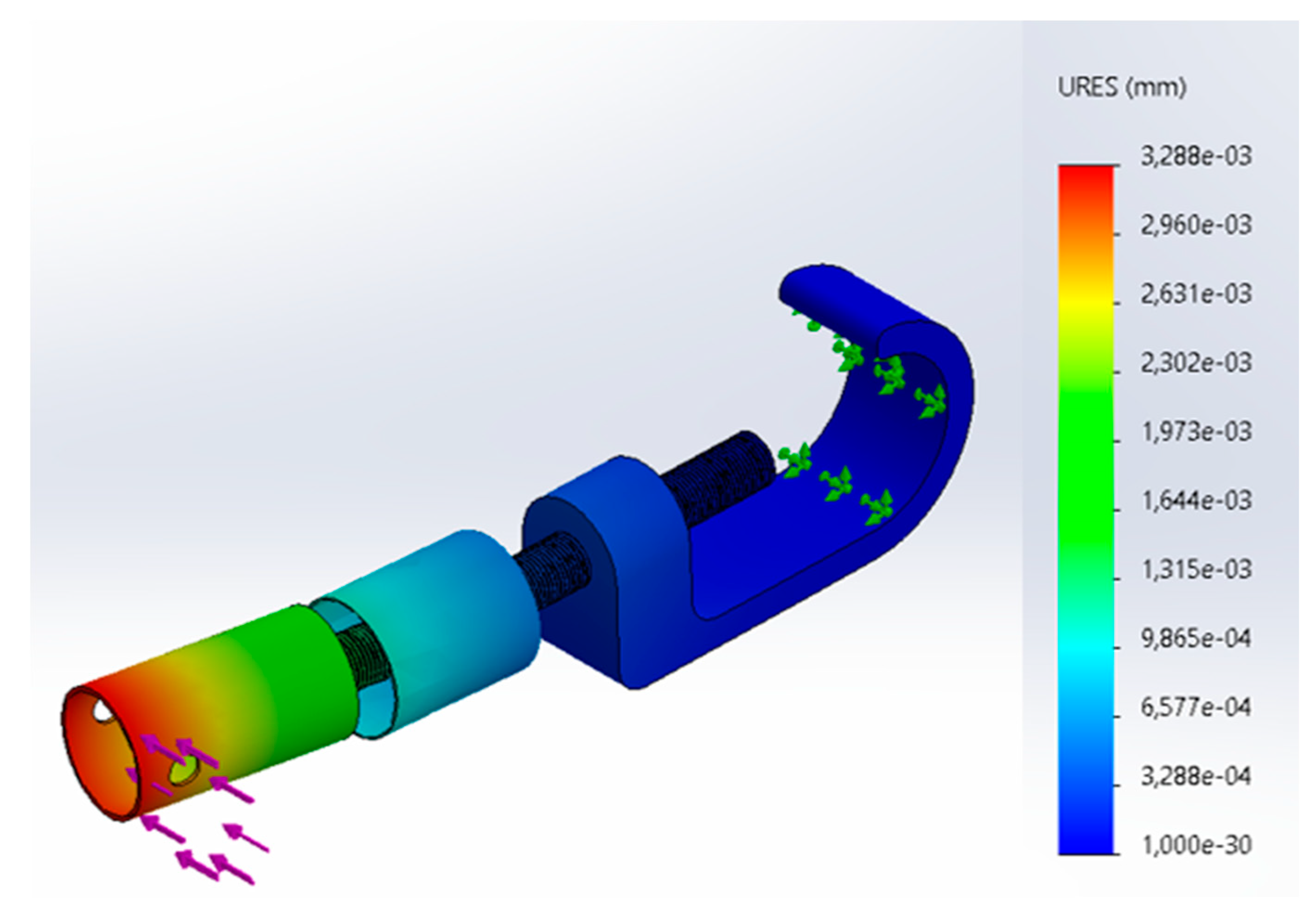
Figure 12 shows the deformation suffered by the part due to the applied loads, such deformation reaches a maximum value of 0.003288 [mm] in the part where the handbike and the fastener are connected. Regarding the safety factor, it can work under the simulated conditions since the minimum value is 200, this indicates that this component could be simplified or the design could be optimized or a less ductile material could be selected, and with this also reduce the weight of the handbike device.
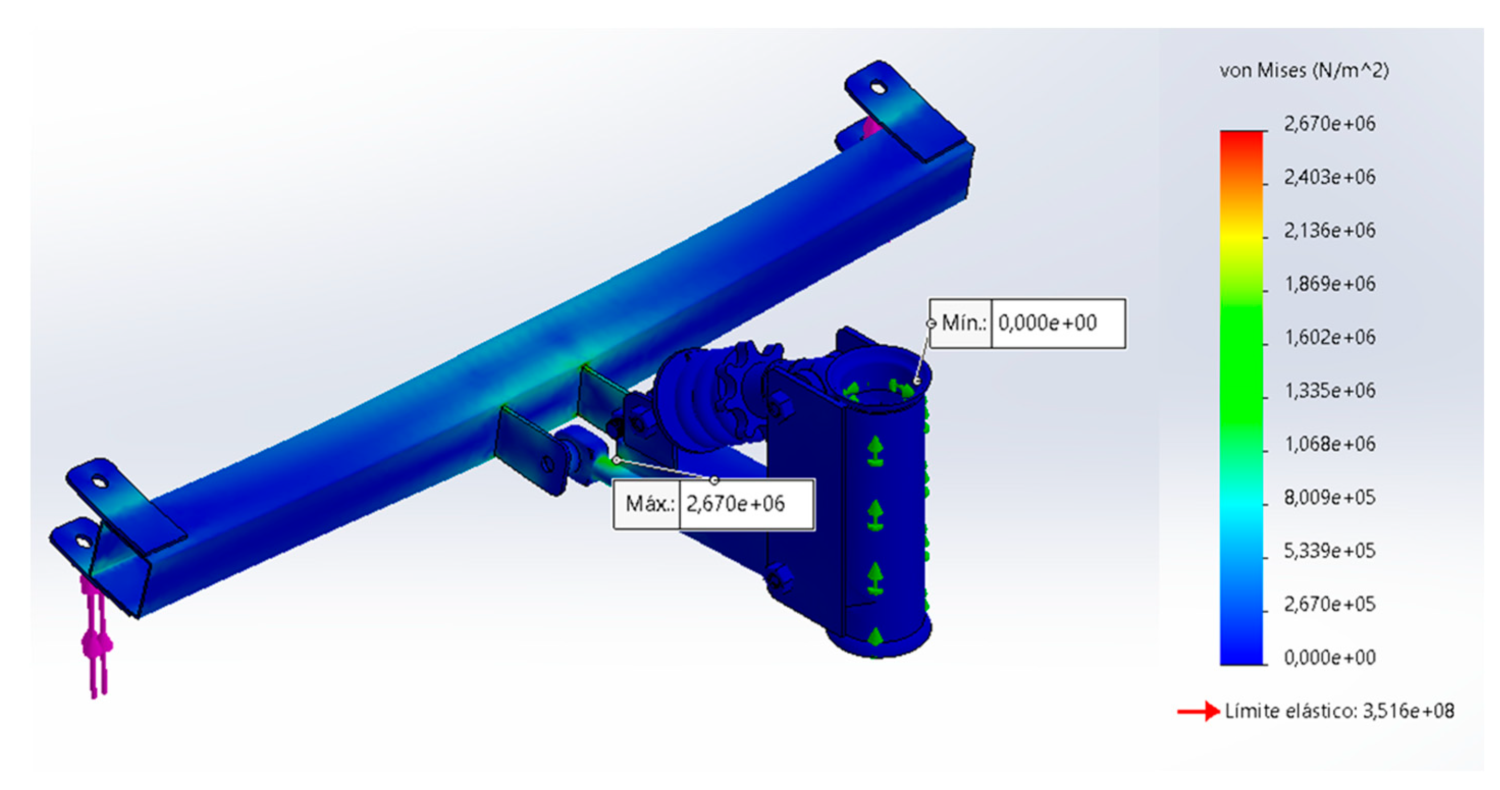
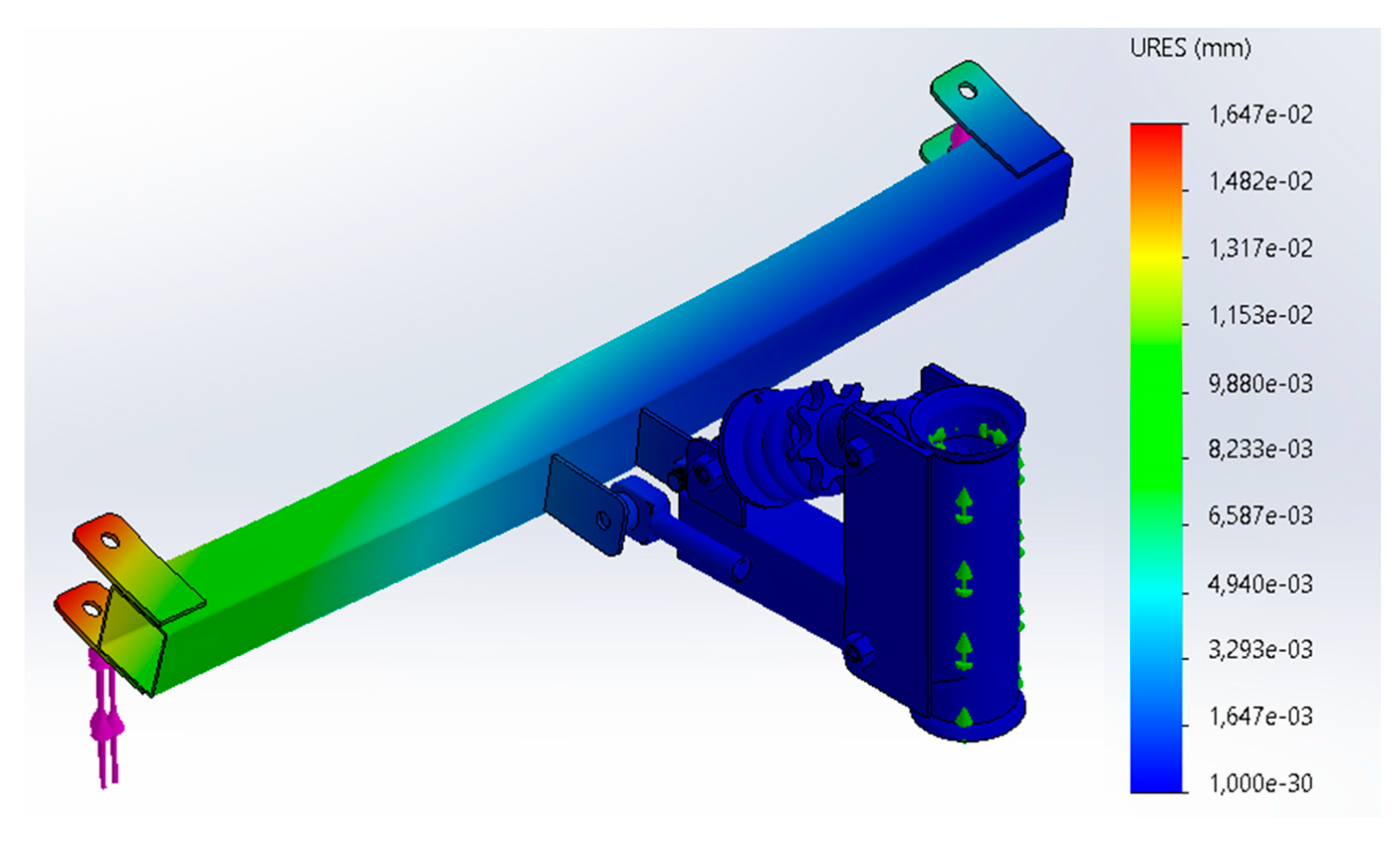
A structural simulation was also performed to verify the strength of the chassis under the previously defined loads.
Figure 13 shows the stresses and Von Mises stress results for the chassis. The maximum stress on the chassis is located over the ratchet area, with a maximum von Misses value of 2,670 MPa.
The maximum deformations that occur on the chassis are located on the ends where the fasteners are coupled, such deformation reaches a maximum value of 0.01647 [mm]. The safety factor of this element takes minimum values of 131, which indicates that the component can withstand the operating conditions.
2.8. Physical Model
Initially, the free body diagram corresponding to the forces acting on the handbike in an inertial way, i.e., statically, is made. This is necessary to perform the power and torque calculation required for the selection of the electric motors. Where is the reaction force plus the weight of the wheel, is the critical force of the motor, is the normal force of the handbike wheel, is the normal force of the wheelchair wheel, are the friction forces of handbike wheel and wheelchair wheel respectively and is the reaction force of the wheelchair wheel plus its own weight.
Figure 15.
Free body diagram (FBD) of the system.
Figure 15.
Free body diagram (FBD) of the system.
From the FBD, Newton’s third law is applied as shown below:
For the system to start moving, the force must be slightly greater than the sum of the opposing forces . From the above, it is obtained that the tensile force that the motors must apply to break the inertia on a horizontal plane is :
The same steps shown above were also applied to break the inertia of the system on a 12° slope, resulting in a force of 57.76 [N]. To calculate the power of the electric motors, the work and energy equations are applied to determine the torque that each motor must exert to move the handbike from inertia to a final speed of 15 [km/h] over 20 meters, shown below:
Considering that the work done by the motors corresponds to the following equation:
Equation 8 is replaced in equation 6, and the force to be exerted by the motors to meet the conditions set at the design stage is obtained:
1) For the case of a horizontal plane:
2) For the case of an inclined plane 12°:
Finally, the torque required by the motors to meet the above conditions is determined:
With the above and considering that the power is required, the torque equation of a motor is applied, and the power is cleared as shown below:
The torque required to overcome a 12° slope is used, since this would meet both conditions and would result in a power of approximately A motor of approximately half horsepower is required, however, for this research a set of two motors of 0.5 hp each will be used, thus meeting the required power levels and maintaining a good power safety factor to avoid overheating of the electronics.
2.9. Electrical Design
The electromechanical system consists of several elements, such as motors, controllers and throttle. The selected motors are brushless, and have a supply voltage of 36 V, a nominal speed of 800 RPM, a power of 350 W and a current consumption of 1–8 Ampere-hours. Once the motors have been selected, a battery is proposed as the power supply. This battery has a maximum voltage of 40 V, a capacity of 4.4 Ampere-hours and an energy of 158.4 Watt-hours. Once all components have been selected, a wiring diagram is constructed as follows:
Figure 16.
Schematic diagram of motor drives.
Figure 16.
Schematic diagram of motor drives.
2.10. Construction and Assembly of the HandBike
For the construction of the Handbike, the design was divided into three main subsystems: the steering system, the chassis system, and the electromechanical system. The electromechanical system is composed of several key components, including motors, controllers, and the accelerator. The controller cards, responsible for speed and load regulation, are housed within a sealed enclosure positioned along the main axis of the steering system to ensure protection and durability.
The chassis and steering system of the Handbike were constructed using chromoly steel, known for its strength and durability. The manufacturing process involved cold bending of the tubing, ensuring precise angles and shapes critical to the design. The components were then joined using Shielded Metal Arc Welding (SMAW), with E6013 coated electrodes applied to create robust weld seams. During assembly, interference fits were achieved using a 10-ton manual press, ensuring a secure and precise connection of the various components. To enhance durability and aesthetics, the chassis was treated with an anti-corrosive coating, followed by a final red electrostatic paint finish.
Regarding the controller box, all electronic systems were securely housed within the sealed enclosure mentioned earlier. This box contains the charge controller circuit, speed and brake control circuits, and lithium-ion batteries. Externally, the box features only the system’s charging port and the device’s power switch, ensuring a clean and user-friendly design. The throttle cable, connected to the handlebar, also extends from this box. Additionally, the power and control cables for the two propulsion motors, located in the Handbike’s wheels, are routed from the controller box, providing efficient and reliable operation.
In
Figure 17, the final result of the constructed electromechanical Handbike device can be observed. Image A shows the device from an isometric view (diagonal), Image B provides a side view of the device, and Image C highlights some details of the assembled components.
3. Results
In order to validate the operation of the Handbike, tests corresponding to speed, adaptability and autonomy of the system were carried out. These tests were performed with three users of different weights and heights, in order to determine the reproducibility of the handbike built. Below is a table with the characteristics of the test subjects who used the handbike.
Table 4.
Characteristics of test subjects.
Table 4.
Characteristics of test subjects.
| Subjects |
Age |
Weight [Kg] |
Height [m] |
| Subject 1 |
22 |
79.8 |
1.81 |
| Subject 2 |
21 |
65 |
1.68 |
| Subject 3 |
22 |
92 |
1.72 |
Speed and autonomy tests were performed.
3.1. Speed Test
3.1.1. Straight terrain
The speed tests were performed on flat and straight terrain, in order to determine the speed of the handbike coupled to the wheelchair. The following results were obtained for a 5-lap test. The following table shows the results obtained in the speed test:
Table 3.
Characteristics of test subjects.
Table 3.
Characteristics of test subjects.
| Description |
Value |
| Max. Speed [km/hr] |
13 |
| Average Speed [km/hr] |
8 |
| Distance [m] |
0.43 |
| Time elapsed [hh:mm:ss] |
0:03:10 |
In this speed test, a maximum recorded speed of 13 km/h was obtained for all users who rode the handbike-wheelchair system. The speed reached is permissible taking into account the speed limit for these devices, which is 25 km/h.
3.1.2. Sloping Terrain
Tests were also carried out on inclined terrain in order to meet the expectations of overcoming slopes of up to 7°.
3.2. Autonomy Test
The autonomy test was performed on flat and straight terrain in order to determine the durability of the battery of the handbike system. A trip was made with a duration of 1 hour, 4 minutes and 55 seconds, and it was observed that at the end of this test the battery of the electromechanical handbike had a value of 37.9 Volts. If it is known that the test was started with the battery at its maximum charge (40 Volts) and the system stops working below 36 Volts; this yields a discharge percentage of 52.5% during the test and making a linear approximation for the complete discharge, would result in a total autonomy of the device of 2 hours 3 minutes and 39 seconds.
Table 5 shows the results of the aforementioned test. Note that in this test an average speed of around 10 km/h was maintained in order to keep the handbike in a constant and controlled operating condition.
4. Discussion
The results obtained from the speed and autonomy tests confirm the feasibility of the HandBike prototype attachable to conventional wheelchairs. First, the speed tests on flat terrain showed a maximum speed of 13 km/h, well within the acceptable range for mobility-assist devices, which typically have a speed limit of 25 km/h. Notably, the consistency of the speed across different users, regardless of their weight and height, suggests that the system is versatile and well-adapted to users with varying physical characteristics.
In terms of autonomy, the HandBike demonstrated a battery life of approximately two hours while maintaining an average speed of 10 km/h, making it suitable for short to medium-distance daily commutes. These findings are in line with previous studies on similar devices, such as those by Verdi (2016) and Quezada (2020), both of whom reported similar autonomy ranges. It is worth noting, however, that the battery life may vary depending on terrain conditions, driving style, and battery health, factors that could be explored in future research.
The finite element method (FEM) simulations conducted on critical components such as the chassis and coupling mechanisms confirmed the structural integrity of the HandBike. The high safety factors, often exceeding 100, indicate that the device is not only safe for normal use but can also withstand more demanding conditions, such as steeper inclines or heavier users.
One of the standout features of this HandBike is its ease of attachment to conventional wheelchairs, providing an affordable and accessible solution for people with disabilities, particularly in low-resource settings. This represents a significant improvement over other devices that require specific wheelchair modifications or are prohibitively expensive.
5. Conclusions
This study successfully developed and validated an electric HandBike prototype that can be easily attached to conventional wheelchairs. The speed and autonomy tests confirm the device’s functionality and adaptability to users with diverse physical characteristics. The structural simulations using the finite element method ensure the HandBike’s strength and safety, with high safety factors even under critical load conditions.
The proposed HandBike has the potential to significantly improve the mobility of individuals with disabilities by offering a cost-effective and accessible alternative to traditional electric wheelchairs. Its modular design and ability to attach to any conventional wheelchair make it a flexible and adaptable solution for various user needs.
Looking forward, future work could focus on enhancing the device’s battery life and evaluating its performance across different terrains. Additionally, incorporating more advanced control technologies could further improve the user experience.
Author Contributions
Conceptualization, S.A.A.G., D.Y.R.S.; methodology, D.AV.R., A.J.R.H. and C.F.P.C.; software, D.AV.R.; validation, D.AV.R., A.J.R.H. and C.F.P.C.; formal analysis, S.A.A.G., D.Y.R.S.; investigation, D.AV.R., A.J.R.H. and C.F.P.C.; resources, S.A.A.G.; data curation, S.A.A.G., and D.AV.R.; writing—original draft preparation S.A.A.G., writing—review and editing, S.A.A.G., D.Y.R.S.; visualization, S.A.A.G., D.AV.R.; supervision, S.A.A.G., project administration, S.A.A.G., funding acquisition, S.A.A.G., All authors have read and agreed to the published version of the manuscript.
Funding
This research was funded by Universidad Autónoma de Bucaramanga (UNAB), grant number 014-2022.
Data Availability Statement
The original contributions presented in the study are included in the article; further inquiries can be directed to the corresponding authors.
Conflicts of Interest
The authors declare no conflicts of interest.
References
- Verdi, K. (2016). Diseño de acople mecatronico para Handbike. Universidad Pontificia Catolica de Peru.
- Valent LJ, Dallmeijer AJ, Houdijk H, Slootman HJ, Post MW, van der Woude LH. Influence of hand cycling on physical capacity in the rehabilitation of persons with a spinal cord injury: a longitudinal cohort study. Arch Phys Med Rehabil. 2008 Jun;89(6):1016-22. [CrossRef] [PubMed]
- Stefan van Drongelen, Jos van den Berg, Ursina Arnet, DirkJan (H.E.J.) Veeger, Lucas H.V. van der Woude, Development and validity of an instrumented handbike: Initial results of propulsion kinetics, Medical Engineering & Physics, Volume 33, Issue 9, 2011, Pages 1167-1173, ISSN 1350-4533. (https://www.sciencedirect.com/science/article/pii/S1350453311001093). [CrossRef]
- Van der Woude LH, Dallmeijer AJ, Janssen TW, Veeger D. Alternative modes of manual wheelchair ambulation: an overview. Am J Phys Med Rehabil. 2001 Oct;80(10):765-77. Author 1, A.B. Title of Thesis. Level of Thesis, Degree-Granting University, Location of University, Date of Completion. [CrossRef] [PubMed]
- World Health Organization. (2022). Global report on health equity for persons with disabilities. World Health Organization.
- World Health Organization. Assistive technology‒fact sheet. 2018. Available at: www.who.int. [accessed 14.01.2024].
- Fullerton HD, Borckardt JJ, Alfano AP. Shoulder pain: a comparison of wheelchair athletes and nonathletic wheelchair users. Med Sci Sports Exerc. 2003 Dec;35(12):1958-61. [CrossRef] [PubMed]
- Zanotto T, Sosnoff JJ, Backus D, Yarnot R, Worikat NA, Abou L, Peterson EW, Rice LA. Characteristics and consequences of falls among people with multiple sclerosis who use wheelchairs or scooters: Differences between injurious and non-injurious falls. Mult Scler Relat Disord. 2023 May; 73:104631. Epub 2023 Mar 21. [CrossRef] [PubMed]
- Nie Q, Rice LA, Sosnoff JJ, Shen S, Rogers WA. Understanding Wheelchair Use in Older Adults From the National Health and Aging Trends Study. Arch Phys Med Rehabil. 2024 Mar;105(3):514-524. Epub 2023 Sep 20. [CrossRef] [PubMed]
- Namkee, G. Choi, Bryan Y. Choi & C. Nathan Marti (2023) Changes in Older Adults’ Frequency of Going Outside between 2020 and 2021: Associations with Health Status and Environmental Factors, Clinical Gerontologist, 46:5, 745-758. [CrossRef]
- Quaglia, G.; Bonisoli, E.; Cavallone, P. The Design of a New Manual Wheelchair for Sport. Machines 2019, 7, 31. [Google Scholar] [CrossRef]
- Arnet, U., Bossuyt, F., Beirens, B., & de Vries, W. (2023). Shoulder pain in persons with tetraplegia and the association with force application during manual wheelchair propulsion. Current Issues in Sport Science (CISS), 8(2), 091. [CrossRef]
- Baronio, G.; Bodini, I.; Motyl, B.; Uberti, S. Prototyping, Testing, and Redesign of a Three-Wheel Trekking Wheelchair for Accessible Tourism Applications. Appl. Sci. 2021, 11, 9641. [Google Scholar] [CrossRef]
- S. Domínguez Guerra, “Diseño y cálculo de handbike acoplable a silla de ruedas para paciente específico,” M.S. thesis, Universidad politécnica de Madrid, España, septiembre de 2019.
- J. Quezada y I. Quezada, “Diseño de un prototipo de Handbike con asistencia eléctrica acoplable a una silla de ruedas,” Universidad politécnica salesiana sede Cuenca, Cuenca, Ecuador, 2020.
- D. Camacho Suárez, “Diseño y manufactura de un handbike híbrido,” Universidad de los Andes, Bogotá, Colombia, diciembre de 2020.
- Titze, H.; Jäger, B.; Wenzel, C. Design Methodology in Mechatronics. In Springer Series in Advanced Manufacturing; Springer: Berlin/Heidelberg, Germany, 2012. [Google Scholar]
Figure 1.
Commercial handbike attached to a wheelchair: a) Manual, b) electric. Adapted from aktiva-mx.com.
Figure 1.
Commercial handbike attached to a wheelchair: a) Manual, b) electric. Adapted from aktiva-mx.com.
Figure 2.
Diagram of the v-methodology used.
Figure 2.
Diagram of the v-methodology used.
Figure 3.
HandBike drawing draft.
Figure 3.
HandBike drawing draft.
Figure 4.
Wheelchair sizing.
Figure 4.
Wheelchair sizing.
Figure 5.
Freehand sketches of the handbike with dimensions.
Figure 5.
Freehand sketches of the handbike with dimensions.
Figure 6.
Handbike with wheelchair scheme diagram.
Figure 6.
Handbike with wheelchair scheme diagram.
Figure 7.
CAD model of the HandBike: (a) Isometric view; (b) Front view; (c) Side view.
Figure 7.
CAD model of the HandBike: (a) Isometric view; (b) Front view; (c) Side view.
Figure 8.
Detailed CAD model of the steering system.
Figure 8.
Detailed CAD model of the steering system.
Figure 9.
CAD model of the HandBike chassis.
Figure 9.
CAD model of the HandBike chassis.
Figure 10.
Wheelchair-HandBike coupling mechanism and force distribution diagram on the chassis tube.
Figure 10.
Wheelchair-HandBike coupling mechanism and force distribution diagram on the chassis tube.
Figure 11.
Tension loads on fasteners.
Figure 11.
Tension loads on fasteners.
Figure 12.
Deformations on fasteners.
Figure 12.
Deformations on fasteners.
Figure 13.
Tension loads over the chassis.
Figure 13.
Tension loads over the chassis.
Figure 14.
Deformations over the chassis.
Figure 14.
Deformations over the chassis.
Figure 17.
Constructed Handbike coupled to a commercial wheelchair. (a) Isometric view, (b) Side view.
Figure 17.
Constructed Handbike coupled to a commercial wheelchair. (a) Isometric view, (b) Side view.
Table 1.
Typical distances of wheelchair.
Table 1.
Typical distances of wheelchair.
| Symbol |
Value [mm] |
| s1 |
305 |
s2
s3
s4
s5 |
425
157.68
85
277.96 |
Table 2.
Dimensions of Handbike.
Table 2.
Dimensions of Handbike.
| Symbol |
Dimension [mm] |
| T1 |
535–800 |
| T2 |
200–350 |
| d1 |
145,52 |
| d2 |
50,35 |
| d2 |
50,35 |
| d3 |
107,27 |
| d4 |
105 |
| d5 |
126,88 |
| d6 |
150 |
| d7 |
340 |
| d8 |
200 |
| d9 |
150 |
| e1 |
33,62 |
| e2 |
45 |
| e3 |
25 |
Table 3.
Components of Handbike.
Table 3.
Components of Handbike.
| Id. |
Component |
| a |
Speed system |
f
n
m
r |
Braking system
Telescopic tube 1
Telescopic Tube 2
Wheels |
| s |
Steering system |
| j |
Shock absorber |
| b |
Coupling mechanism |
| k |
Hitching mechanism |
Table 5.
Autonomy test results.
Table 5.
Autonomy test results.
| Description |
Value |
| Max. Speed [km/hr] |
12 |
| Average Speed [km/hr] |
10 |
| Distance [m] |
10.84 |
| Time elapsed [hh:mm:ss] |
1:04:05 |
|
Disclaimer/Publisher’s Note: The statements, opinions and data contained in all publications are solely those of the individual author(s) and contributor(s) and not of MDPI and/or the editor(s). MDPI and/or the editor(s) disclaim responsibility for any injury to people or property resulting from any ideas, methods, instructions or products referred to in the content. |
© 2025 by the authors. Licensee MDPI, Basel, Switzerland. This article is an open access article distributed under the terms and conditions of the Creative Commons Attribution (CC BY) license (http://creativecommons.org/licenses/by/4.0/).