
Submitted:
28 October 2025
Posted:
30 October 2025
You are already at the latest version
Abstract
Multifrequency operation in micromachined ultrasonic transducers, enabled by targeted excitation of specific vibrational modes, has emerged as an attractive approach for achieving tunable performance and configurability, well-suited for advanced ultrasound imaging and therapeutic applications. This paper presents a dual-electrode rectangular piezoelectric micromachined ultrasonic transducer (PMUT) designed for efficient dual-frequency operation through mode selective actuation. The proposed architecture employs segmented electrodes that are spatially aligned with the strain distributions of two distinct flexural modes, enabling selective excitation of Mode 1 (fundamental) and Mode 3 (higher order) through appropriate electrode actuation. Finite element simulations and impedance analysis were used to guide the electrode configuration and validate the mode-selective behavior. The dual-mode PMUT was fabricated alongside a conventional single-electrode PMUT using identical membrane dimensions and material stack for direct comparison. Comprehensive electrical and underwater acoustic characterization confirmed that the conventional PMUT is limited to single-frequency operation at the fundamental resonance. In contrast, the proposed design achieved a substantial improvement in higher-order performance, with a threefold increase in acoustic pressure at Mode 3 compared to the conventional device. These results demonstrate that mode-aligned electrode segmentation enables efficient dual-mode operation without added fabrication complexity, making the design highly suitable for multifrequency ultrasonic applications such as biomedical imaging and sensing.
Keywords:
acoustic pressure
; dual frequency
; electrode configuration
; multifrequency operation
; piezoelectric micromachined ultrasonic transducer (PMUT)
; resonant mode
; ultrasonic imaging
1. Introduction
Ultrasound technology has a wide range of applications across diverse domains including medical imaging, biomedical sensing, non-destructive evaluation, gesture recognition, and acoustic communication [1,2,3]. Traditional bulk ultrasonic transducers are typically based on piezoelectric ceramics such as lead zirconate titanate (PZT) [3,4,5]. In such devices, the fundamental resonant frequency is primarily determined by the thickness of the piezoelectric layer, which must correspond to half the acoustic wavelength [5,6]. This requirement severely restricts high-frequency performance, as it necessitates the fabrication of ultra-thin layers, which are difficult to manufacture and prone to mechanical instability [6]. Additionally, traditional bulk transducers exhibit significant acoustic impedance mismatch with low-impedance media such as liquid or biological tissues. This mismatch adversely affects energy transfer, reduces bandwidth, and limits resolution [5,6]. Piezoelectric micromachined ultrasonic transducers (PMUTs) consists of thin membrane structures providing improved impedance matching, and they operate in flexural mode, where the resonant frequency depends primarily on membrane dimensions, geometry, boundary conditions, and material properties [5,6,7]. PMUTs are typically single frequency transducers that work only at their fundamental mode frequency [8,9]. However, multifrequency operation is highly desirable in biomedical applications, as it enables both high-resolution imaging and deep tissue penetration within a single device [8,9,10]. Prior studies have explored multifrequency PMUT designs through array-based approaches. For example, Hajati et al. demonstrated a PMUT array comprising elements of varying dimensions, each resonating at distinct frequencies. When actuated simultaneously in water, these elements exhibited a merged response with an expanded effective bandwidth [11]. While effective, this method necessitates mechanical scanning, and imposes complex fabrication requirements, including inter-element spacing and minimization of crosstalk [10]. Another approach, proposed by Wang et al., utilized a rectangular PMUT with a large length-to-width aspect ratio. In a highly damped fluid environment, this configuration exhibited mode merging, resulting in a measured bandwidth of up to 95%, attributed to the overlapping of closely spaced vibrational modes [12]. However, at high frequencies, such designs become increasingly difficult to realize, as resonance peaks narrow, and the mode-overlapping behavior becomes highly sensitive to variations in the mass density of the acoustic medium [13].
To address these limitations, recent work has investigated multiple electrode configurations for selective excitation of specific vibrational modes in PMUTs [8,9,14]. The desired mode of vibration can be efficiently excited through selective excitation of configured electrodes via separate electrical ports [15,16]. One notable study by Wang et al. introduced a rectangular PMUT with five segmented top electrodes, enabling the selective excitation of three distinct vibration modes via three electrode sets [9]. While their approach successfully achieved multi-mode actuation, the study primarily focused on displacement sensitivity and did not extensively explore the acoustic output characteristics or detail the electrode design methodology. Mansoori et al. proposed a strain-profile-based electrode design approach, optimizing electrode placement for targeted mode excitation using finite element analysis [15]. Although the approach effectively demonstrated mode selectivity, it required multiple drive electrodes, which increases electrical routing complexity. Furthermore, while simulations were used to evaluate electrode–mode coupling, the acoustic response under fluid loading, a critical factor for biomedical applications was not addressed.
In this work, a dual mode rectangular PMUT is presented, comprising of dual electrode configuration to selectively activate dual resonant modes. To evaluate the effectiveness of this approach, the proposed dual-mode rectangular PMUT was designed and fabricated alongside a conventional single-electrode rectangular PMUT, maintaining identical membrane dimensions and material properties to ensure a fair performance comparison. Both devices were analyzed using finite element analysis (FEA) and experimentally characterized through impedance–frequency response analysis and underwater acoustic pressure output measurements. The results demonstrate the capability of the proposed dual electrode rectangular to achieve multi-frequency operation through dual-mode excitation, highlighting its potential for applications in biomedical imaging and sensing.
2. Design, Simulation, and Fabrication
2.1. Design and Simulation
The cross-sectional schematic and three-dimensional (3D) perspective view of a conventional single electrode rectangular PMUT and proposed dual mode rectangular PMUT are shown in Figure 1a,b respectively. Each PMUT consists of an aluminum nitride (AlN) piezoelectric layer sandwiched between top drive electrode/s and a bottom ground electrode both made of aluminum (Al) and supported on a silicon device layer with a trench/cavity for membrane deflection. In the dual-mode configuration, the top electrode is split into two electrically isolated segments designed to couple with distinct resonant modes, whereas the conventional PMUT utilizes a single continuous top electrode. For fair comparison the geometrical dimensions of the rectangular piezoelectric membranes were kept constant with length of 400 µm and width 200 µm for the conventional and proposed rectangular PMUTs.
To investigate the vibrational behavior of both PMUT designs, finite element analysis (FEA) was performed using COMSOL Multiphysics v6.2. Three-dimensional PMUT structures were modeled in COMSOL Multiphysics, and eigenfrequency analysis was conducted to determine the resonant frequencies and mode shapes. The simulations employed the Piezoelectric Effect Multiphysics Interface, which couples the solid mechanics and electrostatics modules to capture the full electromechanical response of the devices. The FEA simulated first four resonant mode shapes and their respective frequencies of the conventional single electrode rectangular PMUT are shown in Figure 2.
Analysis of these mode shapes reveals that Mode 1 and Mode 3 exhibit centrally concentrated displacement profiles, which are effective for acoustic transmission and radiation [17,18]. These characteristics make them ideal candidates for efficient ultrasonic output in biomedical applications [8,19]. Additionally, these two modes align well with the dual-electrode configuration proposed in this work. The efficiency of electromechanical coupling in a PMUT, which defines the effectiveness of converting electrical energy into mechanical vibration, is largely determined by the spatial correlation between the mode-specific strain field and the electrode configuration [8,15,16]. In architectures employing multiple segmented top electrodes, the overall piezoelectric output arises from the combined contribution of each electrode segment, and the mode selectivity can be precisely tuned by driving the individual electrodes independently [8,16].
In the proposed dual-mode rectangular PMUT design, the dual segmented top electrodes are strategically positioned to couple efficiently with the displacement profiles of Mode 1 and Mode 3, allowing for their individual or sequential excitation. Figure 3 illustrates the proposed dual electrode design and its alignment with the resonant mode shape for the target modes 1 and 3 of the rectangular piezoelectric membrane. For the first resonant mode (Mode 1), the vibration profile exhibits a single, centrally concentrated region of maximum displacement of the membrane. To effectively couple with this mode, the inner top electrode is aligned with this central region as illustrated in Figure 3a.
In contrast, the third resonant mode (Mode 3) exhibits multiple displacement lobes with alternating nodal and anti-nodal regions along the membrane length. Accordingly, the outer top electrode is positioned to coincide with the outer regions of maximum displacement on either side of the membrane center, enabling selective actuation of the higher-order mode. By aligning the electrodes with the regions of maximum displacement, the proposed dual top electrode design enhances electromechanical coupling efficiency and facilitates selective dual-mode operation. Table 1 presents the structural parameters of the rectangular PMUT, including the piezoelectric layer and electrode dimensions for both conventional single electrode and proposed dual electrode configuration for the rectangular PMUT.
Using the designed electrode parameters and dimensions provided in Table 1 for the proposed dual mode rectangular PMUT, the structure was modeled in the FEA COMSOL Multiphysics, and the first four resonant mode shapes were simulated, and the corresponding resonant frequencies were obtained as illustrated in Figure 4. The simulated frequencies exhibited close agreement with those obtained for the conventional single electrode rectangular PMUT, indicating that the inherent resonant characteristics of the membrane remain consistent across both configurations. This result is anticipated, as the resonant frequencies and mode shapes are primarily governed by the intrinsic material properties, membrane geometry, and layer composition, which are kept identical for both designs, as summarized in Table 1. Consequently, the resonant frequencies from the first to the fourth mode demonstrate strong correspondence between the conventional and proposed configurations, confirming that the inherent vibrational response of the membrane is maintained.
To evaluate the dual mode acoustic performance of the proposed rectangular PMUT with dual top electrodes, finite element simulations were carried out in using the Pressure Acoustics and Solid Mechanics physics interfaces under the acoustic–structure interaction multiphysics environment. The analysis was performed for both Mode 1 and Mode 3 to assess the transducer’s efficiency and acoustic pressure response at the corresponding resonant frequencies under suitable electrode excitations. The results were compared with those simulated from the conventional single electrode rectangular PMUT to validate the dual mode performance improvement of the proposed design.
To simulate the underwater acoustic behavior, a spherical acoustic domain representing water was modeled above the PMUT membrane as shown in Figure 5a, to capture wave propagation within the fluid medium. The radius of the spherical domain was defined to be at least three times the acoustic wavelength (λ) to ensure accurate far-field representation and to minimize boundary reflections. The lower surface of the hemispherical domain was defined with a hardwall boundary condition to represent a rigid, reflective interface that constrains the structural field beneath the acoustic region. The outer curved surfaces of the spherical domain were assigned spherical wave propagation boundary conditions to simulate free infinite in water radiation and allow acoustic waves to propagate outward without reflection. The finite element mesh within the acoustic region, as illustrated in Figure 5b, was refined to a resolution finer than λ/10 to ensure numerical stability and accuracy in resolving the pressure field across the domain.
This FEA-based simulation framework enabled accurate evaluation of the acoustic pressure distribution and radiation efficiency of the proposed dual mode rectangular PMUT operating at both the first and third resonant modes and provided direct comparison with the conventional single electrode rectangular PMUT.
The acoustic performance of the conventional single electrode rectangular PMUT was first simulated under a sinusoidal input voltage of 1 V applied to the top electrode, while the bottom electrode was grounded. To evaluate the acoustic response and identify the resonance behavior in water, a frequency sweep was performed over the range of 400 kHz to 3.5 MHz. Figure 6 shows the simulated acoustic intensity distribution (in W/m²) of the conventional single electrode rectangular PMUT obtained from the frequency-domain study in the FEA analysis. The results indicate that the fundamental resonance (Mode 1) occurs at approximately 850 kHz, while the third resonant mode (Mode 3) is observed near 2.8 MHz. The acoustic intensity associated with the higher-order mode is relatively weaker, suggesting that the conventional single electrode PMUT effectively excites the fundamental resonance, but exhibits limited electromechanical coupling efficiency in driving the higher-order (Mode 3) resonance.
The acoustic performance of the proposed dual mode rectangular PMUT with dual top electrodes was then simulated under the same excitation conditions, where a 1 V sinusoidal input was applied to the top electrode while the bottom electrode was grounded. To demonstrate the dual-mode operation of the device and evaluate the acoustic pressure intensity at Mode 1 and Mode 3, a frequency sweep was performed over the same range of 400 kHz to 3.5 MHz as in the case of conventional single electrode rectangular PMUT. Figure 7 presents the simulated acoustic intensity (in W/m²) for the three actuation conditions of the dual-electrode configuration: (a) simultaneous excitation of both electrodes, (b) excitation of the inner electrode alone, and (c) excitation of the outer electrode alone. The simulated results show that the simultaneous actuation of the inner and outer electrodes produces the highest acoustic pressure at the fundamental resonance (Mode 1), whereas the outer-electrode excitation yields the most pronounced acoustic radiation at the higher-order resonance (Mode 3). The corresponding resonant frequencies, approximately 850 kHz for Mode 1 and 2.8 MHz for Mode 3, remain closely matched with those of the conventional single-electrode PMUT, confirming that the intrinsic resonant characteristics of the membrane are preserved.
The results demonstrate that through appropriate electrode-specific actuation, the dual electrode rectangular PMUT can efficiently excite both the fundamental (Mode 1) and higher-order (Mode 3) resonances by aligning the electrode regions with the respective strain and displacement distributions of the resonant mode shapes. This mode-shape–guided electrode design enables the selective activation of distinct vibration modes. Consequently, the proposed dual mode rectangular PMUT provides an additional operating frequency beyond the fundamental resonance through suitable electrode excitation, offering greater flexibility for multimodal acoustic applications compared with the conventional single electrode configuration.
2.2. PMUT Microfabrication
The rectangular PMUT structures were fabricated using the PiezoMUMPs™ process offered by Science Corporation, which provides a commercial silicon-on-insulator (SOI)–based piezoelectric MEMS platform [20]. The fabrication was carried out on 150 mm SOI wafers comprising a 10 µm n-type device silicon layer, a 1 µm buried silicon dioxide insulating layer, and a 400 µm silicon handle substrate. A 0.5 µm-thick aluminum nitride (AlN) film was deposited by reactive sputtering to form the active piezoelectric layer. This layer is photolithographically patterned and wet-etched to define the transduction region. Subsequently, a 20 nm chromium adhesion layer followed by a 1 µm aluminum top electrode is deposited and patterned using a liftoff process to realize the electrode geometry and electrical routing. The PMUT diaphragm and cavity were defined through deep reactive ion etching (DRIE) of the device silicon layer using an inductively coupled plasma (ICP) system, achieving high aspect ratio vertical sidewalls. A polyimide coating was applied to the front side for mechanical protection before performing trench etching from the backside of the wafer to release the suspended membrane. The trench etch process selectively removed the handle substrate beneath the active region, followed by an oxide etch to remove the sacrificial buried oxide layer and release the PMUT membrane. The schematic representation of the PMUT fabrication process flow steps are illustrated in Figure 8a–g.
For fair performance comparison, both the conventional single electrode rectangular PMUT and the proposed dual mode rectangular PMUT with dual top electrodes were fabricated in the same process run, using the same wafer and maintaining identical layer thicknesses, material compositions, and membrane dimensions as summarized in Table 1. This approach ensures that all performance differences observed in subsequent measurements are solely attributed to the electrode configuration and excitation scheme, rather than process or material variations. The optical microscopic and scanning electron microscope (SEM) images of the fabricated conventional single-electrode rectangular PMUT and the proposed dual-electrode rectangular PMUT are shown in Figure 9a,b respectively.
3. Experimental Characterization
To evaluate the dual-mode performance of the proposed rectangular PMUT with dual top electrodes, in comparison with the conventional single electrode rectangular PMUT, comprehensive electrical and acoustic experimental characterizations were conducted. The electrical analysis involved impedance-frequency response measurements, aimed at assessing the electromechanical coupling efficiency of the proposed PMUT under different electrode actuation conditions and validating its capability to operate effectively in both the fundamental and higher-order modes. In addition, underwater hydrophone-based acoustic measurements were performed to characterize the dual-mode acoustic response of the proposed device and compare its performance with that of the conventional single electrode PMUT.
3.1. Electrical Characterization
The electrical characterization was performed to evaluate the electromechanical behavior of both the conventional single-electrode rectangular PMUT and the proposed dual-mode rectangular PMUT with dual top electrodes. The impedance response of the fabricated devices was measured in air at room temperature using a Keysight E4990A impedance analyzer. The top electrode was driven with 1 V while the bottom electrode was grounded. A frequency sweep from 1 MHz to 6 MHz was applied to capture the impedance magnitude and phase response over the range encompassing both the fundamental (Mode 1) and higher-order (Mode 3) resonances.
The obtained impedance-frequency responses were analyzed to identify the resonant and anti-resonant frequencies of the PMUTs at both Mode 1 and Mode 3, which are critical for evaluating the electromechanical coupling efficiency. The resonant frequency corresponds to the frequency at which the impedance magnitude attains a minimum, while the anti-resonant frequency represents the frequency at which the impedance reaches a maximum [5,6]. These characteristic frequencies are used to determine the electromechanical coupling coefficient (EMCC), denoted as , which quantifies the effectiveness of energy conversion between the electrical and mechanical domains. The coupling coefficient is evaluated using the standard relation given in Equation (1) [4,6,21].
This analysis provides insight into the mode-specific electromechanical efficiency of the devices and enables a direct comparison between the single-electrode and dual-electrode configurations in terms of their ability to effectively excite multiple resonant modes.
Figure 10 presents the measured impedance magnitude and phase response of the conventional single-electrode rectangular PMUT, illustrating the characteristic resonant behavior corresponding to the fundamental (Mode 1) and higher-order (Mode 3) modes. The fundamental resonance (Mode 1) is observed at 1.62 MHz, while the third-order resonance (Mode 3) occurs at 3.78 MHz. The measured resonant frequencies of the conventional rectangular PMUT exhibit close agreement with the simulated resonant frequencies obtained from the finite element analysis presented in Section II, thereby validating the accuracy of the modeling approach. The simulated and measured frequencies for Mode 1 were 1.65 MHz and 1.62 MHz, respectively, corresponding to an error of approximately 1.8%. Similarly, for Mode 3, the simulated and measured frequencies were 3.66 MHz and 3.78 MHz, resulting in an error of about 3%. These small deviations confirm that the fabricated PMUT structures retain the same inherent resonant characteristics as predicted by the simulation.
The corresponding electromechanical coupling coefficients (EMCC) were evaluated at both resonant frequencies (Mode 1 and Mode 3) to quantify the electromechanical energy conversion efficiency. The EMCC at the fundamental resonance was calculated to be 1.87%, whereas the coupling coefficient at the higher-order mode was found to be negligibly small, indicating poor excitation efficiency for the higher-order mode in the single-electrode configuration.
While the conventional single-electrode rectangular PMUT exhibits efficient excitation of the fundamental resonance, its ability to drive higher-order modes remains inherently limited due to the uniform electrode coverage and lack of spatial alignment with the strain distribution of the higher vibrational modes. To overcome this limitation, the proposed dual-mode rectangular PMUT incorporating dual top electrodes was experimentally evaluated under similar measurement conditions. This configuration enables selective or combined actuation of electrode segments, allowing improved control over mode excitation and electromechanical coupling. The impedance and phase responses for three electrode actuation conditions were analyzed to assess the dual-mode behavior and to demonstrate enhanced excitation efficiency for both the fundamental and higher-order resonances.
Figure 11 presents the measured impedance magnitude and phase responses of the proposed dual-mode rectangular PMUT under three electrode actuation conditions: (a) dual-electrode actuation, (b) inner-electrode actuation, and (c) outer-electrode actuation. All measurements were carried out using identical excitation conditions (1 V input) to ensure a fair comparison with the conventional single-electrode PMUT. The measured resonant frequencies of the proposed dual electrode rectangular PMUT show strong agreement with the simulated results, where the simulated values were 1.70 MHz for Mode 1 and 3.78 MHz for Mode 3. The percentage deviation between simulated and measured frequencies was calculated to be approximately 1.18 % for Mode 1 and 2.8 % for Mode 3, confirming the accuracy of the FEA predictions and validating that the fabricated device retains the designed modal characteristics.
The results indicate that simultaneous actuation of both electrodes yields a strong resonance at 1.68 MHz, corresponding to the fundamental mode, with a coupling coefficient = 1.45%. A secondary resonance (Mode 3) appears at 3.89 MHz with = 0.58%, indicating partial excitation of the higher-order mode. Under inner-electrode actuation, the fundamental resonance is similarly observed at 1.68 MHz with = 1.45%, while higher-order excitation remains insignificant. In contrast, outer-electrode actuation predominantly excites the third-order resonance near 3.89 MHz, exhibiting a coupling coefficient of = 0.77%, while the fundamental response is relatively weak.
These results further demonstrate that the dual-electrode configuration for the rectangular PMUT enables mode-selective actuation, wherein simultaneous dual-electrode excitation efficiently drives the fundamental resonance, while the outer-electrode excitation effectively stimulates the higher-order (Mode 3) resonance. The proposed dual-mode rectangular PMUT, with its dual-electrode topology strategically aligned with the strain-mode shapes, effectively facilitates the excitation of both resonant modes, thereby providing an additional operating frequency band suitable for multifrequency biomedical and ultrasonic sensing applications.
3.2. Underwater Acoustic Characterization
The dual-mode performance of the proposed rectangular PMUT with dual top electrodes was first validated through FEA simulations and electrical impedance measurements. However, to comprehensively evaluate its acoustic output, underwater characterization was performed to assess the transmission efficiency at both resonant frequencies. This acoustic testing provides practical quantitative evaluation of the proposed PMUT’s dual-mode behavior and enables a direct performance comparison with a conventional single top-electrode PMUT design.
Prior to acoustic transmission measurements, it is essential to account for the frequency shift resulting from acoustic loading in the liquid medium [22,23] as seen in the simulated acoustic pressure analysis. Therefore, impedance measurements were also conducted with the PMUTs submerged in DI water to identify the resonant frequencies for Mode 1 and Mode 3 under immersion. The underwater impedance measurements for the conventional single electrode PMUT and the proposed dual electrode PMUT are shown in Figure 12 and Figure 13 respectively. The resonant frequencies for Mode 1 and Mode 3 for both the PMUT configurations were observed at 800 kHz and 2.4 MHz respectively. These values closely match with the underwater simulated resonant frequencies which were 850 kHz and 2.8 MHz. The relative errors are approximately 5.9% for Mode 1 and 14.3% for Mode 3, considering the acoustic fluid loading and fabrication tolerances.
It is observed that the resonance peaks broaden and become less sharp in water due to acoustic damping effects [13,23]. As observed in Figure 13, the impedance measurements conducted in water further substantiate the dual-mode performance of the proposed rectangular PMUT, consistent with the trends observed in in-air impedance analysis. The results indicate that the fundamental resonance (Mode 1) is most effectively excited through dual electrode actuation, while the higher-order resonance (Mode 3) exhibits maximum excitation under outer electrode actuation. These findings confirm the mode-selective behavior enabled by the strain mode shape-aligned dual-electrode configuration, allowing efficient and targeted excitation of distinct resonant modes. Accordingly, this electrode actuation scheme, dual electrode actuation for Mode 1, and outer electrode actuation for Mode 3, is adopted for the subsequent underwater acoustic pressure measurements to evaluate the transmission performance at both resonant frequencies.
The acoustic output pressure of both the proposed and conventional PMUTs was measured using a hydrophone-based immersion setup, as illustrated in Figure 14. The receiving hydrophone (HGL-0400), equipped with a preamplifier was submerged and positioned 15 mm above the PMUT surface corresponding to the far-field region for both the fundamental (Mode 1) and higher-order (Mode 3) resonances.
The conventional single-electrode and the proposed dual-electrode rectangular PMUTs were driven using a 5-cycle sine burst at 10 Vpp from the signal generator. The excitation was applied sequentially at the two target resonant frequencies, Mode 1 at 800 kHz and Mode 3 at 2.4 MHz, based on the impedance characterization in water. To ensure accurate acoustic signal acquisition and isolate the received ultrasonic waves from electrical interference, the measurement setup utilized a fixed hydrophone PMUT separation of 15 mm in deionized water [23,24]. This distance corresponds to an expected acoustic time-of-flight (ToF) of approximately 10 μs, assuming a speed of sound in water of ~1500 m/s. This theoretical delay was consistently observed in the time-domain traces recorded on the oscilloscope. As shown in Figure 15, the received acoustic signal appears distinctly after the ~10 μs mark, following a brief high-frequency transient attributed to electrical interference. The hydrophone output time-domain voltage signal was subsequently analyzed to extract the frequency response.
The acoustic signals transmitted by both the conventional and proposed PMUTs were captured by the hydrophone and analyzed in the frequency domain using fast Fourier transform (FFT) to extract their respective spectral responses. Figure 16a,b present the time-domain acoustic signals and the corresponding frequency response for Mode 1 (800 kHz) for the conventional and proposed dual-electrode rectangular PMUTs, respectively.
For Mode 1 excitation, dual-electrode actuation was employed in the proposed PMUT design based on insights from FEA simulations and electrical impedance characterization.
While the proposed configuration demonstrates clear excitation of Mode 1, the conventional PMUT exhibits a slightly higher acoustic pressure response at this frequency. This behavior can be attributed to the larger effective electrode area in the conventional design, which yields a stronger electromechanical coupling at the fundamental mode. However, the conventional PMUT remains inherently limited to single-frequency operation. To highlight the dual-mode capability of the proposed dual-electrode rectangular PMUT, the acoustic pressure response for.
Figure 17a,b present the acoustic responses at Mode 3 (2.5 MHz) for both the conventional and proposed PMUT configurations. In the proposed design, outer electrode actuation was employed to effectively excite the higher-order flexural resonance, as predicted by simulations and confirmed through electrical impedance characterization. A substantial improvement is observed in the frequency response, with the proposed dual-electrode PMUT achieving a peak acoustic pressure of approximately 250 Pa, compared to 100 Pa in the conventional PMUT. This represents a threefold increase in pressure amplitude, demonstrating the effectiveness of the outer electrode configuration for high-mode excitation.
These results confirm the efficacy of the proposed dual-electrode design, where the segmented electrodes are spatially aligned with the mode shapes of both Mode 1 and Mode 3, enabling selective and efficient excitation of multiple resonant frequencies. This dual-mode capability offers an additional frequency of operation, making the proposed PMUT a promising candidate for multifrequency ultrasonic applications, such as biomedical imaging, sensing, and communication systems.
4. Conclusions
This work demonstrated a dual-electrode rectangular PMUT architecture capable of dual-frequency operation through mode-selective actuation. By spatially segmenting the electrodes to align with the resonant mode strain distributions of distinct flexural modes, the proposed design enables efficient excitation of both the fundamental (Mode 1) and higher-order (Mode 3) resonances. Finite element simulations guided the electrode layout, and electrical impedance measurements confirmed mode-specific behavior. A comparative evaluation with a conventional single-electrode PMUT fabricated using identical dimensions and materials showed that, while the conventional device achieved slightly higher acoustic output at the fundamental mode, it remained limited to single-frequency operation. In contrast, the proposed dual-mode PMUT exhibited a threefold increase in acoustic pressure at Mode 3, validating the effectiveness of outer electrode actuation in exciting higher-order modes demonstrating the electrode-mode alignment. The results confirm that mode-aligned electrode segmentation offers a compact and fabrication-compatible solution for achieving multifrequency ultrasonic performance.
Author Contributions
Y.B. manuscript preparation; A.E. reviewing, editing, and supervising. All authors have read and agreed to the published version of the manuscript.
Funding
This research was funded by the Windsor Cancer Centre Foundation and WE-SPARK Health Institute, Natural Sciences and Engineering Research Council of Canada (NSERC), CMC Microsystems, and the University of Windsor Office of Research & Innovation Services.
Acknowledgments
the authors acknowledge the support by the Windsor Cancer Centre Foundation and WE-SPARK Health Institute, Natural Sciences and Engineering Research Council of Canada (NSERC), CMC Microsystems, and the University of Windsor Office of Research & Innovation Services.
Conflicts of Interest
The authors declare no conflicts of interest.
Abbreviations
The following abbreviations are used in this manuscript:
| AC | Alternating Current |
| AlN | Aluminum Nitride |
| EMCC | Electromechanical Coupling Coefficient |
| FEA | Finite Element Analysis |
| PMUT | Piezoelectric Micromachined Ultrasonic Transducer |
| PZT | Lead Zirconate Titanate |
References
- Szabo, T.L. Diagnostic Ultrasound Imaging: Inside Out: Second Edition; 2004; ISBN 9780123964878.
- Lethiecq, M.; Levassort, F.; Certon, D.; Tran-Huu-Hue, L.P. Piezoelectric Transducer Design for Medical Diagnosis and NDE. In Piezoelectric and Acoustic Materials for Transducer Applications; 2008 ISBN 9780387765389.
- Birjis, Y.; Nazemi, H.; Munirathinam, P.; Shamsuddin, A.; Khuri-Yakub, B. (Pierre) T.; Ergun, A.S.; Oralkan, Ö.; Yaralioglu, G.G.; Emadi, A. 2.06 - Ultrasonic Transduction. In Comprehensive Microsystems (Second Edition); Gianchandani, Y.B., Ed.; Elsevier: Oxford, 2025; pp. 166–212 ISBN 978-0-323-95479-2.
- Roy, K.; Lee, J.E.Y.; Lee, C. Thin-Film PMUTs: A Review of over 40 Years of Research. Microsyst Nanoeng 2023, 9.
- Birjis, Y.; Swaminathan, S.; Nazemi, H.; Raj, G.C.A.; Munirathinam, P.; Abu-Libdeh, A.; Emadi, A. Piezoelectric Micromachined Ultrasonic Transducers (PMUTs): Performance Metrics, Advancements, and Applications. Sensors 2022, 22.
- Qiu, Y.; Gigliotti, J. V.; Wallace, M.; Griggio, F.; Demore, C.E.M.; Cochran, S.; Trolier-McKinstry, S. Piezoelectric Micromachined Ultrasound Transducer (PMUT) Arrays for Integrated Sensing, Actuation and Imaging. Sensors (Switzerland) 2015.
- Perçin, G.; Khuri-Yakub, B.T. Piezoelectrically Actuated Flextensional Micromachined Ultrasound Transducers. In Proceedings of the Ultrasonics; 2002.
- Birjis, Y.; Nazemi, H.; Park, J.; Emadi, A. Design, Fabrication, and Characterization of Dual-Electrode Piezoelectric Micromachined Ultrasonic Transducer (PMUT) Geometries. IEEE Sens J 2025. [CrossRef]
- Wang, T.; Lee, C. Electrically Switchable Multi-Frequency Piezoelectric Micromachined Ultrasonic Transducer (PMUT). In Proceedings of the Proceedings of the IEEE International Conference on Micro Electro Mechanical Systems (MEMS); 2016; Vol. 2016-February.
- Sun, C.; Shi, Q.; Yazici, M.S.; Kobayashi, T.; Liu, Y.; Lee, C. Investigation of Broadband Characteristics of Multi-Frequency Piezoelectric Micromachined Ultrasonic Transducer (MF-PMUT). IEEE Sens J 2019. [CrossRef]
- Hajati, A.; Latev, D.; Gardner, D.; Hajati, A.; Imai, D.; Torrey, M.; Schoeppler, M. Three-Dimensional Micro Electromechanical System Piezoelectric Ultrasound Transducer. Appl Phys Lett 2012, 101. [CrossRef]
- Wang, T.; Kobayashi, T.; Lee, C. Micromachined Piezoelectric Ultrasonic Transducer with Ultra-Wide Frequency Bandwidth. Appl Phys Lett 2015, 106. [CrossRef]
- Eovino, B.E.; Akhbari, S.; Lin, L. Broadband Ring-Shaped PMUTS Based on an Acoustically Induced Resonance. In Proceedings of the Proceedings of the IEEE International Conference on Micro Electro Mechanical Systems (MEMS); 2017.
- Mansoori, A.; Hoff, L.; Salmani, H.; Halvorsen, E. An Efficient Electrode Optimization Method for Multi-Frequency PMUTs. In Proceedings of the 2022 IEEE International Ultrasonics Symposium (IUS); 2022; pp. 1–4.
- Mansoori, A.; Hoff, L.; Salmani, H.; Halvorsen, E. Electrode Design Based on Strain Mode Shapes for Configurable PMUTs. IEEE Open Journal of Ultrasonics, Ferroelectrics, and Frequency Control 2023, 3, 88–100. [CrossRef]
- Smyth, K.; Bathurst, S.; Sammoura, F.; Kim, S.G. Analytic Solution for N-Electrode Actuated Piezoelectric Disk with Application to Piezoelectric Micromachined Ultrasonic Transducers. IEEE Trans Ultrason Ferroelectr Freq Control 2013, 60. [CrossRef]
- Villeneuve, E.; Volat, C.; Ghinet, S. Numerical and Experimental Investigation of the Design of a Piezoelectric De-Icing System for Small Rotorcraft Part 1/3: Development of a Flat Plate Numerical Model with Experimental Validation. Aerospace 2020, 7. [CrossRef]
- Hambric, S.A.; Fahnline, J.B. Structural Acoustics Tutorial—Part 2: Sound—Structure Interaction. Acoust Today 2007, 3. [CrossRef]
- Cai, J.; Wang, Y.; Wu, T. High-Order Piezoelectric Micromachined Ultrasonic Transducer With Piezoelectric Layer Trench for Ultrasound Imaging. Journal of Microelectromechanical Systems 2025, 34, 359–361. [CrossRef]
- Cowen, A.; Hames, G.; Glukh, K.; Hardy, B. PiezoMUMPs TM Design Handbook a MUMPs® Process.
- Muralt, P.; Ledermann, N.; Paborowski, J.; Barzegar, A.; Gentil, S.; Belgacem, B.; Petitgrand, S.; Bosseboeuf, A.; Setter, N. Piezoelectric Micromachined Ultrasonic Transducers Based on PZT Thin Films. IEEE Trans Ultrason Ferroelectr Freq Control 2005. [CrossRef]
- Yao, Y.; Jia, L.; Liu, C.; Wang, X.; Sun, C.; Liu, S.; Wu, G. A Transceiver Integrated Piezoelectric Micromachined Ultrasound Transducer Array for Underwater Imaging. Sens Actuators A Phys 2023, 359. [CrossRef]
- Joshi, S.V.; Sadeghpour, S.; Kraft, M. Polyimide-On-Silicon 2D Piezoelectric Micromachined Ultrasound Transducer (PMUT) Array. Sensors 2023, 23. [CrossRef]
- Tipsawat, P.; Ilham, S.J.; Yang, J.I.; Kashani, Z.; Kiani, M.; Trolier-Mckinstry, S. 32 Element Piezoelectric Micromachined Ultrasound Transducer (PMUT) Phased Array for Neuromodulation. IEEE Open Journal of Ultrasonics, Ferroelectrics, and Frequency Control 2022, 2. [CrossRef]
Figure 1.
Cross-sectional schematic and 3D perspective views of: (a) Conventional rectangular PMUT with a single top electrode, (b) Proposed dual-mode rectangular PMUT with dual top electrodes.
Figure 1.
Cross-sectional schematic and 3D perspective views of: (a) Conventional rectangular PMUT with a single top electrode, (b) Proposed dual-mode rectangular PMUT with dual top electrodes.
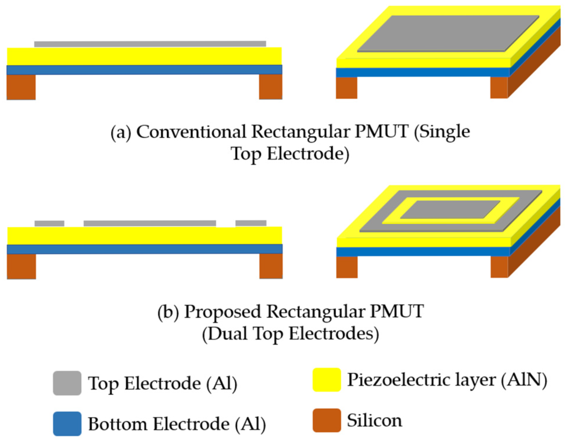
Figure 2.
FEA-simulated first four resonant mode shapes and their corresponding resonant frequencies for the conventional rectangular PMUT with single top electrodes.
Figure 2.
FEA-simulated first four resonant mode shapes and their corresponding resonant frequencies for the conventional rectangular PMUT with single top electrodes.
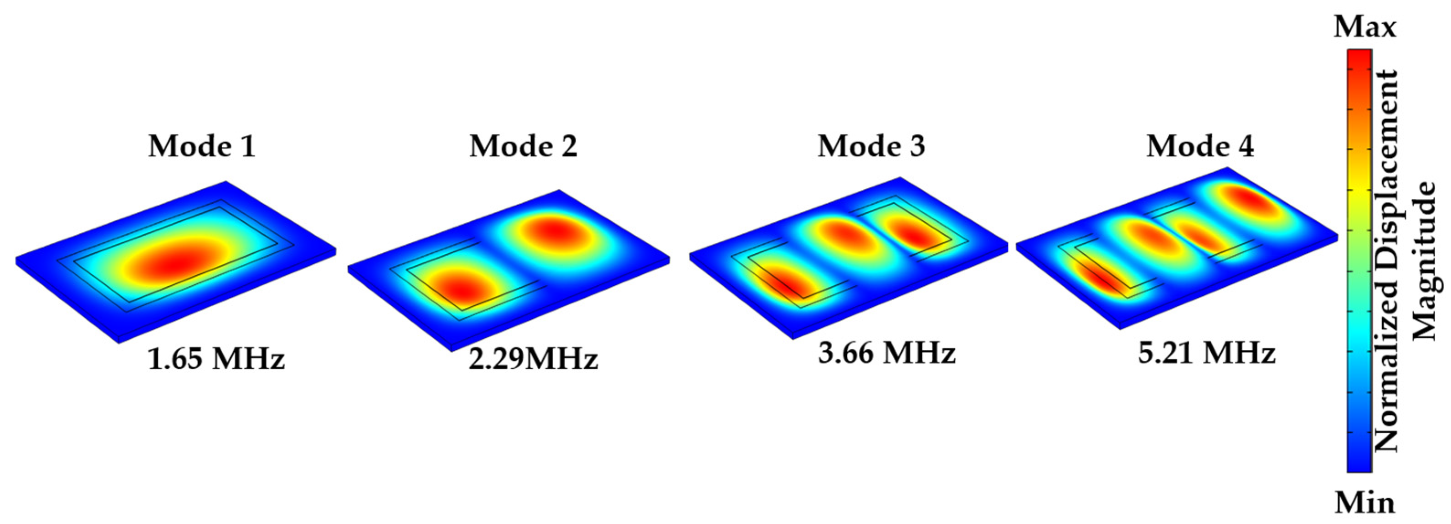
Figure 3.
FEA-simulated resonant mode shapes for Mode 1 and Mode 3 showing the configured electrode alignment with regions of maximum displacement for the proposed dual mode rectangular PMUT.
Figure 3.
FEA-simulated resonant mode shapes for Mode 1 and Mode 3 showing the configured electrode alignment with regions of maximum displacement for the proposed dual mode rectangular PMUT.
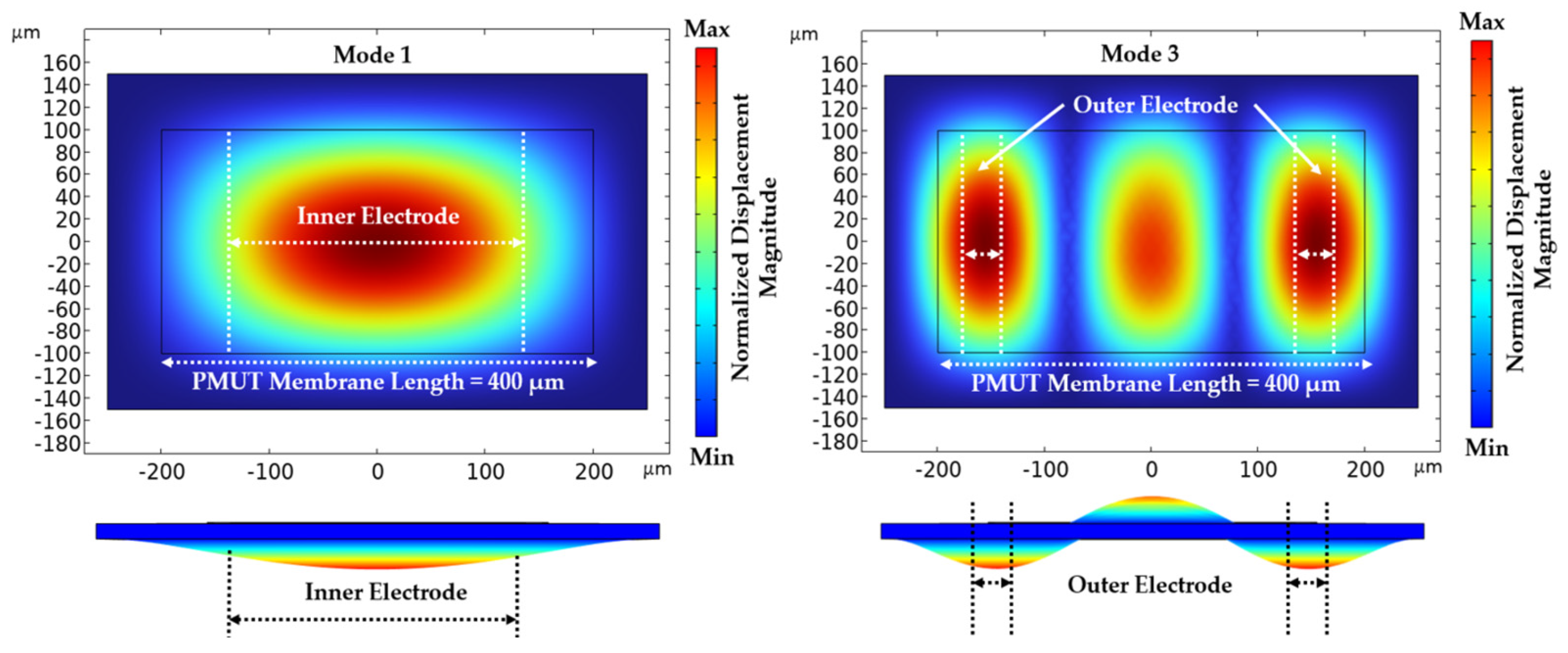
Figure 4.
FEA-simulated first four resonant mode shapes and their corresponding resonant frequencies for the proposed dual mode rectangular PMUT with dual top electrodes.
Figure 4.
FEA-simulated first four resonant mode shapes and their corresponding resonant frequencies for the proposed dual mode rectangular PMUT with dual top electrodes.
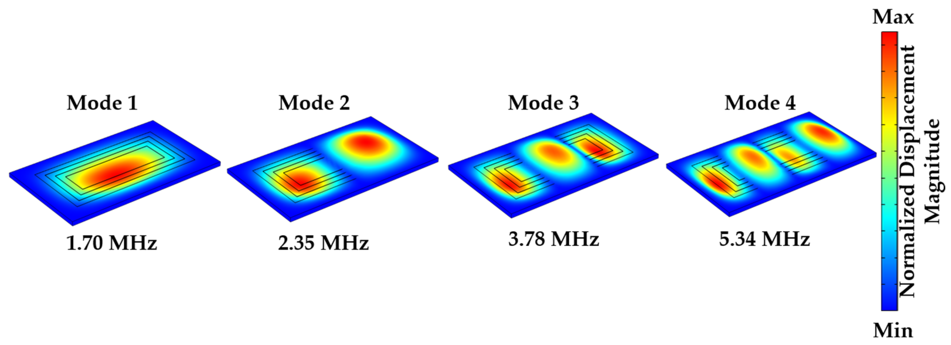
Figure 5.
FEA acoustic simulation of a single PMUT immersed in a water domain: (a) acoustic domain model showing the applied sound hard wall and spherical wave radiation boundary conditions, and (b) meshing applied to the acoustic domain.
Figure 5.
FEA acoustic simulation of a single PMUT immersed in a water domain: (a) acoustic domain model showing the applied sound hard wall and spherical wave radiation boundary conditions, and (b) meshing applied to the acoustic domain.
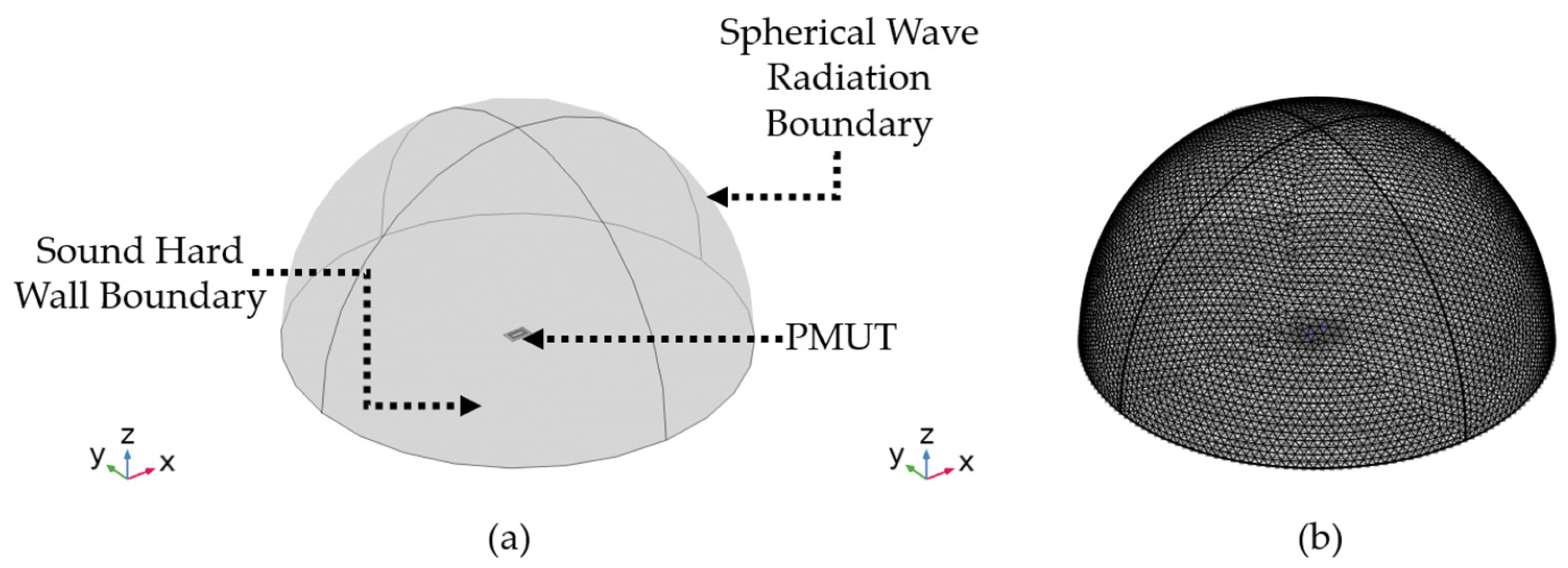
Figure 6.
Simulated acoustic intensity (W/m²) in water of the conventional rectangular PMUT with a single top electrode, showing the fundamental resonance at approximately 850 kHz and the higher-order resonance at 2.8 MHz.
Figure 6.
Simulated acoustic intensity (W/m²) in water of the conventional rectangular PMUT with a single top electrode, showing the fundamental resonance at approximately 850 kHz and the higher-order resonance at 2.8 MHz.
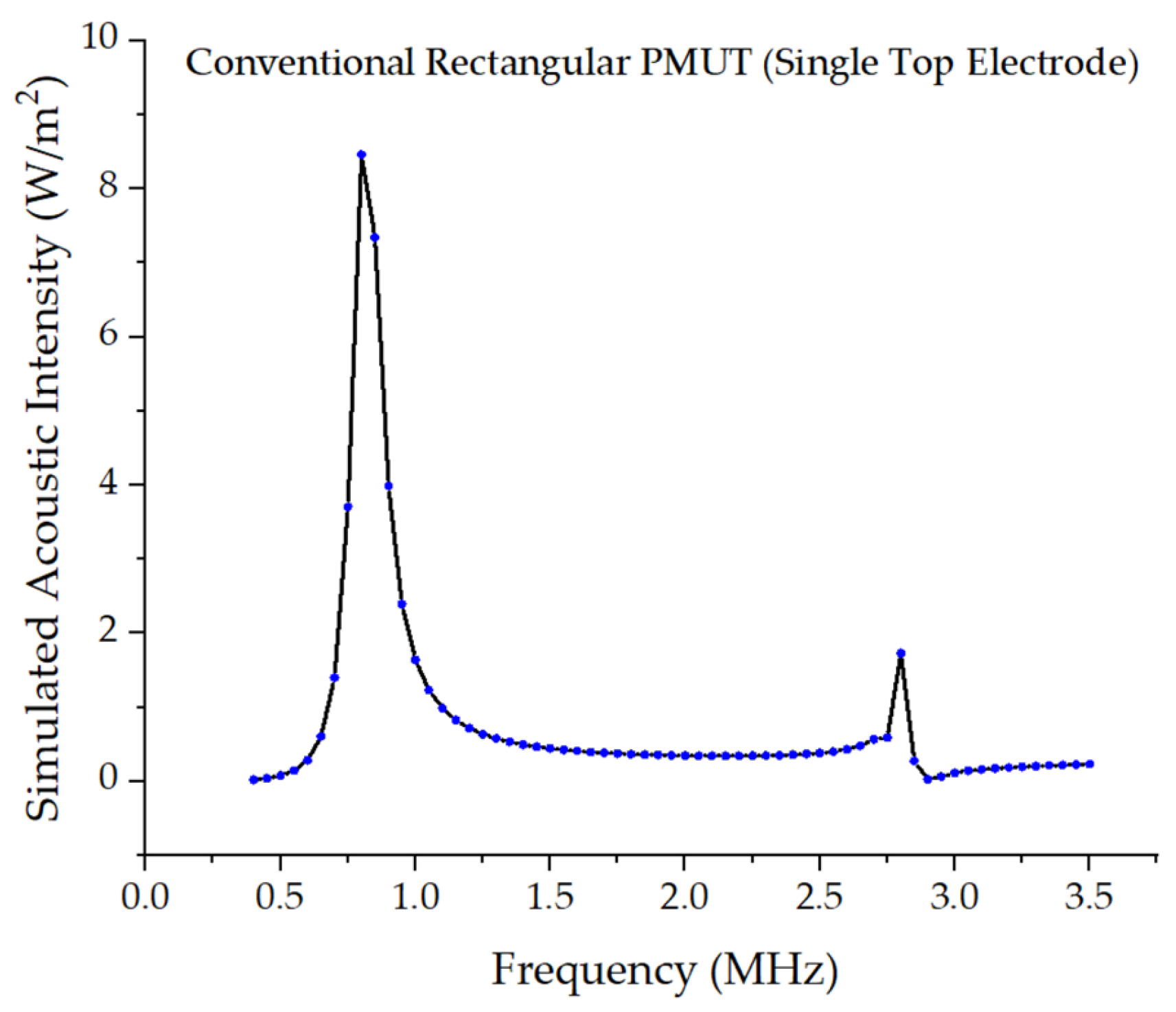
Figure 7.
Simulated acoustic intensity (W/m²) in water of the proposed dual mode rectangular PMUT under different electrode excitation conditions: (a) dual electrode excitation, (b) inner electrode excitation, and (c) outer electrode excitation. The results show that dual electrode actuation efficiently excites the fundamental resonance at approximately 850 kHz, while outer electrode actuation enhances the higher-order resonance near 2.8 MHz.
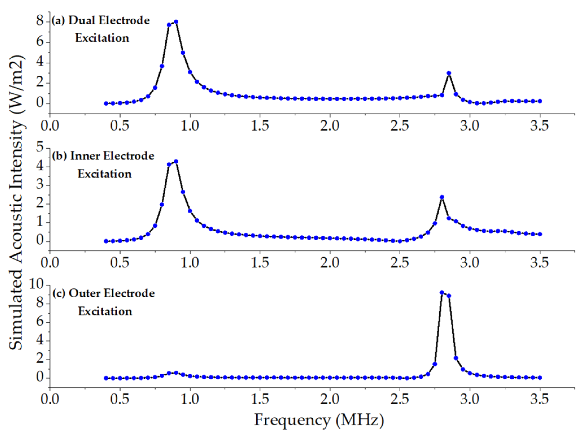
Figure 8.
Schematic illustration of the fabrication process for PMUT devices. (a) The process begins with a silicon-on-insulator (SOI) wafer comprising a silicon substrate, buried oxide, and device silicon layer. (b) A thin pad oxide layer is thermally grown and patterned for electrical isolation. (c) A piezoelectric aluminum nitride (AlN) layer is deposited and etched to define the active piezoelectric regions. (d) A metal stack (Cr/Al) is deposited and patterned to form electrical contacts and routing. (e) A protective polyimide layer is applied to safeguard the top side during backside processing. (f) Deep reactive ion etching (DRIE) is performed from the backside to remove the substrate and buried oxide, creating through-holes and releasing the membrane. (g) Finally, the protective layer is stripped, completing the fabrication of the suspended PMUT structures.
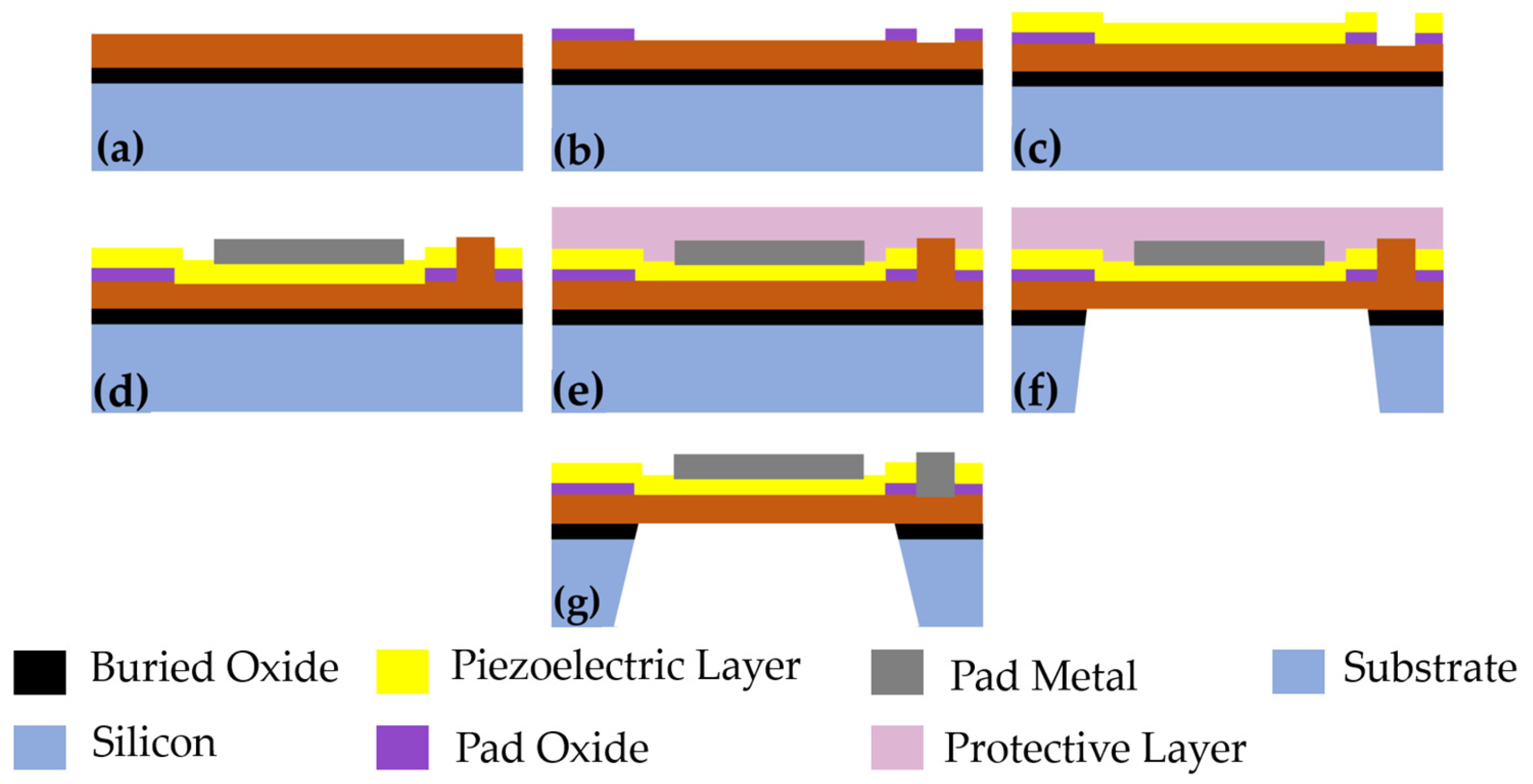
Figure 9.
Optical and scanning electron microscope (SEM) images of the fabricated rectangular PMUTs realized using the PiezoMUMPs process: (a) conventional single electrode rectangular PMUT and (b) proposed dual mode rectangular PMUT with dual top electrodes. The insets show the corresponding SEM micrographs of the released membranes, highlighting the electrode configurations and membrane definition.
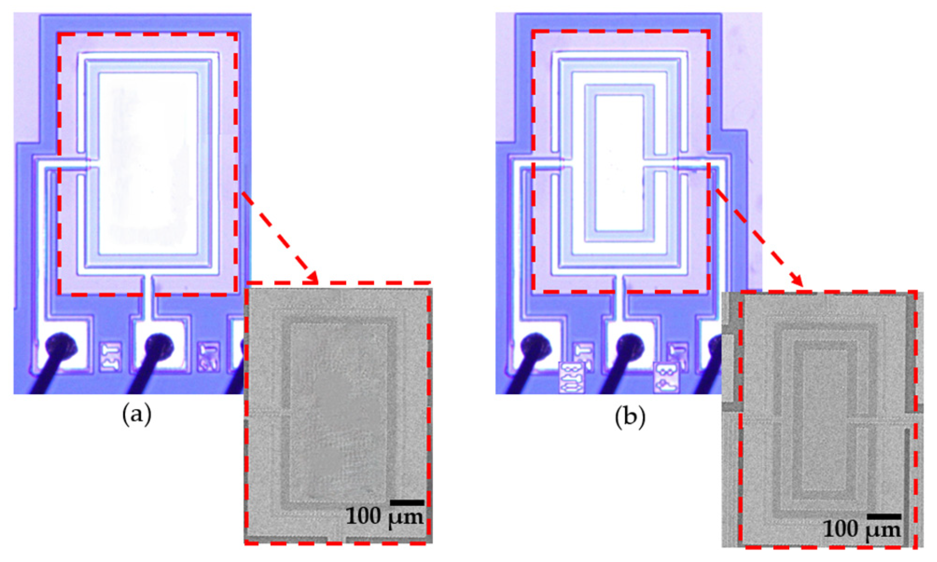
Figure 10.
Measured impedance magnitude and phase response of the conventional single-electrode rectangular PMUT showing the fundamental resonance (Mode 1) at 1.62 MHz and the higher-order resonance (Mode 3) at 3.78 MHz.
Figure 10.
Measured impedance magnitude and phase response of the conventional single-electrode rectangular PMUT showing the fundamental resonance (Mode 1) at 1.62 MHz and the higher-order resonance (Mode 3) at 3.78 MHz.
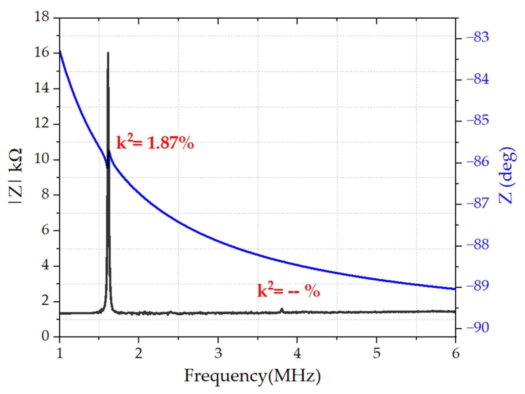
Figure 11.
Measured impedance magnitude and phase response of the proposed dual electrode rectangular PMUT showing the fundamental resonance (Mode 1) at 1.68 MHz and the higher-order resonance (Mode 3) at 3.89 MHz.
Figure 11.
Measured impedance magnitude and phase response of the proposed dual electrode rectangular PMUT showing the fundamental resonance (Mode 1) at 1.68 MHz and the higher-order resonance (Mode 3) at 3.89 MHz.
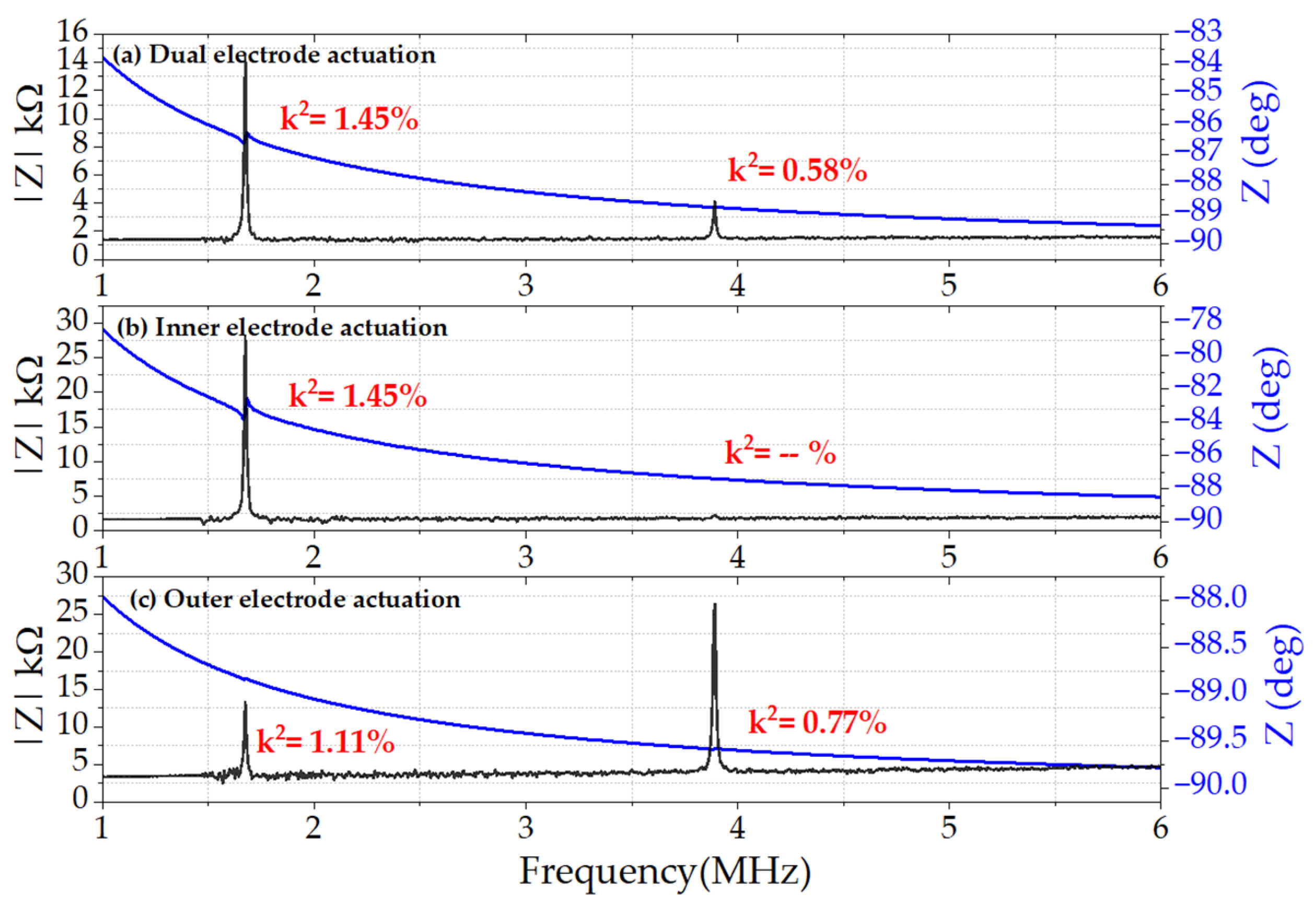
Figure 12.
Measured impedance magnitude and phase response of the conventional single-electrode rectangular PMUT underwater showing the fundamental resonance (Mode 1) at 800 kHz and the higher-order resonance (Mode 3) at 2.4 MHz.
Figure 12.
Measured impedance magnitude and phase response of the conventional single-electrode rectangular PMUT underwater showing the fundamental resonance (Mode 1) at 800 kHz and the higher-order resonance (Mode 3) at 2.4 MHz.
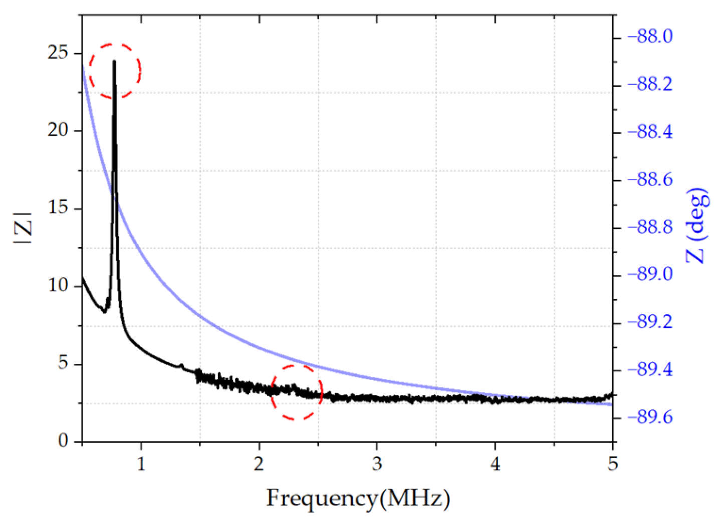
Figure 13.
Measured impedance magnitude and phase response of the proposed dual electrode rectangular PMUT underwater showing the fundamental resonance (Mode 1) at 800 kHz and the higher-order resonance (Mode 3) at 2.4 MHz.
Figure 13.
Measured impedance magnitude and phase response of the proposed dual electrode rectangular PMUT underwater showing the fundamental resonance (Mode 1) at 800 kHz and the higher-order resonance (Mode 3) at 2.4 MHz.
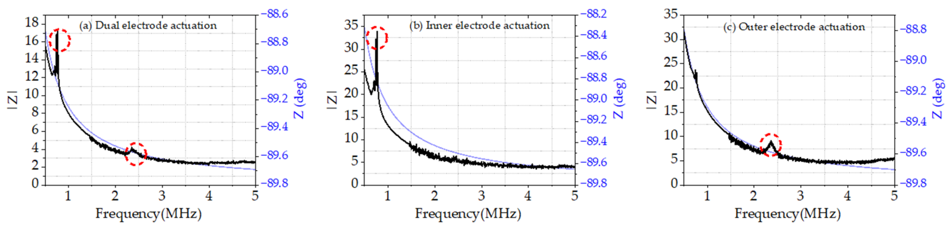
Figure 14.
Underwater acoustic characterization setup.
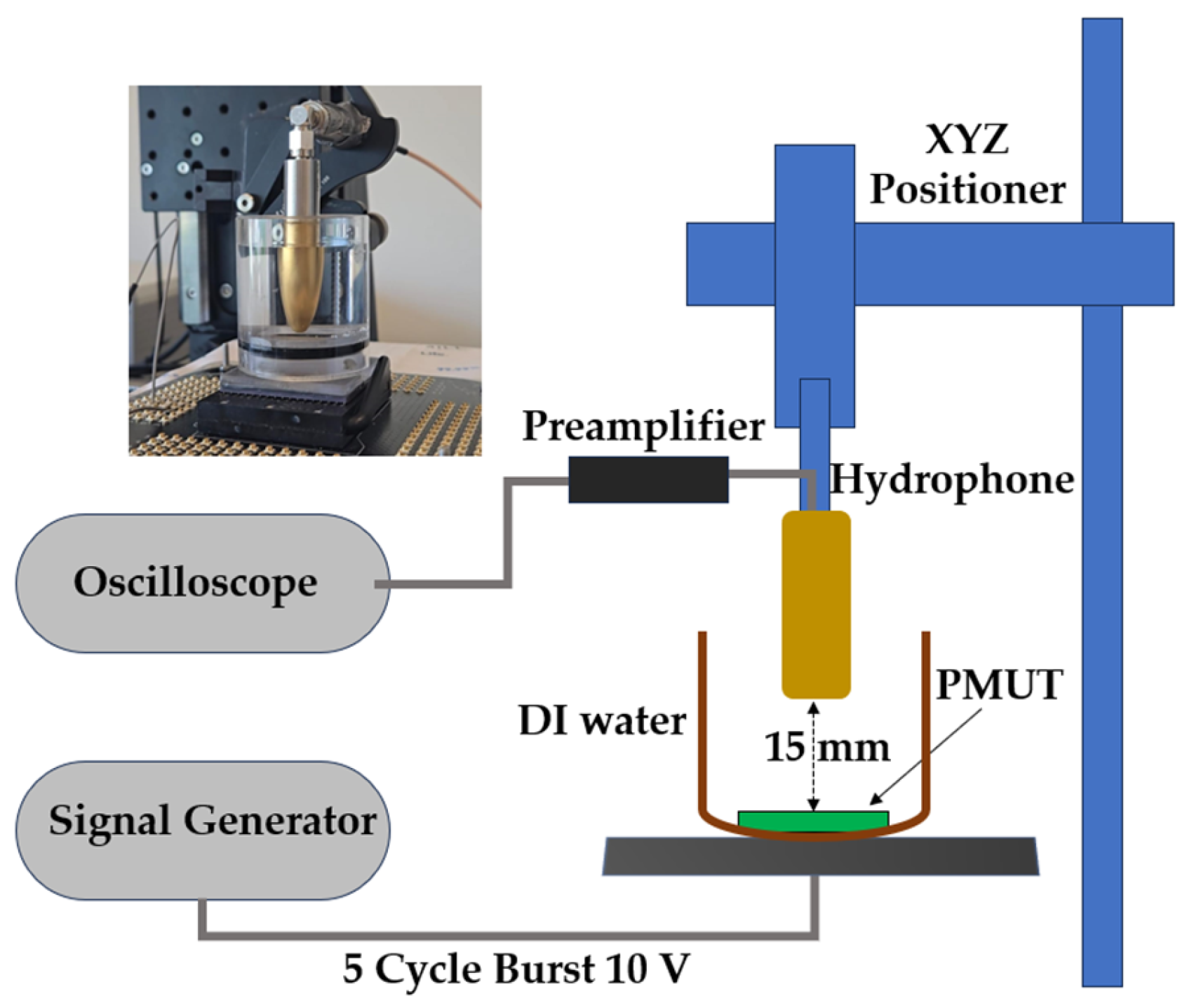
Figure 15.
Time-domain signal recorded on the oscilloscope, showing the hydrophone response to the acoustic wave transmitted by the PMUT. Initial electrical interference is followed by the acoustic signal, with the red dashed line marking the time-of-flight (ToF ≈ 10 μs). Inset: zoomed view of the acoustic waveform.
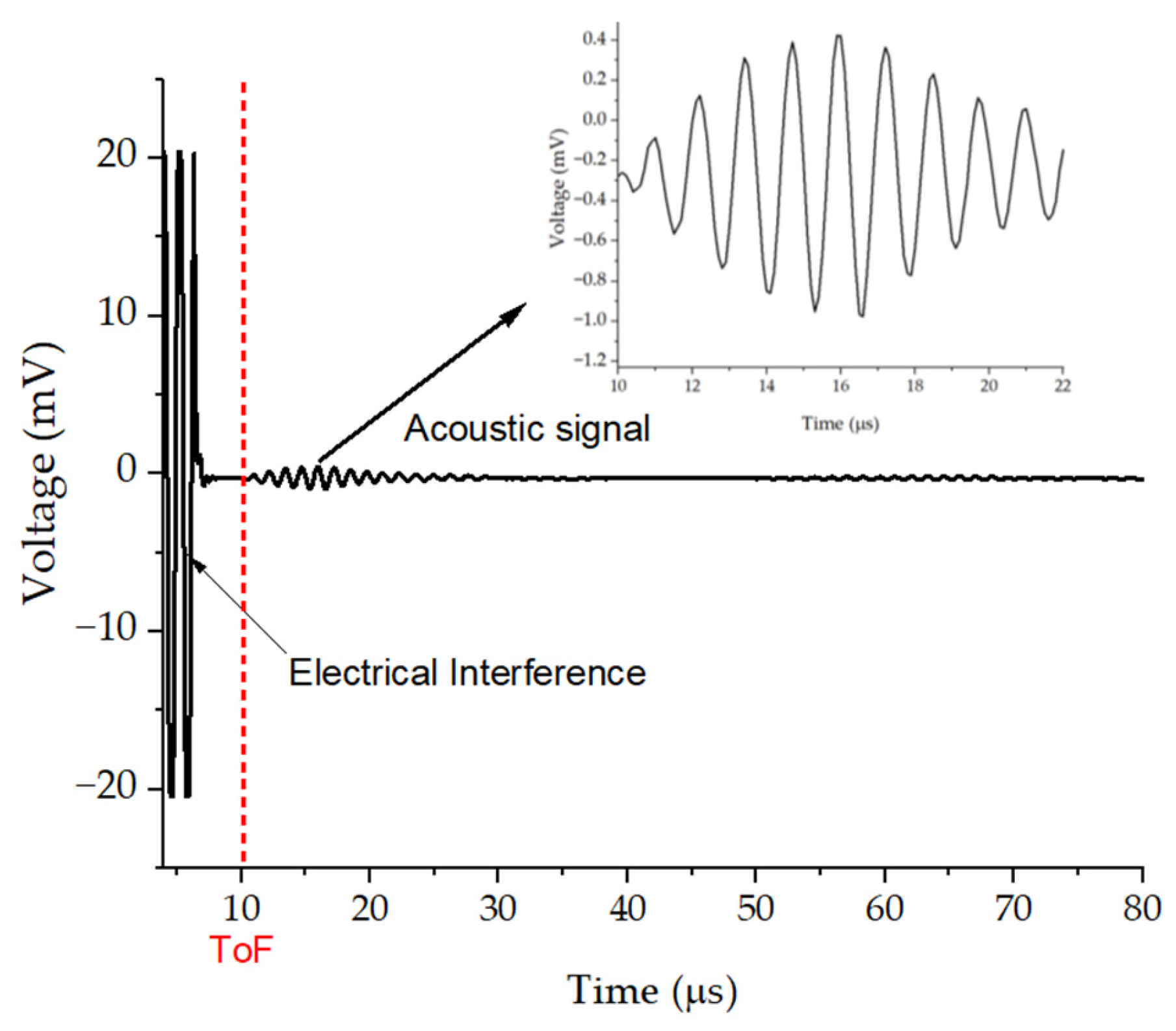
Figure 16.
Measured time-domain signal recorded on the oscilloscope and corresponding frequency spectrum at Mode 1 (800 kHz) for (a) the conventional PMUT and (b) the proposed dual-electrode rectangular PMUT.
Figure 16.
Measured time-domain signal recorded on the oscilloscope and corresponding frequency spectrum at Mode 1 (800 kHz) for (a) the conventional PMUT and (b) the proposed dual-electrode rectangular PMUT.
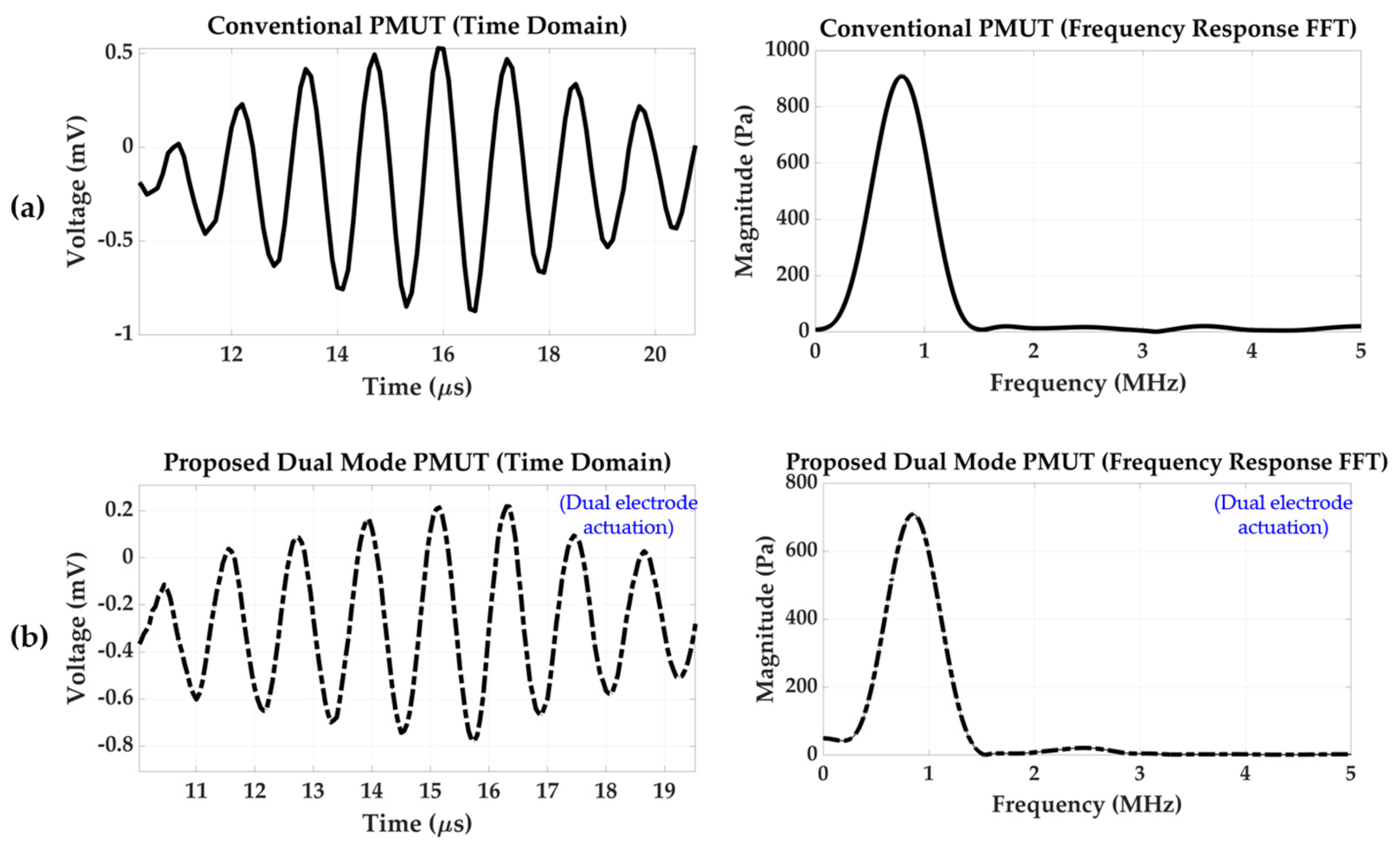
Figure 17.
Measured time-domain signal recorded on the oscilloscope and corresponding frequency spectrum at Mode 3 (2.5 MHz) for (a) the conventional PMUT and (b) the proposed dual-electrode rectangular PMUT.
Figure 17.
Measured time-domain signal recorded on the oscilloscope and corresponding frequency spectrum at Mode 3 (2.5 MHz) for (a) the conventional PMUT and (b) the proposed dual-electrode rectangular PMUT.
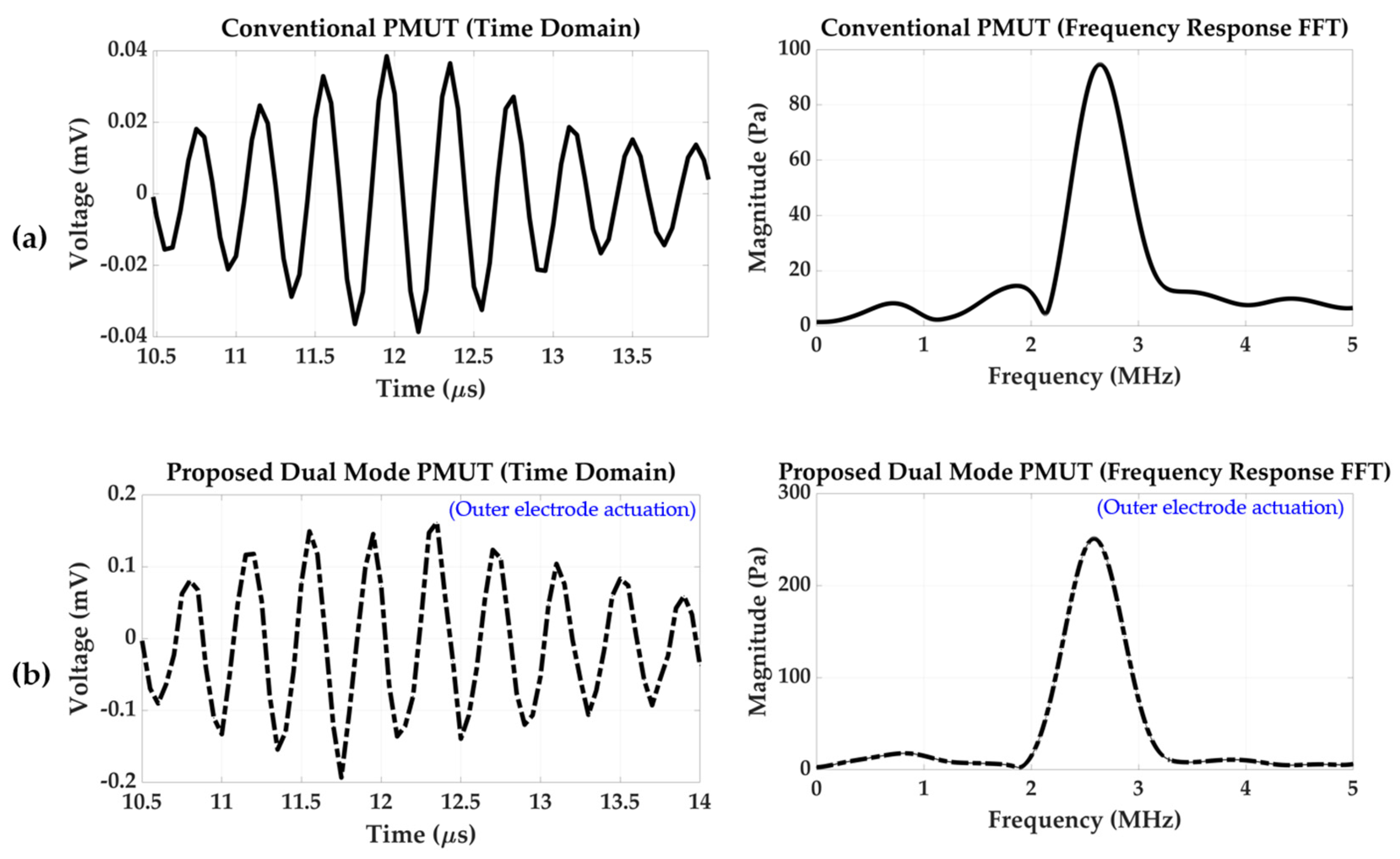

Table 1.
Electrode design parameters and membrane dimensions for conventional single-top-electrode and proposed dual-electrode rectangular PMUT configurations.
Table 1.
Electrode design parameters and membrane dimensions for conventional single-top-electrode and proposed dual-electrode rectangular PMUT configurations.
| PMUT Layers |
Material | Membrane Length (L) and Width (W) (μm) |
|
|---|---|---|---|
| Piezoelectric Layer | Aluminum Nitride (AlN) |
L x W = 400 x 200 | |
| Bottom Electrode |
Aluminum (Al) | L x W = 400 x 200 | |
| Top Electrode |
Aluminum (Al) | Single Top Electrode | L x W = 360 x 180 |
| Dual Top Electrode | Outer Electrode =L x W = (360 x 160) - (320 x 120) Inner Electrode =L x W = 280 x 80 |
||
| Device Layer |
Silicon (Si) |
L x W = 500 x 300 | |
| Trench | -- | L x W = 400 x 200 | |
Disclaimer/Publisher’s Note: The statements, opinions and data contained in all publications are solely those of the individual author(s) and contributor(s) and not of MDPI and/or the editor(s). MDPI and/or the editor(s) disclaim responsibility for any injury to people or property resulting from any ideas, methods, instructions or products referred to in the content. |
© 2025 by the authors. Licensee MDPI, Basel, Switzerland. This article is an open access article distributed under the terms and conditions of the Creative Commons Attribution (CC BY) license (http://creativecommons.org/licenses/by/4.0/).
Copyright: This open access article is published under a Creative Commons CC BY 4.0 license, which permit the free download, distribution, and reuse, provided that the author and preprint are cited in any reuse.


