
Submitted:
28 October 2025
Posted:
28 October 2025
You are already at the latest version
Abstract
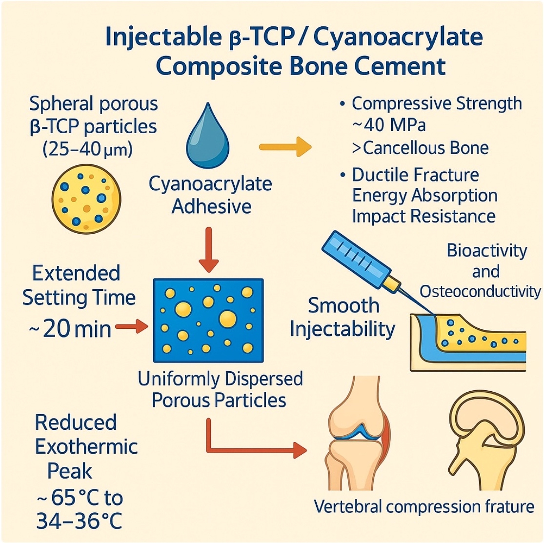
Bone cements based on polymethyl methacrylate (PMMA) remain the clinical standard for joint replacement and vertebral augmentation but suffer from several major challenges. These include excessive stiffness compared with cancellous bone, lack of resorption and osteoconductivity, and thermal necrosis during curing. Calcium phosphate cements (CPCs) are bioactive and resorbable but tend to exhibit low mechanical strength, poor injectability and brittle fracture. The work reported herein developed an injectable composite bone cement by combining spherical, porous, sintered β-tricalcium phosphate (β-TCP) particles with a cyanoacrylate adhesive. The β-TCP granules provided bioactivity and a favorable microarchitecture while the cyanoacrylate ensured strong adhesion and rapid setting. Ion substitution with Mg, Na and Si was found to modify the surface acidity of the material while also inhibiting cyanoacrylate polymerization, thereby extending the setting time and lowering the exotherm temperature. This composite exhibited high chemical stability, smooth injectability and early surface reactivity indicative of osteoconductivity. The compressive strength of the material stabilized at approximately 40 MPa and so exceeded that of cancellous bone. This new material also showed ductility, energy absorption and superior impact resistance, although its tensile and fatigue resistance remained limited. Importantly, the composite provided strength comparable to that of PMMA in cemented models during fixation tests and significantly outperformed CPCs in cementless tibial tray fixation experiments. These findings demonstrate that the present β-TCP/cyanoacrylate cement bridges the gap between PMMA and CPCs by combining injectability and mechanical reliability with bioactivity. This cement is therefore a promising next-generation option for minimally invasive osteoporotic fracture treatment and revision arthroplasty.
Keywords:
β-tricalcium phosphate
; cyanoacrylate adhesive
; injectable bone cement
; porous spherical sintered granules
; curing behavior
; mechanical properties
1. Introduction
Artificial joint replacement (AJR) is a well-established and effective therapeutic intervention for degenerative joint diseases such as osteoarthritis, rheumatoid arthritis and avascular necrosis of the femoral head, offering substantial improvements in pain relief and functional recovery [1]. Even so, the long-term outcomes of AJR often involve challenges related to complications that necessitate revision surgery. The major causes of revision surgery can be classified into five categories: (1) implant loosening due to aseptic osteolysis triggered by wear particles; (2) periprosthetic joint infection (PJI) resulting from bacterial colonization and biofilm formation; (3) implant dislocation or instability caused by malposition or soft tissue imbalance; (4) mechanical failure of implant components due to wear or breakage; and (5) periprosthetic fractures, particularly in elderly patients with compromised bone quality [2,3,4,5,6]. Revision surgery presents greater technical complexity than primary arthroplasty, as the former often involves managing extensive bone loss, infection or implant instability. Polymethyl methacrylate-based bone cement (PMMA-based BC) remains a fundamental component of fixation strategies, especially in cases involving poor bone quality or defects. Recent reviews and textbooks have examined the principles, techniques and outcomes of cemented arthroplasty [7,8,9,10]. Depending on the clinical scenario, revision procedures may require complete removal of the existing cement or re-cementation using the cement-in-cement technique. While the former offers improved bonding at the bone–cement interface, it is technically demanding. The latter allows for reduced operative time and minimized bone damage but may compromise fixation strength [11]. Cemented long stems are frequently used for femoral fixation during revision surgeries, regardless of whether the primary surgery was cemented or uncemented [12]. In the case of infection, antibiotic-loaded bone cement (ALBC), typically containing aminoglycosides or vancomycin, is employed to achieve local antimicrobial activity [13,14]. The increasing global prevalence of osteoporosis represents a major public health concern, particularly in aging populations. Osteoporosis is characterized by reduced bone mass and deterioration of the bone microarchitecture, resulting in decreased bone strength and an elevated risk of fracture [15]. An estimated 200 million individuals are affected worldwide, most of whom are postmenopausal women [16]. This trend underscores the urgent need for effective strategies to prevent and treat osteoporotic fractures, which have profound implications not only for individual quality of life but also for healthcare systems burdened by associated costs [17]. Among the various osteoporotic fractures, osteoporotic vertebral compression fractures (OVCFs) are especially prevalent and debilitating. OVCFs occur when weakened vertebral bodies collapse under physiological loading or minor trauma, leading to pain, spinal deformity and reduced mobility [18,19]. Although conservative treatments such as analgesics and spinal orthoses have traditionally been used, these approaches often fail to provide sufficient pain relief or prevent further fractures [20]. Consequently, minimally invasive procedures such as percutaneous vertebroplasty (PVP) and balloon kyphoplasty (BKP) have been widely adopted. These techniques involve the injection of bone cement into the affected vertebra to restore mechanical stability and facilitate early mobilization [21]. PMMA-based BC exhibits rapid polymerization, excellent moldability and established clinical performance, and so is the most widely used material in both PVP and BKP procedures [22]. However, several intrinsic limitations of PMMA-based BC compromise the long-term safety and effectiveness of this material. Firstly, the elastic modulus of PMMA (1700–3700 MPa) [23] is significantly higher than that of cancellous bone (10–900 MPa) [24], resulting in stress shielding and an increased risk of adjacent vertebral fractures. Secondly, PMMA is a non-resorbable material and so its presence can lead to interfacial gaps, fibrous encapsulation and inflammatory reactions over time [25]. Thirdly, the exothermic polymerization of this compound poses a risk of thermal injury to surrounding bone and neural tissue. Moreover, PMMA lacks osteoconductivity and biocompatibility, thereby limiting its capacity to promote new bone formation [26]. In response to these challenges, calcium phosphate cements (CPCs) have been developed as bioactive, resorbable alternatives to PMMA-based BC. CPCs, typically based on hydroxyapatite (HAp), brushite (dicalcium phosphate dihydrate, DCPD) or α/β-tricalcium phosphate (TCP), set via dissolution–precipitation reactions in aqueous environments to form a bone-like apatite phase [27,28]. These materials show exceptional biocompatibility and osteoconductivity and can also be resorbed and replaced by newly formed bone, all of which are highly desirable features promoting long-term integration [29]. Nevertheless, the relatively low mechanical strength, poor injectability and brittleness of these compounds limit their widespread use [30,31,32]. Recent review papers have emphasized the continuous development of injectable CPCs and bioactive composite cements, underscoring advances in polymer reinforcement, ion substitution and hybrid designs aimed at addressing problems related to brittleness and limited injectability [33,34]. At the same time, new biomaterial-based strategies have emerged that focus on modulating the bone microenvironment and enhancing biological responses in addition to mechanical fixation [35]. Based on these trends, the present study demonstrates a distinct approach that bridges the use of adhesive-based fixation and bioactive ceramics.
The present work demonstrates a novel composite BC comprising spherical, porous, sintered particles of β-tricalcium phosphate (β-TCP) combined with a cyanoacrylate adhesive. β-TCP is a resorbable calcium phosphate ceramic that provides a high degree of biocompatibility together with good osteoconductivity and is already widely used in clinical settings for bone regeneration. The use of spherical, porous β-TCP particles was expected to enhance cell infiltration and promote new bone formation by providing a favorable microarchitecture [36]. Cyanoacrylate is a medically-approved tissue adhesive that offers rapid curing, high adhesive strength and suitable tissue compatibility. The integration of this adhesive with β-TCP was intended to yield a hybrid material combining the injectability and mechanical reliability of the synthetic adhesive with the bioactivity and resorption ability of the calcium phosphate ceramic. The aim of this study was to develop and evaluate a new injectable BC based on the formulation described above. The physical, chemical and mechanical properties of the resulting composite, including setting behavior, compressive strength, chemical stability and injectability, were systematically investigated to assess its potential as an alternative to PMMA-based BC or CPCs in the treatment of osteoporotic fractures and in revision arthroplasty.
2. Materials and Methods
2.1. Synthesis and Sintering of Materials
2.1.1. Preparation of Raw Powder
The composition of the raw powder mixture is summarized in Table 1. The β-TCP was synthesized by mixing calcium carbonate (CaCO3; Fujifilm Wako Pure Chemical Corporation, Osaka, Japan) and ammonium hydrogen phosphate ((NH4)2HPO4; Fujifilm Wako Pure Chemical Corporation, Osaka, Japan) at a Ca/P molar ratio of 1.50. This mixture was subsequently wet-milled with alumina balls in ethanol for 48 h. After the ethanol was removed using a rotary evaporator, the precursor was sintered at 1100 °C for 3 h, employing heating and cooling rates of 5 °C/min. Mg-β-TCP specimens were prepared by substituting magnesium oxide (MgO) into the precursor composition, whereas MgNa-β-TCP/Si specimens were synthesized by incorporating MgO, sodium nitrate (NaNO3) and silicon dioxide (SiO2). The amounts of these dopants were adjusted to yield a (Ca + Na + Mg + □)/(P + Si) ratio of 1.571, where □ denotes a cation vacancy. The resulting mixtures were dried and sintered at 1130 °C for 3 h. The phases in the sintered powders were identified using X-ray diffraction (XRD, MiniFlex-600, Rigaku, Tokyo, Japan) while the functional groups in the specimens were analyzed using Fourier transform infrared spectroscopy (FT-IR, FT/IR-4X, JASCO, Tokyo, Japan). The sample microstructures were observed by scanning electron microscopy (SEM, JSM-7800, JEOL, Tokyo, Japan).
2.1.2. Preparation of Spherical Sintered Particles
Quantities of the sintered β-TCP, Mg9.0-β-TCP or MgNa-β-TCP/Si powders were pulverized in a mortar for 30 min. Each powder was then suspended in a 5 wt% polyvinyl alcohol (PVA; Fujifilm Wako) solution and processed using a spray dryer (LT-8, Okawara Chemical Machinery, Yokohama, Japan). The spray-drying parameters comprised an inlet temperature of 250 °C, outlet temperature of 100 °C, atomizer speed of 20,000 rpm and feed rate of 50 mL/min (Figure 1). The dried granules were subsequently sintered in rectangular alumina crucibles (120 × 40 mm) at 1100 °C (in the case of the β-TCP) or 1130 °C (in all other cases) for 48 h to obtain spherical, porous, sintered particles. The resulting structures were characterized by XRD (MiniFlex-600, Rigaku), FT-IR (FT/IR-4X, JASCO) and SEM (JSM-7800, JEOL).
2.2. Setting Tests
Mixtures of an ethyl cyanoacrylate adhesive (Aron Alpha 241, Toa Gosei, Nagoya, Japan) and the spherical sintered particles of β-TCP, Mg9.0-β-TCP or MgNa-β-TCP/Si were prepared at liquid-to-powder (L/P) ratios ranging from 0.7 to 1.0 mL/g at 23 ± 5 °C and a relative humidity below 75%. Mixing was performed inside a 5 mL syringe (SS-05SZ, Terumo, Tokyo, Japan) using a disposable stirrer (ART.00939-00, Kartell SpA, Italy) for 2 min. Each mixture was subsequently injected into a silicone tube (inner diameter 8 mm, height 20 mm). The curing behavior of each specimen was assessed by probing the surface with a Gilmore needle (B-001, JAPAN MECC, Tokyo, Japan) at 1 min intervals. The setting time was defined as the point at which the needle no longer penetrated the surface. The exotherm for each reaction was monitored using an infrared thermometer (IR-TE2, Chino, Tokyo, Japan). After curing, specimens were machined into cylinders (diameter 8 mm, height 10 mm) with parallel end surfaces in preparation for testing. The cured BC samples were evaluated using SEM (JSM-7800, JEOL) and electron probe microanalysis (EPMA; JXA-8800, JEOL).
2.3. Semi-Quantification of Acid Sites on Sintered Particles
Brønsted and Lewis acid sites on the surfaces of the various sintered particles were evaluated using FT-IR spectroscopy following pyridine adsorption. In each trial, a 1 g quantity of particles was immersed in pyridine (Fujifilm Wako) with stirring for 6 h at 23 ± 5 °C. Each sample was recovered by vacuum filtration, dried for 12 h and then analyzed. The intensities of the peaks at approximately 1500 cm-1 (related to pyridinium ions) and 1450 cm-1 (related to coordinated pyridine) in the resulting spectra were used to quantify Brønsted and Lewis acid sites based on comparisons to the C-H stretching peak at 2925 cm-1. The concentrations of surface acid groups were also assessed by dispersing 1 g of particles in 20 mL of ultrapure water with stirring for 10 min, following which the pH of the water was determined using a pH meter (F-54, Horiba, Tokyo, Japan).
2.4. Water Stability of BC Paste
Cured specimens were immersed in phosphate-buffered saline (PBS; Fujifilm Wako) at 37 °C for 14 days. The masses before (W0) and after (Wₐ) immersion were determined using an analytical balance having an accuracy of 0.1 mg while the percentage mass retained was calculated as (Wₐ/W0) × 100.
2.5. Mechanical Properties of Cured BC Specimens
Cured BC specimens were prepared by mixing the adhesive and particles at an L/P ratio of 0.7 mL/g for 90 s and then pouring the mixtures into fluorine resin molds. The molds were held at a temperature of 23 ± 5 °C and a relative humidity of 75% or less for 24 h before demolding. After removal, each specimen was immersed in a phosphate-buffered solution at 23 ± 5 °C for 96 to 168 h. Following immersion, each sample was dried at 23 ± 5 °C and a relative humidity of 75% or less for 16 to 24 h. To ensure that the surface condition of each specimen did not affect the test results, the samples were polished by grinding prior to assessment.
Figure 2 shows the dimensions and shapes of each type of test specimen. Tensile and compression tests were conducted using a uniaxial testing machine (AG-100kNXplus, Shimadzu Corporation, Kyoto, Japan) under static loading conditions with initial strain rates of 1×10⁻³ to 3×10⁻³ s-1. The elastic modulus was calculated using data from strain gauges attached to the specimen surfaces. Bending tests were conducted using a three-point bending method with a support distance of 15 mm and a crosshead speed of 0.02 mm/s. Torsion tests were performed using a torsion testing machine in conjunction with dumbbell-shaped test specimens made by machining cylindrical cured materials. For comparison purposes, test pieces were also prepared from commercially available bone fillers. It should be noted that tensile and fatigue test pieces made from this material were excluded from the comparative evaluation because these items were difficult to remove from the fluoroplastic molds. In addition, it was difficult to turn the torsion test pieces after molding with fluoroplastic, and so specimens made from the commercially available product could not be tested. A custom-made water bath was installed in a uniaxial testing machine to simulate a biological environment for fatigue testing, during which stress amplitude was applied with each specimen immersed in a phosphate buffer solution at 37 °C. For comparison purposes, evaluations were also conducted in air. The fatigue test conditions consisted of a stress ratio of R = -1 and a frequency of 5 to 10 Hz. A calibrated Charpy impact testing machine (MC-0.5P-1, Maekawa Testing Machine Mfg, Co., Ltd., Tokyo, Japan) was used to acquire fracture toughness data. This apparatus was equipped with a load sensor on the hammer, enabling evaluation of the impact force at the moment at which the hammer struck the test specimen. The support distance was set to 40 mm and the tests were conducted at 25 °C.
2.6. Implant Fixation and Bone Grafting Evaluation
Cell-type blocks of simulated bone manufactured from polyurethane by Avice, Inc. (Ibaraki, Japan) were used in this work. The ability of the BC to provide a suitable degree of bone filling in low-density autologous bone was assessed using simulated specimens with densities of 7.5 PCF (L), 12.5 PCF (M) and 20 PCF (H), as shown in Figure 3.
The simulated bone specimens were 60 mm in width, 60 mm in depth and 40 mm in height. The model implants each comprised an SUS304 stainless steel rod with a diameter of 16 mm, hard chrome plating and a surface roughness (Ra) of 0.12 μm. The relationship between the thickness of the BC application and fixation strength was investigated by drilling pilot holes into the simulated bone having diameters of 16.4, 16.8 or 17.2 mm, with a constant depth of 24 mm.
During fixation trials, the cement was first injected into the pilot hole in the simulated bone to a height of approximately 12 mm, followed by insertion of the implant. A packing ring and the associated retaining washer were then attached to the implant to prevent excessive leakage of the BC from the opening. The packing ring retaining force was approximately 2 kN while the implant insertion force was approximately 400 N. The fixation process was completed within 60 s from the start of cement injection. After fixation, the packing and retaining washer were removed. In some cases, the packing remained fixed to the upper surface of the simulated bone because a small amount of cement had flowed out from the opening. This was considered to have no effect on the test results and so the cement overflow was left as is (Figure 4(a)). Fixation strength was evaluated by clamping the simulated bone with a washer having an inner diameter of 46 mm and conducting a pull-out test of the implant using a bolt (Figure 4(b)). Based on observations of the fracture sites on each fixed body after the pull-out test that evaluated the cement penetration status, the degree of bone augmentation was determined.
2.7. Tibial Tray Fixation Strength Comparison
This study also compared the strength and fracture characteristics of actual tibial trays and simulated bones fixed using the BC combined with commercially available artificial bone. The tibial trays were fixed using cemented implants (Johnson & Johnson Attune RP artificial knee joint system, size 4) and cementless implants (Johnson & Johnson Attune cementless artificial knee joint system, size 4). The tibial trays used are shown in Figure 5.
Figure 6 provides diagrams of the simulated bone specimens used in this work. Prior to drilling, a gap was created by offsetting the implant by 0.8 mm and the artificial bone material was applied to this gap. It should be noted that the tibial tray used for cementless fixation is larger than autologous bone and is normally inserted with a slight interference fit. However, since the simulated bone lacked the flexibility of autologous bone, this technique could not be applied in the present work. Therefore, the same 0.8 mm gap was employed as had been used in trials with the cemented fixation units and the implant was fixed using the artificial bone material. In addition to the newly developed BC formulation, a widely used commercially available BC (referred to herein as the comparative BC) and a bone filler (referred to as the comparative bone filler) were also used as artificial bone materials. The fixation method employed when working with the tibial tray and the simulated bone involved first applying the artificial bone material (mixed according to the specified process) to the tibial tray, inserting the simulated bone, and immediately applying a compressive force of approximately 100 N for 300 s. The amount of artificial bone material applied was sufficient to fill the gaps completely and any excess material that overflowed after filling the gaps was removed before curing. Each fixed specimen was immersed in a phosphate-buffered solution for 96–168 h, during which time curing took place. Following this, the cured specimens were dried for at least 24 h at 23 ± 5 °C and 75% relative humidity before testing. Testing was performed by inserting an extraction punch from the back surface of the fixed body and pushing it out to simulate the removal of the implant from the simulated bone. This process was based on the method previously reported by Grupp et al. [37] and is illustrated in Figure 7.
3. Results and Discussion
3.1. Preparation of Raw Materials for BC
Figure 8 shows SEM images of the β-TCP powder synthesized via a solid-state reaction and having the composition summarized in Table 1. These images show irregularly-shaped particles with sizes ranging from 2 to 5 µm. After spray-drying and subsequent sintering, porous, spherical granules were obtained with sizes in the range of approximately 25–40 µm. These spherical particles exhibited significantly improved flowability and also showed better mixing efficiency and uniform reactivity when combined with the cyanoacrylate. The evident surface roughness of this material was also expected to enhance the adhesion between the particles and the cyanoacrylate.
Figure 9 shows XRD patterns for porous, spherical, sintered β-TCP, Mg9.0-β-TCP and NaMg-β-TCP/Si particles. All samples generated characteristic diffraction peaks corresponding to a β-TCP structure, with no evidence of secondary HAp or β-Ca2P2O7 phases. The peaks obtained from the Mg-substituted and Si-substituted samples were shifted to higher angles, suggesting that Si atoms were substituted at P(1) sites while Mg was substituted at Ca(5) sites and Na was incorporated into the Ca(4) vacancies for charge compensation. These structural changes were consistent with those observed in previous work by the authors [38].
The lattice constants for these samples are plotted as functions of the amount of SiO2 in Figure 10. The lattice parameters for the pure β-TCP were found to be a = 1.0435 nm and c = 3.7372 nm, in good agreement with constants previously reported by the authors [39]. In the case of the Mg-substituted β-TCP (in which 9.09 mol% of the Ca atoms at Ca(5) sites were replaced with Mg), the constants were a = 1.0341 nm and c = 3.7034 nm, consistent with data obtained from other studies [40]. Upon the additional substitution of Si at the P(1) sites, with Na added for charge compensation at the Ca(4) vacancies, increasing the Si content to 3 mol% of the total P caused the a-axis constant to slightly increase while the c-axis constant remained essentially unchanged. The absence of secondary phases and the systematic changes in the lattice constants indicated that these samples consisted of solid solutions based on the β-TCP crystal structure [41].
Figure 11 provides FT-IR spectra of the various specimens. The β-TCP generated characteristic peaks related to the vibrations of phosphate groups at 430 cm-1 (ν2), 540 and 600 cm-1 (ν4), and 940 and 970 cm-1 (ν1), as well as at 1030 and 1105 cm-1 (ν3) [42]. A peak at 3570 cm-1 related to -OH absorption and attributable to hydroxyapatite was not observed, nor was a P–O–P peak assignable to β-Ca2P2O7 and normally found at 727 cm-1. These results confirm that the β-TCP was present as a single phase. The FT-IR spectrum of the Mg9.0-β-TCP was essentially identical to that of the β-TCP, indicating that the substitution of Ca ions by Mg ions at the Ca(5) sites did not alter the fundamental phosphate vibrational modes. In contrast, the NaMg-β-TCP/Si spectrum exhibited distinct features attributable to the incorporation of SiO4 units at PO4 sites. In addition to the characteristic phosphate absorption peaks, this sample produced bands corresponding to the asymmetric stretching vibration (ν3) of Si–O at approximately 1080 cm-1 as well as the symmetric stretching vibration (ν1) of Si–O at 855, 875 and 900 cm-1 [38].
The β-TCP spectrum shows characteristic phosphate peaks while the NaMg-β-TCP/Si spectra display peaks related to Si–O vibrations at 855, 875, 900 and 1080 cm-1.
Figure 12 illustrates the β-TCP crystal structure. Figure 12(a) shows the atomic arrangement along the a-axis for a hexagonal setting. The β-TCP structure comprises linear A-columns (P(1)-Ca(4)-Ca(5)-P(1)-□(vacancy)-Ca(5)) with zigzag B-columns (P(2)-Ca(2)-Ca(1)-Ca(3)-P(3)-...) surrounding the A-columns to form tunnel-like structures [40]. In the Mg9.0-β-TCP, Mg2+ ions (having a radius of 0.065 nm and so smaller than Ca2+ ions with a radius of 0.099 nm) were substituted at Ca(5) sites in conjunction with octahedral coordination, leading to reductions in both the a and c lattice constants [37]. In the Si-substituted samples, Si4+ ions (0.041 nm) partially replaced P5+ ions (0.034 nm) at P(1) sites, with Na+ ions (0.095 nm) compensating for the charge at the underlying Ca(4) vacancies. These substitutions caused a slight expansion in the a-axis while leaving the c-axis nearly constant. These mechanisms by which Mg, Na and Si were substituted into the β-TCP are consistent with those in previous reports [36].
3.2. BC Setting Time and Peak Temperature
The setting time and peak exotherm temperature for the BC specimens prepared by mixing the aforementioned particles with the cyanoacrylate at L/P ratios of 0.7–0.9 mL/g are presented in Figure 13 and Figure 14.
Figure 13 summarizes the effects of the L/P ratio. In the case of the β-TCP-based particles, setting occurred within 3–7 min regardless of the cyanoacrylate content, with peak temperatures ranging from 60 to 65 °C. Cyanoacrylate generally polymerizes rapidly via an anionic mechanism. In this process, water molecules act as bases (OH-) that attack the electron-deficient double bond of the cyanoacrylate monomers, generating carbanions and propagating the chain polymerization [43,44]. To clarify the effect of the surface acidity of the particles on cyanoacrylate polymerization, BC mixtures incorporating Mg9.0-β-TCP and NaMg-β-TCP/Si were evaluated. When the Mg9.0-β-TCP was combined with the cyanoacrylate under identical conditions, the setting time was significantly increased, to approximately 60 min, while the peak temperature was decreased to an average of 38 °C. Increasing the cyanoacrylate proportion in the mixture further extended the setting time to approximately 100 min and reduced the exothermic peak temperature to approximately 36 °C. In the case of the NaMg-β-TCP/Si particles, the retardation effect was even more pronounced, with setting times extending from 85 to 120 min and peak temperatures in the range of 34–36 °C. These results confirm that the substitution of Mg, Na and Si into the β-TCP lattice effectively suppressed the exothermic polymerization of the cyanoacrylate, thereby extending the workable time while simultaneously reducing the reaction temperature [43,44]. Similar strategies have been reported with regard to other composite systems, such as magnesium phosphate cements combined with alginate hydrogels to regulate curing kinetics and improve clinical handling [45].
With the aim of achieving an optimal setting time on the order of 20 min, the fast- curing β-TCP and slow-curing NaMg-β-TCP/Si2.0 were combined (Figure 14). A 5:5 β-TCP:NaMg-β-TCP/Si2.0 mass ratio resulted in the desired setting time and maintained a relatively low peak temperature of 43.6 ± 2.0 °C. The setting time could also be tuned by changing the proportion of Si in the particles and varying the L/P ratio.
The surface acidities of the BC powders were further characterized by pyridine adsorption, with the results presented in Figure 15. The pure β-TCP was found to have negligible surface amounts of both Brønsted and Lewis acid sites. In contrast, the Mg9.0-β-TCP and NaMg-β-TCP/Si demonstrated marked increases in Brønsted acid site density that correlated with the extent of Si substitution. Moreover, immersion tests revealed a decrease in the pH of the supernatant following 10 min of stirring in deionized water. Taken together, these findings indicate that the suppression of cyanoacrylate polymerization that was observed can be ascribed to the presence of protons at Brønsted acid sites that effectively neutralized hydroxide ions derived from ambient moisture, thereby hindering the initiation of the anionic chain polymerization reaction [43,44].
3.3. BC Disintegration Resistance and Injectability
Figure 16 shows the resistance of the PC paste to disintegration in a saline solution. This prolonged immersion in physiological saline demonstrated that a paste comprising a β-TCP:NaMg-β-TCP/Si0.5 mixture with a 6:4 ratio and with an L/P ratio of 0.9 mL/g exhibited remarkably high resistance to disintegration, with a mass loss as low as 0.30 ± 0.12% after 336 h. This stability is of particular importance in clinical settings, where it is important to maintain cement integrity after the incorporation of the material in the body, so as to ensure mechanical support during the initial stages of bone regeneration.
In addition to stability, the BC paste exhibited excellent injectability and was found to readily extrude through a syringe while retaining its form upon contact with saline (Figure 17). The immediate formation of a superficial reaction layer indicated an early physicochemical interaction with the surrounding environment that could act as a precursor for osteoconductive behavior and subsequent integration with host bone tissue. This ability to deliver the paste in a minimally invasive manner while maintaining structural stability would be advantageous in the case of clinical applications to irregular bone defects or confined surgical fields. Compared with conventional PMMA-based BC formulations that tend not to demonstrate resorption or osteoconductivity and generate high exotherm temperatures, the present BC showed superior chemical stability, smooth injectability and inherent bioactivity derived from the β-TCP. Furthermore, unlike brittle CPCs with poor injectability and insufficient mechanical strength, this composite combined reliable compressive performance with favorable handling. These dual advantages suggest that this material could function as a next-generation alternative for minimally invasive bone repair and augmentation.
3.4. Curing Behavior of the Composite
FT-IR analysis of the internal cross sections of cured BC specimens at different time points revealed an increase in peaks corresponding to C≡N, C=O and C–H and a decrease in C=C peaks, confirming the progressive polymerization of the cyanoacrylate (Figure 18) [43,44].
The compressive strength of the specimens was found to increase along with this curing process (Figure 19). Specifically, the strength reached approximately 50% of the final value within 6 h, approximately 70% of this value after 24 h, and plateaued at approximately 40 MPa after 144 h. This final strength exceeded that of cancellous bone, indicating the ability of the material to provide reliable structural support. In a clinical setting, this gradual strength development would be advantageous as it would ensure sufficient workability during surgery while achieving stable fixation within the timeframe critical for initial bone healing. In contrast to the rapid but biologically inert curing of PMMA-based BC, the present system achieves a favorable balance of injectability, bioactivity and mechanical reliability.
Figure 20 presents SEM and EPMA images of the cured specimens. These images confirm that the sintered particles were uniformly dispersed within the cyanoacrylate matrix. The apparent density of these samples, as determined by the Archimedes principle, was 1.65 ± 0.13 g/cm3, corresponding to a porosity of 43–45%. This porosity is primarily attributable to the presence of the sintered particles. This porous architecture would be expected to promote a ductile fracture response under compression as well as bone ingrowth. Nevertheless, concerns regarding possible inflammatory responses or cytotoxicity from cyanoacrylate degradation products remain. Although the present in vitro results demonstrate favorable stability and compatibility, further in vivo investigations will be essential to clarify the long-term degradation behavior and confirm clinical safety. Elemental mapping of Ca by EPMA further verified the spatial distribution of these particles, consistent with the SEM findings. It should be noted that, in the case of samples fabricated with a high L/P ratio, the sintered particles exhibited a tendency to aggregate more densely within the matrix.
3.5. Mechanical Properties of Cured BC
The mechanical properties of the cured BC specimens were characterized by performing tensile, compression, three-point bending, torsion, fatigue and impact tests, with the stress–stroke relationships presented in Figure 21, Figure 22, Figure 23, Figure 24, Figure 25, Figure 26, Figure 27 and Figure 28. For comparison purposes, commercially available bone fillers were also examined by compression, bending and impact tests. The values determined for each of the mechanical properties are provided in Table 2. Examination of the tensile and compressive strengths reveals a marked asymmetry, in that the peak tensile stress was 10.2 MPa (n = 5) whereas the peak compressive stress reached 36.0 MPa, exceeding three times the tensile strength. This asymmetry is consistent with the general mechanical response of cementitious materials, in which stress concentration at internal pores under tensile loading promotes early crack initiation and brittle fracture. Despite exhibiting a compressive strength on the same order of magnitude as those of commercially available bone fillers, the BC was found to be marginally inferior and failed to satisfy the mechanical property requirements defined by ISO 5833 for PMMA-based bone cements [46]. In contrast to the brittle fracture observed under tensile loading, compression tests revealed ductile deformation, as evidenced by the gradual post-peak load decay. This behavior was substantially different from the abrupt stress drop seen in the case of a commercial bone filler comprising a calcium phosphate-based BC. This ductile response under compression suggests that the BC provides superior structural stability when subjected to compressive force (Figure 23). Comparable strategies to improve toughness have been demonstrated in work with hybrid CPC systems incorporating gelatin methacrylate and synthetic polymers [46]. Moreover, bioactive composites combining CPCs with bioglass or polymeric phases have shown enhanced mechanical reliability and biological performance [47]. These findings emphasize that the present β-TCP/cyanoacrylate system represents a distinct but complementary route to overcoming the inherent brittleness of conventional CPCs.
Based on the three-point bending tests, the peak bending strength of the present BC was approximately three times higher than that of a calcium phosphate-based BC. Bending involves the application of a compressive stress on the upper surface of the specimen with a simultaneous tensile stress on the lower surface, with the neutral axis acting as the transition boundary. Hence, the relatively low tensile strength of the BC likely affected fracture initiation, a phenomenon that has also been observed in studies with other porous ceramic–polymer composites [24]. Direct tensile testing of the commercial filler could not be performed due to difficulties in specimen preparation. However, the bending and compression results for this material suggest even poorer tensile properties than those of the newly developed BC, consistent with the general behavior of calcium phosphate-based cements [47]. The curvatures of the stress–strain profiles near the peak load also differed significantly between materials. The BC exhibited a convex curve, suggesting limited plastic deformation prior to fracture, while the commercial filler showed a linear, elastic-brittle response up to failure. This observation is consistent with the greater deformation capacity of the BC in response to compression and aligns with earlier studies that assessed the effects of microstructural connectivity and pore morphology on composite fracture behavior [47].
The torsion test produced a peak surface shear stress of 17.5 MPa that was compara ble to the shear strengths reported for adult cancellous bone (2-5 MPa) [47,48]. While this finding indicates that the BC approached the shear resistance of natural bone, further assessments based on a broader dataset will be required before drawing definitive conclusions. Shear strength is a critical parameter related to maintaining axial loads and preventing loosening during medical screw fixation. Although the present study does not specifically address the fixation characteristics of screws, the potential integration of medical screws with the BC assessed in this research represents a promising avenue for future research and clinical applications. Fatigue testing established that the BC could withstand repeated tensile–compressive cycling at ±3 MPa for 5 × 10⁶ cycles. This relatively low endurance limit under cyclic loading suggests that this material would be unsuitable for applications with sustained tensile fatigue stresses. However, in clinical uses where tensile loading is minimal, such as in tibial components of knee arthroplasty, this limitation may not be a concern. Robo et al. [49] reported that even a relatively low fatigue limit of approximately 3 to 5 MPa in low-modulus bone cement exceeds the physiological stress experienced by the spine during daily activities, suggesting the potential for clinical applications. Based on this finding, the present BC may similarly be considered a promising candidate for use as a low-stress artificial bone material in clinical settings.
Impact testing provided further insights into the fracture mechanics of this material. The load–time profile obtained from the BC showed two distinct load peaks, with the delay between hammer contact and the second peak being longer than that of the commercial filler. From these data, it appears that crack propagation after the initial fracture was slower in the BC and that the energy absorption capacity of the material was greater. These findings are consistent with the hypothesis that ductility under compression contributes to impact resistance [50]. The fracture patterns also differed markedly between the materials. The BC typically fractured into two pieces with cracks initiating at both the hammer and fulcrum points, whereas the commercial filler fractured into four pieces with cracks predominantly originating from the fulcrum. In this work, the pilot hole in a synthetic bone model designed for cementless fixation was intentionally enlarged to simulate a segmental bone defect. This void was subsequently filled with the BC to secure the tibial tray as a means of demonstrating the potential clinical applications of this BC as a defect-filling material in orthopedic implant fixation [51].
Taken together, these results show that the BC exhibited higher ductility and an en- hanced energy absorption capacity under compression compared with the conventional bone filler. Even so, the tensile and fatigue properties of the former would limit its use in certain applications. This combination of properties may make the present BC formulation a promising candidate for load-bearing applications dominated by compressive stress, provided that the tensile limitations are accounted for in design and surgical planning.
3.6. Pull-out Strengths of Implant–Bone Complexes Fabricated using Simulated Bone Blocks
The pull-out strength for implant–bone complexes (hereafter referred to as “complexes”) fabricated using simulated bone blocks having a density of 20 PCF (H) was 4.70, 5.27 and 4.23 kN, in order of increasing pilot hole diameters. The complexes with a density of 12.5 PCF (M) had values of 4.26, 4.25 and 4.53 kN. In the case of the 7.5 PCF (L) simulated bone specimens, the large pore volume limited the strength that could be obtained when the same amount of BC was applied as had been used with the higher density bone samples. This occurred due to insufficient infiltration and a lower contact area. The maximum pull-out strength in such cases after optimizing increases in the BC mass was 1.59 kN. Notably, increasing the pilot hole diameter—equivalent to increasing the applied BC thickness—did not result in a significant change in strength. From this finding, it is evident that a thicker BC layer could potentially be used to fill irregular defects without compromising fixation performance.
The appearance of representative post-test specimens is shown in Figure 29. Nine da tasets were acquired for each density level, revealing distinct fracture patterns. In trials using the low-density simulated bone, failure frequently occurred at the BC–implant interface whereas, in the case of the higher-density bone, fractures tended to occur either within the bone structure itself or at the interface between BC-infiltrated and non-infiltrated regions. Nevertheless, no substantial difference in peak strength was observed among the samples exhibiting different failure modes, suggesting that the mechanical strength at the implant–bone cement interface was comparable to that of the simulated bone material.
The causes of the strength variations were examined by preparing simulated bone models based on replacing the metallic implant rods with PTFE rods of identical dimensions. This modification enabled X-ray computed tomography (CT) observations of the penetration of the BC into the porous structures. The CT images in Figure 30 demonstrate that the BC in the 7.5 PCF bone exhibited greater outflow through the large pores yet still filled the pores. Nevertheless, regions were observed at the implant–bone interface where the extent of BC infiltration was excessive, resulting in areas of reduced BC–implant contact. This finding suggests that the reduction in fixation strength can be attributed not to the fracture pattern itself but rather to diminished interfacial adhesion between the BC and the cylinder. This lower adhesion, in turn, resulted from capillary-driven BC outflow into the surrounding porous matrix.
Because the low-density specimens showed fewer instances of internal fracture while some failures occurred within the simulated bone itself, the intrinsic strength of the bone analogue was also examined. Simulated bone blocks were cut into cross-sections having dimensions of 25 × 25 mm with a height of 40 mm, after which steel flanges were bonded to each end using an epoxy adhesive. The tensile strength of these specimens was then ascertained by pulling the flanges in opposite directions. As shown in Figure 31, internal fractures occurred in all density types. The tensile stress calculated from the peak load divided by the external cross-sectional area (neglecting porosity) for each sample type is provided in Figure 32. The 7.5 PCF (L) bone exhibited a markedly lower tensile strength compared with the 12.5 (M) and 20 PCF (H) samples.
These findings suggest that the markedly lower fixation strength observed in trials using the 7.5 PCF simulated bone during the pull-out test of the rod-shaped implant model corresponds to a similar trend in the intrinsic strength of the simulated bone itself. This implies that the fixation site in this simulated bone was not in a critically weakened condition compared with those in the higher-density specimens. Conversely, considering that approximately one-third of the failures in the pull-out test of the rod-shaped implant model occurred within the simulated bone itself, it can be inferred that the fixation strength was comparable to the intrinsic strength of the bone. From this equivalence, it appears that the fixation site was not structurally deficient. Hence, this technology could be applied in clinical scenarios involving low-density autologous bone, such as in the treatment of osteoporotic conditions. Although some cases of BC–implant interfacial debonding were observed in the 7.5 and 12.5 PCF specimens, it is anticipated that adjusting the applied volume of BC such that the capillary-driven outflow capacity is exceeded could improve interfacial bonding. Such findings agree with previous studies reporting that an optimal adhesive volume and suitable pore-filling behavior are critical with regard to achieving stable implant fixation in low-density cancellous bone [52]. A two-step application process could be the best approach to regulating capillary forces at the interface. In this process, the low viscosity of the BC could be initially used to facilitate effective pore filling, followed by a secondary application that leverages the adhesive properties of the BC to achieve secure implant fixation. This approach could potentially provide fixation strengths exceeding those observed in the present study, and thus represents a promising avenue for future research.
3.7. Comparison of Fixation Strength in Tibial Tray–Simulated Bone Complexes Using Vari ous Bone Substitute Materials
The fixation of implants was evaluated in both cemented and cementless tibial tray– simulated bone complexes, as shown in Figure 33. In the cemented configuration, fixation with the newly developed BC resulted in two distinct fracture patterns: complete fracture within the simulated bone or a combination of internal fracture with debonding at the BC–tibial tray interface. In contrast, fixation with the commercially available PMMA-based BC primarily resulted in internal fracture within the simulated bone, with minimal interfacial debonding. As shown in Figure 34, the mean peak load for the PMMA-based BC was higher than that for the BC, in agreement with the observed fracture modes. The fixation strength obtained from the BC was approximately 71% of that achieved with the PMMA-based BC. This difference can be attributed to the superior cohesive and adhesive properties of the latter material in cemented arthroplasty applications [23,26].
Similar trends were observed in trials using the cementless configuration. As shown in Figure 35, fixation with the BC produced both internal fracture within the simulated bone and interfacial debonding, either between the BC and the implant or between the BC and the simulated bone. In the case of the commercially available bone substitute, internal fracture within the simulated bone was limited to the central boss of the tibial tray and the small region encircled by the four smaller bosses. Outside this region, all failures occurred at the fixation interface or within the bone substitute material itself. Notably, a comparison of the peak loads established that the BC provided approximately twice the fixation strength of the commercially available bone substitute (Figure 36). In addition to mechanical fixation, bioactive degradable composite cements integrating calcium silicate or phosphate phases have been reported to promote both osteoconductivity and gradual resorption [53]. Similarly, functional composites embedding bioactive glass have demonstrated tunable antibiotic release profiles while maintaining mechanical integrity [54]. Such approaches highlight potential avenues for expanding the functionality of β-TCP/cyanoacrylate systems in the future.
These results indicate that, while the BC provided lower fixation strength than the PMMA in cemented applications, its performance in the cementless configuration surpassed that of conventional bone substitute materials. Based on its initial fixation strength, this BC could have applications as a novel bone substitute in cementless total knee arthroplasty. By intentionally enlarging the pilot hole in a synthetic bone model designed for cementless fixation to simulate a segmental bone defect, and subsequently filling the void with BC to secure the tibial tray, this study demonstrates the potential clinical applicability of the BC as a defect-filling material for orthopedic implant fixation. The combination of adequate interfacial adhesion and structural support provided by this newly developed formulation suggests potential clinical benefits, particularly in scenarios where cementless fixation is desired to avoid cement-related complications [55,56,57,58].
4. Conclusions
This work produced a novel injectable composite BC composed of spherical, porous particles of sintered β-TCP combined with a cyanoacrylate adhesive. The originality of this work lies in combining the bioactivity and resorption capacity of β-TCP with the strong adhesion and rapid curing of a cyanoacrylate. The substitution of Mg, Na and Si into this material effectively modulated the cyanoacrylate polymerization to extend the setting time and reduce the exotherm temperature. The resulting composite exhibited smooth injectability, high chemical stability and compressive strength exceeding that of cancellous bone, together with ductility, energy absorption and impact resistance. These features represent clear advantages over PMMA-based bone cements, which lack bioactivity and generate thermal risks. This material is also superior to CPCs, which suffer from brittleness and poor injectability. However, the tensile and fatigue properties of the present BC remain insufficient for high-stress applications, and concerns about potential inflammatory responses to cyanoacrylate degradation products must be addressed. Future studies should focus on long-term in vivo degradation, bone substitution capacity and safety evaluations in animal models. Addressing these challenges will be essential to establishing the clinical applicability of β-TCP/cyanoacrylate composites as next-generation bone cements for minimally invasive fracture treatment and revision arthroplasty.
Author Contributions
K.H., T.M., S.F. and S.T. initiated this project. S.A, I.T, S.K., T.K, T.M and S.F. conducted experiments and collected data. K.H. drafted the paper. K.H. and S.K wrote the paper and produced all the figures and tables. All authors participated in the discussion and interpretation of the results. All authors edited and proofread the final manuscript. All authors have read and agreed to the published version of the manuscript.
Funding
This work was supported by METI Monozukuri R&D Support Grant Program for SMEs (Grant Number JPJ005698), Japan.
Institutional Review Board Statement
Not applicable.
Informed Consent Statement
Not applicable.
Data Availability Statement
Not applicable.
Acknowledgments
The spray dryer used in this study was provided by the Chiba Ceram- ics Co., Ltd. and the cyanoacrylate was provided by the Toa Gosei Co., Ltd. The authors thank FORTE Science Communications for English language editing.
Conflicts of Interest
The authors declare no conflict of interest.
References
- Learmonth, I.D.; Young, C.; Rorabeck, C. The operation of the century: total hip replacement. Lancet 2007, 370, 1508–1519. [Google Scholar] [CrossRef] [PubMed]
- Bozic, KJ; Kurtz, SM; Lau, E; Ong, K; Chiu, V; Vail, TP; et al. The epidemiology of revision total hip arthroplasty in the United States. J Bone Joint Surg Am. 2009, 91, 128–33. [Google Scholar] [CrossRef]
- Goodman, S.B.; Gallo, J. Periprosthetic Osteolysis: Mechanisms, Prevention and Treatment. J. Clin. Med. 2019, 8, 2091. [Google Scholar] [CrossRef]
- Tande, AJ; Patel, R. Prosthetic joint infection. Clin Microbiol Rev. 2014, 27, 302–45.
- Berry, DJ. Epidemiology: hip and knee. Orthop Clin North Am. 1999, 30, 183–90. [Google Scholar] [CrossRef]
- Abdel, M.P.; Berry, D.J. Current Practice Trends in Primary Hip and Knee Arthroplasties Among Members of the American Association of Hip and Knee Surgeons: A Long-Term Update. J. Arthroplast. 2019, 34, S24–S27. [Google Scholar] [CrossRef]
- Satalich, J; Samuelsen, BT; Tuminelli, FJ; Emara, AK; Molloy, RM. Cementation in total hip arthroplasty: history, principles, techniques, and outcomes. J Orthop. 2022, 31, 94–101. [Google Scholar]
- Emara, AK; Satalich, J; Klika, AK; Krebs, VE; Molloy, RM. Femoral stem cementation in hip arthroplasty. Arthroplast Today. 2021, 9, 165–70. [Google Scholar] [CrossRef]
- Giebel, G; Wähnert, D; Schmidutz, F; Flörkemeier, T; Fensky, F; Pumberger, M; et al. The cemented stem in hip arthroplasty—state of the art. EFORT Open Rev. 2024, 9, 584–94. [Google Scholar]
- Sardar, I. Cemented total hip arthroplasty. In: Haidukewych G, Berry DJ, editors. Complex Primary Total Hip Arthroplasty. Cham: Springer, 2024. p. 123–36.
- Hanzlik, JA; Day, JS; Klein, GR; Levine, HB; McGuire, K; Mont, MA. Cement-in-cement revision of total hip replacement: a review. Hip Int. 2010, 20, 293–303. [Google Scholar]
- A Gie, G.; Linder, L.; Ling, R.S.; Simon, J.P.; Slooff, T.J.; Timperley, A.J. Impacted cancellous allografts and cement for revision total hip arthroplasty. J Bone Joint Surg Br. 1993, 75, 14–21. [Google Scholar] [CrossRef]
- Wahlig, H.; Dingeldein, E.; Bergmann, R.; Reuss, K. The release of gentamicin from polymethylmethacrylate beads. An experimental and pharmacokinetic study. J. Bone Jt. Surgery. Br. Vol. 1978, 60-B, 270–275. [Google Scholar] [CrossRef]
- Moojen, D.J.F.; Hentenaar, B.; Vogely, H.C.; Verbout, A.J.; Castelein, R.M.; Dhert, W.J. In Vitro Release of Antibiotics from Commercial PMMA Beads and Articulating Hip Spacers. J. Arthroplast. 2008, 23, 1152–1156. [Google Scholar] [CrossRef]
- Kanis, J.A. Diagnosis of osteoporosis and assessment of fracture risk. Lancet 2002, 359, 1929–1936. [Google Scholar] [CrossRef] [PubMed]
- Reginster, J.-Y.; Burlet, N. Osteoporosis: A still increasing prevalence. Bone 2006, 38, 4–9. [Google Scholar] [CrossRef] [PubMed]
- Hernlund, E.; Svedbom, A.; Ivergard, M.; Compston, J.; Cooper, C.; Stenmark, J.; McCloskey, E.V.; Jonsson, B.; Kanis, J.A. Osteoporosis in the European Union: Medical management, epidemiology and economic Burden: A report prepared in collaboration with the International Osteoporosis Foundation (IOF) and the European Federation of Pharmaceutical Industry Associations (EFPIA). Arch. Osteoporos. 2013, 8, 136. [Google Scholar] [CrossRef]
- Lindsay, R.; Silverman, S.L.; Cooper, C.; Hanley, D.A.; Barton, I.; Broy, S.B.; Licata, A.; Benhamou, L.; Geusens, P.; Flowers, K.; et al. Risk of New Vertebral Fracture in the Year Following a Fracture. JAMA 2001, 285, 320–323. [Google Scholar] [CrossRef]
- Ismail, A.A.; Pye, S.R.; Cockerill, W.C.; Lunt, M.; Silman, A.J.; Reeve, J.; Banzer, D.; Benevolenskaya, L.I.; Bhalla, A.; Armas, J.B.; et al. Incidence of Limb Fracture across Europe: Results from the European Prospective Osteoporosis Study (EPOS). Osteoporos. Int. 2002, 13, 565–571. [Google Scholar] [CrossRef]
- Klazen, C.A.; Lohle, P.N.; de Vries, J.; Jansen, F.H.; Tielbeek, A.V.; Blonk, M.C.; Venmans, A.; van Rooij, W.J.J.; Schoemaker, M.C.; Juttmann, J.R.; et al. Vertebroplasty versus conservative treatment in acute osteoporotic vertebral compression fractures (Vertos II): an open-label randomised trial. Lancet 2010, 376, 1085–1092. [Google Scholar] [CrossRef]
- Garfin, SR; Yuan, HA; Reiley, MA. New technologies in spine: kyphoplasty and vertebroplasty for the treatment of painful osteoporotic compression fractures. Spine 2001, 26, 1511–5. [Google Scholar] [CrossRef] [PubMed]
- Lewis, G. Injectable bone cements for use in vertebroplasty and kyphoplasty: state-of-the-art review. J Biomed Mater Res B Appl Biomater. 2006, 76, 456–68. [Google Scholar] [CrossRef]
- Kühn, KD. Bone Cements: Up-to-Date Comparison of Physical and Chemical Properties of Commercial Materials. Berlin: Springer, 2012.
- Rho, J.Y.; Ashman, R.B.; Turner, C.H. Young's modulus of trabecular and cortical bone material: Ultrasonic and microtensile measurements. J. Biomech. 1993, 26, 111–119. [Google Scholar] [CrossRef]
- Lewis, G. Properties of acrylic bone cement: State of the art review. J. Biomed. Mater. Res. 1997, 38, 155–182. [Google Scholar] [CrossRef]
- Webb, J.C.J.; Spencer, R.F. The role of polymethylmethacrylate bone cement in modern orthopaedic surgery. J. Bone Jt. Surgery. Br. Vol. 2027, 89-B, 851–857. [Google Scholar] [CrossRef]
- Constantz, B.R.; Ison, I.C.; Fulmer, M.T.; Poser, R.D.; Smith, S.T.; VanWagoner, M.; Ross, J.; Goldstein, S.A.; Jupiter, J.B.; Rosenthal, D.I. Skeletal Repair by in Situ Formation of the Mineral Phase of Bone. Science 1995, 267, 1796–1799. [Google Scholar] [CrossRef]
- Bohner, M. Calcium orthophosphates in medicine: from ceramics to calcium phosphate cements. Injury 2000, 31, D37–D47. [Google Scholar] [CrossRef] [PubMed]
- Dorozhkin, S.V. Calcium orthophosphate cements for biomedical application. J. Mater. Sci. 2008, 43, 3028–3057. [Google Scholar] [CrossRef]
- Ginebra, M.-P.; Canal, C.; Espanol, M.; Pastorino, D.; Montufar, E.B. Calcium phosphate cements as drug delivery materials. Adv. Drug Deliv. Rev. 2012, 64, 1090–1110. [Google Scholar] [CrossRef] [PubMed]
- Chow, L.; Takagi, S. A natural bone cement - A laboratory novelty led to the development of revolutionary new biomaterials. J. Res. Natl. Inst. Stand. Technol. 2001, 106, 1029–33. [Google Scholar] [CrossRef]
- Ginebra, M.P.; Rilliard, A.; Elvira, C.; Planell, J.A.; Fernández, E.; Román, J.S. Mechanical and rheological improvement of a calcium phosphate cement by the addition of a polymeric drug. J. Biomed. Mater. Res. 2001, 57, 113–118. [Google Scholar] [CrossRef]
- Wang, X; Ye, J; Wang, Y. Advances in the modification of injectable calcium phosphate cements. Biomater Sci. 2020, 8, 5614–30. [Google Scholar]
- Wong, TM; Yeung, KWK; Luk, KD; Cheung, KM. A review on the enhancement of calcium phosphate cements. J Orthop Translat. 2021, 30, 1–12. [Google Scholar]
- Jiang, Y; Liu, C; Zhang, X; et al. Biomaterial-based strategies for bone cement: modulating the bone microenvironment and promoting regeneration. J Nanobiotechnol. 2025, 23, 63. [Google Scholar]
- Kamitakahara, M.; Ohtsuki, C.; Miyazaki, T. Review Paper: Behavior of Ceramic Biomaterials Derived from Tricalcium Phosphate in Physiological Condition. J. Biomater. Appl. 2008, 23, 197–212. [Google Scholar] [CrossRef]
- Grupp, T.M.; Schilling, C.; Schwiesau, J.; Pfaff, A.; Altermann, B.; Mihalko, W.M. Tibial Implant Fixation Behavior in Total Knee Arthroplasty: A Study With Five Different Bone Cements. J. Arthroplast. 2020, 35, 579–587. [Google Scholar] [CrossRef]
- Hashimoto, K; Imai, T; Shibata, H. Preparation of silicon-substituted beta-tricalcium phosphate by the polymerized complex method. Phosphorus Res Bull. 2023, 39, 14–22. [Google Scholar] [CrossRef]
- Dickens, B.; Schroeder, L.; Brown, W. Crystallographic studies of the role of Mg as a stabilizing impurity in β-Ca3(PO4)2. The crystal structure of pure β-Ca3(PO4)2. J. Solid State Chem. 1974, 10, 232–248. [Google Scholar] [CrossRef]
- Massit, A; Fathi, M; Elyacoubi, A; Kholtei, A; El Idrissi, BC. Structural properties analysis of Mg-β-TCP by X-ray powder diffraction with Rietveld refinement. Lett Appl NanoBioSci. 2020, 9, 1562–8. [Google Scholar] [CrossRef]
- Yashima, M.; Sakai, A.; Kamiyama, T.; Hoshikawa, A. Crystal structure analysis of β-tricalcium phosphate Ca3(PO4)2 by neutron powder diffraction. J. Solid State Chem. 2003, 175, 272–277. [Google Scholar] [CrossRef]
- Jillavenkatesa, A; Condrate, RA Sr. The infrared and Raman spectra of β- and α-tricalcium phosphate (Ca3(PO4)2). Spectrosc Lett. 1998, 31, 1619–40. [Google Scholar] [CrossRef]
- Raja, P.R. Cyanoacrylate Adhesives: A Critical Review. Rev. Adhes. Adhes. 2016, 4, 398–416. [Google Scholar] [CrossRef]
- Klemarczyk, P; Guthrie, J. Advances in anaerobic and cyanoacrylate adhesives. Int J Adhes Adhes. 2010, 30, 183–93. [Google Scholar]
- Wekwejt, M; Zima, A; Świeczko-Żurek, B; et al. Injectable bone cement based on magnesium potassium phosphate and cross-linked alginate hydrogel. Sci Rep. 2024, 14, 13521. [Google Scholar]
- International Organization for Standardization. Implants for surgery—Acrylic resin cements. ISO 5833:2002(E). Geneva: ISO, 2002.
- Augat, P; Claes, L. Mechanical characteristics of bone and bone substitute materials. Injury. 2006, 37, S31–5. [Google Scholar]
- Moritz, N; Jokinen, J; Mattila, R; Areva, S; Peltola, T; Rahiala, H; et al. Compressive strength and porosity of calcium phosphate cements mixed with different liquids. J Biomed Mater Res B Appl Biomater. 2013, 101, 1240–6. [Google Scholar] [CrossRef]
- Robo, C; Öhman-Mägi, C; Persson, C. Fatigue behaviour of low-modulus bone cements under cyclic loading. J Mech Behav Biomed Mater. 2021, 123, 104764. [Google Scholar]
- Anderson, TL. Fracture Mechanics: Fundamentals and Applications. 4th ed. Boca Raton: CRC Press, 2017.
- Matsushita, Y; Ito, M; Kubo, T; et al. Influence of bone mineral density on fixation strength of cemented implants in cancellous bone. J Orthop Res. 2000, 18, 619–24. [Google Scholar]
- Park, JW; Ko, YM; et al. Injectable calcium phosphate bone cement for orthopedic use. J Orthop Res. 2020, 38, 312–21. [Google Scholar]
- Peng, Z; Chen, Y; Liu, J; et al. A bioactive degradable composite bone cement based on chitosan/magnesium phosphate/calcium silicate. Materials 2024, 17, 1861. [Google Scholar]
- Abd El-Hamid, AM; Mahmoud, A; Taha, MA; et al. Regulation of the antibiotic elution profile from tricalcium phosphate bone cement by addition of bioactive glass. Sci Rep. 2024, 14, 23119. [Google Scholar]
- Lombardi, AV Jr; Berend, KR; Walter, CA; et al. Is cementless total knee arthroplasty durable? A comparative study of cementless and cemented fixation. J Arthroplasty. 2011, 26, 17–20. [Google Scholar]
- Bugbee, WD; Ammeen, DJ. Fixation options in total knee arthroplasty. J Knee Surg. 2008, 21, 117–26. [Google Scholar]
- Toksvig-Larsen, S; Ryd, L; Lindstrand, A. Fixation of total knee arthroplasties: A comparison between cemented and uncemented fixation. J Arthroplasty. 1995, 10, 217–22. [Google Scholar]
- Ries, MD; Pruitt, L. PMMA cemented vs cementless fixation in TKA. Clin Orthop Relat Res. 2005, 440, 131–6. [Google Scholar]
Figure 1.
Schematic diagram of spray-drying equipment used to prepare spherical, porous granules.
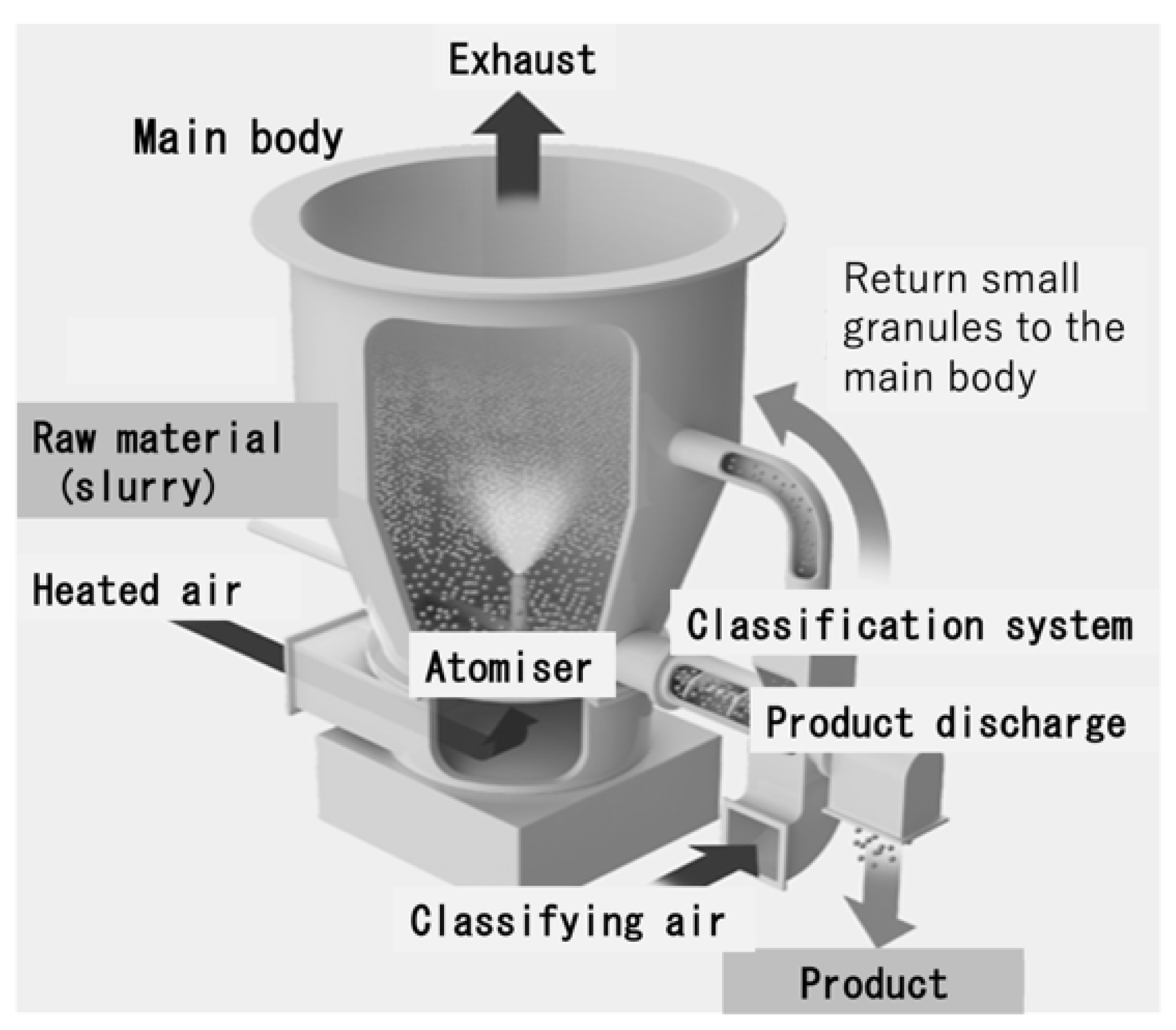
Figure 2.
Dimensions and shapes of test specimens used in tensile, compressive, bending, torsion, fatigue and impact tests.
Figure 2.
Dimensions and shapes of test specimens used in tensile, compressive, bending, torsion, fatigue and impact tests.
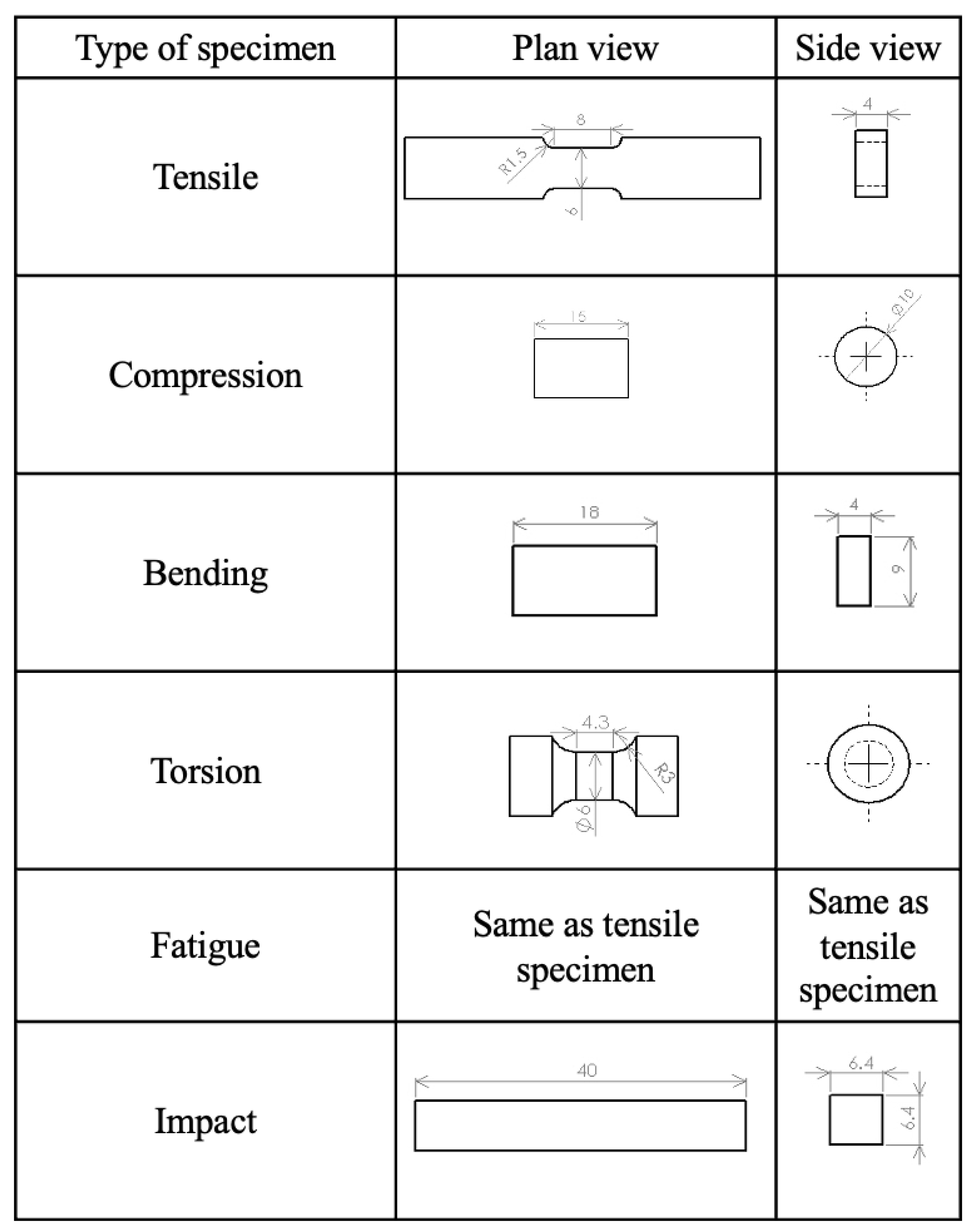
Figure 3.
Simulated bone blocks having densities of 7.5, 12.5 and 20 PCF with pilot holes.
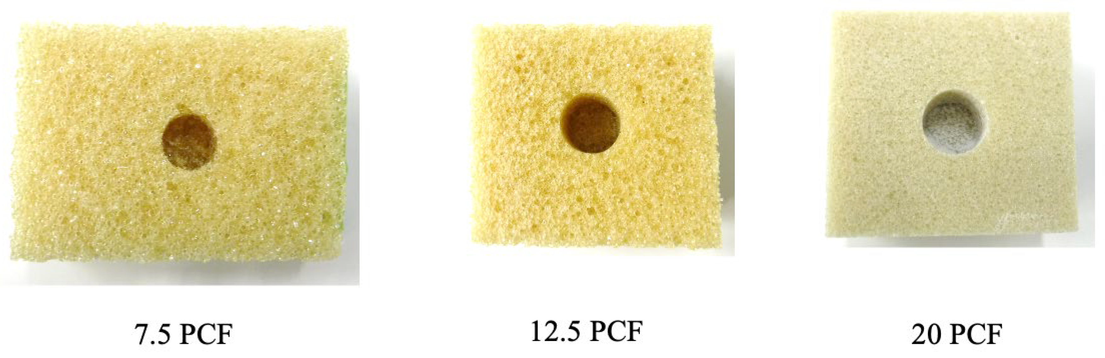
Figure 4.
Schematics of fixture made from polyurethane foam to hold implant, showing (a) external view and (b) cross-sectional view including the cement filling.
Figure 4.
Schematics of fixture made from polyurethane foam to hold implant, showing (a) external view and (b) cross-sectional view including the cement filling.
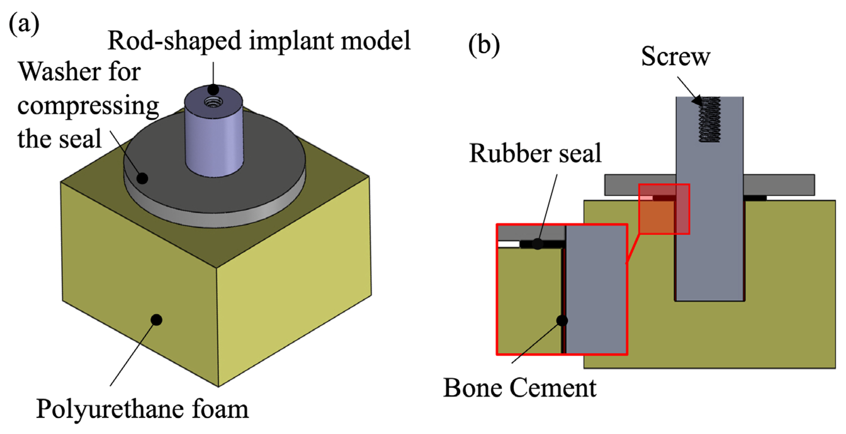
Figure 5.
Photographic images of the (a) cemented and (b) cementless tibial trays used in this work.
Figure 5.
Photographic images of the (a) cemented and (b) cementless tibial trays used in this work.
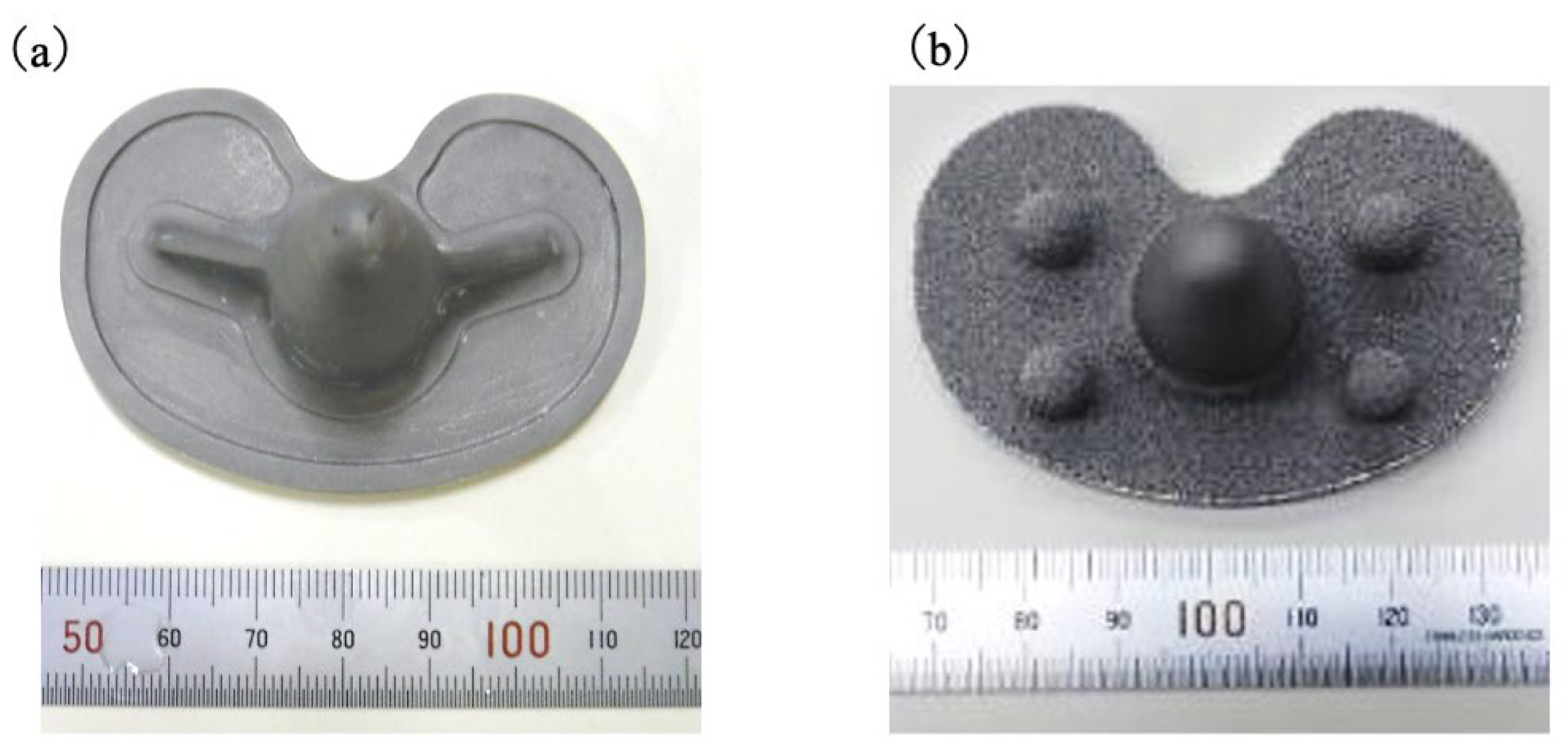
Figure 6.
Schematic diagrams of (a) cemented and (b) cementless simulated bone specimens with pilot holes.
Figure 6.
Schematic diagrams of (a) cemented and (b) cementless simulated bone specimens with pilot holes.
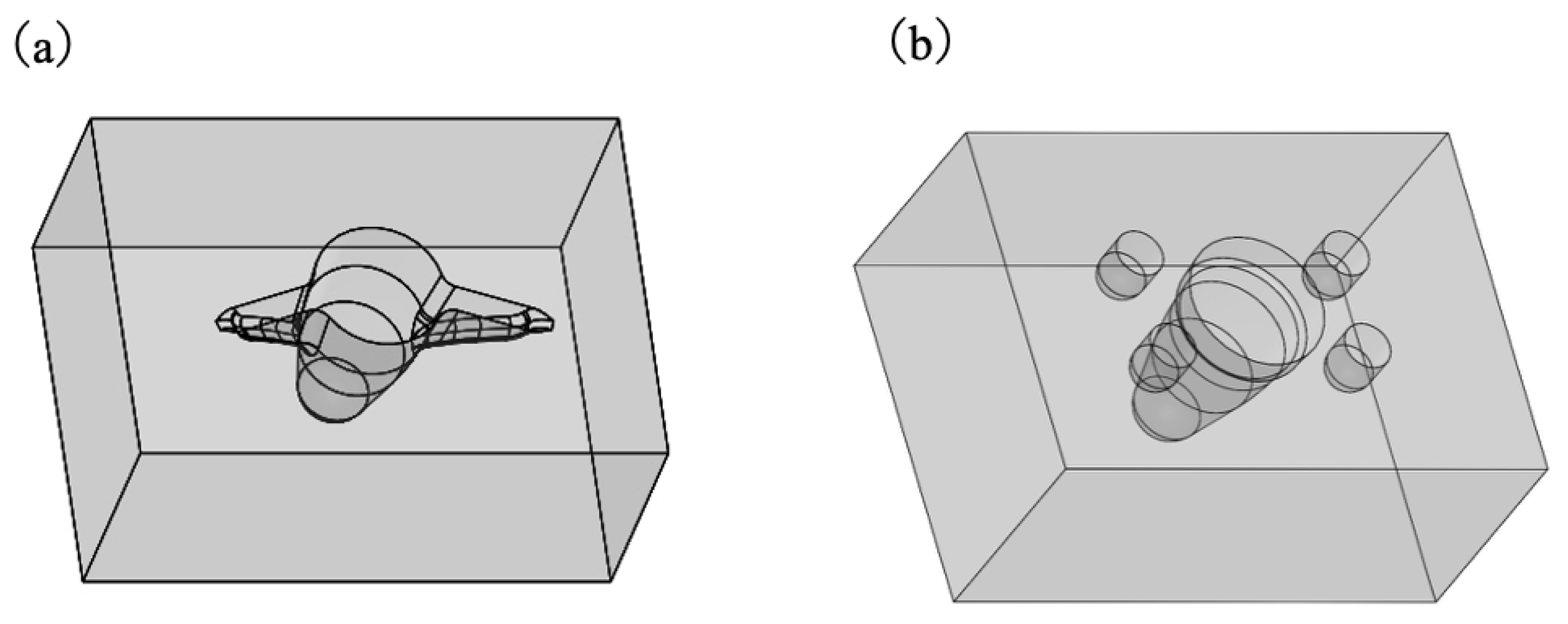
Figure 7.
Schematic of apparatus used for push-out test method as means of measuring fixation strength of tibial tray–bone complexes.
Figure 7.
Schematic of apparatus used for push-out test method as means of measuring fixation strength of tibial tray–bone complexes.
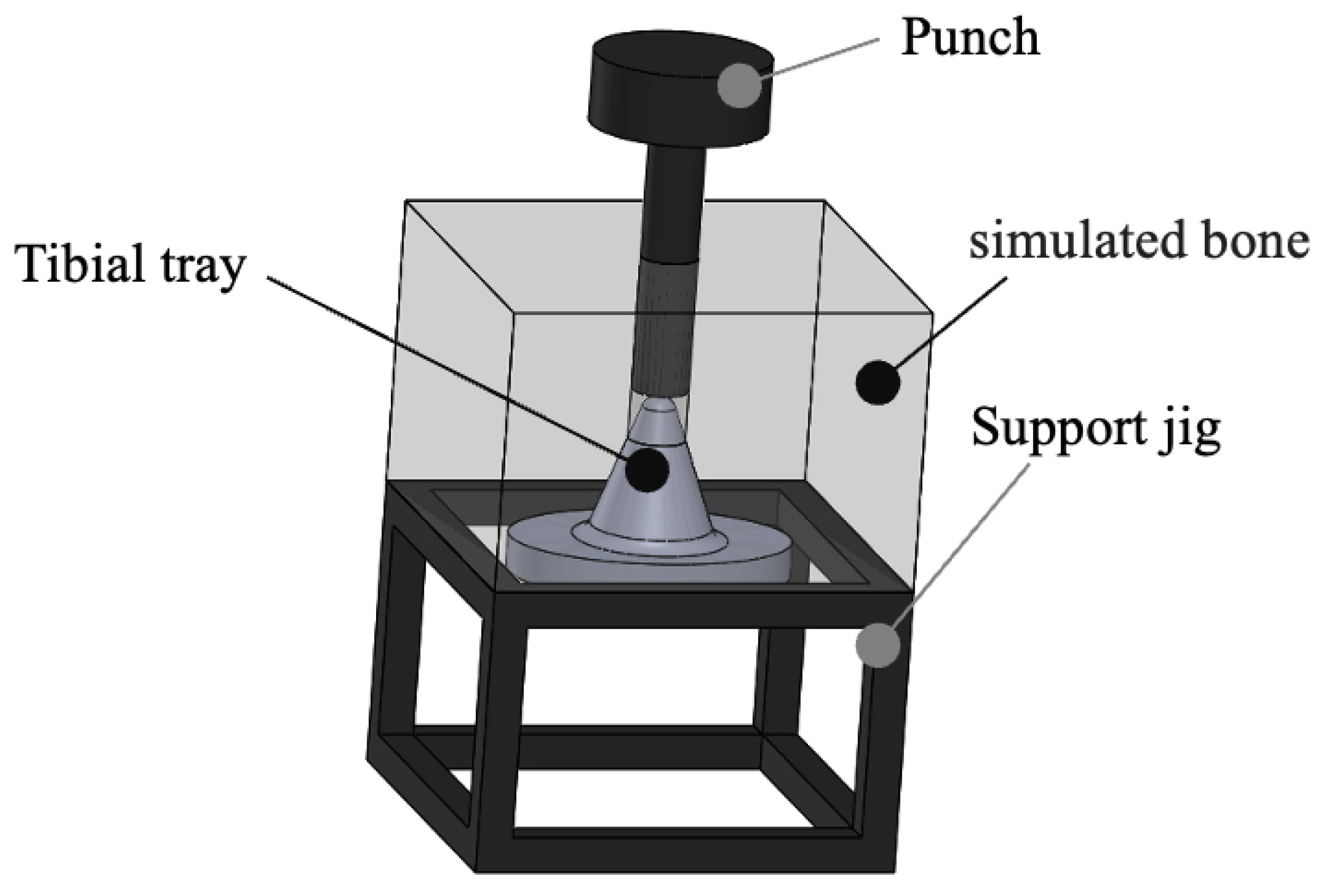
Figure 8.
SEM images of β-TCP particles synthesized by solid-state reaction (left) before spray drying, showing irregular morphology and sizes of 2–5 µm, and (right) after spray drying and sintering, showing spherical porous granules and sizes of 25–40 µm.
Figure 8.
SEM images of β-TCP particles synthesized by solid-state reaction (left) before spray drying, showing irregular morphology and sizes of 2–5 µm, and (right) after spray drying and sintering, showing spherical porous granules and sizes of 25–40 µm.
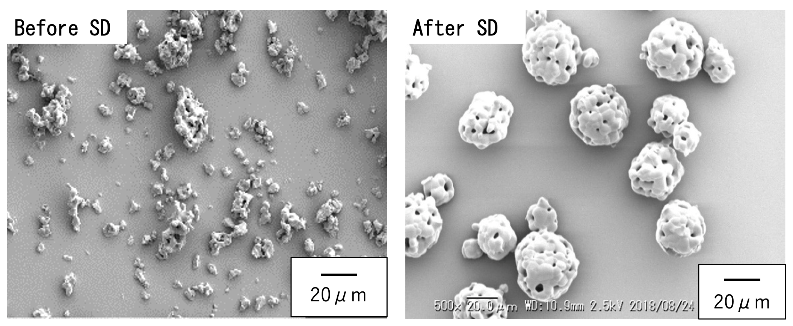
Figure 9.
XRD patterns for spherical, porous, sintered β-TCP, Mg9.0-β-TCP and NaMg-β- TCP/Si particles. All samples produced characteristic β-TCP peaks without secondary phases.
Figure 9.
XRD patterns for spherical, porous, sintered β-TCP, Mg9.0-β-TCP and NaMg-β- TCP/Si particles. All samples produced characteristic β-TCP peaks without secondary phases.
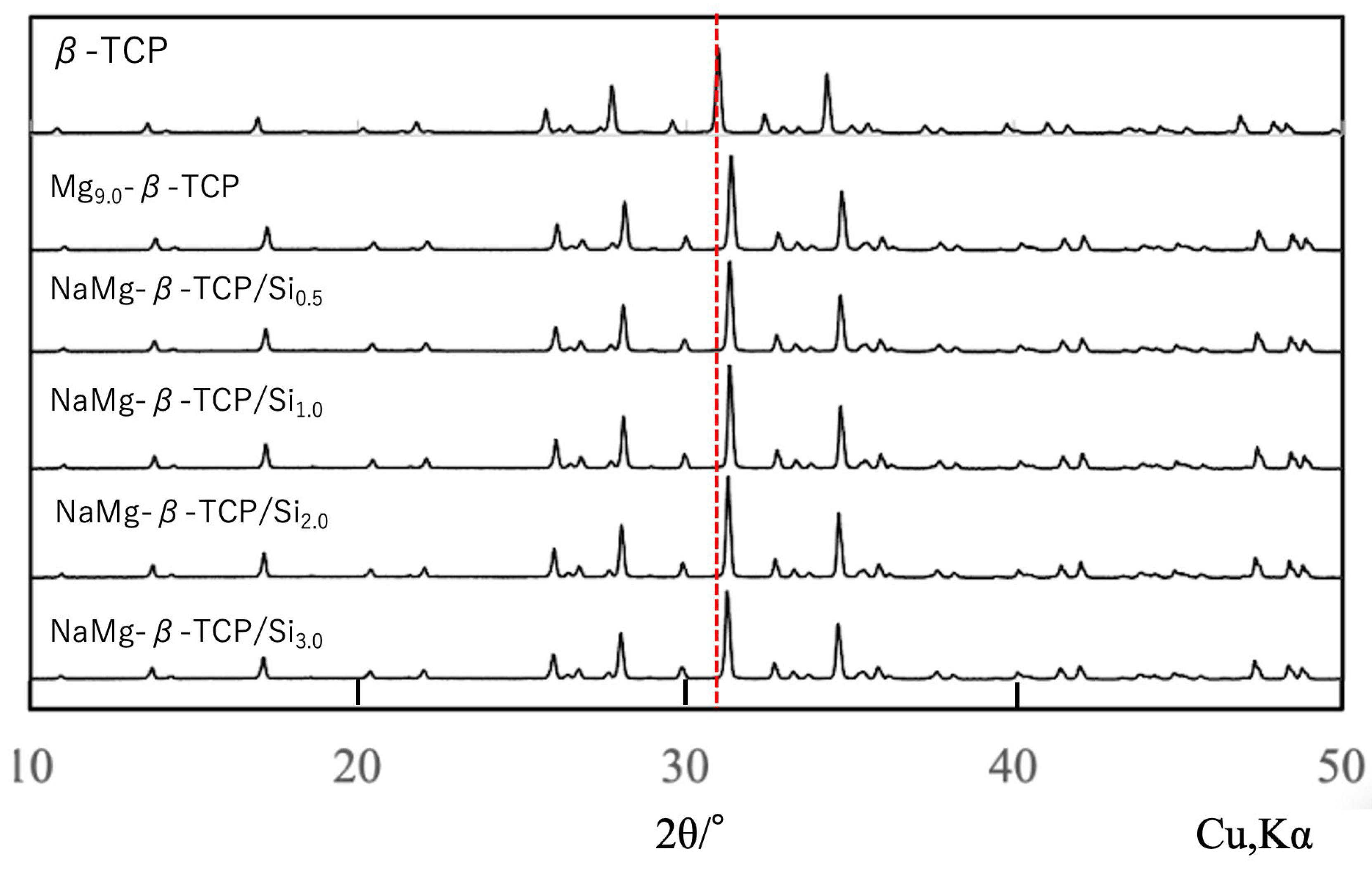
Figure 10.
Lattice constants (a, c) for β-TCP, Mg9.0-β-TCP and NaMg-β-TCP/Si as deter- mined by XRD. Mg substitution reduced both lattice parameters whereas Si and Na substitution slightly increased the a-axis parameter.
Figure 10.
Lattice constants (a, c) for β-TCP, Mg9.0-β-TCP and NaMg-β-TCP/Si as deter- mined by XRD. Mg substitution reduced both lattice parameters whereas Si and Na substitution slightly increased the a-axis parameter.
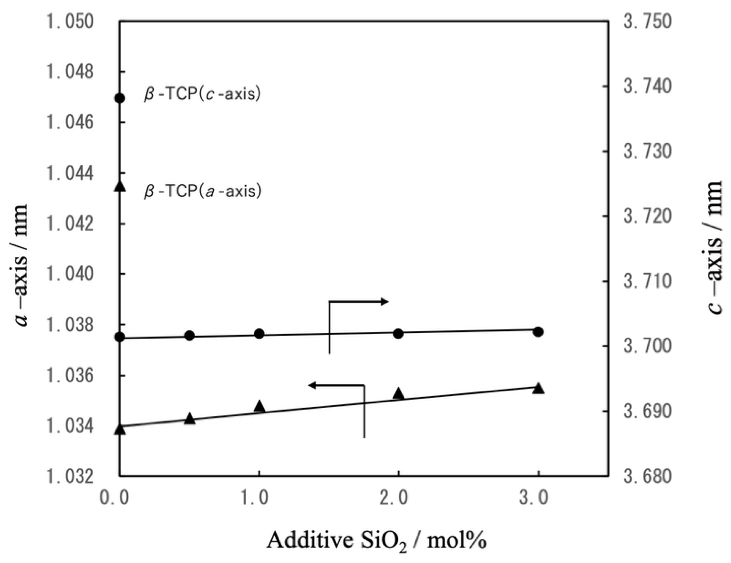
Figure 11.
FT-IR spectra of spherical, porous, sintered particles of (a) β-TCP, (b) Mg9.0-β- TCP, (c) NaMg-β-TCP/Si0.5, (d) NaMg-β-TCP/Si1.0, (e) NaMg-β-TCP/Si2.0 and (f) NaMg-β-TCP/Si3.0.
Figure 11.
FT-IR spectra of spherical, porous, sintered particles of (a) β-TCP, (b) Mg9.0-β- TCP, (c) NaMg-β-TCP/Si0.5, (d) NaMg-β-TCP/Si1.0, (e) NaMg-β-TCP/Si2.0 and (f) NaMg-β-TCP/Si3.0.
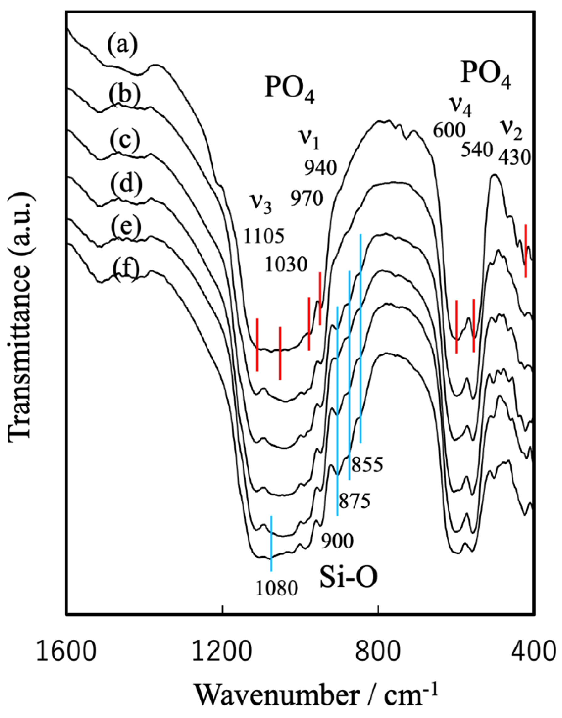
Figure 12.
Schematic representation of β-TCP crystal structure. (a) Atomic arrangement along the a-axis, highlighting the A- and B-columns and (b) crystal structure with half the length relative to the c-axis direction, showing Mg ions substituted at Ca(5) sites, Na ions at Ca(4) sites and Si ions at P(1) sites [38,39,41].
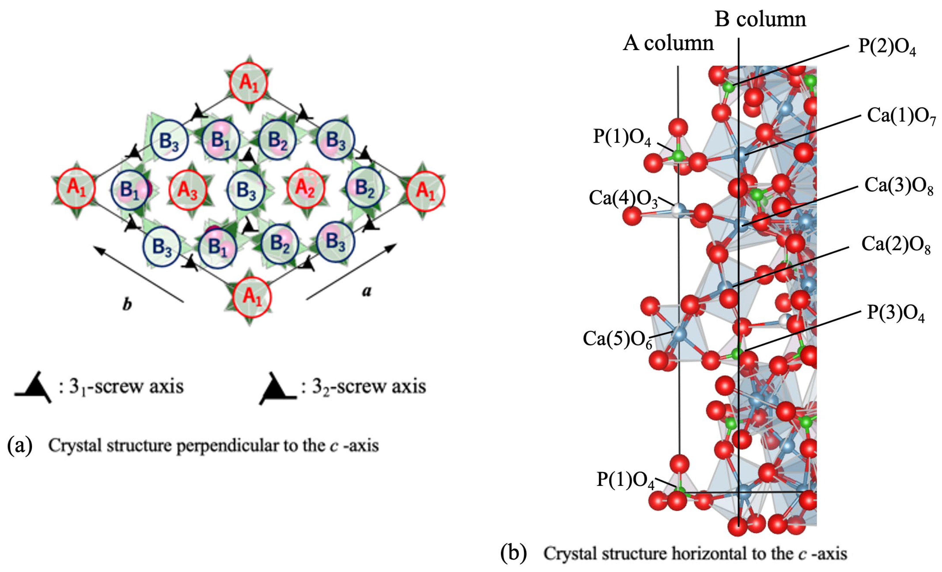
Figure 13.
Setting times and peak exothermic temperatures of BC specimens preparedfrom β-TCP, Mg9.0-β-TCP or NaMg-β-TCP/Si particles and a cyanoacrylate at L/P ratios of 0.7–0.9 mL/g.
Figure 13.
Setting times and peak exothermic temperatures of BC specimens preparedfrom β-TCP, Mg9.0-β-TCP or NaMg-β-TCP/Si particles and a cyanoacrylate at L/P ratios of 0.7–0.9 mL/g.
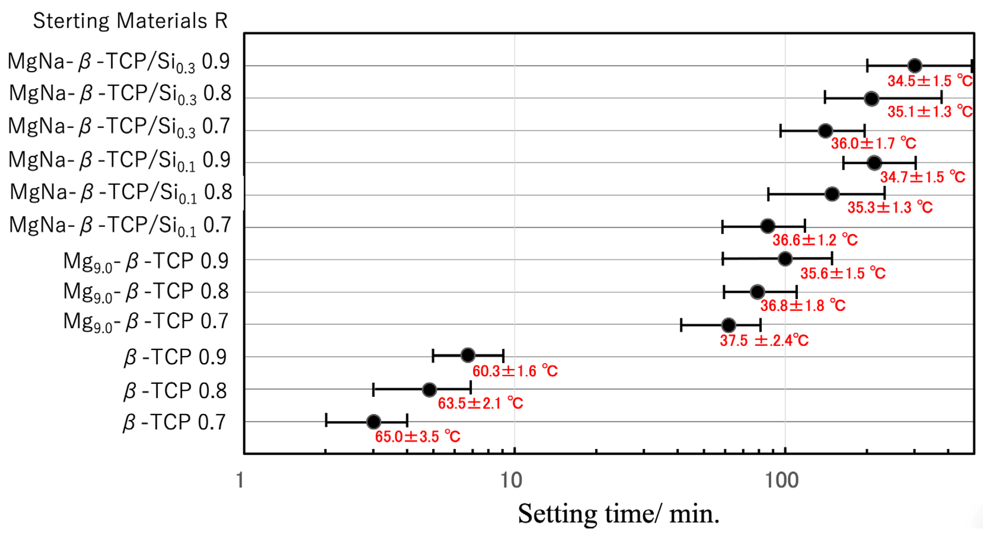
Figure 14.
Optimization of setting behavior based on combining β-TCP and NaMg-β- TCP/Si2.0 in various ratios.
Figure 14.
Optimization of setting behavior based on combining β-TCP and NaMg-β- TCP/Si2.0 in various ratios.
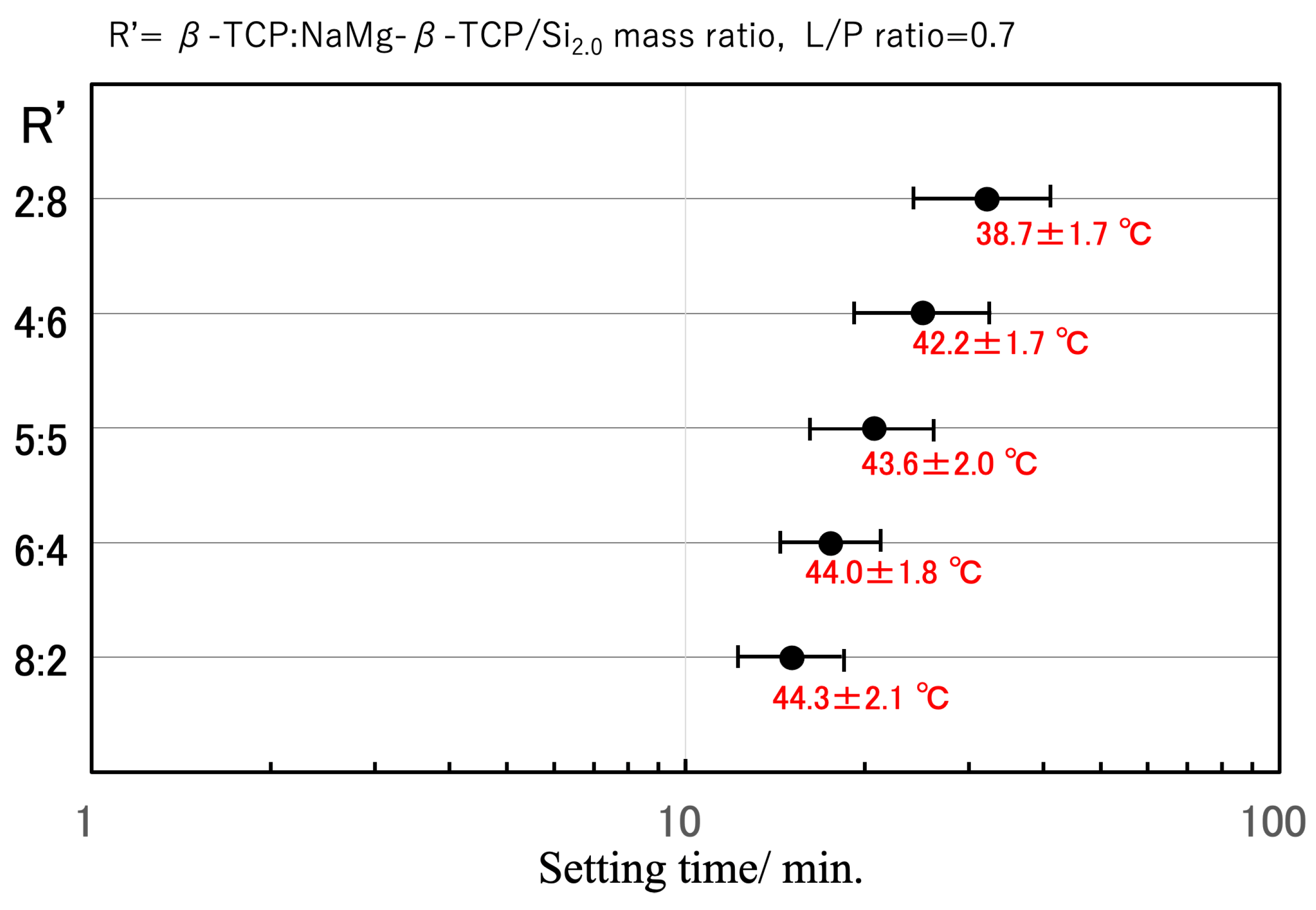
Figure 15.
Surface acidities of β-TCP, Mg9.0-β-TCP and NaMg-β-TCP/Si particles as mea- sured by pyridine adsorption, showing increases in the quantity of Brønsted acid sites with increasing Si substitution.
Figure 15.
Surface acidities of β-TCP, Mg9.0-β-TCP and NaMg-β-TCP/Si particles as mea- sured by pyridine adsorption, showing increases in the quantity of Brønsted acid sites with increasing Si substitution.
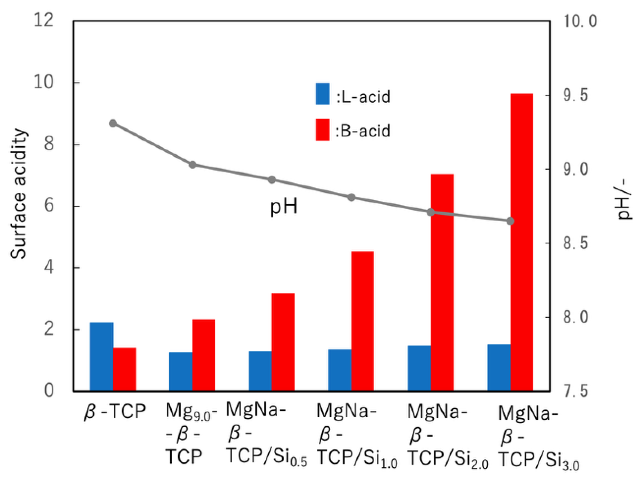
Figure 16.
Disintegration resistance of BC paste incorporating β-TCP:NaMg-β-TCP/Si0.5 particle mixture with ratio of 6:4 in saline over a 336 h trial. The specimen exhibited a minimal mass loss on the order of 0.3%.
Figure 16.
Disintegration resistance of BC paste incorporating β-TCP:NaMg-β-TCP/Si0.5 particle mixture with ratio of 6:4 in saline over a 336 h trial. The specimen exhibited a minimal mass loss on the order of 0.3%.
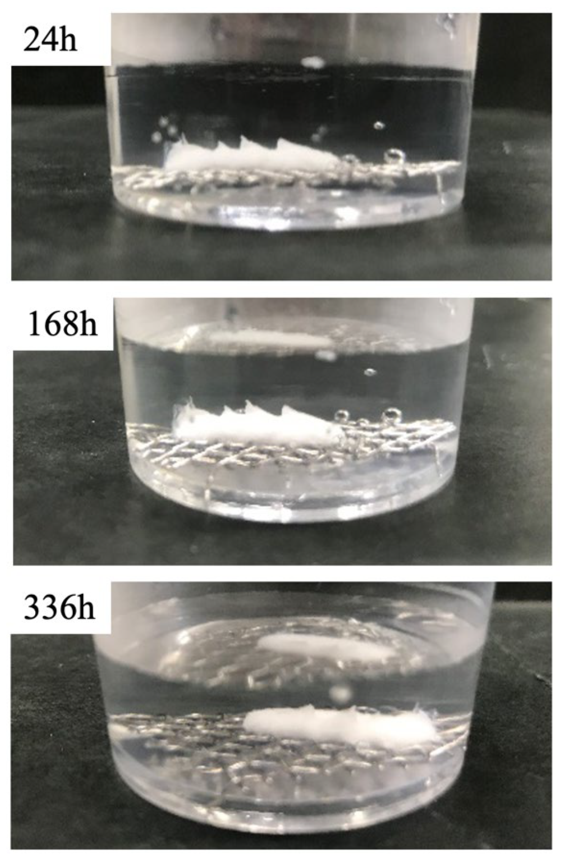
Figure 17.
Injectability of BC paste demonstrated by extrusion through syringe into saline solution while maintaining structural integrity and forming superficial reaction layer.
Figure 17.
Injectability of BC paste demonstrated by extrusion through syringe into saline solution while maintaining structural integrity and forming superficial reaction layer.
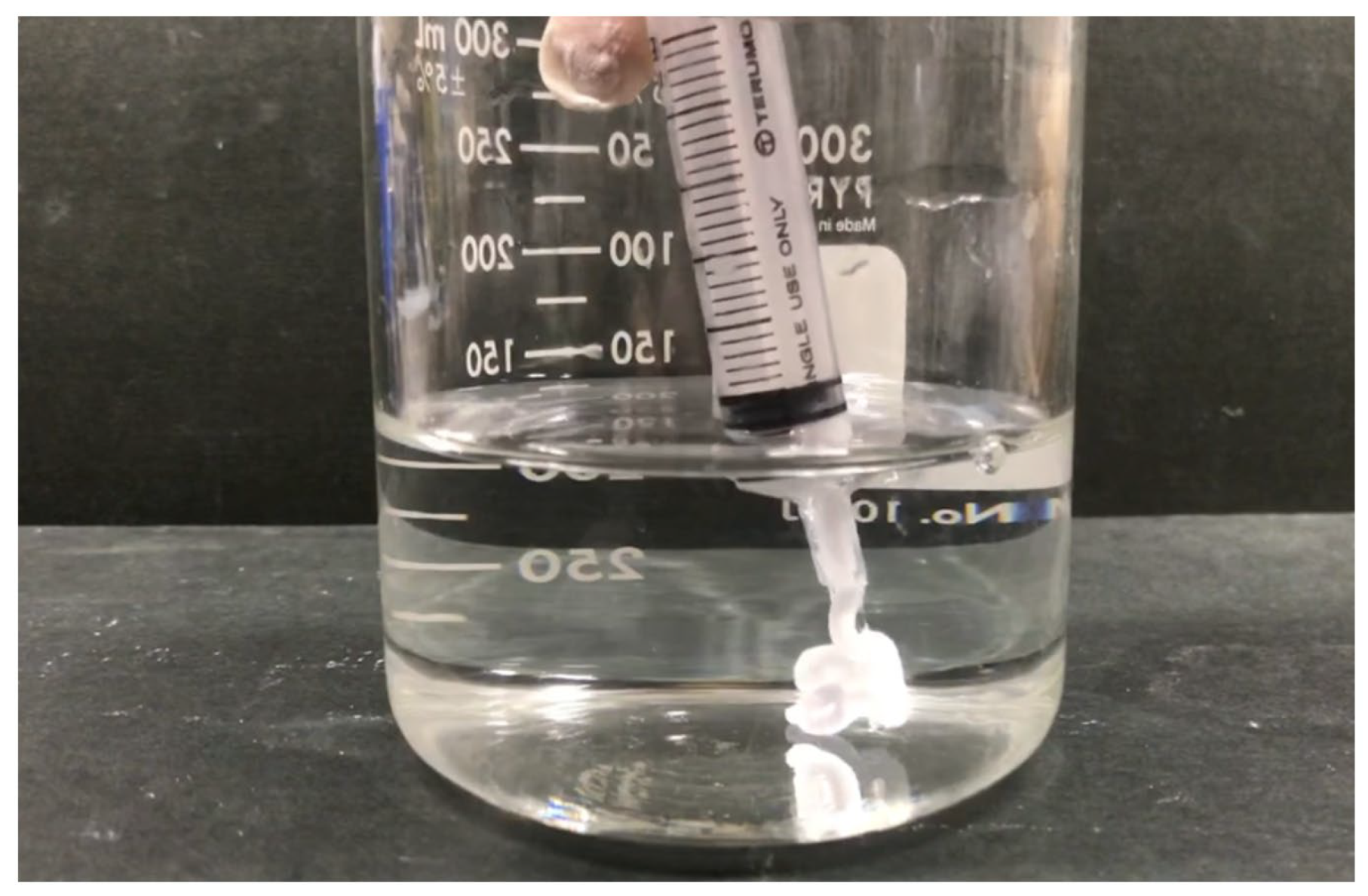
Figure 18.
FT-IR spectra of cured BC cross-sections at different curing times, showing progressive cyanoacrylate polymerization.
Figure 18.
FT-IR spectra of cured BC cross-sections at different curing times, showing progressive cyanoacrylate polymerization.
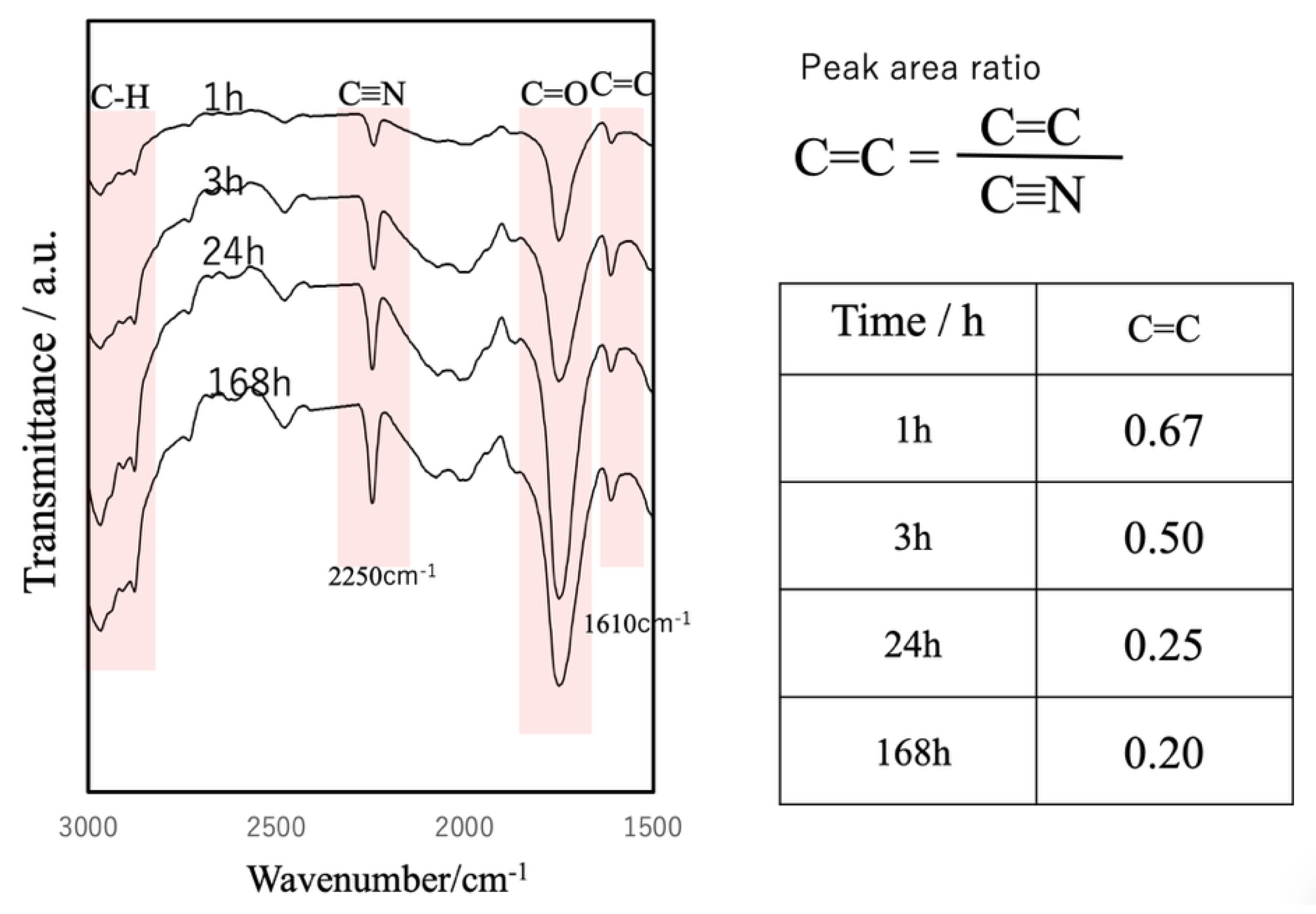
Figure 19.
Changes in compressive strength of cured BC in PBS (pH 7.4) as function of cur ing time, stabilizing at approximately 40 MPa after 144 h.
Figure 19.
Changes in compressive strength of cured BC in PBS (pH 7.4) as function of cur ing time, stabilizing at approximately 40 MPa after 144 h.
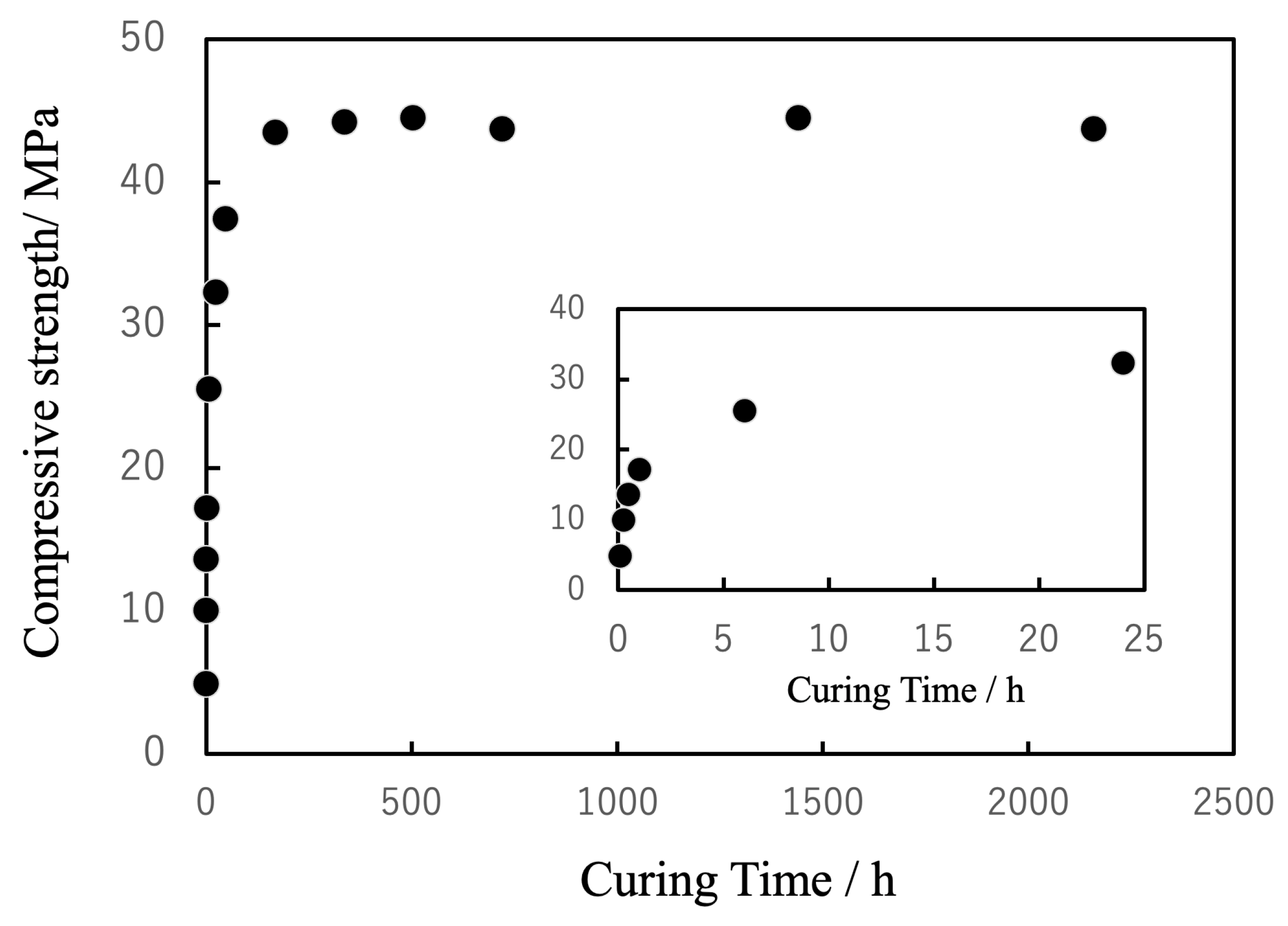
Figure 20.
Microstructure of cured BC. (a) SEM images showing the dispersion of the spherical, porous particles and (b) EPMA elemental maps of Ca confirming uniform particle distributions.
Figure 20.
Microstructure of cured BC. (a) SEM images showing the dispersion of the spherical, porous particles and (b) EPMA elemental maps of Ca confirming uniform particle distributions.
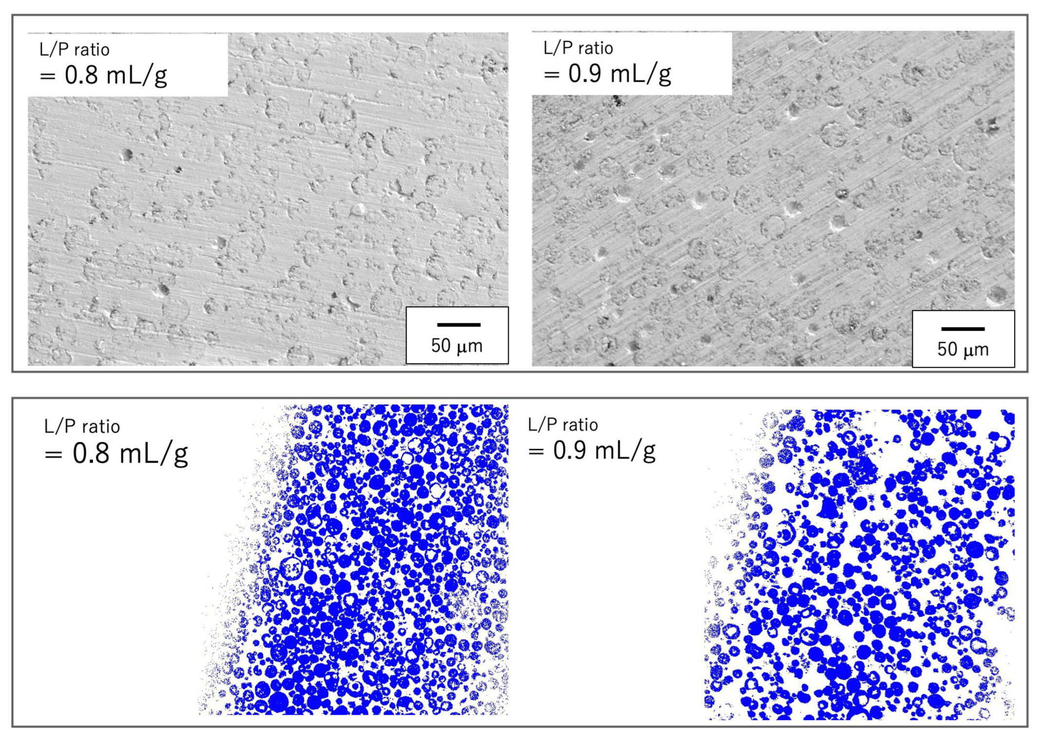
Figure 21.
Tensile stress as function of crosshead displacement for five BC specimens.
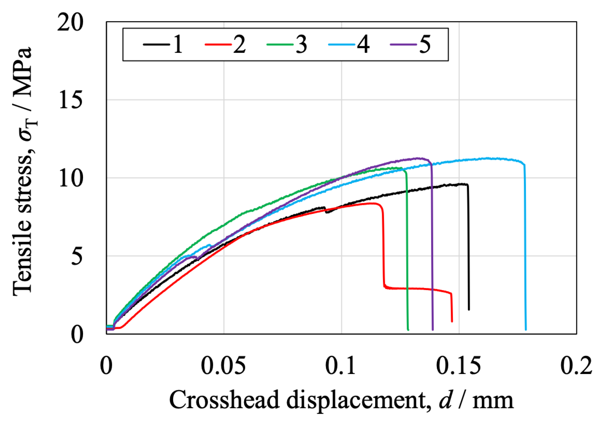
Figure 22.
Compressive stress as function of crosshead displacement for (a) five BC specimens and (b) five CPC specimens.
Figure 22.
Compressive stress as function of crosshead displacement for (a) five BC specimens and (b) five CPC specimens.
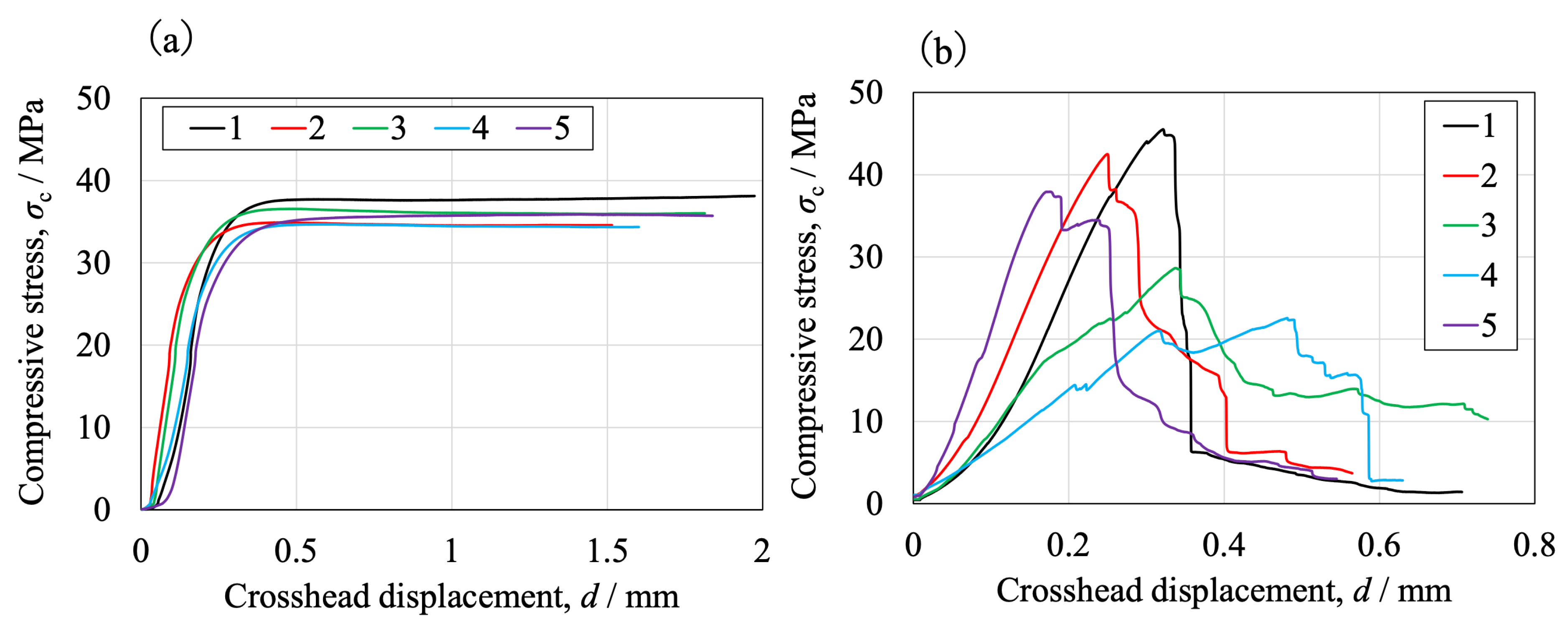
Figure 23.
Appearance of BC specimens before and after compression, indicating ductile fracture.
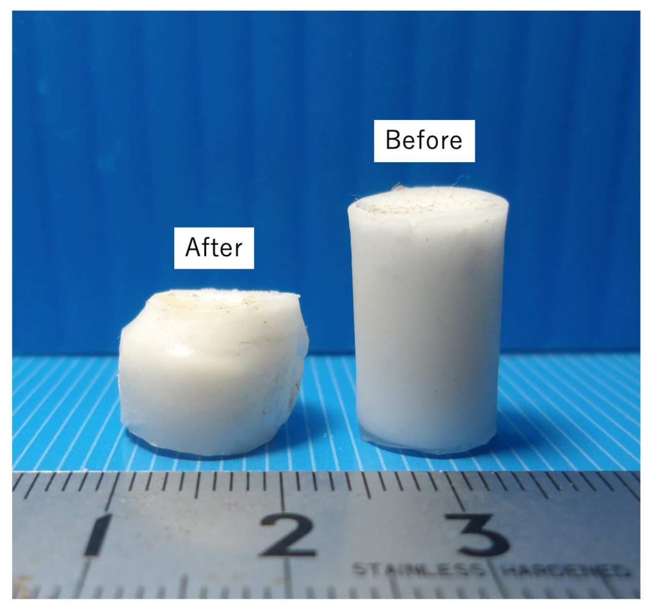
Figure 24.
Bending stress as a function of crosshead displacement for (a) five BC speci mens and (b) five CPC specimens.
Figure 24.
Bending stress as a function of crosshead displacement for (a) five BC speci mens and (b) five CPC specimens.
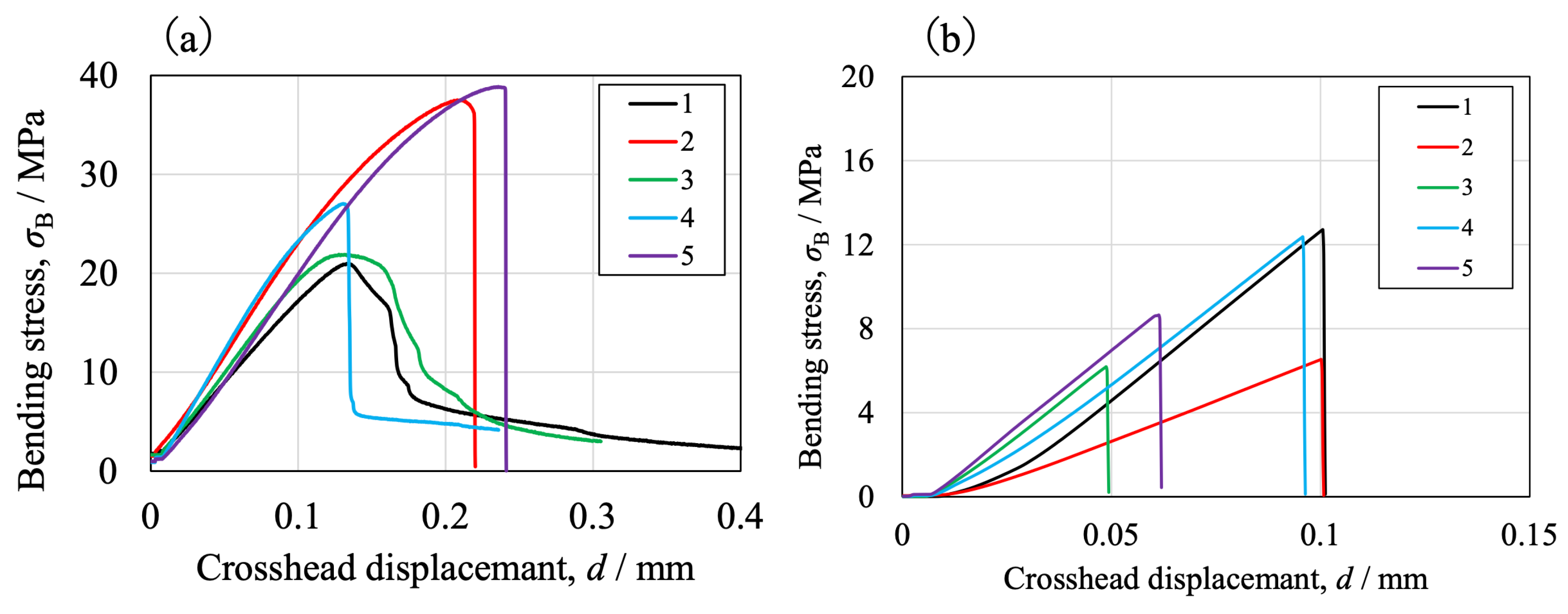
Figure 25.
Surface shear stress as function of angle of rotation for five BC specimens.
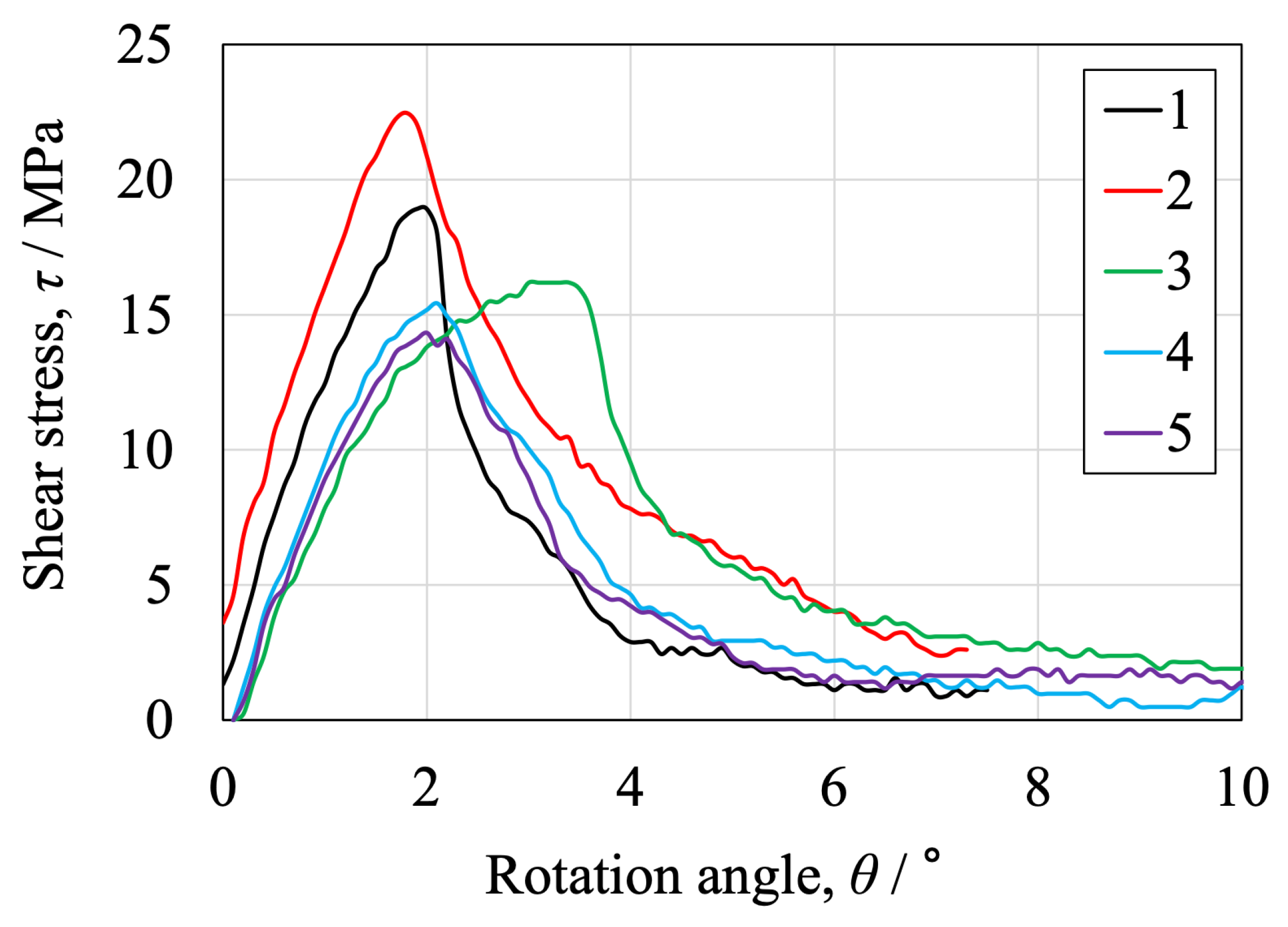
Figure 26.
Fatigue S–N curves for BC specimens under cyclic loading (±3 MPa, 5 × 10⁶ cycles).
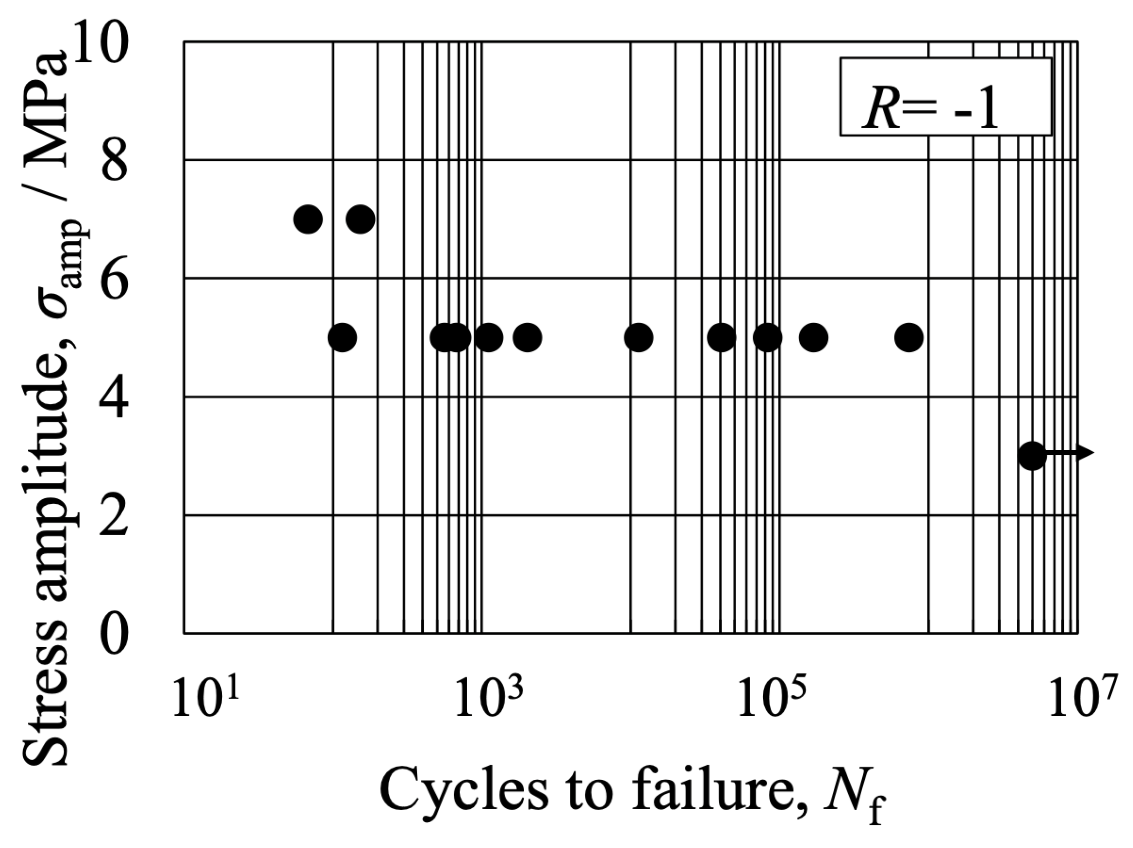
Figure 27.
Load-time relationship obtained from Charpy impact tests for (a) five BC speci mens and (b) five CPC specimens.
Figure 27.
Load-time relationship obtained from Charpy impact tests for (a) five BC speci mens and (b) five CPC specimens.
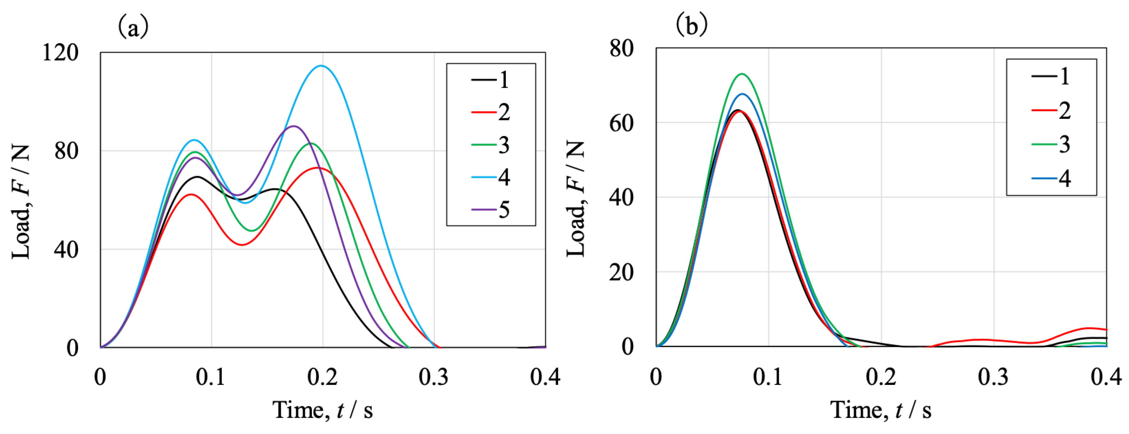
Figure 28.
Images showing (a) BC specimens fractured into two pieces and (b) CPC speci- mens fractured into multiple fragments following impact.
Figure 28.
Images showing (a) BC specimens fractured into two pieces and (b) CPC speci- mens fractured into multiple fragments following impact.
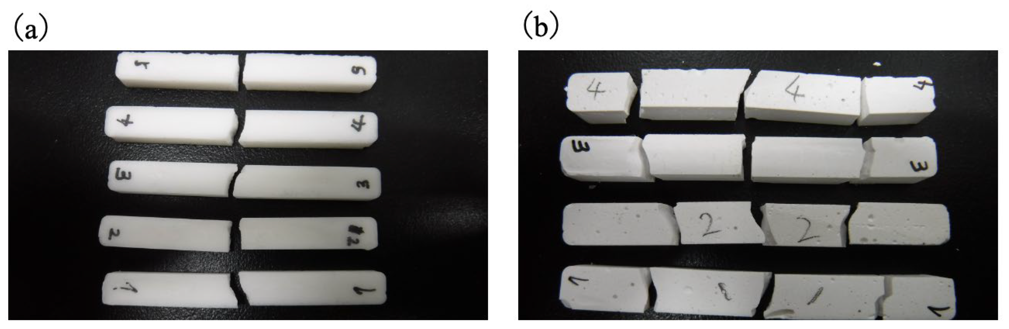
Figure 29.
Representative fracture modes observed in three specimens selected from total of nine tests conducted for each density group. The fracture modes were determined through visual inspection. Images are shown for (a) H specimen with density of 20 PCF (0.32 g / cm3), (b) M specimen with density of 12.5 PCF (0.20 g / cm3) and (c) L specimen with density of 7.5 PCF (0.12 g/cm3).
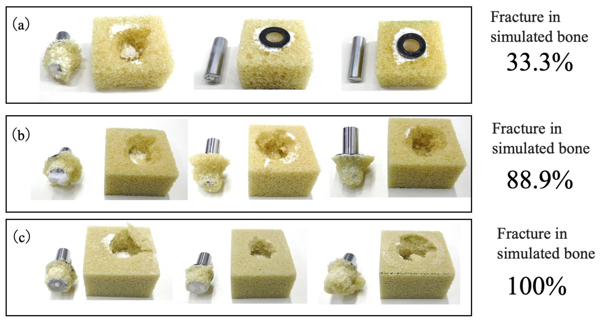
Figure 30.
X-ray CT images showing BC penetration into porous simulated bones having (a) L, (b) M and (c) H density levels.
Figure 30.
X-ray CT images showing BC penetration into porous simulated bones having (a) L, (b) M and (c) H density levels.
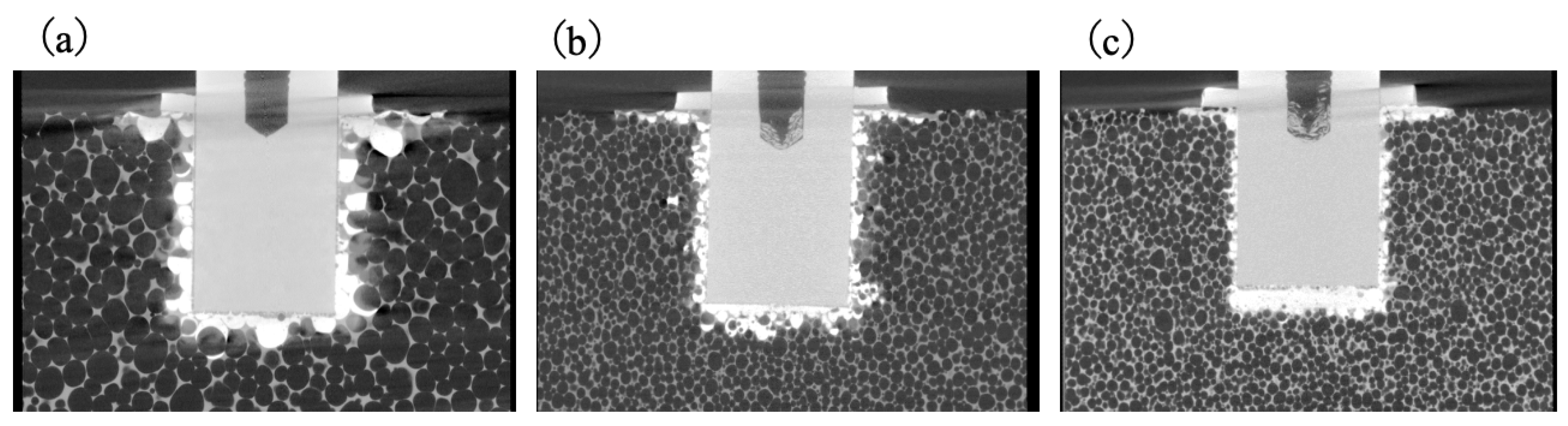
Figure 31.
Photographic images of simulated bone specimens having (a) L, (b) M and (c) H densities after fracture during tensile tests.
Figure 31.
Photographic images of simulated bone specimens having (a) L, (b) M and (c) H densities after fracture during tensile tests.
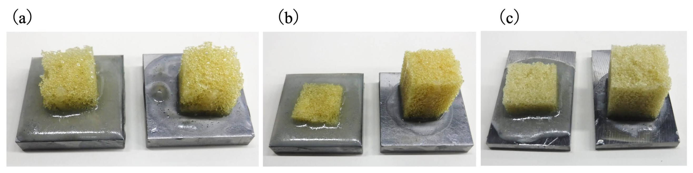
Figure 32.
Tensile strength results of simulated bone blocks with different densities (L, M, H).
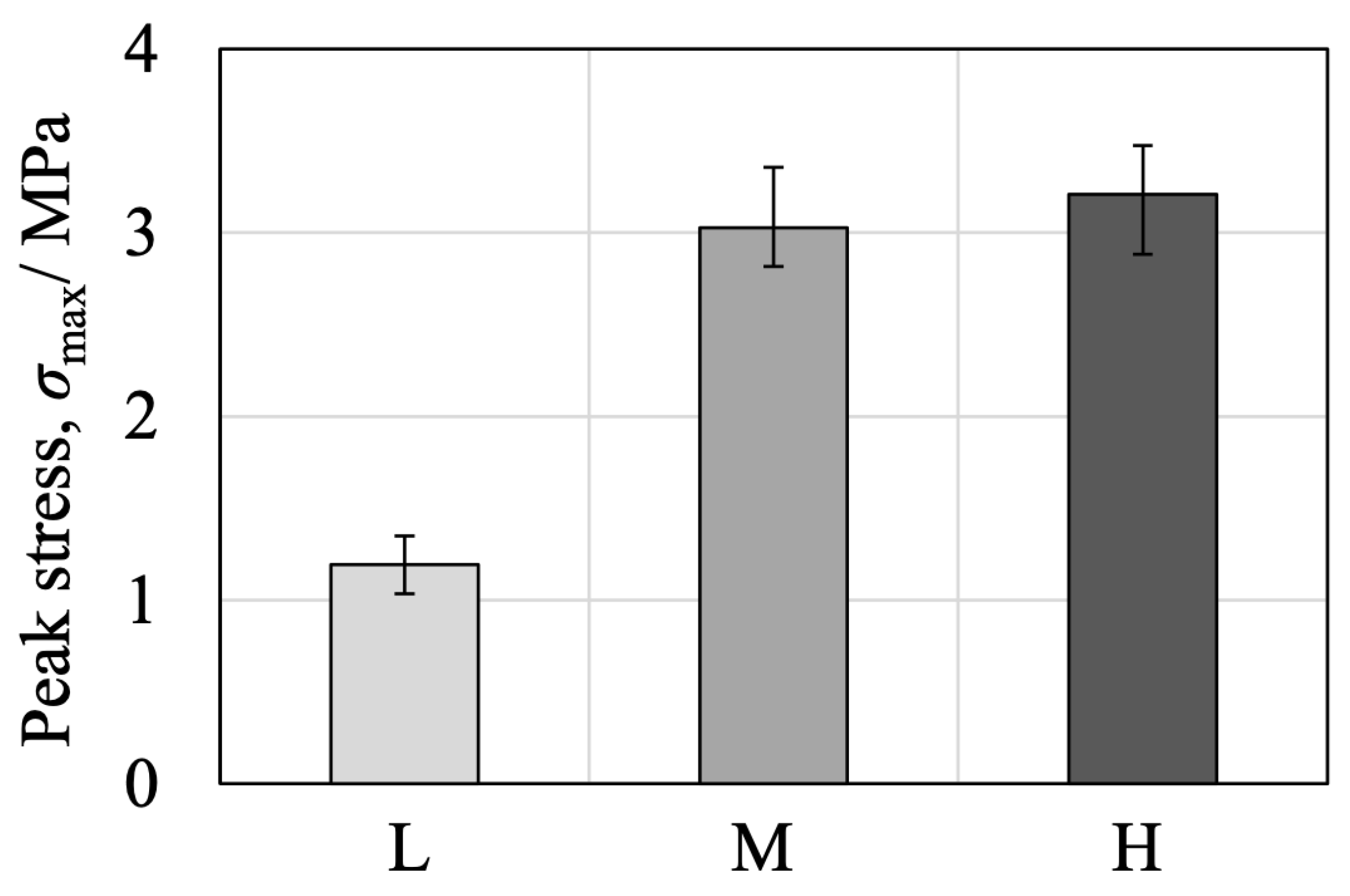
Figure 33.
Photographic images of cemented tibial trays fixed with present BC in simulated bone. Images show specimens (a) prior to and (b–f) after push-out tests (samples 1–5).
Figure 33.
Photographic images of cemented tibial trays fixed with present BC in simulated bone. Images show specimens (a) prior to and (b–f) after push-out tests (samples 1–5).
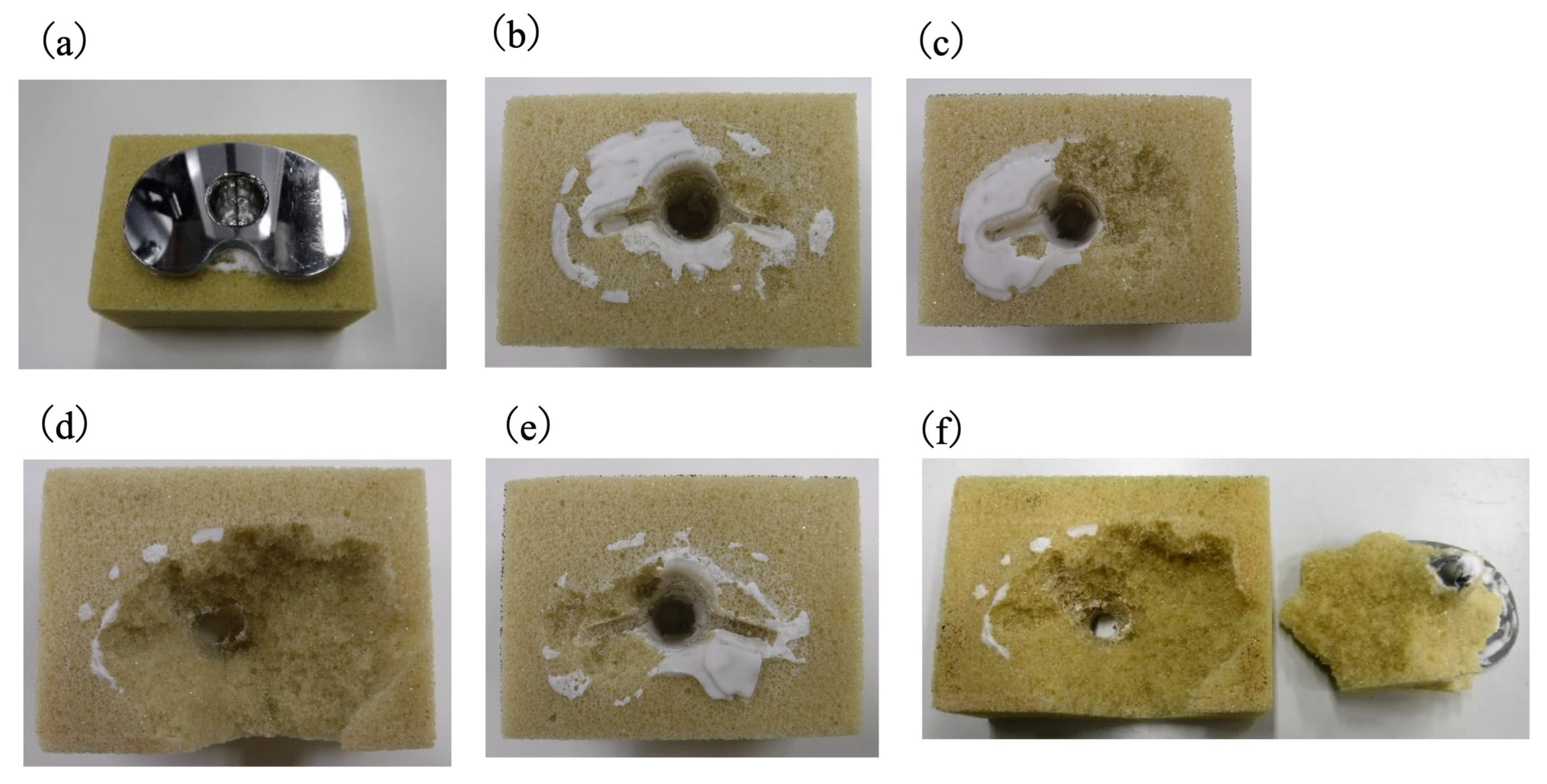
Figure 34.
Tensile strength data for simulated bone blocks having different densities (L, M or H) fixed with (a) present BC and (b) PMMA-based BC.
Figure 34.
Tensile strength data for simulated bone blocks having different densities (L, M or H) fixed with (a) present BC and (b) PMMA-based BC.
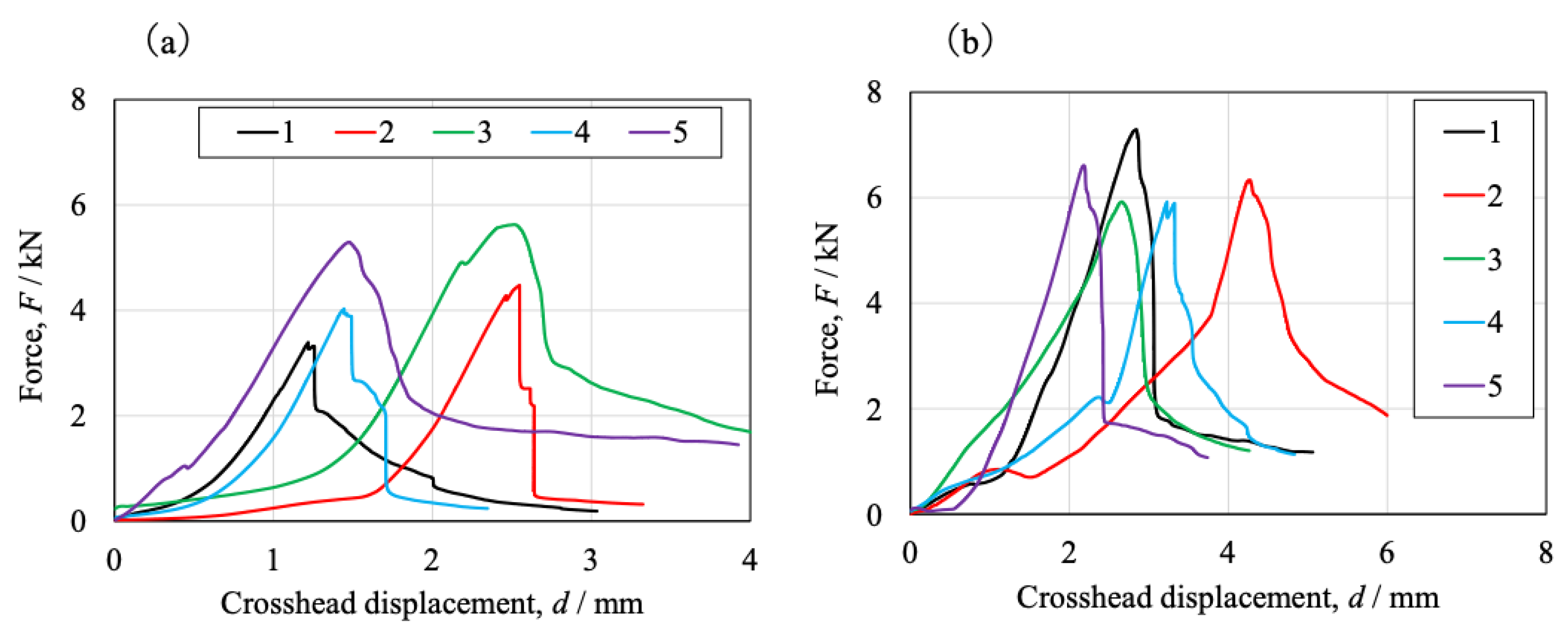
Figure 35.
Photographic images of cementless type tibial trays fixed to simulated bone using the present BC. Images showing (a) specimen before the push-out test and (b) to (f) five samples after push-out test.
Figure 35.
Photographic images of cementless type tibial trays fixed to simulated bone using the present BC. Images showing (a) specimen before the push-out test and (b) to (f) five samples after push-out test.
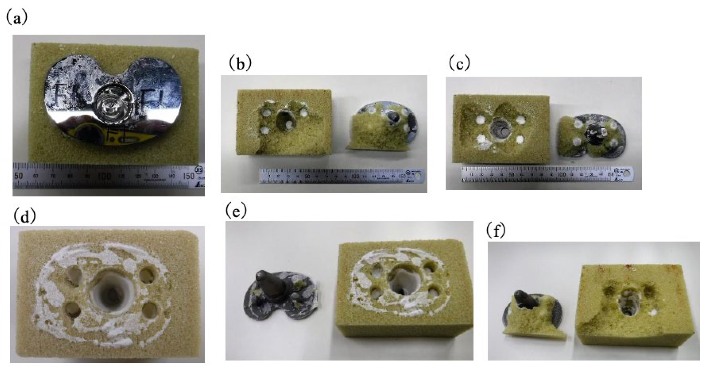
Figure 36.
Load–displacement relationships from push-out tests of cemented tibial traysfixed with (a) present BC and (b) PMMA-based BC.
Figure 36.
Load–displacement relationships from push-out tests of cemented tibial traysfixed with (a) present BC and (b) PMMA-based BC.
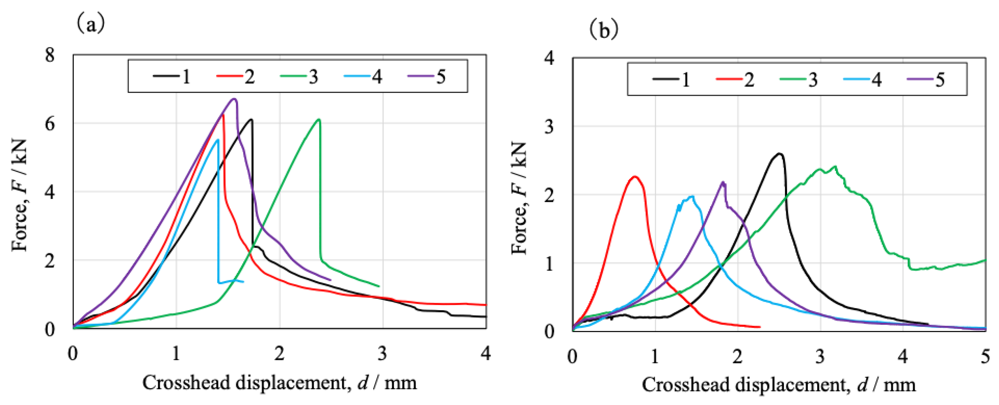

Table 1.
Chemical compositions of raw powder mixtures.
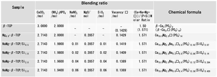
Table 2.
Summary of mechanical property values obtained from tensile, compressive, bending, torsional, fatigue and impact testing of BC specimens and comparison data for commercial bone fillers.
Table 2.
Summary of mechanical property values obtained from tensile, compressive, bending, torsional, fatigue and impact testing of BC specimens and comparison data for commercial bone fillers.
| Test method | Mechanical properties | Results (Mean ± SD) | |
| BC | Calcium phosphate based BC |
||
| Tensile | Peak tensile stress (MPa) | 10.2 ± 1.2 | ― |
| Elastic modulus (MPa) | 4 787 ± 590 | ― | |
| Compression | Peak compressive stress (MPa) | 36.0 ± 1.4 | 35.4 ± 9.6 |
| Elastic modulus (MPa) | 3 448 ± 390 | 4 590 ± 459 | |
| Bending | Peak bending stress (MPa) | 29.3 ± 8.5 | 9.29 ± 3.1 |
| Elastic modulus (MPa) | 2 169 ± 287 | 1 353 ± 413 | |
| Torsion | Peak shear stress (MPa) | 17.5 ± 3.3 | ― |
| Fatigue | fatigue life at 5 million cycles (MPa) |
3.00 | ― |
Disclaimer/Publisher’s Note: The statements, opinions and data contained in all publications are solely those of the individual author(s) and contributor(s) and not of MDPI and/or the editor(s). MDPI and/or the editor(s) disclaim responsibility for any injury to people or property resulting from any ideas, methods, instructions or products referred to in the content. |
© 2025 by the authors. Licensee MDPI, Basel, Switzerland. This article is an open access article distributed under the terms and conditions of the Creative Commons Attribution (CC BY) license (http://creativecommons.org/licenses/by/4.0/).
Copyright: This open access article is published under a Creative Commons CC BY 4.0 license, which permit the free download, distribution, and reuse, provided that the author and preprint are cited in any reuse.


