Preprint
Article

This version is not peer-reviewed.

Finite Element Analysis of Electrostatic Fields in Gas Ionization Chambers for Laser-Driven Proton Therapy

Submitted:

26 October 2025

Posted:

28 October 2025

You are already at the latest version

Abstract

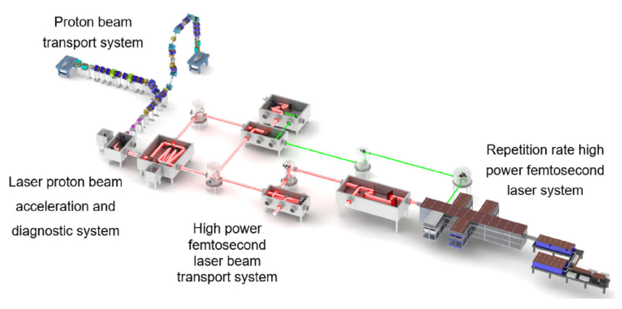
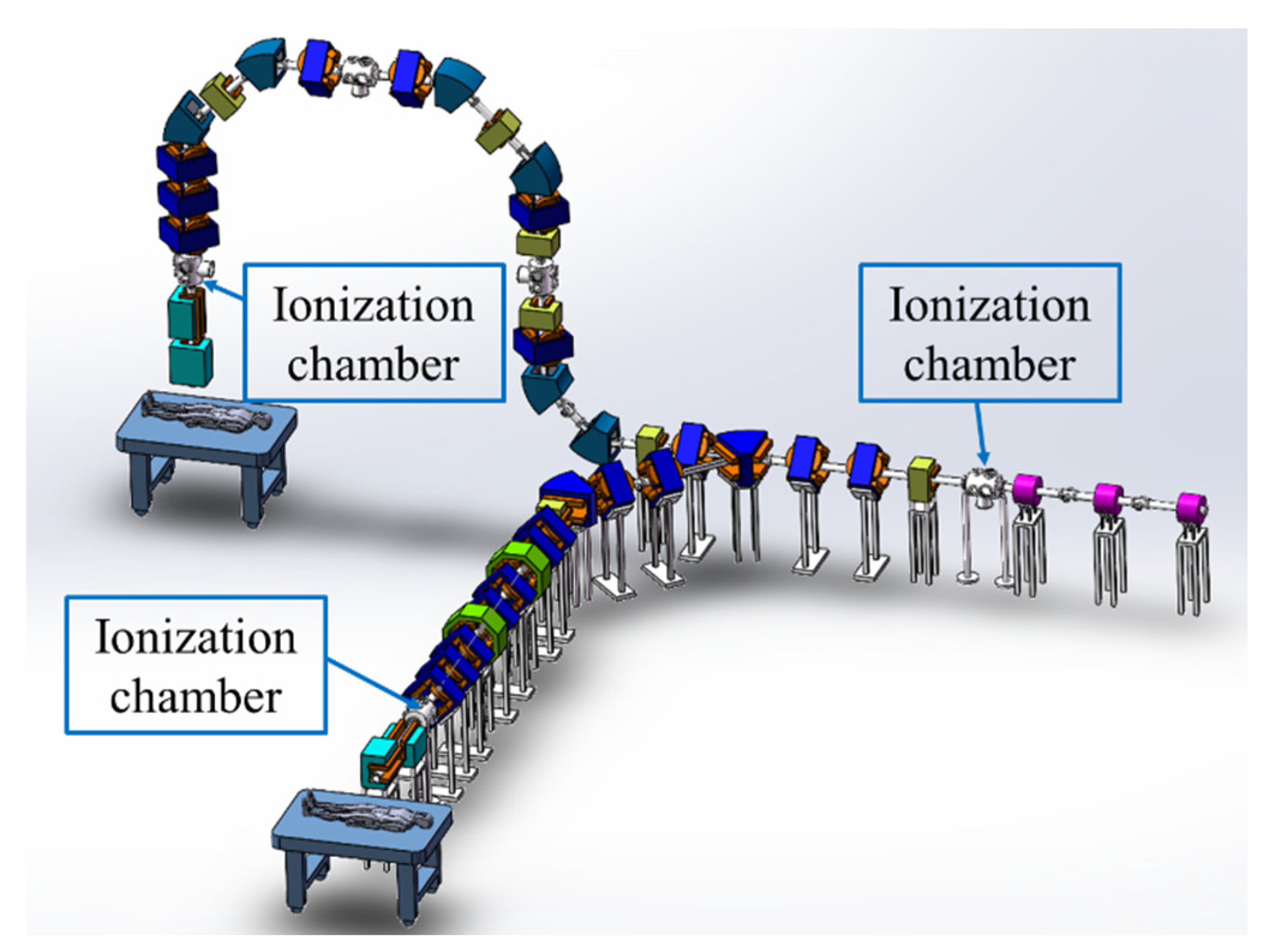
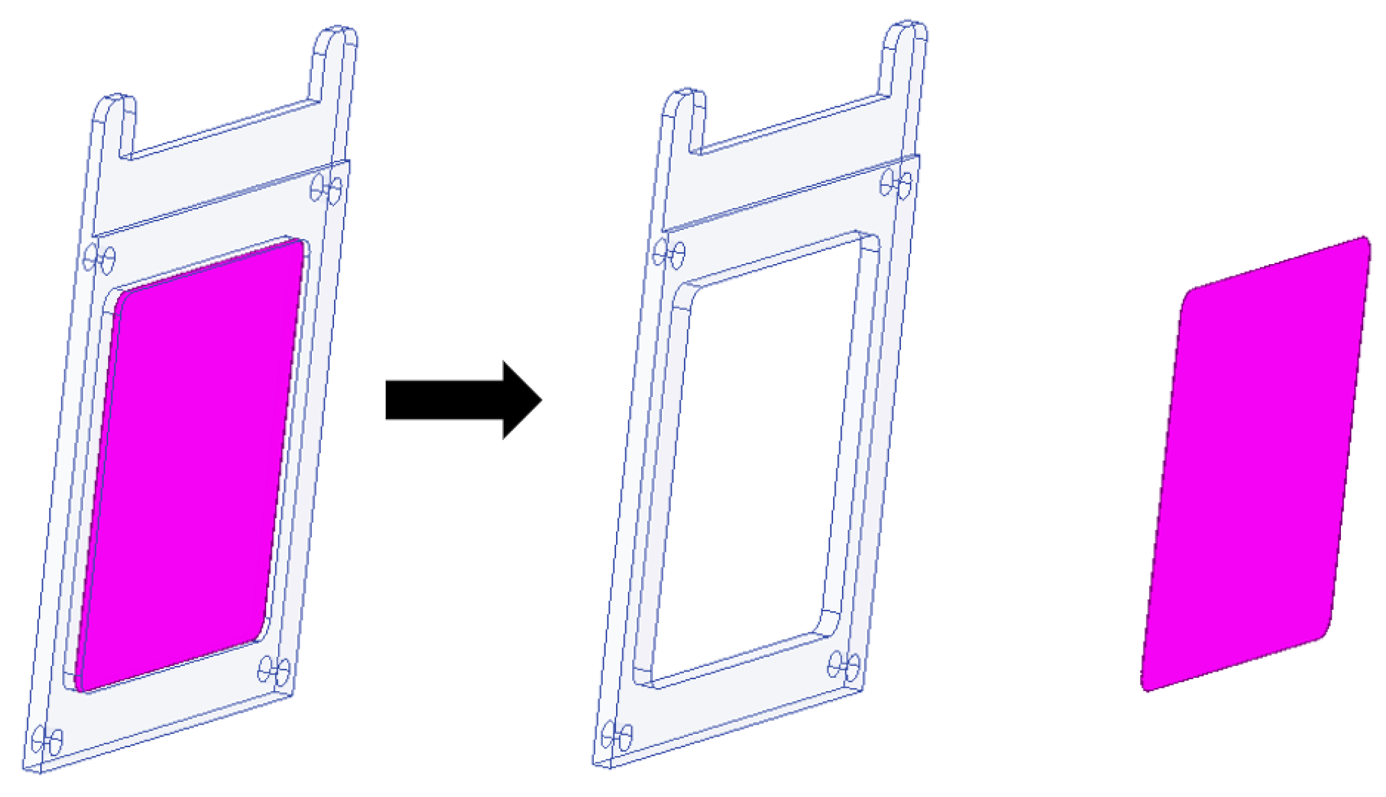
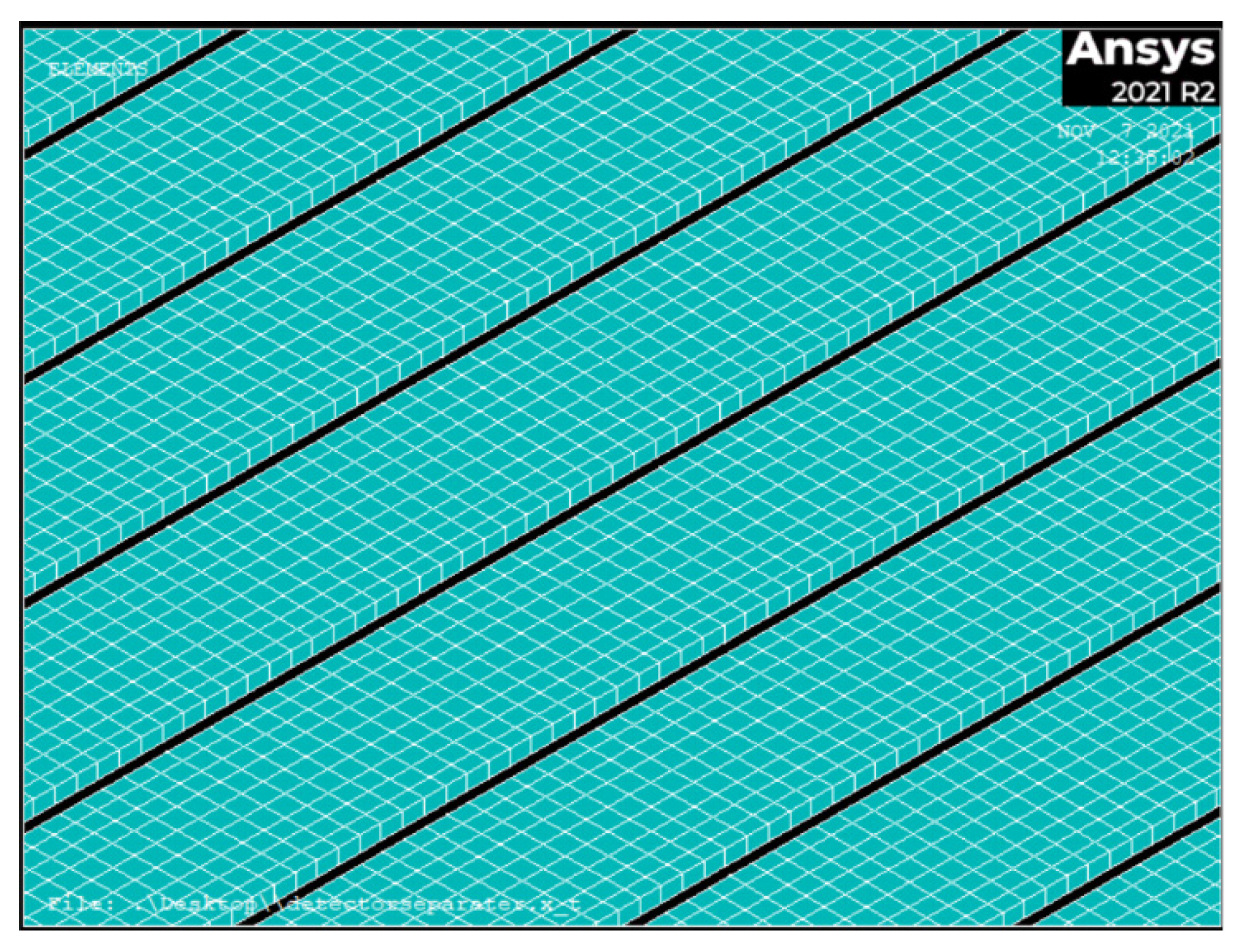
This paper presents a finite element analysis of the electrostatic field in gas ionization chambers used for beam diagnostics in laser-accelerated proton therapy systems. With the advent of laser-driven proton accelerators, such as the CLAPA-II project, there is a growing need for precise beam monitoring systems capable of handling high peak currents and large energy dispersion. Gas ionization chambers are widely employed for this purpose due to their reliability and accuracy. Using ANSYS software, this study establishes a detailed electrostatic finite element model of a multi-electrode ionization chamber. Key steps include model simplification, gas region definition, regional meshing, and solver selection. The analysis demonstrates the convergence of the electrostatic field solution and validates the model’s accuracy. The proposed modeling approach not only enhances computational efficiency but also facilitates interoperability with other simulation platforms such as Garfield++. This work provides a reliable foundation for optimizing ionization chamber design and improving beam diagnostic precision in advanced proton therapy applications.

Keywords: 
;  ;  ;  ;  ;  ;  

1. Introduction

Cancer remains the second leading cause of death globally, accounting for nearly one-sixth of all fatalities worldwide [1]. Radiotherapy is one of the primary treatment modalities, significantly improving patient survival rates and quality of life. Compared to conventional photon or electron radiotherapy, proton beam therapy offers superior dose localization due to the Bragg peak effect, which deposits maximum energy within the tumor while sparing surrounding healthy tissues [2].
Traditional radiofrequency (RF) medical accelerators are large, costly, and expensive to maintain. In contrast, laser-driven plasma accelerators can achieve significantly higher acceleration gradients, potentially reducing the size and cost of proton therapy systems [3,4]. Recent advances have enabled laser-accelerated proton beams with energies up to 70 MeV [5], opening new possibilities for medical applications [6,7]. Proton beams above 100 MeV are sufficient to treat shallow-seated tumors and most childhood cancers [8], making laser-based proton therapy a promising research direction [9,10]. Several international facilities are exploring laser-driven proton therapy, including the Center for Advanced Laser Applications (CALA) in Germany [11,12], ELIMED in the EU [13,14], LhARA in the UK [15], and CLAPA-II in China [16]. The CLAPA-II project, developed by Peking University, aims to deliver 100–200 MeV proton beams for clinical irradiation [17,18].
Figure 1. Layout of CLAPA-Ⅱ.
Preprints 182366 g001
Accurate beam diagnostics are essential for the safe and effective application of laser-accelerated protons. Gas ionization chambers are widely used for beam monitoring in conventional proton therapy due to their reliability and accuracy. However, laser-accelerated beams exhibit unique characteristics, such as high peak current and large energy dispersion, which challenge traditional ionization chamber designs [19,20]. This study addresses these challenges through an optimized finite element modeling approach using ANSYS, ensuring robust electrostatic field analysis and seamless integration with simulation tools like Garfield++.
Figure 2. Position distribution of ionization chamber on proton beam line.
Preprints 182366 g002

2. Principle and Technical Background

2.1. Gas Ionization Chamber Working Principle

The working principle of a gas ionization chamber (as shown in Figure 3) involves charged particles passing through the sensitive volume of the gas parallel-plate ionization chamber. These charged particles interact with the gas, exciting gas molecules and ionizing them to produce an ion pair (a positive ion and an electron) along their trajectory. The generated ion pairs possess initial kinetic energy and continuously collide with gas molecules in the chamber. Three physical processes can occur for these ion pairs: (a) Diffusion: Positive ions and electrons drift from regions of high density to regions of low density. (b) Electron Capture: Electrons can be captured by neutral gas molecules in the chamber, forming negative ions. (c) Recombination: Positive ions and electrons can recombine to form neutral molecules. Therefore, a voltage must be applied across the two electrodes of the gas ionization chamber to establish an electric field between them. This field causes the positive ions and electrons to overcome the process above and drift towards their respective electrodes for collection. Multiple electrode plates are stacked. The electronics system connected to the dose ionization chamber region reads out the charge information. The position ionization chamber region determines the beam position based on signals from both the X and Y directions. The beam distribution information is obtained from the signals collected at the signal anode (collecting electrode) of the detector.

2.2. Introduction to the ANSYS Platform and the Research Significance

ANSYS is a powerful engineering simulation software that can simulate a wide range of complex structures and systems.
The application of ANSYS electrostatic finite element analysis to gas ionization chambers holds the following significance: (1) Design Optimization: By analyzing the electrostatic field distribution within the gas ionization chamber, the shape, size, and position of the electrodes can be determined, thereby optimizing the design to improve plasma generation efficiency and stability.(2)Performance Prediction: Through simulation and analysis, the operational performance of the gas ionization chamber, including ionization efficiency, discharge power, plasma density, and temperature, can be predicted, providing references for subsequent experiments and applications.(3)Cost Reduction: Potential issues can be identified and resolved during the design phase through simulation and analysis, thereby reducing costs associated with later-stage repairs and adjustments. (4) Accelerated Development: Electrostatic finite element analysis can accelerate the design and development process of gas ionization chambers, reducing trial-and-error time and cost, and enabling faster market introduction of new products.
The electrostatic field distribution within the ionization chamber directly influences charge collection efficiency and signal accuracy. Finite element analysis (FEA) using ANSYS enables precise simulation of the electric field, helping to optimize electrode geometry, gas region definition, and operational parameters.

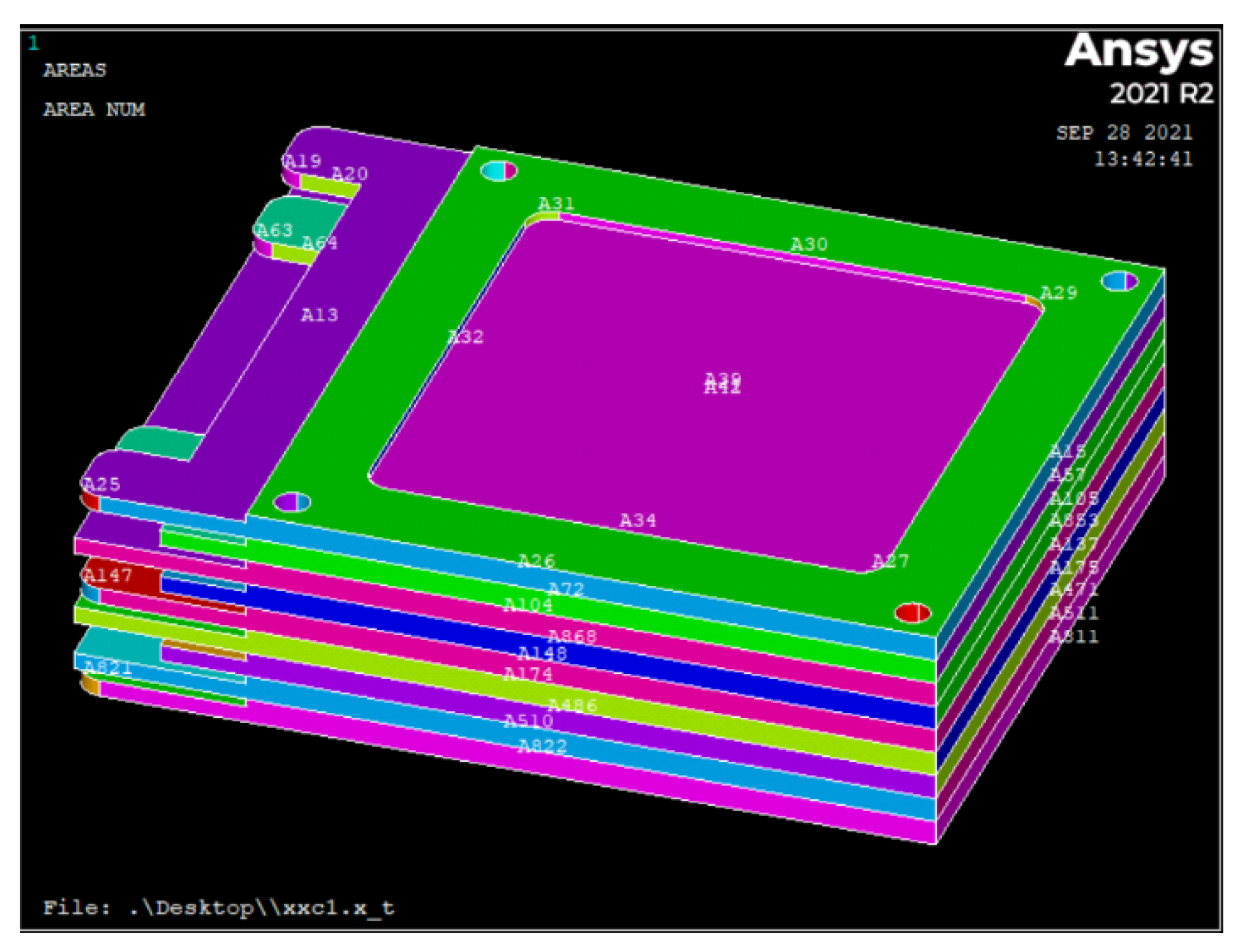
3. Ansys Modeling of Gas Ionization Chamber

This paper optimizes the design process from four aspects: the method for importing the gas ionization chamber ANSYS model, model simplification and setup, regional meshing of the model, and solver selection. This approach significantly saves modeling time for researchers, effectively enhances research efficiency and analysis accuracy, and provides a scientific basis and reference for ANSYS modeling of similar nuclear detectors, electrostatic finite element analysis, and interactive use of ANSYS models with other software. The key step in the improved finite element analysis method lies in the model simplification and setup phase, which includes model partitioning/trimming and the definition of the gas region between the electrodes. The definition of the gas region between the electrodes is the core part.

3.1. Technical Scheme and Approach

To achieve the model establishment and electrostatic finite element analysis for the gas ionization chamber based on ANSYS, this paper adopts the following technical scheme and approach:
Before performing the ANSYS electrostatic finite element analysis of the gas ionization chamber, simplifying and trimming the model, and adding the necessary gas region solid assembly are the core aspects of this technical scheme.
(1) Simplification of the Gas Ionization Chamber SOLIDWORKS Model: The insulating plates between the high-voltage plate and the collecting plates are removed. Since these insulating plates are hollow FR4 frame structures used for insulation, they are not within the electrostatic analysis region and do not participate in the electrostatic field calculation. Therefore, as shown in Figure 4, the model is simplified to reduce unnecessary computational load, improve analysis speed, and save memory and computational resources.
(2) Partitioning of the Gas Ionization Chamber SOLIDWORKS Model:
Since the electrode plate frames of the ionization chamber are made of FR4 insulating material, and the central sensitive region is aluminum film, the originally integrated electrode plate model was improved by partitioning it into regions. This facilitates the assignment of material properties and element attributes, and also benefits the regional mesh design of the model and the accuracy of voltage boundary settings.
Figure 5. Regional partitioning of different materials on the electrode plate.
Preprints 182366 g005
(3) Trimming of the Gas Ionization Chamber SOLIDWORKS Model:
Trimming the gas ionization chamber model is also an important step in model refinement and optimization. As can be seen in Figure 6, the ends of the copper strips within the black frame are embedded into the insulating electrode plate frame. These portions of the copper strips cannot collect electron drift signals, but they still exist as copper strip entities during meshing and calculation analysis, participating in the entire electrostatic finite element analysis setup and calculation process, which significantly increases the number of nodes and the error rate. Therefore, they are trimmed off.
(4) Solidification of the Gas Region in the Gas Ionization Chamber SOLIDWORKS Model:
The solid modeling of the gas region in the gas ionization chamber is the core process of the entire electrostatic finite element analysis. The gas medium fills the spaces between the various electrode plates of the gas ionization chamber and is the site where particle generation and transport occur. Because the gas medium is colorless and formless, it was not included in the original gas ionization chamber model, meaning the gaps between the plates were empty. Performing electrostatic field analysis and calculation with such a model cannot yield the internal electric potential contour plot of the gas ionization chamber or obtain correct analysis results. Therefore, the gas region solid was modeled and added, filling the gaps between each pair of plates, shaped as a rectangular cuboid (as shown in Figure 7).

3.2. Advantages and Innovations

1. Efficient Model Import: Importing the SOLIDWORKS model of the gas ionization chamber into ANSYS via APDL command streams accurately omits the extensive tedious operations and calculations associated with manual ANSYS modeling, significantly improving the computational and modeling efficiency for designers and analysts.
2.Enhanced Software Interoperability: Setting the ANSYS element type for the gas ionization chamber to the electrostatic 3D Brick 122 (curved tetrahedral) type facilitates the import and interaction of the ANSYS model with Monte Carlo platform software like Garfield++. This effectively enhances the research ability and verifiability of the gas ionization chamber ANSYS finite element model.
3. Crucial Gas Region Definition: Defining the solid gas region between the electrodes is a key technical step and innovation of this method. Without defining this gas region entity, obtaining the electrostatic finite element potential contour plot is impossible, and the electrostatic finite element analysis calculation fails to converge. The gas region entity can be assigned various required working gas media properties through the material property settings step, enabling analysis and study of the ionization chamber’s performance characteristics under different gas media. Furthermore, this method provides a basis for setting the gas region entity in other structural types of gas ionization chambers (e.g., cylindrical ionization chambers), where one only needs to create the gas region entity in the actual volume where particle incidence and gas ionization occur.
4. Regional Meshing for Efficiency: Performing regional meshing operations effectively enhances the computational accuracy of the electrostatic field analysis in regions of interest while reducing computational load and resource consumption on irrelevant entities or surfaces.
5. Model Simplification Benefits: Simplifying and trimming the gas ionization chamber model (as shown in Figure 4, Figure 5 and Figure 6) effectively improves the precision of material property assignments, regional meshing settings, and voltage boundary condition applications for the ANSYS model. It reduces the number of output elements and nodes, saves ANSYS computation time, and optimizes the utilization of computational resources to the greatest extent.

4. ANSYS Modeling Process and Steps for the Gas Ionization Chamber

4.1. Experimental and Modeling Steps

(1) Model Import: Before importing the gas ionization chamber SOLIDWORKS model into ANSYS, the SOLIDWORKS model file must be converted into a SOLIDWORKS gas ionization chamber file with the ‘.x_t’ extension. Firstly open the Mechanical APDL 2021 platform. Select ‘File’ from the menu bar, choose ‘Import’ from the dropdown menu, and then select ‘PARA’ – this format corresponds to the ‘.x_t’ SOLIDWORKS file. Select the corresponding gas ionization chamber SOLIDWORKS file to successfully import the model into ANSYS via command streams. The imported model is shown in Figure 8.
The imported gas ionization chamber model is initially crude and numerically unstable, making it unreliable for direct electrostatic finite element analysis in ANSYS. Before proceeding further, it is essential to refine and optimize the model through several critical steps: simplification, trimming, partitioning, and the solidification of the gas region (as illustrated in Figure 4, Figure 5 and Figure 6). These procedures are crucial for enhancing the geometric integrity and numerical stability of the model, thereby ensuring the accuracy and reliability of subsequent simulation results.
(2) Element Type Definition: The first step in ANSYS electrostatic finite element analysis of the gas ionization chamber is to define the element type. A critical consideration when defining the element type is the need for model compatibility with other software platforms if the ANSYS model is intended for subsequent import and interaction with other programs, such as importing into Garfield++ for further analysis in this study. This paper selects the electrostatic 3D Brick 122 (curved tetrahedral) element type for the gas ionization chamber ANSYS model. Failure to use a compatible element type may lead to issues like node overflow, preventing the successful import of the ANSYS model into Garfield++ for software interaction. This method enhances the connectivity and shared usage of ANSYS models with other software, improving research and development efficiency.
(3) Material Property Assignment: In this paper, the material properties for the gas ionization chamber are set as follows: the sensitive region (electrode plates) is aluminum film, the frame is an insulating material, and the high-voltage electrode frame is copper metal. Attention must be paid to the appropriate setting of the dielectric constant and resistivity for the metal materials.
The fundamental principle of the gas ionization chamber involves proton beam incidence ionizing and exciting the gas medium inside the chamber, creating electron-ion pairs. These pairs drift directionally under the influence of the electric field, generating electrical signals at the collecting electrodes. Therefore, the material property settings must also include the definition of the gas region. The gas region is located between each pair of electrode plates in the gas ionization chamber. This is the key technical aspect for obtaining the final electrostatic finite element analysis results. Without this setting, the calculation results will not converge.
(4) Attribute Assignment: After setting the model’s material properties, the corresponding surfaces or solids of the gas ionization chamber must be assigned unit attributes according to the actual physical components. For example, for the gas region, select the corresponding solid region in the model for assignment; for the aluminum film, select the corresponding surface with aluminum material properties, and so on, until all assignments are complete.
(5) Meshing: The meshing step for the gas ionization chamber model is crucial for the finite element analysis, directly affecting the accuracy and speed of the solution. This paper employs regional meshing for the gas ionization chamber model. Critical parts (such as the aluminum film collecting electrodes of the dose ionization chamber and the copper strip collecting electrodes of the position ionization chamber) use a fine swept mesh method. Less critical parts that scarcely participate in the electric field analysis calculation (such as the electrode frames) use the SmartSize meshing method. This approach significantly reduces the disk space required for ANSYS computation and analysis, improves calculation speed and precision, focuses analysis on regions of interest, avoids wasting computational resources, and enhances overall computational efficiency.
Figure 9. Swept mesh results for the copper strips on the collecting electrode plate.
Preprints 182366 g009
(6) Boundary Condition Application: Setting the boundary conditions for the gas ionization chamber model is critical, primarily involving the application of voltage boundaries. Voltage boundaries are applied to the surface nodes of the aluminum film on the high-voltage electrode plate, the surface nodes of the aluminum film on the dose signal electrode plate, and the copper strips of the position signal electrode plates. The collecting electrode plates (dose signal and position signal plates) are set to 0 V, while the high-voltage electrode plate is set to -1000 V.
(7) Solver Selection: After setting the voltage boundaries, select the solver required for the electrostatic finite element analysis calculation of the gas ionization chamber model. ANSYS provides several solvers: Sparse Direct Solver (SPAR), Jacobi Conjugate Gradient Solver (JCG), Preconditioned Conjugate Gradient Solver (PCG), and Incomplete Cholesky Conjugate Gradient Solver (ICCG). Based on the characteristics and applicability of each solver, the Jacobi Conjugate Gradient Solver (JCG) was selected as the solver for the ANSYS finite element electric field analysis of the gas ionization chamber.
(8) Solution and Result Export: The final step is to perform the finite element electric field analysis calculation for the gas ionization chamber model. If the modeling and settings are accurate, the obtained calculation results will converge, yielding the corresponding nodal potential contour plot and convergence diagram for the gas ionization chamber. Conversely, if the results do not converge, the analysis calculation error is significant, indicating poor accuracy and precision in the model establishment. The final electrostatic finite element analysis results can be exported as files containing element node and material property information (`ELIST.lis`), nodal coordinate information (`NLIST.lis`), material resistivity and relative permittivity (`MPLIST.lis`), and nodal voltage boundary constraint results (`PRNSOL.lis`).
These final result files can serve as model data files for import into other platforms for further analysis and use.

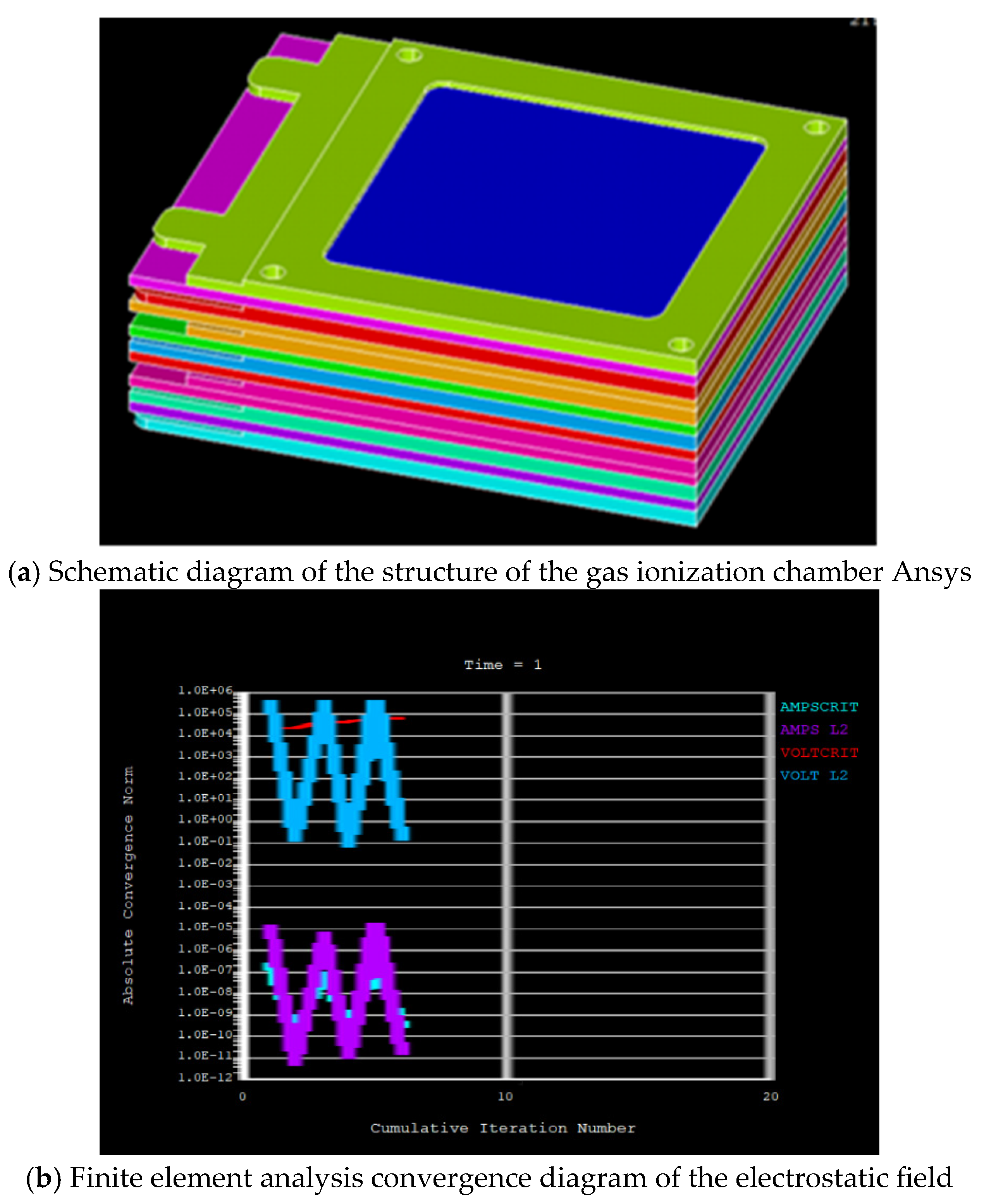
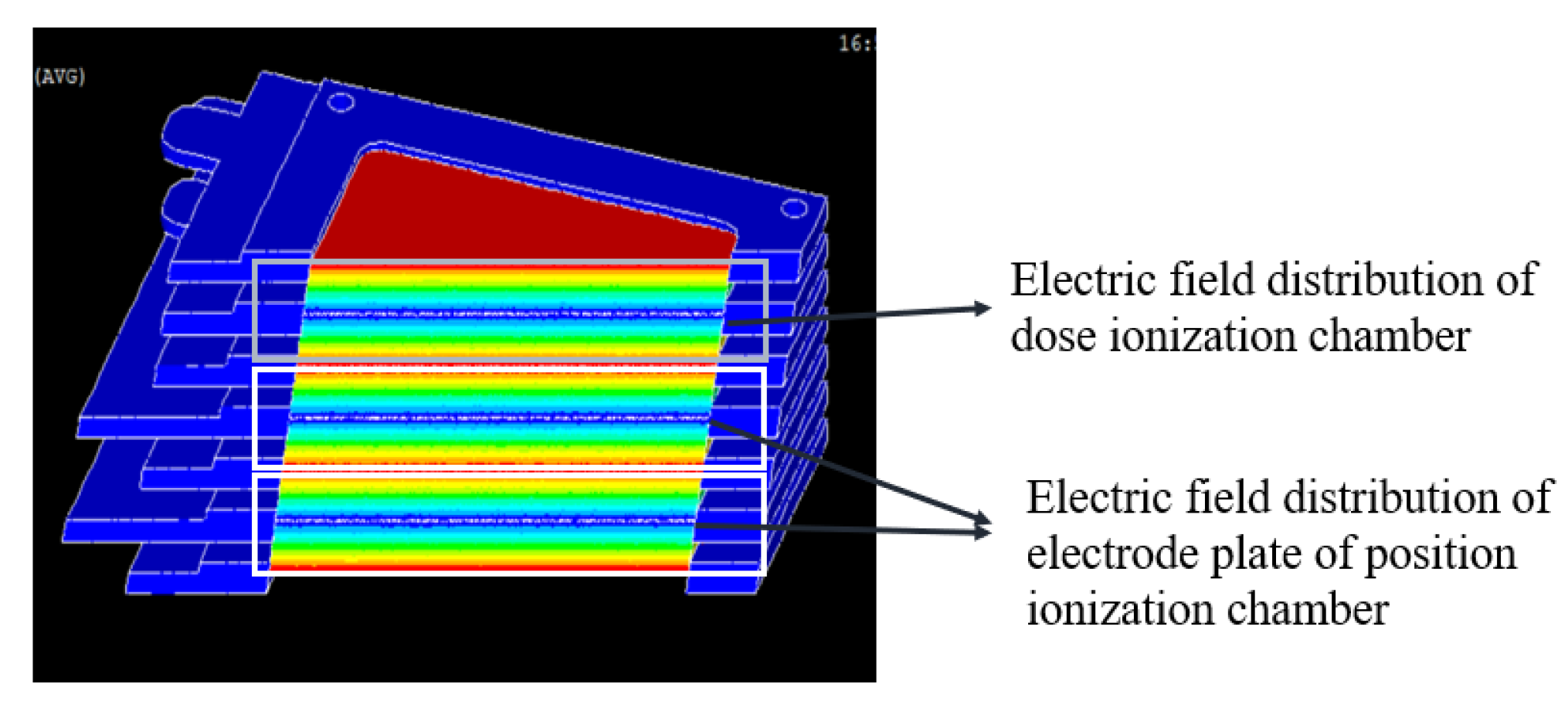
4.2. finite Element Analysis Results of Gas Ionization Chamber

In Figure 10, Figure 10(a) is the ansys modeling graph of the gas ionization chamber, Figure 10(b) is the convergence chart of static electric field finite element analysis results of gas ionization chamber.
The Finite element analysis convergence diagram of the electrostatic field can be shown in Figure10 (b), which is the convergence chart of static electric field finite element analysis results of gas ionization chamber. The AMPS L2 in it is the convergence criteria curve for the current calculation, while the VOLT L2 is the convergence criteria curve for the voltage calculation. The AMPSCRIT is the convergence curve of the actual current calculation of the ionization chamber model, while the VOLTCRIT is the convergence curve of the actual voltage calculation of the ionization chamber model. The abscissa represents the number of iterations, the ordinate represents the absolute convergence norm. If the actual calculated curve’s position is not lower than the convergence standard curve, then the actual calculated curve is conforming to convergence criteria, so as to prove the correctness of the ansys finite element electric field analysis of gas ionization chamber、the accuracy of the of the gas ionization chamber ansys model established、the precisely of the voltage boundary set in the model、the reasonable of the grid division chosen in the model. It lays a reliable foundation for the subsequent import of the model into Garfield++ for simulation.
as to the finite element electric potential cloud diagram in ANSYS model showed in Figure 11, each group of electric fields is divided into two parts, one is the electric field formed by the collecting plate and the upper high-voltage plate (the direction of the electric field is from top to bottom), and the other is the electric field formed by the collecting plate and the off-duty high-voltage plate (the direction of the electric field is from bottom to top).

5. Conclusions

Based on the electrostatic finite element analysis of the gas ionization chamber using ANSYS, the following conclusions are drawn:
1.Model Validity and Convergence: The established finite element model demonstrates excellent convergence in electrostatic field analysis, confirming the accuracy of the geometric structure, material property settings, and voltage boundary definitions. This provides a reliable foundation for subsequent physical simulations and performance evaluations.
2.Innovation in Gas Region Definition: The introduction of a solid gas region between electrodes is a key innovation, ensuring the convergence of electrostatic field calculations and enabling accurate simulation of the ionization process under various gas media conditions.
3.Advantage in Software Interoperability: By adopting the SOLID123 element type and standardized export formats, the model achieves seamless integration with simulation platforms such as Garfield++, enhancing its utility in cross-software collaborative research and verification.
4.Efficiency in Modeling Process: The proposed modeling strategy—incorporating model simplification, regional meshing, and optimized solver selection—significantly improves computational efficiency while maintaining analysis accuracy, offering a practical reference for similar detector simulations.
This study validates the effectiveness of the ANSYS-based electrostatic analysis method for gas ionization chambers and highlights its potential in supporting the design and optimization of beam monitoring systems for laser-driven proton therapy.

Conflicts of Interest

The authors declare no conflict of interest.

References

  1. ZHENG Rongshou, SUN Kexin, ZHANG Siwei, et al. Analysis of the prevalence of malignant tumors in China in 2015 [J]. Chinese Journal of Oncology, 2019, 41(1): 19-28(in Chinese).
  2. Bray F I, Ferlay J, Soerjomataram I, et al. Global cancer statistics 2018: GLOBOCAN estimates of incidence and mortality worldwide for 36 cancers in 185 countries[J]. CA: A Cancer Journal for Clinicians, 2018, 68(6): 394-424.
  3. Liu Shiyao. Status and development of proton therapy equipment[J]. Basic Medicine and Clinical, 2005, 25(2): 123-127(in Chinese).
  4. P. Mulser, D. Bauer, H. Ruhl, Collisionless laser-energy conversion by anharmonic resonance, Phys. Rev. Lett. 101 (2008) 225002. [CrossRef]
  5. T. Ziegler, D. Albach, C. Bernert, S. Bock, F.-E. Brack, T.E. Cowan, N.P. Dover, M. Garten, L. Gaus, R. Gebhardt, I. Goethel, et al., Proton beam quality enhancement by spectral phase control of a PW-class laser system, Sci. Rep. 11 (2021) 7338. [CrossRef]
  6. Z.-C. Yan, W. Nörtershäuser, G.W.F. Drake, High precision atomic theory for Li and Be+: QED shifts and isotope shifts, Phys. Rev. Lett. 100 (2008) 243002. [CrossRef]
  7. H.Y. Wang, C. Lin, Z.M. Sheng, B. Liu, S. Zhao, Z.Y. Guo, Y.R. Lu, X.T. He, J.E. Chen, X.Q. Yan, Laser shaping of a relativistic intense, short Gaussian pulse by a plasma lens, Phys. Rev. Lett. 107 (2011) 265002. [CrossRef]
  8. A.A. Morris, Applications of 10 MeV photons and 100 MeV protons in radiotherapy, 2020, http://dx.doi.org/10.48550/ARXIV.2006.13117, arXiv preprint.
  9. F. Kroll, F.-E. Brack, C. Bernert, S. Bock, E. Bodenstein, K. Brüchner, T.E. Cowan,L. Gaus, R. Gebhardt, U. Helbig, L. Karsch, T. Kluge, et al., Tumour irradiation in mice with a laser-accelerated proton beam, Nat. Phys. 18 (2022) 316–322. [CrossRef]
  10. U. Masood, M. Bussmann, T.E. Cowan, W. Enghardt, L. Karsch, F. Kroll, U. Schramm, J. Pawelke, A compact solution for ion beam therapy with laser accelerated protons, Appl. Phys. B 117 (1) (2014) 41–52. [CrossRef]
  11. U. Masood, T.E. Cowan, W. Enghardt, K.M. Hofmann, J. Pawelke, A light-weight compact proton gantry design with a novel dose delivery system for broad-energetic laser-accelerated beams, Phys. Med. Biol. 62 (13) (2017) 5531–5555. [CrossRef]
  12. F.H. Lindner, D. Haffa, J.H. Bin, F. Englbrecht, Y. Gao, J. Gebhard, J. Hartmann,P.Hilz, C. Kreuzer, S. Lehrack, et al., Towards swift ion bunch acceleration by high-power laser pulses at the centre for advanced laser applications (CALA), Nucl. Instrum. Methods Phys. Res. B 402 (2017) 354–357, http://dx.doi.org/ 10.1016/j.nimb.2017.02.088, Proceedings of the 7th International Conference Channeling 2016: Charged and Neutral Particles Channeling Phenomena.
  13. T.F. Rösch, Z. Szabó, D. Haffa, J.H. Bin, S. Brunner, F.S. Englbrecht, A.A. Friedl, Y.Gao, J. Hartmann, P. Hilz, C. Kreuzer, F.H. Lindner, et al., A feasibility study of zebrafish embryo irradiation with laser-accelerated protons, Rev. Sci. Instrum. 91 (6) (2020) 063303. [CrossRef]
  14. G.A.P. Cirrone, M. Carpinelli, G. Cuttone, S. Gammino, S. Bijan Jia, G. Korn,M.Maggiore, L. Manti, D. Margarone, J. Prokupek, et al., ELIMED, future hadrontherapy applications of laser-accelerated beams, Nucl. Instrum. Methods Phys. Res. A 730 (2013) 174–177, http://dx.doi.org/10.1016/j.nima.2013.05. 051, Proceedings of the 9th International Conference on Radiation Effects on Semiconductor Materials Detectors and Devices.
  15. F. Romano, F. Schillaci, G.A.P. Cirrone, G. Cuttone, V. Scuderi, L. Allegra, A. Amato, A. Amico, G. Candiano, G. De Luca, et al., The ELIMED transport and dosimetry beamline for laser-driven ion beams, Nucl. Instrum. Methods Phys. Res. A 829 (2016) 153–158, http://dx.doi.org/10.1016/j.nima.2016.01.064, 2nd European Advanced Accelerator Concepts Workshop - EAAC 2015.
  16. G. Aymar, T. Becker, S. Boogert, M. Borghesi, R. Bingham, C. Brenner, P.N. Burrows, O.C. Ettlinger, T. Dascalu, S. Gibson, T. Greenshaw, et al., LhARA: The laser-hybrid accelerator for radiobiological applications, Front. Phys. 8 (2020) 567738. [CrossRef]
  17. GSI Helmholtz, ATHENA — Accelerator technology Helmholtz infrastructure, 2022, project website (accessed on 22 April 2022). URL https://www.athena-helmholtz.de.
  18. K.D. Wang, K. Zhu, M.J. Easton, Y.J. Li, C. Lin, X.Q. Yan, Achromatic beamline design for a laser-driven proton therapy accelerator, Phys. Rev. Accelerators Beams 23 (2020) 111302. [CrossRef]
  19. Denker, D. Cordini, J. Heufelder, H. Homeyer, H. Kluge, I. Simiantonakis, R. Stark, A. Weber, Ion accelerator applications in medicine and cultural heritage, Nucl. Instrum. Methods Phys. Res. A580 (1) (2007) 457–461, http://dx.doi.org/ 10.1016/j.nima.2007.05.320, Proceedings of the 10th International Symposium on Radiation Physics.
  20. K.D. Wang, K. Zhu, Matthew J. Easton, Y.J. Li, K. Wang a, X.C. Xie, H.Y. Lan,S.X. Cai, H. Wang, H.L. Ge, T.R. Zhu, J. Li a, C.J. Zhang, X.Y. Zhao, C. Lin,X.Q. Yan, Beam distribution homogenization design for laser-driven proton therapy.
Figure 3. Schematic diagram of the structure of the gas ionization chamber.
Preprints 182366 g003
Figure 4. Simplified model of the gas ionization chamber.
Preprints 182366 g004
Figure 6. Trimming of copper strips embedded at the ends of the insulating electrode plate frame.
Preprints 182366 g006
Figure 7. Solid gas region setup between the plates of the gas ionization chamber.
Preprints 182366 g007
Figure 8. Imported model in ANSYS.
Preprints 182366 g008
Figure 10. Ansys finite element electric field analysis of gas ionization chamber.
Preprints 182366 g010
Figure 11. Finite element electric potential cloud diagram of gas ionization chamber ansys model section.
Preprints 182366 g011
Disclaimer/Publisher’s Note: The statements, opinions and data contained in all publications are solely those of the individual author(s) and contributor(s) and not of MDPI and/or the editor(s). MDPI and/or the editor(s) disclaim responsibility for any injury to people or property resulting from any ideas, methods, instructions or products referred to in the content.
Copyright: This open access article is published under a Creative Commons CC BY 4.0 license, which permit the free download, distribution, and reuse, provided that the author and preprint are cited in any reuse.
Prerpints.org logo

Preprints.org is a free preprint server supported by MDPI in Basel, Switzerland.

Subscribe

Disclaimer

Terms of Use

Privacy Policy

Privacy Settings

© 2025 MDPI (Basel, Switzerland) unless otherwise stated