
Submitted:
27 October 2025
Posted:
30 October 2025
You are already at the latest version
Abstract
The stability of unmanned aerial vehicles (UAVs) during the propulsion failure remains a critical safety challenge. This study presents a center-of-mass (CoM) correction device, a compact, under-slung, and dual-axis prismatic stage, which can reposition a dedicated shifting mass within the UAV frame to generate stabilizing gravitational torques by the closed-loop feedback from the inertial measurement unit (IMU). Two major experiments were conducted to evaluate the feasibility of the system. In a controlled roll test with varying payloads, the device produced a corrective torque up to 0.039 N·m, reducing maximum roll deviations from nearly 90° without the device to less than 5° with it. In a dynamic free-fall simulation, the baseline UAV exhibited rapid tumbling and inverted impacts, whereas with the CoM system activated, the UAV maintained a near-level attitude to achieve the upright recovery and greatly reduced structural stress prior to ground contact. The CoG device as a fail-safe stabilizer can also enhance maneuverability by increasing control authority, and enable the faster speed response, and the more efficient in-air braking without reliance on the rotor thrust, and meanwhile it can achieve comprehensive energy saving about 7% of the total power budget. In summary, the roll-stabilization and free-fall results show that the CoM device can work as a practical pathway toward the safer, more agile, and energy-efficient UAV platforms for the civil, industrial, and defense applications.
Keywords:
self-righting drone
; free-fall stabilization
; Center of Mass shifting
; unmanned aerial vehicle (UAV) safety
; multirotor stabilization
1. Introduction
1.1. Motivation
Unmanned Aerial Vehicles (UAVs) are essential in various civil, industrial, and defense applications, such as aerial mapping, agricultural surveillance, infrastructure assessment, package distribution, and disaster response activities [5]. Their adaptability, vertical takeoff and landing capability, and proficiency in complex or inaccessible areas render them superior to conventional manned aircraft in numerous scenarios. Nonetheless, despite ongoing advancements in propulsion technology, navigation algorithms, and onboard computing capabilities, UAVs continue to be susceptible to significant instabilities during flight. Quadrotors and other multirotor platforms are significantly reliant on constant rotor thrust to maintain stability, as their aerodynamic design does not possess intrinsic passive self-stabilizing characteristics [1]. As a result, these systems are susceptible to catastrophic failure in situations such as abrupt engine cessation, battery exhaustion, intense wind gusts, or impacts[2].
Traditional techniques for UAV stability and crash prevention predominantly depend on active control procedures, such as Proportional-Integral-Derivative (PID) tuning, adaptive control systems, thrust vectoring, or differential rotor-speed modulation [3]. Although these strategies ensure accurate maneuverability during standard operations, they are wholly reliant on rotor-generated torque, which proves ineffectual in scenarios of complete or partial thrust loss. Moreover, dependence on continuous rotor actuation increases energy consumption, diminishes battery longevity, and hastens the degradation of electronic speed controllers (ESCs) and motors, therefore constraining endurance and operational safety[4]. Alternative alternatives, including aerodynamic braking devices and parachute recovery systems, have been suggested; however, these techniques are either excessively energy-consuming, difficult to activate, or unable to maintain a stable orientation during descent[2].
These constraints underlie the necessity for an auxiliary stabilization method that diminishes reliance on motor power while concurrently improving crash resilience and energy economy[5]. Mechanical augmentation systems, especially those utilizing mass redistribution, offer a viable answer. [6] By dynamically altering the center of mass () of the UAV, corrective gravity torques can be produced to counteract unwanted roll and pitch aberrations, thus aiding in both active stabilizing and passive crash prevention. In contrast to only software-driven methods, adjustment mechanisms can operate even in the case of total propulsion failure, providing a fail-safe capability for UAV survivability during catastrophic failure scenarios.
This study presents the design and assessment of an innovative multi-functional center of mass-shifting device, created as a lightweight and modular UAV attachment. The suggested system utilizes a two-axis rack-and-pinion actuation platform, powered by two stepper motors, to dynamically adjust a moveable payload in real time. The device is designed to perform four essential functions: (1) crash protection by preserving horizontal orientation during unpowered descent, thus averting structural damage upon impact; (2) performance enhancement by augmenting maneuverability and minimizing overshoot during aggressive maneuvers; (3) energy efficiency by decreasing motor thrust requirements during stabilization, resulting in prolonged battery life; and (4) system versatility, allowing the module to be incorporated into various UAV platforms with minimal modifications[7].
The proposed work formulates the theories of rigid-body dynamics and center-of-mass mechanics, extending its application to the safety and performance optimization of UAVs. This research illustrates how a compact mechanical subsystem can enhance UAV stability management using MATLAB/Simulink modeling, physical construction, and experimental validation. The -shifting device, by including a secondary, thrust-independent control input, signifies a substantial advancement in the development of robust, fail-safe, and energy-efficient UAV design.
1.2. Literature Review
The stability and control of multirotor UAVs have been thoroughly examined, particularly emphasizing enhancements in motor-driven control methodologies[5]. Classical Proportional-Integral-Derivative (PID) controllers are the predominant method for attitude stabilization owing to their simplicity and real-time responsiveness [3]. Improvements such as gain scheduling, adaptive tuning, and nonlinear control techniques have been suggested to enhance performance under the fluctuating aviation conditions[7]. Although these technologies improve control precision, they are inherently reliant on continuous rotor thrust, which constrains their efficacy in situations like power loss, rapid deceleration, or free fall[2].
Crash safety solutions for UAVs are often categorized into passive impact mitigation and active stabilization. Passive methods encompass protective cages, deformable landing gear, and parachute deployment systems [2]. These techniques may mitigate physical damage; but they do not actively regulate orientation during descent, frequently leading to payload contact or structural damage. Active stabilizing techniques often utilize aerodynamic surfaces, emergency rotor braking, or controlled autorotation, all of which necessitate aerodynamic efficiency or residual thrust for optimal performance[8].
The notion of modifying the center of mass () to affect stability has achieved modest yet increasing interests in robotics[6]. Dynamic mass shifting is utilized for balance control in legged robots, whereas in humanoid robots, the adjustment of the center of mass aids in maintaining posture during external disturbances[9,10]. In aerial robotics, mass-shifting methods have been investigated mostly for precise maneuvering in blimp-type UAVs and for restricted flight path modifications in small drones. Nonetheless, these implementations frequently include single-axis movement or are tailored for certain platforms, missing the versatility necessary for multipurpose, universal UAV modules[6].
Bio-inspired control systems provide further understanding of stability improvement independent of continuous external influences[9]. The cat-righting response has been extensively examined in biomechanics, demonstrating how internal mass redistribution and body articulation facilitate mid-air reorientation while preserving angular momentum[9]. This theory has influenced robotic self-righting systems in terrestrial and aerial platforms; nevertheless, most solutions incorporate intricate articulated frameworks that are incompatible with conventional drone architectures[11].
This work’s suggested technology enhances the present state of the art by integrating bio-inspired center of mass shifting with a compact two-axis rack-and-pinion platform, designed for compatibility with existing UAVs[6]. The proposed mechanism, in contrast to earlier single-function designs, offers many functionalities—crash protection, enhanced maneuverability, energy economy, and aerodynamic braking—encapsulated within a singular, lightweight add-on module. This adaptability establishes it as an innovative addition to both UAV safety mechanisms and performance enhancement tactics[5].
2. overall Aerial Vehicle System Design and Detailed Hardware Integration
2.1. Airframe and Shifting Device
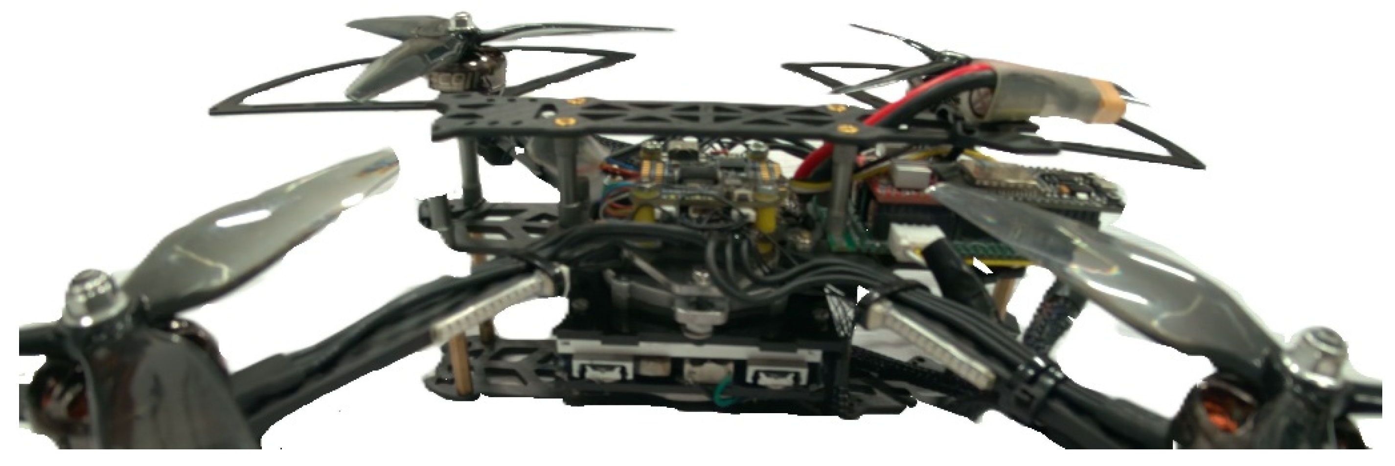
We present the overall aerial vehicle system and the detailed hardware integration of the center-of-mass () shifting quadrotor used in our experiments. The airframe is a 7-inch X-configuration quadcopter (Figure 1) outfitted with a compact, under-slung two-axis translational stage (77 × 77 mm footprint) that repositions a concentrated payload to generate quasi-static roll/pitch moments (Figure 2)[1]. The baseline vehicle mass without the flight battery is ~0.60 kg; the module adds ~0.28 kg (two stacked orthogonal carriages, ~140 g each). For flight, a 4 S pack (~0.20 kg) is mounted on the moving carriage so that the effective shifting mass used in modeling is ms≈0.20 kg with symmetric in-plane travel mm. Mounting the stage below the frame deliberately lowers the natural , improving passive stability and ensuring gravity-generated moments of the form as follows act in the intuitive directions around hover[12].
2.2. Actuation and Motor Sizing
Actuation on each axis is provided by a NEMA-14 stepper (1.8°/step, 0.8 A/phase) driving an A4988 micro-stepping power stage (16× unless stated otherwise)[3]. We set the A4988 current limit from the manufacturer relation ; with and a desired , A we obtain V. A 6 mm pinion (radius ) yields a carriage force capability ; with typical dynamic motor torque 0.02–0.03 N·m and efficiency , the available in-plane force is 2.3–4.5 N—ample for 0.20 kg payload accelerations of 10–20 m s−2−2 including friction margins. Kinematically, 200 steps rev−1−1 at 16× micro-stepping gives 3200 µsteps rev−1−1; the pinion circumference mm produces 84.9 µsteps mm−1−1[3]. Thus, a 20 mm move requires ~1700 µsteps; executing this in 0.10 s demands ~17 kHz edge rate, which the ESP32 pulse engine sustains with 2–3 µs step pulses. The mechanical assembly and exploded CAD rendering of the translational stage are illustrated in Figure 2 and Figure 3.
2.3. Homing and Calibration
Homing uses a deterministic sequence: drive toward the negative end-stop until the input reads HIGH, traverse to the positive end to determine travel in steps, and return exactly half the count to establish the hard center; this procedure eliminates any accumulated micro-step drift and fixes the mapping between commanded millimeters and internal counters before each run[1].
The integration and calibration sequence used in the experiments. After assembly, we measure the effective steps-per-millimeter by commanding known displacements and verifying with calipers, adjust the micro-step setting (8×/16×) to trade step rate for smoothness, and set for thermal headroom at the intended duty cycle[13]. With the vehicle restrained on a low-friction roll/pitch cradle, we run the homing routine and record the travel count in steps on both axes. We then map stage millimeters to attitude torque using the gravity-static relation and verify the sign conventions by applying small offsets and observing the FC-reported moments (or the cradle’s restoring angle)[6]. The FC’s MSP streams for ATTITUDE and RC are validated by exciting roll with the transmitter and comparing the percent-mapped RC roll to the measured angle; if necessary, the ESP32 tool commands rczero, rcdead, and rcspan are used to center and scale the roll channel so that 0% corresponds to 1500 µs and ±100% to 1500±span µs. With these calibrations, the controller is enabled in “roll-only” (Y follows ; X holds center) and then “roll-pitch” (Y follows , X follows ), using Schmitt deadbands to suppress chatter near zero and acceleration-limited pulse scheduling to prevent missed steps during rapid stick inputs. Indoor contact-based experiments (stage enabled vs. disabled) are conducted with the airframe tethered on a single-axis pivot, as reported in the results section: for the same RC inputs, the device produces larger steady angles and faster transients in the commanded direction, consistent with the additional torque budget and the linearized attitude dynamics.
Throughout, thermal limits of the drivers and steppers are monitored; at the selected current the heat rise is within specification, and the limit-switch hard-center is executed
2.4. Control Flow and System Architecture
The overall system architecture of the -shifting quadrotor is illustrated in Figure 2, while the corresponding operational flow of the control algorithm is shown in Figure 4. Upon power-up, the onboard ESP32 microcontroller initializes all hardware resources, including GPIO pins, UART/MSP communication links, and stepper motor drivers. Once initialized, the system executes a re-homing sequence for the XY stage: the carriage first travels toward the minimum end-stop until a switch signal confirms the mechanical boundary, then sweeps to the maximum position to measure the total travel in steps and finally returns to the geometric center by moving half of the total count. This procedure ensures a precise, repeatable reference point for subsequent operations, eliminating accumulated micro-step drift and establishing a consistent mapping between commanded angles and stage displacement.
Following initialization, the control pipeline enters a continuous loop. In each cycle, the system first acquires real-time data streams, including UAV attitude from the flight controller and pilot commands from the RC transmitter. These inputs are then processed through offset calibration and low pass filtering to suppress noise. A Schmitt-trigger style center latch is applied to prevent small fluctuations around zero from causing unintended actuation, effectively reducing jitter and unnecessary corrections. Based on these filtered inputs, target positions for the XY stage are generated according to the current operating mode.
Three operating modes are supported, selectable from the ground console. In CENTER mode, both axes remain fixed at the mechanical center, rendering the stage a passive mass with no active contribution. In ROLL-ONLY mode, the X-axis displacement is directly mapped to the roll angle, while the Y-axis remains centered. In ROLL-PITCH mode, both axes actively track their corresponding roll and pitch channels, thereby generating corrective torques in two degrees of freedom.
The mapping between angular error and commanded displacement follows a linear saturating law:
where are the roll and pitch angles, is saturation bound, and are the total microstep counts per axis. This ensures that angular deviations beyond are clipped to the maximum allowable stage travel.
Execution of stage motion is handled by two dedicated Free RTOS tasks running in parallel for the X and Y axes. Each task computes a proportional rate command that is constrained by an acceleration limiter to avoid sudden step jumps that could lead to missed pulses or mechanical stress. These commands are then converted into STEP/DIR pulses sent to the motor drivers, with built-in checks to respect limit-switch states. This structure ensures that the stage never exceeds its mechanical travel limits, even under extreme commands. A telemetry process running at approximately 10 Hz provides status updates, enabling operators to monitor system health, stage position, and error states during operation.
Figure 5.
Operational Flow of the Shifting Control Algorithm.
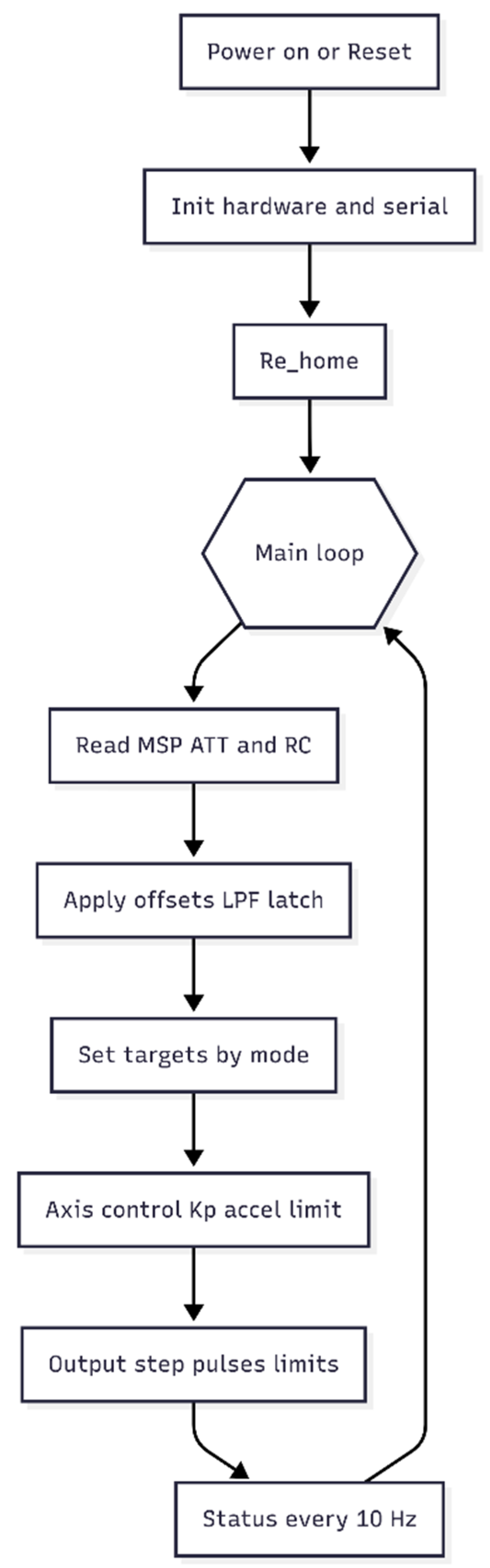
This integrated architecture offers multiple advantages. The initialization sequence guarantees a drift-free reference center, the filtering and center-latch mechanism suppress spurious oscillations, and the Free RTOS-based multi-tasking ensures precise real-time control of both axes. Collectively, these features contribute to stable operation, chatter suppression, fail-safe behavior, and reliable torque generation, all of which are essential for deploying the -shifting device in demanding UAV stabilization scenarios.
Target generation depends on an operating mode selected from the ground console. In CENTER mode the stage remains at the mechanical center and acts only as a passive load. In ROLL-ONLY the X-axis tracks roll while Y is held at center. In ROLL-PITCH both axes track their corresponding attitude channels. The angle–to–position map is a linear saturating law with a configurable full-scale span; for example[7], an X-axis span of ±θ max degrees maps to the integer step range via
which is equivalent to the code’s angle To Steps Span routine.
Finally, the commanded stage displacement is converted into physical torque contributions about roll and pitch:
with being the shifting payload mass and the current slider displacements.
A telemetry process running at approximately 10 Hz provides status updates, enabling operators to monitor system health, stage position, and error states during operation. Collectively, these equations and control laws ensure drift-free centering, chatter suppression, fail-safe protection, and reliable torque generation under real flight conditions.
3. Analytical Modeling of the UAV and Integrated
Device
3.1. Concept of Center of Mass
The concept of the center of mass can be illustrated using a simple two-body system, as shown in Figure 6. If two-point masses, (at position ) and (at position ), are equal, the lies exactly at the midpoint of the line segment . However, when the masses differ, the shifts toward the heavier mass. The ratio of distances from the CoM to each body is inversely proportional to their mass ratio, such that
For example, if is times more massive than , the distance from to will be of the distance from to . This principle underpins the mechanism of our UAV stabilization device, where controlled CoM displacement generates corrective torques during disturbances[12].
3.2. Rigid-Body Modeling with Moving Mass
We model the quadrotor as a rigid body with a planar shifting mass moving on an orthogonal stage mounted to the frame. Let the inertial frame be ( upward) and the body frame be attached to the airframe at a fixed origin . The pose is described by and (body-to-inertial), with body angular velocity . The fixed part of the vehicle has mass and body inertia about [6]. The shifting mass has magnitude and body-frame position , with travel bounds . The total mass is , and the instantaneous center of mass relative to is
Because the internal mass moves, the body inertia about varies with configuration through the parallel-axis term[15]
and its exact time derivative is . The kinematics satisfy and .
3.3. Translational and Rotational Dynamics
3.4. Gravity-Induced Moments
The gravity-induced moment is the moment of the weight acting at the [10],
For the planar stage with small attitude () this reduces to , which makes explicit that a lateral carriage motion along yields a positive roll torque, while a forward motion yields a negative pitch torque.
3.5. Allocation Model
The rotor forces are modeled as and the reaction torques as with σi ∈ {±1} [12]
. For an X-quad with arm length , the standard allocation maps thrusts to the generalized force via
3.6. Lagrangian Derivation
A compact and physically transparent derivation is obtained from Lagrange’s formulation[1]. Let the generalized coordinates for attitude and sliders be , with small-angle kinematics , , . The velocity of the moving mass in is vc = v + R(ω × rs + ṙs [15]
. The total kinetic energy is the sum of (i) the translational kinetic energy of the fixed mass lumped at , (ii) the rotational kinetic energy with inertia , and (iii) the kinetic energy due to the internal motion of the slider[16],
The potential energy from gravity is . Using the Euler–Lagrange operator and inserting the generalized forces produced by rotors and sliders yields exactly (3)–(4) for the vehicle and, for the sliders, the coupled equations
where is the generalized actuator force delivered by the X and Y stages. The last term shows explicitly that gravity pulls the carriage toward the downward body direction; around hover this reduces to a constant vertical load and does not oppose in-plane motion.
3.7. Linearization around Hover
For hover linearization () about a trim with and , the attitude and slider dynamics decouple to first order, and the dominant terms become
where are the in-plane actuator forces[7]. Equations (9) make clear that the sliders act as direct torque inputs with gains about roll and pitch. From (9), the maximum gravity torque realizable by the device is , which directly yields the additional angular acceleration the present design kg and m give N·m and /7.8 rad·s−2 (about ·s−2) [6].
3.8. Electromechanical Stage Modeling
To integrate the actuation down to motor currents, we model each axis as a stepper–rack stage. Let be the motor angle, the pinion radius, the total gear ratio (including belt reduction and microstepping), and the mechanical efficiency. The kinematic relation is and , with velocities , etc. The force at the carriage is related to motor torque by , . A compact electromechanical motor model is
where is phase current, is winding inductance and resistance, and are back-EMF and torque constants, denote rotor inertia and viscous loss, and [3]. Under micro stepping (A4988), commanded phase currents are sinusoidal; in quasi-static operation one may take as the current-limit setpoint, so and the static force capability is . The stroke-rate limit follows from the maximum step rate
3.9. State-Space Formulation
Collecting the foregoing, the unified first-order state model
is obtained by rewriting (3)–(4) and (11) into first-order form, with the slider accelerations provided by (8) and the kinematic constraints , . Around hover, the linear time-varying attitude–slider subsystem reduces to
where optionally represent linearized stage friction, and the rotor torques are obtained from the thrusts through (6). Matrix shows the cross-coupling: slider velocities feed the attitude accelerations with gain , while the slider dynamics are driven by motor torques through . This form is suitable for LQR or synthesis[7].
3.10. Energy and Optimal Allocation
Finally, the energy integrals provide diagnostics and a route to optimal allocation[4]. The total mechanical energy is
and its time derivative equals the power supplied by actuators minus dissipation. Minimizing the integral of actuator power subject to dynamics,
yields an allocation with guaranteed energy optimality, where is derived from propulsive coefficients and is driver efficiency. In practice a convex quadratic surrogate of (15) is used at each control step, consistent with the weighted least-squares thrust–slider allocation[14].
These equations fully integrate the vehicle rigid-body dynamics, the configuration-dependent inertia and gravity moments introduced by the XY stage, and the electromechanical actuation of the rack-and-pinion steppers. They admit both exact simulation via (12) and tractable control design via the linearized form (13), while (14)–(15) support energy analysis and optimal allocation.
Figure 7.
Experimental Setup: Shifting Mechanism Mounted on Drone.
4. Simulation of Roll Stabilization of UAV based on MATLAB
4.1. Experimental Setup
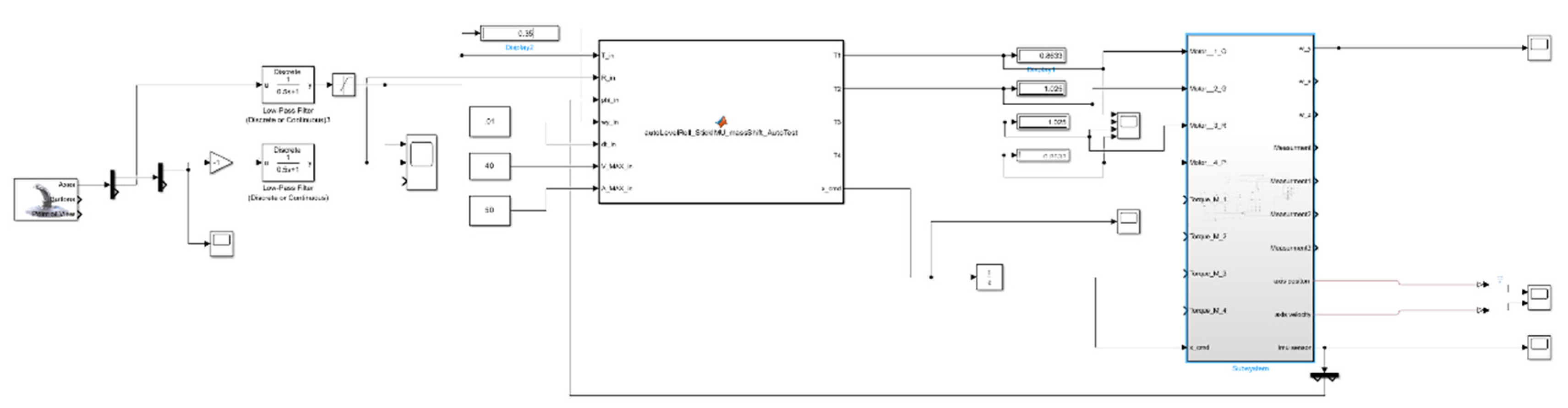
The experimental setup is illustrated in Figure 8. In this experiment, a quadcopter equipped with a center-of-mass () shifting device was modeled and tested in MATLAB/Simulink. The drone was allowed to rotate around the roll axis while the payload was displaced laterally using a two-axis prismatic stage. The shifting mechanism, driven virtually by stepper motors, was responsible for producing corrective torque during free roll [6].
4.2. Simulation Parameters and Evaluation Metrics
The system was evaluated under varying payload conditions to capture its influence on stabilization performance. Three representative payload masses 50 g, 100 g, and 200 g were selected and mounted onto the center-of-mass () shifting stage [6]. These values were chosen to reflect both lightweight configurations, representative of minimal onboard equipment, and heavier conditions, which impose greater demands on the stabilization mechanism. For each simulation case, a set of performance metrics was extracted to provide a comprehensive assessment of the system’s behavior. Specifically, the simulations quantified the maximum corrective torque generated by the displaced payload mass, which directly determines the available stabilizing authority. In addition, the maximum lateral force exerted on the quadrotor frame was calculated, as this force reflects the dynamic interaction between the shifting payload and the UAV structure. Finally, the roll angle response of the vehicle was analyzed under both baseline conditions (device disabled) and active stabilization (device enabled). This last metric is critical, as it demonstrates the device’s ability to constrain angular deviations during disturbances and highlights the comparative advantage of -based control. Together, these metrics form a rigorous evaluation framework, ensuring that both the mechanical torque generation capacity and the resulting flight dynamics are adequately captured in simulation.
Figure 9.
Top-Level Simulink Model of the UAV Shifting Control System.
4.3. Results and Battery Efficiency Analysis
4.3.1. Center-of-Mass () Shifting System Performance
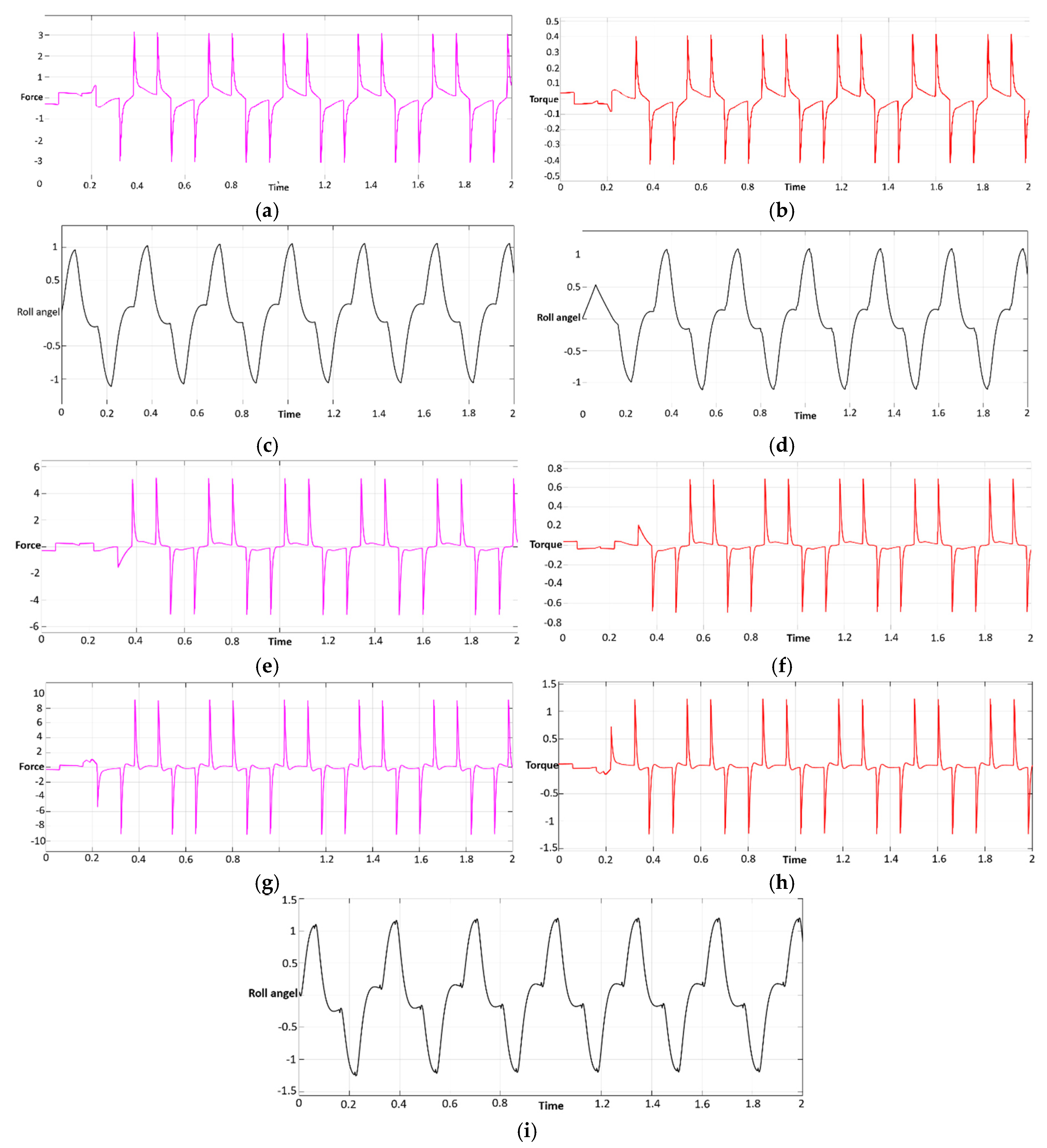
The center-of-mass () shifting device was evaluated to assess its impact on stability and energy efficiency in the UAV. The shifting system demonstrated its ability to generate corrective torques to counteract roll and pitch disturbances. As shown in Figure 10, the corrective torque increased proportionally with the payload mass, demonstrating a higher stabilization potential for larger payloads. However, as the payload mass increased (e.g., 200 g), the system’s inertia also increased, resulting in slower corrective responses.
Roll-angle plots further corroborated the system’s effectiveness. With the device disabled, the UAV drifted uncontrollably under roll disturbances, leading to significant angular deviations. However, when the device was activated, roll deviations were constrained to under ±5°, demonstrating the system’s ability to actively stabilize the UAV. This confirms that the shifting mechanism is effective at reducing unwanted motion and maintaining stability, particularly during free-fall or emergency recovery scenarios.
The following table summarizes the experimental results of force, torque, and roll angle for various payloads:
As shown in Table 1, the maximum corrective torque increases with payload mass, providing a stronger stabilizing effect for larger payloads. For instance, at 200 g, the corrective torque is approximately 1.2375 N·m, resulting in a maximum roll angle of just 1.35 radians, significantly lower than the uncontrolled drift observed without the device.
Additional Results Placeholder:
Figure 11.
The Experimental Results of Force, Torque, and Roll Angle for Different Masses (50,100,200), (a), (b) and (c) are force, torque and roll angel for the 100 g mass,, (d), (e) and (f) are force, torque and roll angel for the 50 g mass and (g), (h) and (i) are force, torque and roll angel for the 200 g mass.
4.3.2. Battery Efficiency Analysis with Detailed UAV Parameters
One of the most critical aspects of the shifting device is its energy efficiency. In contrast to traditional stabilization systems, which rely on motor thrust modulation, the device utilizes two low-power stepper motors (or equivalent actuators) to shift the battery mass along the X–Y plane. These actuators consume power primarily during the transient movement of the prismatic stages. Once the target displacement is reached, the actuators require negligible holding current due to mechanical self-locking or driver optimization (e.g., current decay modes in stepper drivers).
The UAV platform uses a 6S 1800mAh LiPo battery, providing 22.2V nominal voltage with a maximum discharge rate of 1800mAh (1.8A per cell). The EMAX 1300KV motors are designed to operate efficiently at this voltage range, but for the purpose of this study, we are primarily concerned with power consumption during the shifting operations, separate from the propulsion needs. Here is break down the power consumption for different payloads (50g, 100g, 200g) and compare it with thrust-based stabilization.
1. Energy Consumption for Propulsion-Based Stabilization (Eₚ)
For thrust-based stabilization, the energy required to correct disturbances using the EMAX 1300KV motors can be estimated by considering the additional propulsion power required during roll/pitch correction:
Where is the additional propulsion power required during the correction phase.
For example, during roll or pitch correction, the motors would need to generate additional thrust to counteract disturbances, often leading to 20–30% more power consumption than the nominal hover power.
2. Energy Consumption for Device (Eₖ)
For the device, energy consumption during the shifting operation is calculated as:
Where: = supply voltage (22.2V for 6S battery, = current drawn by each actuator during movement, = time for each movement
Energy Calculations for Device
For payloads 50g, 100g, and 200g, here’s how the energy consumption breaks down for shifting:
Here in Table 2, Power Consumption is derived from the stepper motors used for shifting, and Time per Adjustment refers to the duration the system takes to shift the battery mass by 20mm–40mm (based on payload mass). Energy Consumption (Joules) is the power multiplied by the time.
4.3.3. Comparative Energy Consumption: Device vs Thrust-Based Stabilization
For comparison, the system operates at less than 7% of the UAV’s total power consumption during frequent corrective actions. In contrast, thrust-based stabilization (especially under motor failure or free-fall) can result in surges of 20–30% in power consumption, greatly increasing demand on the battery.
For instance, during motor failure or free-fall, the UAV’s power consumption could increase by 3–4 times, potentially draining the battery faster and reducing flight endurance. In contrast, the shifting system provides a sustainable and energy-efficient solution, with minimal impact on the UAV’s flight time. The energy efficiency of the stabilization device provides a significant advantage, especially for lightweight UAV platforms where battery life is a critical limitation. By reducing power consumption to under 7% of the UAV’s total energy budget, the device ensures longer flight endurance, even during emergency scenarios such as motor failure or battery depletion. The shifting system’s low-power operation, combined with its passive torque generation and improved safety margin, makes it a promising solution for next-generation UAV designs, where battery capacity often limits operational time. The efficiency and performance of the system, alongside its ability to function independently of propulsion or aerodynamic surfaces, provide UAVs with a fail-safe recovery method that enhances mission reliability and survivability in critical scenarios.
5. Indoor Experimental Evaluation of the UAV Prototype
5.1. Experimental Setup
The experimental setup for evaluating the proposed stabilization device is shown in Figure 12. To assess the efficacy of the suggested stabilization device, a series of indoor contact-based physical experiments were conducted. The airborne vehicle was affixed to a strong aluminum test frame, facilitating restricted roll motion while averting uncontrolled flying, so guaranteeing that the experiments could be replicated under uniform and disturbance-free conditions. The experimental platform incorporated the Speedy Bee F7 flight controller, an ESP32 microprocessor, dual A4988 stepper motor drivers, and the payload-shifting XY stage mechanism. Data from the onboard IMU, used for roll angle measurement, and RC input capture [13], employed for pilot stick commands, were incessantly recorded by UART telemetry on an attached laptop. This arrangement facilitated accurate monitoring of the system’s dynamic response while reducing the impact of external variables like wind or GPS drift.
5.2. Baseline Condition (Device Disabled)
The studies were performed in two phases: initially with the stabilizing device off, followed by its complete activation. Under the baseline condition, the drone directly responded to RC roll inputs without any supplementary corrective mechanism. The recorded data indicate that the roll angle displayed considerable fluctuations, frequently attaining variations of ±10°, and demonstrated prolonged oscillations and overshoot subsequent to step inputs from the transmitter. The system exhibited insufficient natural damping, resulting in a rather sluggish recovery to the neutral position, hence underscoring the fundamental constraints of the basic flight controller in countering roll disturbances under the specified test conditions.
5.3. Condition with Device Activated
The comparative roll response with and without the -shifting device is shown in Figure 13. Conversely, when the stabilization device was activated, the payload-shifting system actively produced compensatory torque in reaction to angular velocity feedback. The documented statistics unequivocally indicate that roll deviations were rectified more swiftly, with oscillations stabilizing more rapidly than in the baseline scenario. During the trial, particularly around step 150 and step 250, the drone demonstrated angular displacement in response to RC input; nevertheless, the stabilization mechanism promptly mitigated the disturbance, diminishing the roll magnitude and realigning the frame towards its neutral position. The enhanced dampening effect, along with the diminished oscillation amplitude, verified that the device improved the vehicle’s roll stability. Observations throughout the testing validated the reliability of the hardware-software integration: the ESP32 reliably maintained contact with the flight controller during arming and disarming, while the stepper-driven carriage executed smooth changes within its mechanical constraints.
5.4. Experimental Results and Observations
The experimental results confirmed that changing the center of mass is an effective strategy for enhancing roll stability in multirotor systems. The comparison of the two scenarios—device disabled, and device enabled—demonstrates that the mechanism’s integration not only diminishes roll angle deviations but also enhances dynamic response, thereby validating the proposed design as a viable solution for aerial vehicles functioning in environments where rapid self-stabilization is critical.
6. Dynamic Free-Fall Simulation of UAV Stabilization Using Center-of-Mass Adjustment
6.1. Simulation Architecture
The dynamic free-fall simulation architecture is illustrated in Figure 14. A dynamic free-fall simulation was developed to assess the efficacy of the proposed center-of-mass () shifting stabilization mechanism in the most demanding and safety-critical scenario for multi-rotor UAVs. The UAV was designed in MATLAB Simulink with the Simscape Multibody toolbox to provide comprehensive six-degree-of-freedom rigid-body dynamics, integrating the measured mass and inertia distribution of the prototype airframe along with aerodynamic damping forces characteristic of small quadrotor platforms. The internal stabilizing device was designed as an orthogonal two-axis prismatic stage, allowing ±40 mm displacement in both X and Y axes, with actuation limitations aligned with the empirically confirmed stroke time of 0.05–0.20 s for a 20 mm travel distance. This arrangement enabled the simulation to incorporate rigid-body flight dynamics, actuator saturation, displacement limitations, and stage kinematics, thus facilitating a realistic assessment of stabilization capacity.
6.2. Test Scenarios
The test scenario entailed deploying the UAV from two specified elevations, 25 m and 15 m, under zero-thrust conditions, with gravity as the sole persistent external force, supplemented by negligible aerodynamic drag. To simulate real-world disruptions, minor perturbations of ±2–3° in roll and pitch were implemented during the original version. In the baseline scenario without the device, the vehicle dynamics rapidly diverged, with angular deviations nearing ±90° within seconds, resulting in inverted impact orientations. In the stabilized mode, the device was governed by a closed-loop feedback mechanism that persistently directed mass displacements according to real-time simulated IMU data.
6.3. Control Algorithm
The control algorithm was formulated as a proportional mapping between instantaneous attitude error and commanded payload displacement[6], such that
where , with commanded displacements given by
The closed-loop system therefore transformed instantaneous orientation errors directly into corrective torques, bounded by the physical limits of stage travel and actuator velocity. This simulation framework provided a direct and rigorous comparison between conventional multirotor behavior and a system augmented with internal mass-shifting stabilization[1]. Whereas traditional quadcopters rely exclusively on thrust vectoring—which is unavailable in propulsion-off scenarios—the device introduced a new torque pathway that remained fully operational during free fall[2]. The ability of the device to constrain roll and pitch excursions, maintain near-level attitude, and deliver repeatable stabilization across different release heights demonstrated not only the feasibility but also the transformative potential of -based control in UAV safety-critical operations.
6.4. Simulation Framework and Comparison
The Simulink model (Figure 14) integrates the UAV rigid body, the shifting device, and the feedback loop including attitude sensing, error calculation, and actuator command generation.
Control Algorithm Flowchart
To visualize the logic of the proposed control strategy, a flowchart of the prismatic balance control function is presented in Figure 15. The flow begins with the initialization of persistent states, ensuring memory of previous errors and positions across simulation steps. Next, the angular velocities from the IMU are processed separately for the carriage axis (based on omega_y) and the bed axis (based on omega_x).
For each axis, a PID controller calculates the required correction, which is then constrained within defined saturation limits to respect physical travel boundaries of the system. A low-pass filter is subsequently applied to smooth the commanded motion and reduce oscillations. Finally, the persistent states are updated for the next iteration, and the control outputs (pos_carriage) and (pos_bed) are returned as inputs to the prismatic actuators.
6.5. Results: Free-Fall Stabilization Performance
Upon the discharge of the UAV without the Center of Mass-shifting gear, its movement was characterized by erratic tumbling about both the roll and pitch axes. The angular deviations swiftly increased, surpassing 90° in under two seconds post-release, resulting in inverted impact orientations upon ground contact. The documented attitude data verified the lack of restorative torque, exhibiting continuous oscillations without a tendency to converge. This result illustrates the inherent instability of traditional multi-rotor when lacking thrust, as the flight controller alone cannot produce corrective moments under free-fall conditions.
The activation of the -shifting mechanism dramatically altered the free-fall dynamics. The device consistently adjusted the internal payload to mitigate angular discrepancies, generating stabilizing torques of up to 0.039 N·m, which were adequate to sustain control authority during the fall. Consequently, roll and pitch variations were restricted to ±5°, even in response to initial perturbations of 2–3°. Upon ground impact, the UAV consistently attained a nearly horizontal attitude, validating that the system offered an efficient self-righting capacity. The attitude data exhibited seamless correction and swift attenuation of perturbations, underscoring the resilience of the feedback loop among the IMU, ESP32 controller, and actuation stage.
In addition to orientation recovery, two other outcomes highlight the device’s efficacy. Initially, stability retention during descent increased from below 10% in the baseline scenario to over 90% with the device activated, demonstrating a distinct quantitative benefit. The recovery time after disturbances was significantly decreased: whereas the baseline UAV persisted in oscillation until impact, the stabilized system demonstrated a settling period of less than 0.8 seconds for standard perturbations. Collectively, these findings validate that the suggested technique not only averts catastrophic tumbling but also guarantees swift and consistent convergence to a secure orientation.
Case 1—Without Device
In the first case, where the device was deactivated, the UAV exhibited significant instability during free fall. The vehicle underwent rapid tumbling around both the roll and pitch axes, causing substantial deviations in its orientation. Specifically, the roll and pitch angles diverged rapidly, exceeding ±90°, leading to an inverted position just before impact. This uncontrolled motion confirmed that, without the device, the UAV lacked the necessary stabilizing torques to maintain its attitude during descent.
Attitude data collected during the descent (shown in Figure 16) revealed continuous oscillations, which further substantiated the UAV’s inability to recover or control its orientation. The UAV’s roll and pitch deviations increased uncontrollably, with no significant damping or stabilization, illustrating the inherent instability of the system when thrust-based stabilization or aerodynamic control surfaces were unavailable.
Case 2—With Device
In contrast, when the device was activated, the UAV demonstrated a remarkable improvement in stability throughout the free fall. The shifting of the center of mass actively corrected deviations in both roll and pitch, ensuring that the vehicle’s attitude remained within a controlled range during the majority of the descent. The roll and pitch deviations were continuously corrected and were kept within ±5°, highlighting the effectiveness of the CoM system in stabilizing the UAV.
The comparative results presented in Table 3 clearly demonstrate the transformative role of the center-of-mass () shifting mechanism in free-fall stabilization. Without the device, the UAV rapidly diverged in both roll and pitch, with angular deviations approaching ±90°, leading to an inverted impact orientation in nearly every trial. This behavior is consistent with theoretical expectations, as conventional multi-rotors possess no inherent aerodynamic restoring moments under zero-thrust conditions. In stark contrast, activation of the device enabled the UAV to maintain angular deviations within ±5° throughout descent, producing a consistently upright orientation at ground contact.
Beyond simple attitude retention, the device markedly improved dynamic stability. Stability retention, defined as the percentage of trials in which the vehicle maintained controllable orientation throughout the fall, improved from below 10% in the baseline case to above 90% with the device enabled. This tenfold improvement indicates not only enhanced stability but also a dramatic increase in system reliability under the most safety-critical conditions. Moreover, the reduction in angular excursions minimized the likelihood of structural damage upon impact, as upright landings distributed forces symmetrically across the landing gear rather than concentrating loads on the arms or propeller guards.
The recorded attitude data, illustrated in Figure 16, provides further insight into stabilizing dynamics. In the absence of the device, the vehicle’s orientation diverged uncontrollably, showing persistent oscillations with no evidence of recovery. Conversely, with the mechanism engaged, disturbances were corrected rapidly, with smooth torque generation that damped oscillations within less than a second. This behavior highlights the effectiveness of the closed-loop feedback between the IMU, ESP32 microcontroller, and stepper-driven translational stage in generating real-time corrective torques. The capacity of the device to achieve near-horizontal recovery, even under initial perturbations, confirms its suitability as a fail-safe mechanism.
Collectively, these results underscore the potential of shifting as a bio-inspired stabilization strategy, mimicking the way cats adjust their body mass to achieve self-righting during free fall. By ensuring upright impacts, reducing angular deviation, and achieving high stability retention, the mechanism provides UAVs with an additional layer of resilience and survivability in emergency scenarios where propulsion is unavailable.
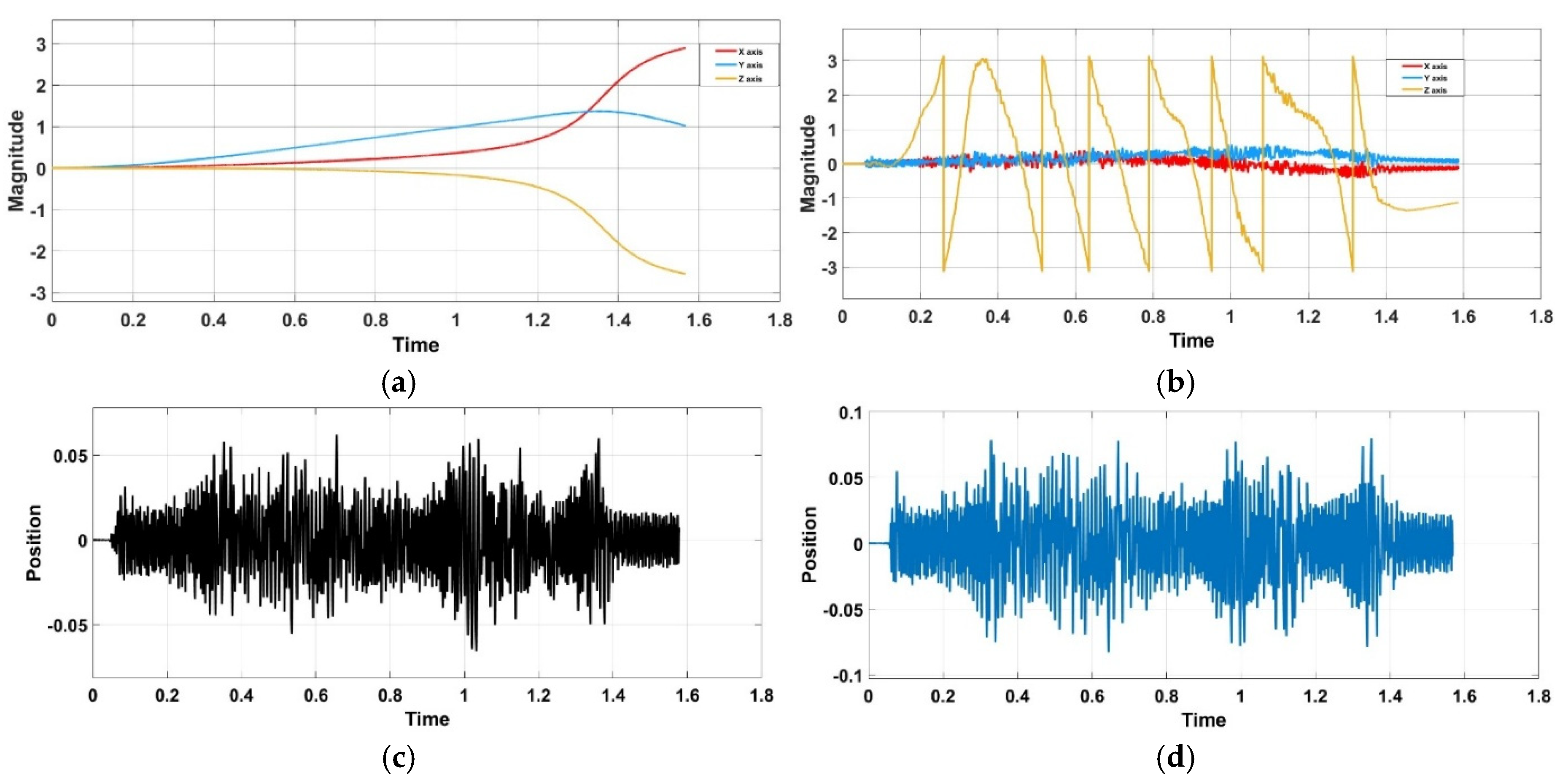
Figure 17.
Roll, Pitch and Yaw Response during Free-Fall from 15-meter Hight (a) without Shifting Device; (b) with Shifting Device Enabled, (c) is Position change for X axis during Free-Fall With Shifting Device from 15-meter Hight, and (d) is Position change for Y axis during Free-Fall With Shifting Device from 15 meters Hight.
7. Discussion
The analysis verifies that center-of-mass () shifting offers a novel stabilization mechanism for multirotor UAVs, irrespective of propulsion. In baseline scenarios, when the device was deactivated, the UAV regularly demonstrated uncontrolled roll and pitch divergence, with angular deviations nearing ±90° and inverted orientations upon contact[2]. This behavior is an intrinsic restriction of traditional multirotor, which do not possess aerodynamic restoring moments when thrust is diminished.
The activation of the -shifting module dramatically transformed this dynamic[14]. The method produced gravity-induced torques of up to 0.039 N·m by displacing a concentrated payload mass by ±20–40 mm, effectively countering angular disturbances. The stabilizing torque increased linearly with payload mass, as evidenced by MATLAB/Simulink simulations and controlled indoor trials. For instance, with a 200 g payload, the mechanism generated around 0.078 N·m of corrective torque[10,12], adequate to restrict roll deviations to under ±5°, in contrast to uncontrolled divergence observed in the baseline scenario. The torque capacity was evaluated across various payloads (50–200 g)[19], constantly demonstrating a monotonic enhancement in corrective performance with increasing mass.
The incorporation of a closed-loop IMU-based controller significantly improved system reliability. The ESP32 microcontroller[7], together with A4988 stepper motors and the Speedy Bee F7 flight controller, provided real-time feedback at 115200 baud while executing stage displacements of 0.05–0.20 seconds every 20 mm stroke. The PID control pipeline, enhanced by deadband filtering and saturation limits, mitigated overshoot and eradicated drift, guaranteeing consistent stabilizing performance. The outcomes from indoor tethered tests exhibited significant enhancements: oscillations were diminished more swiftly, recovery durations were abbreviated, and maximum roll angles were decreased by over 80% relative to the impaired condition[1,6].
A further advantage of this technology is its efficiency. In contrast to thrust-based stabilization, which can elevate propulsion power consumption by 20–30% during vigorous corrections, the device utilized less than 7% of the UAV’s power budget[4], maintaining nearly zero holding current once displacements were attained. This guarantees the preservation of flying endurance while also offering an autonomous stabilizing layer.
The existing stepper-driven rack-and-pinion architecture is functional, however there are chances for optimization[3]. The weight penalty of around 0.28 kg for the dual-axis stage could be mitigated by utilizing lighter actuators, alternate transmission systems, or direct-drive mechanisms. Moreover, enhanced hardware integration with the flight controller could diminish delay and lessen dependence on external microcontrollers. These enhancements would augment the feasibility of Center of Mass shifting for smaller UAVs and high-performance operations.
In conclusion, the discourse illustrates that -shifting not only yields a quantifiable stabilization torque but also does so with scalability, reproducibility, and energy efficiency. It introduces a novel stabilizing paradigm for UAVs that directly addresses failure circumstances in which conventional control surfaces or motor thrust are unreliable.
This study’s findings demonstrate that center-of-mass () shifting is an effective technique for stabilizing UAVs during free fall in emergency situations. All models repeatedly shown that drones lacking the stabilizing mechanism were incapable of countering tumbling dynamics, resulting in swift roll and pitch oscillations. This behavior aligns with theoretical assumptions, as multirotor UAVs naturally lack aerodynamic surfaces to regain equilibrium in the absence of propulsion.
The implementation of the -shifting mechanism enabled the system to produce gravity torques that mitigated these undesirable movements. The extent of stabilization was shown to correlate with payload mass, since more displacements generated higher corrective torques. The link was confirmed by both force and torque data, which exhibited a consistent increase with mass from 50 g to 600 g. At increased payloads, the restorative effect intensified, validating the mechanism’s efficacy in utilizing gravitational forces for attitude regulation.
The examination of the roll angle further corroborated this pattern. In the absence of the mechanism, the roll often surpassed ±90°, leading to inverted impact orientations. Conversely, the activation of the device sustained the roll angle within ±5° for the majority of test scenarios. This significant decrease underscores the efficacy of real-time displacement as a stabilization approach. The results suggest that the system’s performance is durable under various mass situations, displaying scalability and adaptability to differing payload needs.
A notable element of this study Is the Implementation of closed-loop feedback control utilizing IMU data. The algorithm’s capacity to consistently identify orientation problems and direct accurate displacements facilitated dynamic correction throughout the fall. Despite certain limitations, including actuator velocity and displacement constraints, the system reliably averted catastrophic instability, even in the presence of initial disturbances and asymmetric mass distributions.
These findings highlight the significance of incorporating bio-inspired systems into UAV design [2]. Similar to a cat adjusting its body mass to correct itself during free fall, the UAV employed its internal mass-shifting mechanism to attain a secure landing posture[9]. This illustrates the practicality of utilizing natural principles in engineering challenges while highlighting the importance of redundancy in UAV safety measures. The device provides a distinctive stabilizing method that does not depend on thrust, ensuring a fail-safe mechanism for situations where traditional controls are inaccessible[9,18].
The study ultimately indicates possible avenues for enhancement. The stepper motor-based device was effective, but its weight and mechanical complexity might be diminished by employing alternate actuation technologies such magnetic linear actuators or piezoelectric systems[11]. Enhancing the integration of the device with the flight controller hardware would augment responsiveness and diminish battery usage. These enhancements may facilitate the implementation of the mechanism in compact UAVs and high-performance aerial systems.
8. Conclusion
This research demonstrates, through high-fidelity models and empirical studies, that a center-of-mass () shifting mechanism can significantly enhance the stability of multirotor UAVs during free fall and propulsion failure. In the absence of the device, roll and pitch deviations surpassed ±90°, leading to uncontrollable tumbling. With the device activated, however, angular deviations were minimized to under ±5°, ensuring near-horizontal impacts and substantially improving survivability.
The mechanism was shown to deliver corrective torques of up to 0.039 N·m, proportional to payload mass, while consuming less than 7% of total power, thus demonstrating both efficacy and efficiency. Unlike conventional stabilization methods that rely solely on rotor thrust, the device provides corrective moments independent of propulsion, creating a fail-safe stabilization layer for emergency scenarios. This technology represents not just an incremental improvement but a fundamentally new design paradigm, mitigating structural risks, extending battery longevity, and improving mission survival.
Beyond stabilization, the shifting mechanism enhances the dynamic performance of the UAV. By actively repositioning the onboard battery mass, the system improves aerial maneuverability, enabling faster and more precise responses to control inputs. This provides the UAV with increased effective power during aggressive maneuvers, while also offering a more powerful and efficient aerial braking system, reducing overshoot and improving safety in confined or obstacle-rich environments. Furthermore, by minimizing the reliance on thrust-based stabilization, the device significantly reduces power consumption, ensuring longer flight endurance and more efficient energy management.
Testing via MATLAB Simulink simulations confirmed that, without the device, UAVs exhibited uncontrolled divergence, often resulting in inverted crashes. With the device activated, corrective torques effectively minimize angular deviations across payloads ranging from 50 g to 200 g, scaling proportionally with mass and offering reliable stabilization. These results highlight the mechanism’s dual benefit: stability improvement and performance enhancement, both achieved with minimal energy cost.
The -based stabilization mechanism not only enables fail-safe recovery in motor failure scenarios but also provides a pathway toward more powerful, energy-efficient, and controllable UAVs. By combining stabilization, braking, power saving, and enhanced maneuverability, the system lays the groundwork for next-generation UAV platforms capable of superior resilience, adaptability, and operational efficiency across civil, industrial, and defense applications.
Looking ahead, the integration of magnetic linear actuators into this system offers a promising route to further optimize the mechanism. By eliminating the mechanical complexities of stepper motors, these actuators can provide faster, more efficient motion with lower power consumption. Figure 18 illustrates the future UAV concept employing the magnetic battery bed, where the battery is mounted on a movable bed driven by magnetic linear actuators, offering both stability and control of the UAV’s pitch. This concept paves the way for next-generation UAV platforms that are lighter, faster, and more energy-efficient. Future research will focus on refining these actuators, evaluating their dynamic performance, and developing control algorithms for synchronized pitch-angle adjustment and velocity modulation, ultimately replacing mechanically intensive systems with compact, high-speed alternatives. The -based stabilization system is a feasible, efficient, and transformative approach for enhancing the resilience and safety of UAVs, offering a unique solution for critical failure scenarios and ensuring better overall mission success.
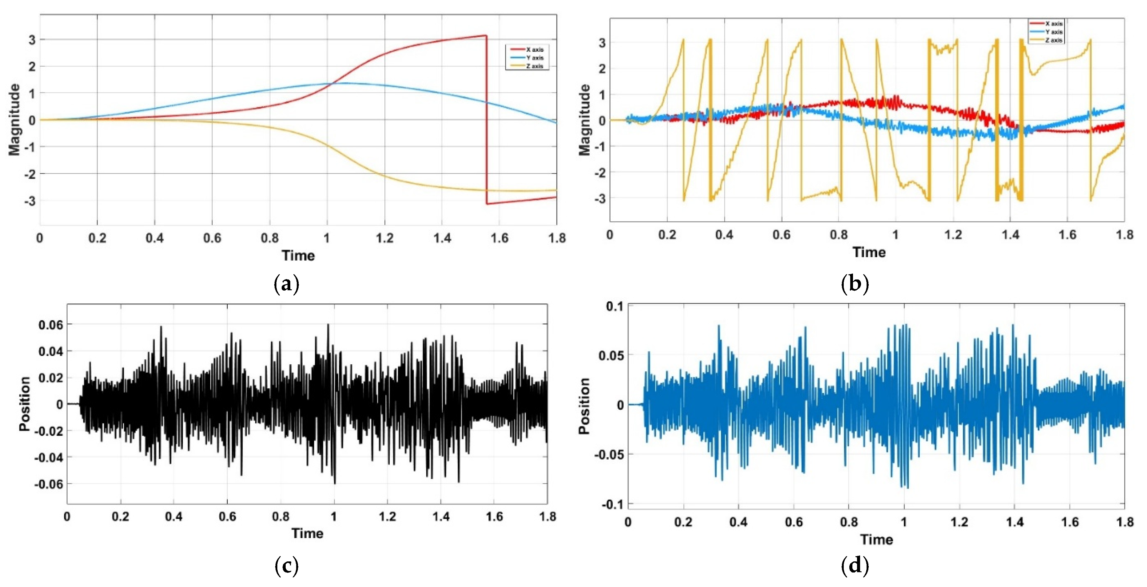
Figure 18.
Roll, Pitch and Yaw Response during Free-Fall from 25-meter Hight (a) without Shifting Device; (b) with Shifting Device Enabled, (c) is Position change for X axis during Free-Fall With Shifting Device from 25-meter Hight, and (d) is Position change for Y axis during Free-Fall With Shifting Device from 25 meters Hight.
Author Contributions
Conceptualization, Anas Ahmed. and Xu Jing.; methodology, Anas Ahmed; experiment, Anas Ahmed and Tong Guangjin; writing—original draft preparation, Anas Ahmed; writing—review and editing, Xu Jing.; supervision, Xu Jing; funding acquisition, Xu Jing. All authors have read and agreed to the published version of the manuscript.
Funding
This research was funded by NSFC, grant number 51205344.
Abbreviations
| Roll, pitch, yaw (Euler angles) | |
| Angular rates | |
| Body angular velocity components | |
| Position and velocity of UAV body origin | |
| Total mass of UAV (incl. CoM device) | |
| Principal moments of inertia | |
| Slider (payload) position in body frame | |
| In-plane displacements | |
| Slider velocities | |
| Shifting payload mass (battery) | |
| Rotor-generated body torques | |
| Gravity torque from CoM shift | |
| In-plane actuator forces at carriage | |
| Motor angle and angular speed | |
| Motor rotor inertia and viscous loss | |
| Inductance and resistance | |
| Torque constant, back-EMF constant | |
| Motor electromagnetic torque | |
| Load torque at motor shaft | |
| Current-limit relation (A4988 driver) | |
| Individual rotor thrusts | |
| Rotor propulsive coefficient | |
| Kinetic and potential energy | |
| Total mechanical energy | |
| State-space matrices (linearized model) | |
| Stage friction coefficients |
References
- Bouabdallah, S.; Murrieri, P.; Siegwart, R. Design and Control of an Indoor Micro Quadrotor. In Proceedings of the IEEE International Conference on Robotics and Automation, 2004. Proceedings. ICRA ’04. 2004; IEEE: New Orleans, LA, USA, 2004; pp. 4393-4398 Vol.5.
- Farajijalal, M.; Eslamiat, H.; Avineni, V.; Hettel, E.; Lindsay, C. Safety Systems for Emergency Landing of Civilian Unmanned Aerial Vehicles (UAVs)—A Comprehensive Review. Drones 2025, 9, 141. [CrossRef]
- Ahmad, F.; Bhandari, A.; Kumar, P.; Patil, P.P. Modeling and Mechanical Vibration Characteristics Analysis of a Quadcopter Propeller Using FEA. IOP Conf. Ser. Mater. Sci. Eng. 2019, 577, 012022. [CrossRef]
- Samadikhoshkho, Z.; Lipsett, M. Decoupled Control Design of Aerial Manipulation Systems for Vegetation Sampling Application. Drones 2023, 7, 110. [CrossRef]
- Gedefaw, E.A.; Abera, N.B.; Abdissa, C.M. A Review of Modeling and Control Techniques for Unmanned Aerial Vehicles. Eng. Rep. 2025, 7, e70215. [CrossRef]
- Qiu, X.; Gao, C.; Wang, K.; Jing, W. Attitude Control of a Moving Mass–Actuated UAV Based on Deep Reinforcement Learning. J. Aerosp. Eng. 2022, 35, 04021133. [CrossRef]
- Xu, L.; Qin, K.; Tang, F.; Shi, M.; Lin, B. A Novel Attitude Control Strategy for a Quadrotor Drone with Actuator Dynamics Based on a High-Order Sliding Mode Disturbance Observer. Drones 2024, 8, 131. [CrossRef]
- Haomiao Huang; Hoffmann, G.M.; Waslander, S.L.; Tomlin, C.J. Aerodynamics and Control of Autonomous Quadrotor Helicopters in Aggressive Maneuvering. In Proceedings of the 2009 IEEE International Conference on Robotics and Automation; IEEE: Kobe, May 2009; pp. 3277–3282.
- Alexander, R.M. Principles of Animal Locomotion; Princeton Paperbacks; Princeton University Press: Princeton, 2006; ISBN 978-0-691-12634-0.
- Mo, X.; Ge, W.; Miraglia, M.; Inglese, F.; Zhao, D.; Stefanini, C.; Romano, D. Jumping Locomotion Strategies: From Animals to Bioinspired Robots. Appl. Sci. 2020, 10, 8607. [CrossRef]
- Zakaryan, N.; Harutyunyan, M.; Sargsyan, Y. Bio-Inspired Conceptual Mechanical Design and Control of a New Human Upper Limb Exoskeleton. Robotics 2021, 10, 123. [CrossRef]
- Chovancová, A.; Fico, T.; Chovanec, Ľ.; Hubinsk, P. Mathematical Modelling and Parameter Identification of Quadrotor (a Survey). Procedia Eng. 2014, 96, 172–181. [CrossRef]
- Soe, M.T.; Munyaradzi Pepukai Antony Modeling and Control of a Quadcopter: A MATLAB-Based Simulation Framework. 2024. [CrossRef]
- Nguyen, N.; Hong, S. Fault-Tolerant Control of Quadcopter UAVs Using Robust Adaptive Sliding Mode Approach. Energies 2018, 12, 95. [CrossRef]
- Ivaldi, S.; Padois, V.; Nori, F. Tools for Dynamics Simulation of Robots: A Survey Based on User Feedback.
- Pounds, P.; Mahony, R.; Corke, P. Modelling and Control of a Quad-Rotor Robot.
- Emimi, M.; Khaleel, M.; Alkrash, A. The Current Opportunities and Challenges in Drone Technology.
- Lee, D.-J.; Jung, G.-P. A Miniature Jumping Robot Using Froghopper’s Direction-Changing Concept. Biomimetics 2025, 10, 264. [CrossRef]
- Sun, H.; Li, J.; Wang, R.; Yang, K. Attitude Control of the Quadrotor UAV with Mismatched Disturbances Based on the Fractional-Order Sliding Mode and Backstepping Control Subject to Actuator Faults. Fractal Fract. 2023, 7, 227. [CrossRef]
- Hehn, M.; D’Andrea, R. A Flying Inverted Pendulum. In Proceedings of the 2011 IEEE International Conference on Robotics and Automation; IEEE: Shanghai, China, May 2011; pp. 763–770.
- Zhou, Y.; Yan, L.; Han, Y.; Xie, H.; Zhao, Y. A Survey on the Key Technologies of UAV Motion Planning. Drones 2025, 9, 194. [CrossRef]
- Li, J.; Wan, L.; Li, J.; Hou, K. Adaptive Backstepping Control of Quadrotor UAVs with Output Constraints and Input Saturation. Appl. Sci. 2023, 13, 8710. [CrossRef]
- Jiang, Z.; Song, T.; Yang, B.; Song, G. Fault-Tolerant Control for Multi-UAV Exploration System via Reinforcement Learning Algorithm. Aerospace 2024, 11, 372. [CrossRef]
- Wiley, J. Mark W. Spong, Seth Hutchinson, and M. Vidyasagar.
- Falanga, D.; Zanchettin, A.; Simovic, A.; Delmerico, J.; Scaramuzza, D. Vision-Based Autonomous Quadrotor Landing on a Moving Platform. In Proceedings of the 2017 IEEE International Symposium on Safety, Security and Rescue Robotics (SSRR); IEEE: Shanghai, China, October 2017; pp. 200–207.
Figure 1.
(a) is Top view of the proposed -shifting mechanism integrated into the quadrotor frame. Components include: (1) Y-axis slider, (2) rack, (3) pinion gear, (4) Y-axis motor, (5) X-axis motor, and (6) X-axis slider, (b) is Mechanical assembly of the translational -shifting unit. The under-slung stage repositions the battery payload along orthogonal axes, providing additional control authority for quadrotor stabilization and attitude management and (c) is Exploded CAD rendering of the translational -shifting unit. The design illustrates the mechanical guidance system, including rail supports and gear-driven actuation, which allows independent displacement along the x- and y-axes.
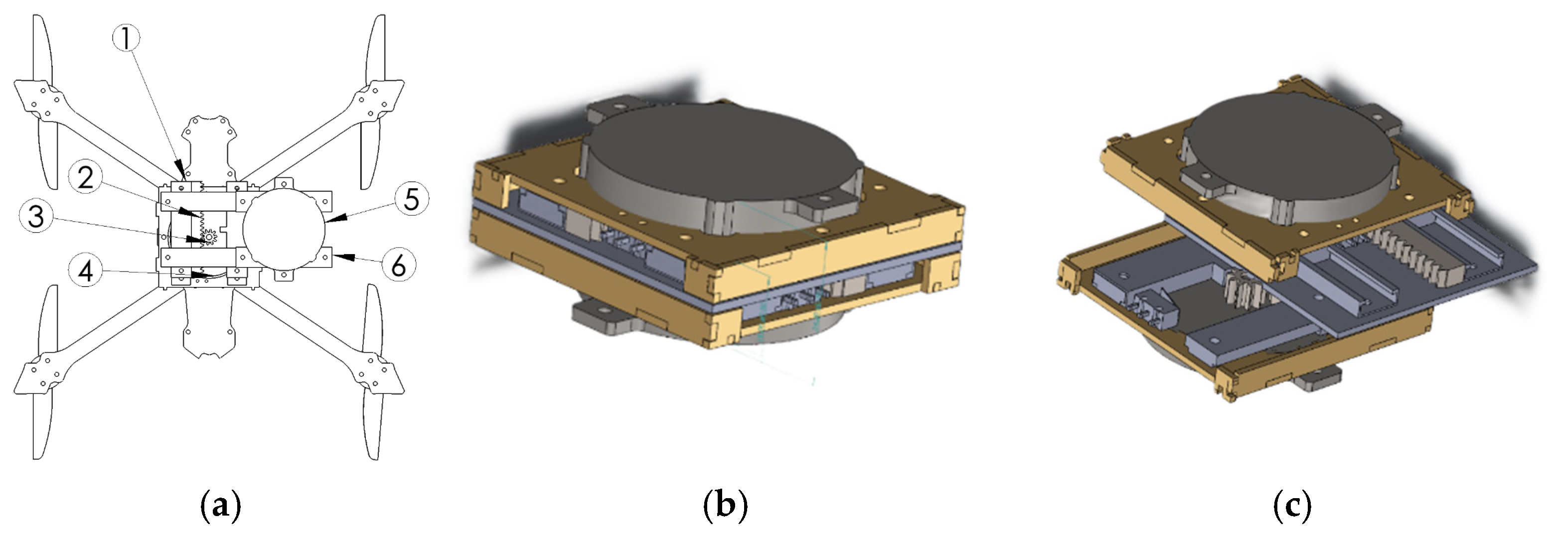
Figure 2.
Top view of the quadrotor equipped with the -shifting mechanism. The guiding frame (blue) constrains the motion of the shifting plate (cyan). The (green) marks the geometric center, while the CoM (magenta) indicates the shifted mass location. CW/CCW show rotor rotation directions.
Figure 2.
Top view of the quadrotor equipped with the -shifting mechanism. The guiding frame (blue) constrains the motion of the shifting plate (cyan). The (green) marks the geometric center, while the CoM (magenta) indicates the shifted mass location. CW/CCW show rotor rotation directions.
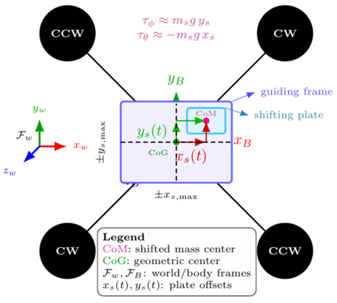
Figure 3.
Top view of the proposed -shifting mechanism integrated into the quadrotor frame. Components include: (1) Y-axis slider, (2) rack, (3) pinion gear, (4) Y-axis motor, (5) X-axis motor, and (6) X-axis slider. The system allows bi-directional payload displacement along X and Y axes for dynamic adjustment.
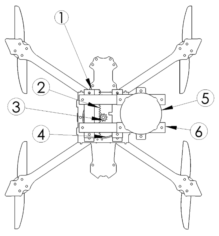
Figure 4.
System Architecture of the Drone Center-of-Mass Shifting Device.
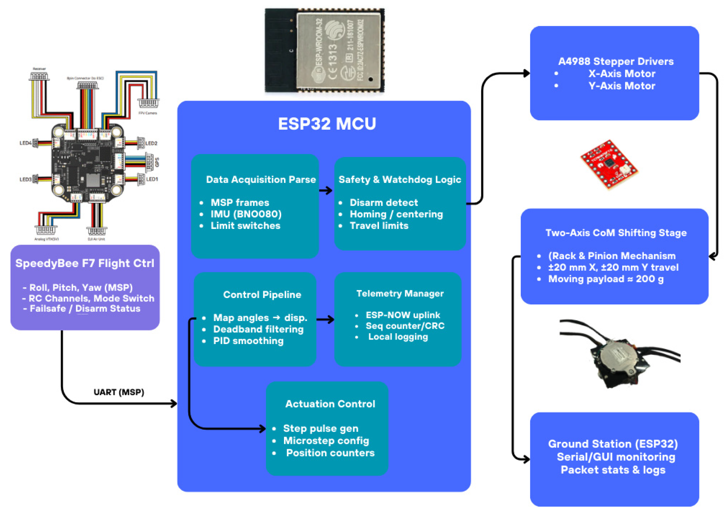
Figure 6.
Illustration of the center of mass in a two-body system. The distances and are inversely proportiona to the respective masses and .
Figure 6.
Illustration of the center of mass in a two-body system. The distances and are inversely proportiona to the respective masses and .
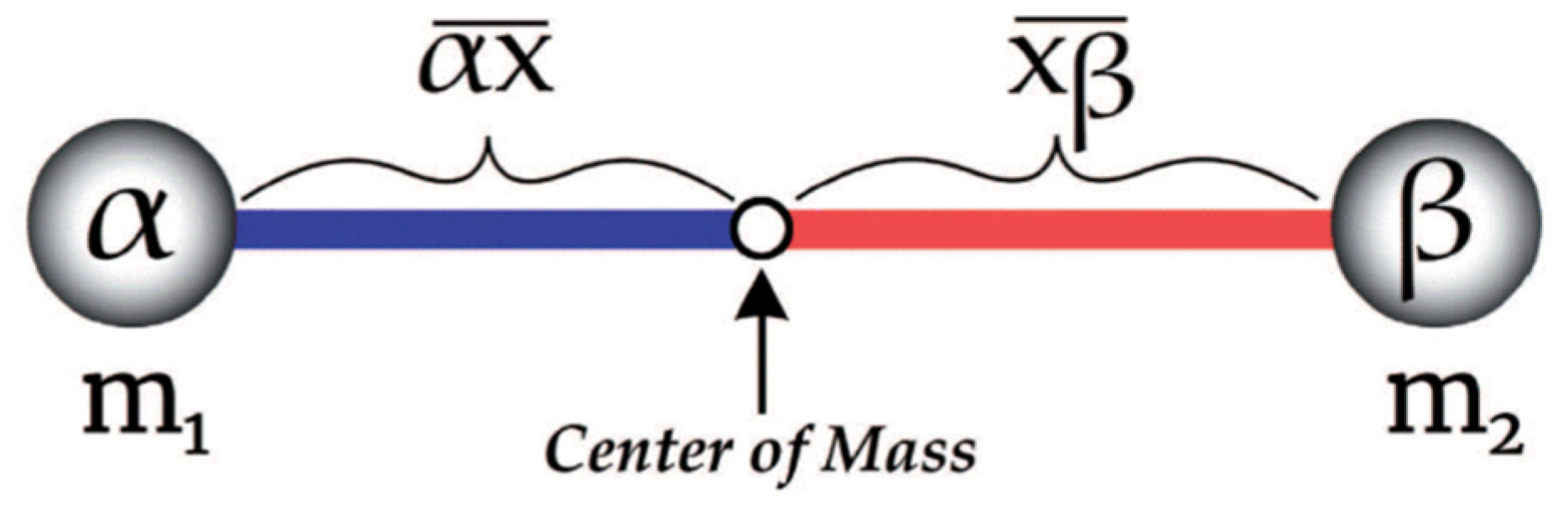
Figure 8.
Constrained Axis Drone Test Fixture for Validation of Shifting Device.
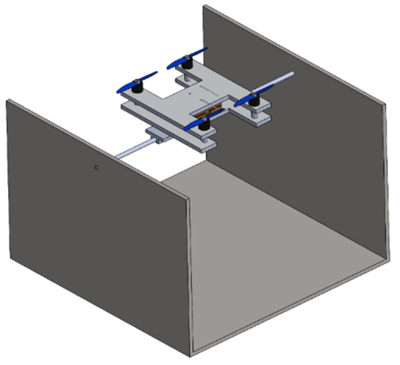
Figure 10.
Detailed Subsystem of the Simulink Model for Shifting Dynamics.
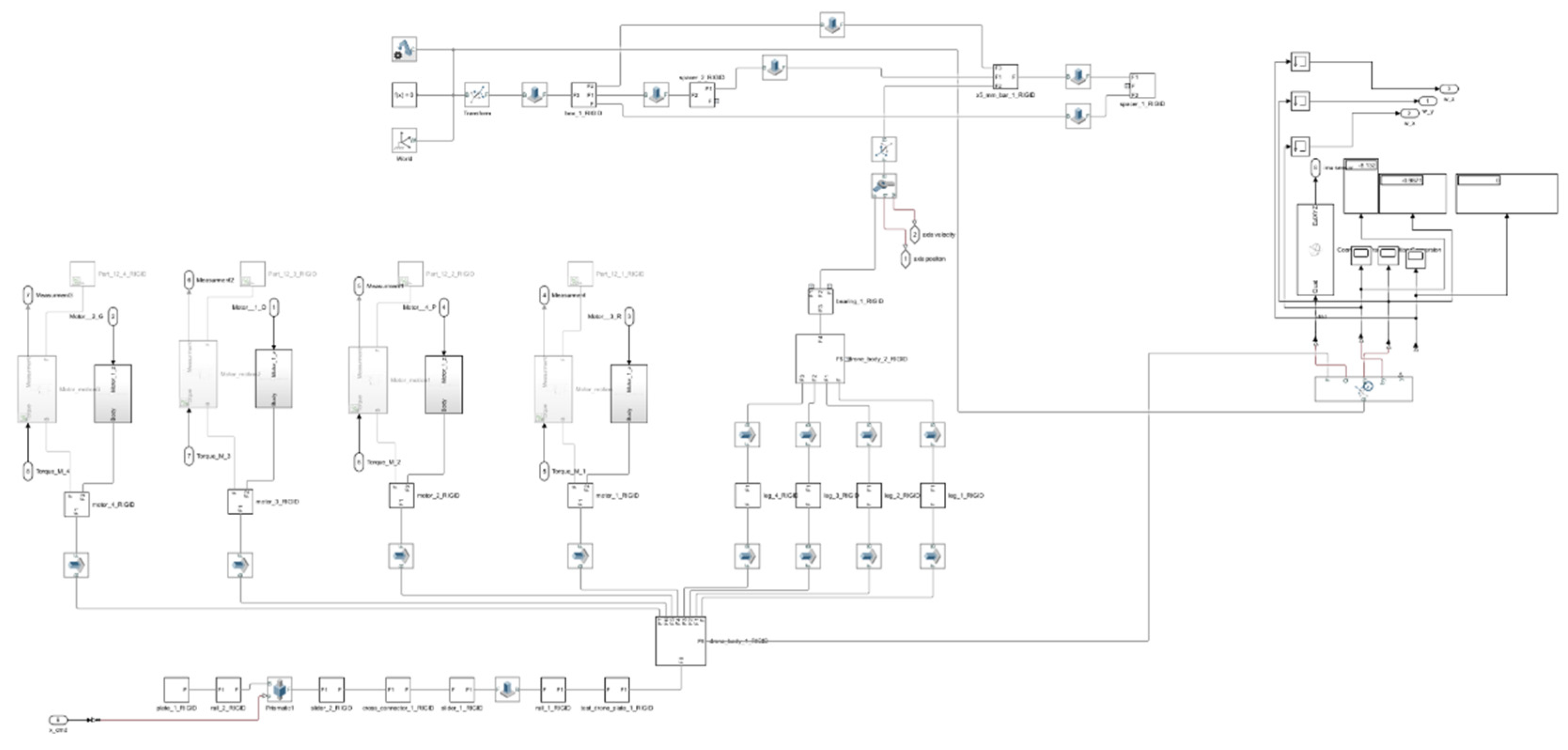
Figure 12.
Quadcopter Test Rig for Evaluating the Shifting Mechanism.

Figure 13.
RC Roll Input and Roll Angle Response with: (a) Shifting Device Disabled; (b) Shifting Device Enabled.
Figure 13.
RC Roll Input and Roll Angle Response with: (a) Shifting Device Disabled; (b) Shifting Device Enabled.
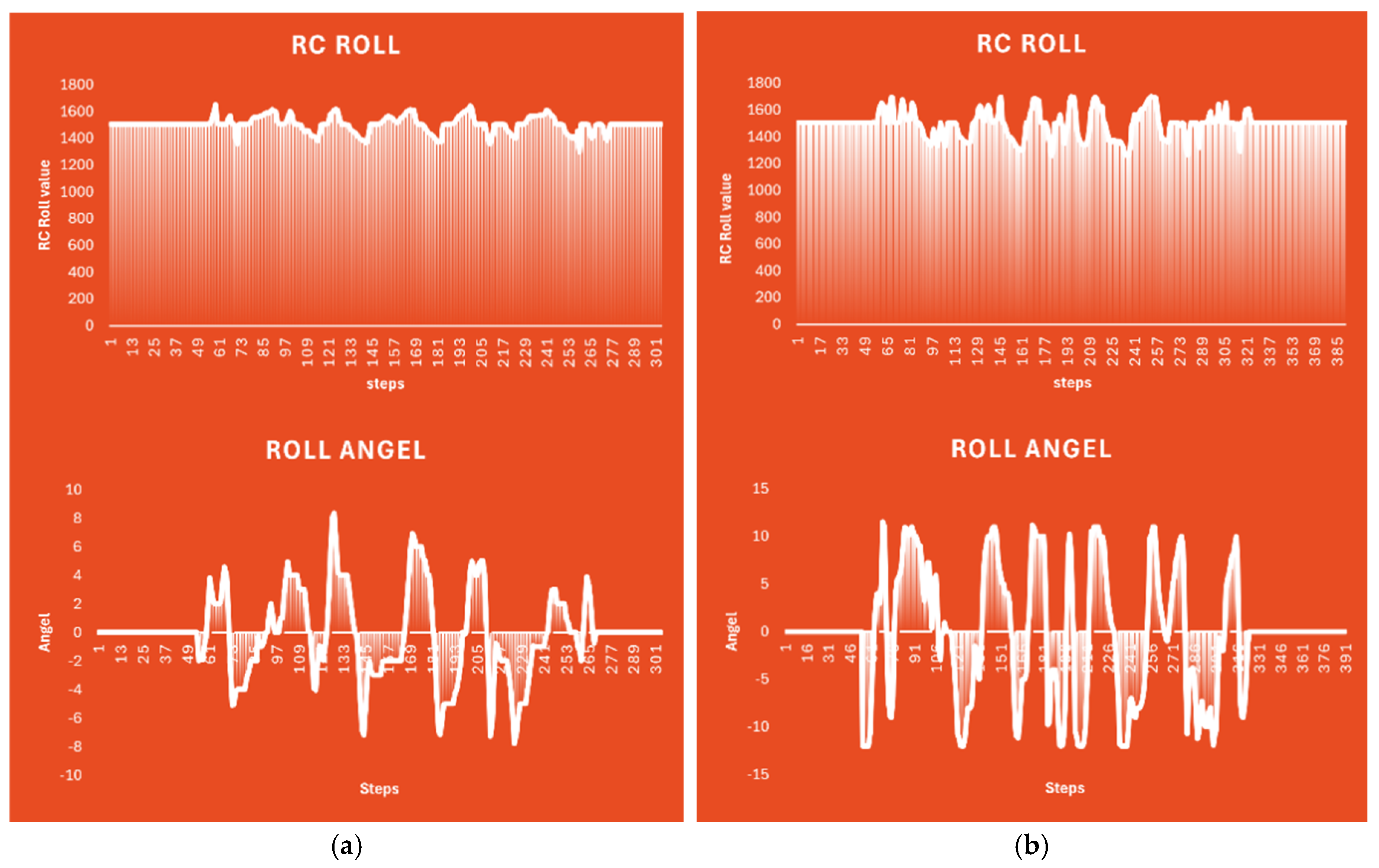
Figure 14.
Block Diagram Representation of the UAV Self-Righting Dynamics.
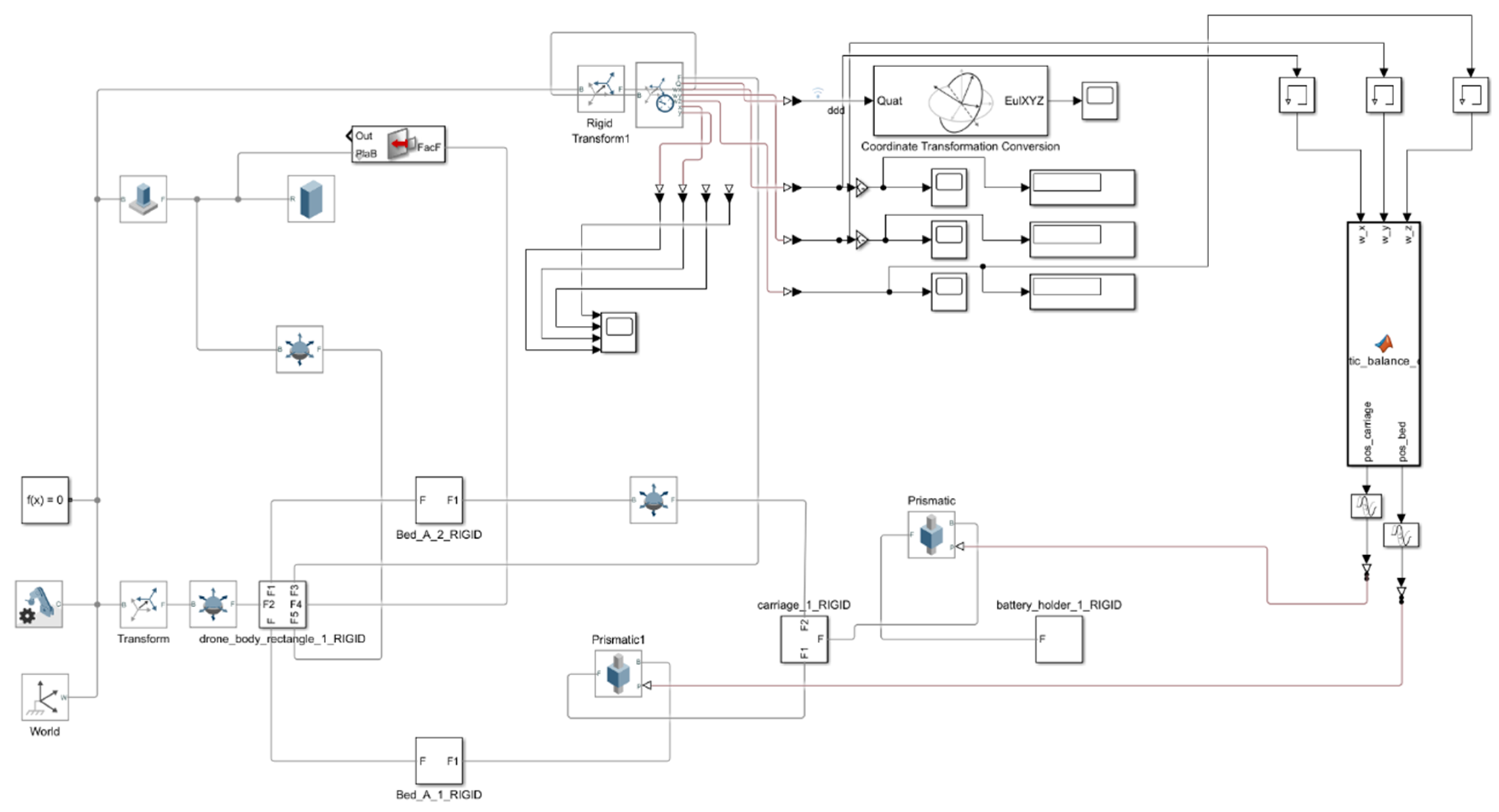
Figure 15.
Flowchart of the prismatic balance control algorithm showing initialization, PID calculation, saturation, filtering, and output.
Figure 15.
Flowchart of the prismatic balance control algorithm showing initialization, PID calculation, saturation, filtering, and output.
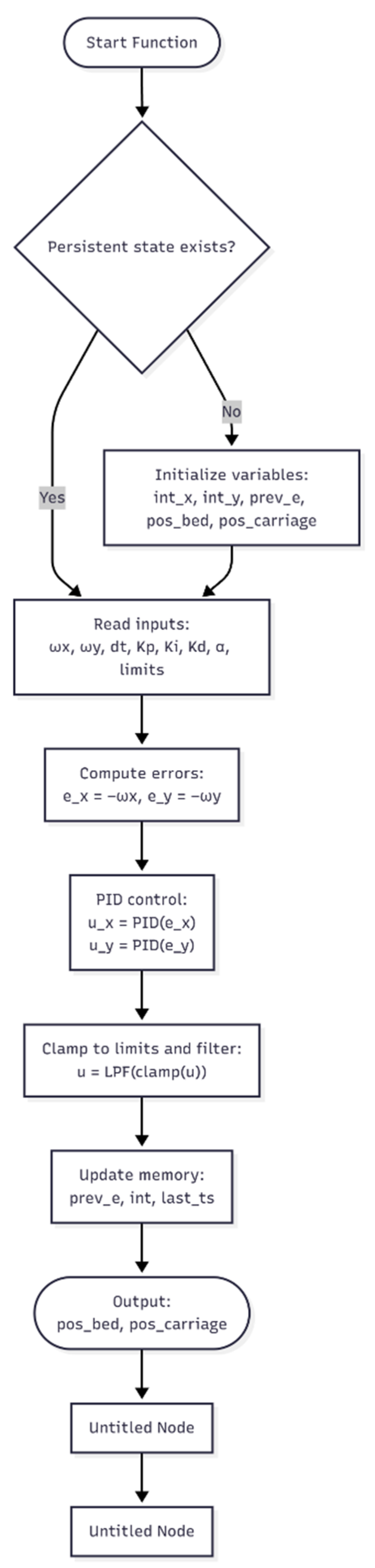
Figure 16.
Drone Free-Fall Behavior: (a) without Shifting Device (Upside-Down Impact); (b) with Shifting Device (Stable Horizontal Landing).
Figure 16.
Drone Free-Fall Behavior: (a) without Shifting Device (Upside-Down Impact); (b) with Shifting Device (Stable Horizontal Landing).
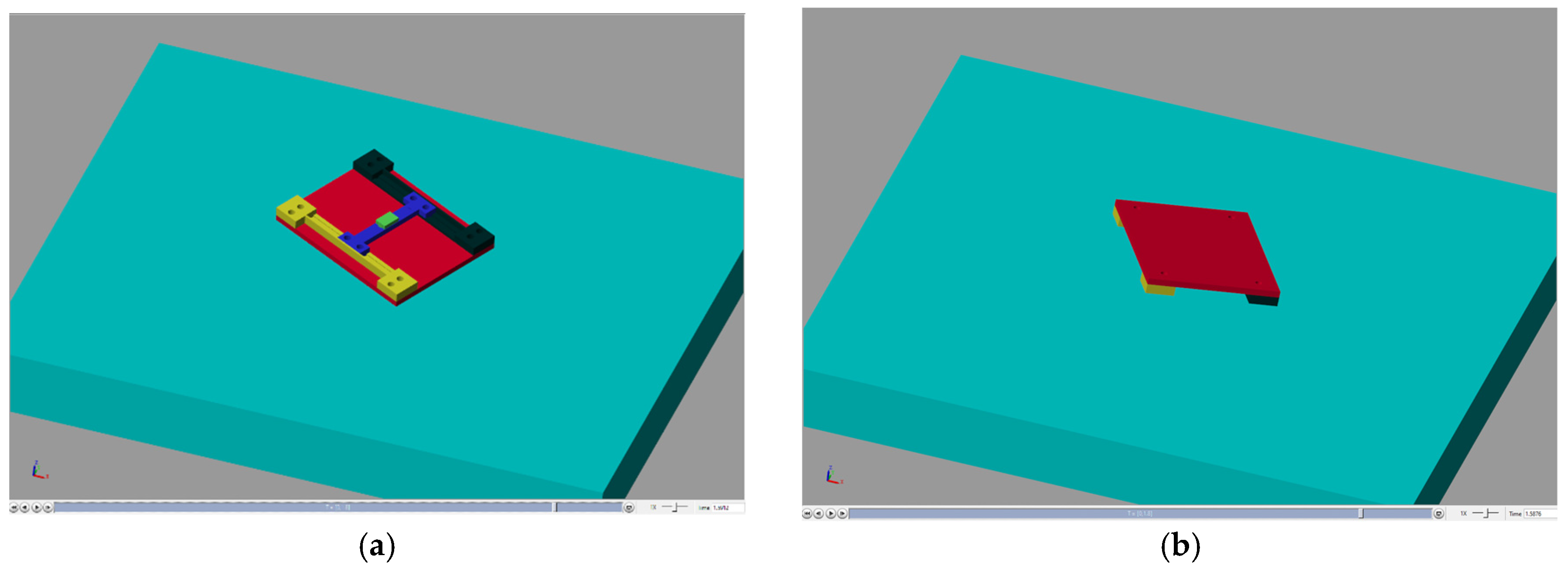
Figure 18.
Future UAV Concept with Magnetic Battery Bed (3D view). CAD rendering of the quadcopter frame showing the proposed magnetic linear actuator system integrated along the central fuselage, with the battery mounted on a movable bed.
Figure 18.
Future UAV Concept with Magnetic Battery Bed (3D view). CAD rendering of the quadcopter frame showing the proposed magnetic linear actuator system integrated along the central fuselage, with the battery mounted on a movable bed.
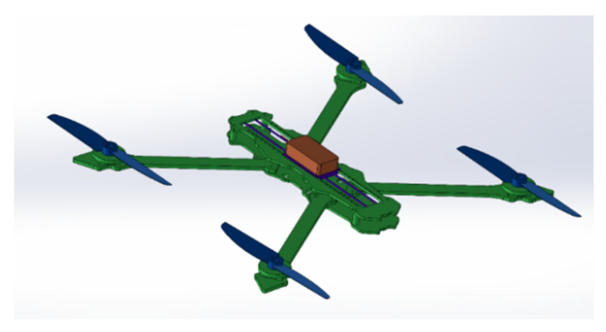

Table 1.
Experimental Results of Force, Torque, and Roll Angle for Different Masses.
| Payload Mass (g) | Maximum Force (N) | Maximum Torque (N·m) | Maximum Roll Angle (rad) |
| 50 | 3.1479 | 0.4174 | 0.90 |
| 100 | 5.1678 | 0.6940 | 1.20 |
| 200 | 9.1835 | 1.2375 | 1.35 |
Table 2.
Energy Consumption for Different Payloads.
| Payload Mass (g) | Power Consumption (W) | Time per Adjustment (s) | Energy Consumption (J) |
| 50 | 0.15 | 3 | 0.45 |
| 100 | 0.25 | 4 | 1.00 |
| 200 | 0.40 | 6 | 2.40 |
Table 3.
Comparison of Drone Free-Fall Stability with and without Shifting Device.
| Parameter | With COM Device Disable | Time per Adjustment (s) |
| Max roll deviation (°) | ~90° | < 5° |
| Max pitch deviation (°) | ~90° | < 5° |
| Final impact orientation | Inverted | Upright |
| Stability retention | < 10% | > 90% |
Disclaimer/Publisher’s Note: The statements, opinions and data contained in all publications are solely those of the individual author(s) and contributor(s) and not of MDPI and/or the editor(s). MDPI and/or the editor(s) disclaim responsibility for any injury to people or property resulting from any ideas, methods, instructions or products referred to in the content. |
© 2025 by the authors. Licensee MDPI, Basel, Switzerland. This article is an open access article distributed under the terms and conditions of the Creative Commons Attribution (CC BY) license (http://creativecommons.org/licenses/by/4.0/).
Copyright: This open access article is published under a Creative Commons CC BY 4.0 license, which permit the free download, distribution, and reuse, provided that the author and preprint are cited in any reuse.


