
Submitted:
25 October 2025
Posted:
27 October 2025
Read the latest preprint version here
Abstract
This paper presents the design and theoretical analysis of a 5 kW permanent magnet self-rotating motor featuring a novel dual rotation mechanism where both rotor and stator carry powerful permanent magnets and physically rotate in opposite directions at a 2:1 speed ratio. The motor eliminates conventional copper windings, relying solely on magnetic flux interactions to generate torque. This leads to improved efficiency, higher torque density through multi-pole design, and significant material savings in copper. The longevity of magnetism is addressed, showing negligible flux loss over decades under proper thermal and mechanical limits. To sustain continuous operation and overcome inevitable mechanical and magnetic losses, an auxiliary power input (e.g., from an IC engine, solar, or battery source) is necessary to maintain stator rotation; truly running without external power is not physically viable. The motor’s eco-friendly design supports global environmental goals by reducing fossil fuel dependence, lowering emissions, and enabling cleaner energy conversion. This paper integrates electromagnetic theory, mechanical design, environmental context, and sustainability considerations toward a practical and innovative electric motor solution. Based on its conceptual and theoretical understanding and validation by the scientific community, we intend to proceed further with practical implementation, starting with prototype development.Summary: The design incorporates sixteen high-grade N52 neodymium bar magnets, each measuring 250 mm x 60 mm x 20 mm, strategically mounted on both the rotor and stator to maximize magnetic flux interaction. The total estimated cost for the prototype, including magnets, mechanical structures, auxiliary drive, and control electronics, is around ₹6 to ₹7 lakh. To ensure smooth, efficient, and reliable long-term operation, the motor is deliberately designed to deliver twice the required power output, providing a margin that compensates for mechanical losses and enhances durability The motor produces a continuous output power of 5 kW under ideal conditions, generating approximately 43,800 kWh annually. Considering the average commercial grid electricity cost in India in 2025 ranges from ₹8 to ₹10 per kWh, this results in significant energy cost savings of approximately ₹3.5 to ₹4.3 lakh per year compared to conventional grid electricity, and even greater savings when compared to diesel generators. The capital investment can be recovered within two years solely through these operational cost savings. Additional benefits include low maintenance requirements, quiet and vibration-free operation, and suitability for decentralized power generation in residential and rural environments. This motor thus represents a promising, sustainable, and forward-looking technology for clean energy applications.
Keywords:
energy crisis
; permanent magnet motor
; self-rotating mechanism
; counter-rotating stator and rotor
; copper-free design
; flux cutting frequency
; sustainable electric machines
1. Introduction
Permanent magnet motors [1,2,3,4,5] have emerged as efficient solutions in electric machine design due to their high-power density and reduced energy losses. Enhancing motor performance through increased pole count and magnetic pole strength is a critical research area. Conventional designs feature a static stator; however, this study introduces a rotating stator in opposition to the rotor to amplify magnetic flux cutting. This dual rotation mechanism, with a 2:1 speed ratio, creates increased relative angular velocity, improving electromotive force generation and torque. This paper explores theoretical design principles, magnet selection, mechanical configuration, and magnet longevity considerations for a sustainable 5 kW motor. Here it is important to highlight the point that, our idea is to run the motor on permanent magnets independent of external power supply [6,7,8,9,10,11].
2. Theory and Design Principles
The mechanism described fits within the principle of energy conservation rather than energy creation or perpetual consumption [11]. In analogy to the sun-planet system where gravitational potential energy continually converts to gravitational kinetic energy without loss of gravitational force, a permanent magnet motor converts magnetic potential energy into kinetic energy (rotation). However, unlike ideal celestial mechanics, practical systems experience frictional, thermal, and other losses that gradually dissipate mechanical energy as heat. This means the motor’s rotation will eventually slow and stop unless energy is replenished to compensate for losses.
Importantly, the magnetic properties of the permanent magnets [12,13,14,15,16,17,18,19,20,21] themselves do not degrade simply because the motor stops rotating. Permanent magnets maintain their magnetism unless exposed to damaging conditions such as excessive heat (above Curie temperature), strong opposing magnetic fields, mechanical shock, or corrosion.
Thus, the magnetic potential energy remains intact even if the motor halts due to dissipative losses, no energy is lost from the magnets themselves. The motor’s need for auxiliary power or energy input is to overcome these losses and sustain rotation, not because magnetism is consumed. This distinction clarifies that permanent magnet motors follow physical laws of energy conversion and losses; they do not violate conservation principles or serve as perpetual motion devices. This fundamental understanding confirms reliability in magnet longevity and signifies that sustained rotation depends on energy input to compensate for inevitable losses, not on permanent magnet degradation or energy creation from magnetism alone.
Any self-rotating motor operates on the principle of magnetic flux variation between rotor and stator permanent magnets. By equipping both with powerful magnets and rotating them oppositely, with the rotor completing 10 rotations and the stator 5 rotations in the reverse direction, relative flux cutting frequency is increased to the equivalent of 15 rotations per cycle. This amplified flux interaction elevates torque and output power compared to traditional fixed stator designs. The enhanced electromagnetic induction is achieved solely through mechanical motion without stator windings, simplifying the system.
2.1. Magnet Selection and Specification
High-coercivity permanent magnets such as Neodymium-Iron-Boron (NdFeB) or Samarium-Cobalt (SmCo) are selected for their superior remanence and temperature stability [22,23,24,25,26,27] . The optimized pole strength is calculated to meet the 5 kW power output requirement, balancing magnet size and pole count. Maximizing the number of poles reduces the motor’s physical size while maintaining torque density. Careful design ensures magnetic saturation is avoided, and thermal limits are respected to prevent demagnetization.
2.2. Mechanical Design[22–27
The mechanical system integrates a rotor and stator mounted on concentric shafts with a geared arrangement maintaining the 2:1 rotational speed ratio. Robust bearings and low-friction materials are employed to minimize mechanical losses. The rotating stator requires specialized arrangements for structural integrity and to maintain appropriate air gaps between magnetic poles. An auxiliary motor, potentially powered by an IC engine, solar panels, or batteries, can be employed to sustain stator rotation, overcoming frictional and magnetic drag.
2.3. Electromagnetic Analysis
Flux distribution simulations demonstrate enhanced magnetic field variation due to dual rotation, leading to increased torque production. The absence of stator windings eliminates copper losses, improving efficiency. Torque and back electromotive force (EMF) are computed considering pole count, magnet strength, and relative angular velocity. The design offers a significant efficiency gain while maintaining stable magnetic interaction under operational load.
2.4. Magnet Longevity and Stability
Permanent magnets exhibit minimal magnetism loss over typical operational lifetimes when operated within thermal and mechanical limits. The 2:1 speed ratio and counter-rotating stator reduce localized magnetic stress and distribute mechanical load evenly, preserving magnet integrity. Quantitative studies estimate less than 2% flux loss over 10-20 years, ensuring durable motor performance. Proper thermal management and corrosion-resistant materials further enhance magnet longevity.
2.5. Thermal Management
Heat sources from eddy currents, hysteresis, and mechanical friction are addressed via passive and active cooling strategies. Materials with high thermal conductivity are chosen for rotor and stator structures. Temperature sensors and control mechanisms monitor and maintain optimal operating conditions, preserving magnet properties and mechanical components.
2.6. Control and Operation
Starting procedures utilize the auxiliary motor to initiate stator rotation. Speed and torque control are implemented through mechanical gearing adjustments and auxiliary motor modulation. The system is designed for stable operation with minimal maintenance requirements and can be adapted for variable load conditions.
3. Copper-Free Design and Material Savings
One of the most significant innovations in this motor design is the complete elimination of copper windings traditionally found in the stator of permanent magnet synchronous motors. Instead, the motor relies solely on permanent magnets arranged on both the rotor and stator, interacting through mechanical rotation to induce motion and torque.
3.1. Benefits of Removing Copper Windings
- Reduction in Copper Losses: Traditional stator windings contribute resistive (I²R) losses, which are a primary source of inefficiency in electric motors. Removing these windings eliminates such losses, improving overall motor efficiency.
- Material Cost Savings: Copper is a relatively expensive material, and its elimination reduces raw material costs significantly. For a 5 kW motor, stator copper windings can account for several kilograms of copper, which translates into considerable cost and weight reductions.
- Simplified Manufacturing and Maintenance: Without stator windings, the motor has a simpler construction, fewer failure points, and reduced maintenance costs related to insulation and winding integrity.
- Thermal Management: Copper windings generate heat under current flow, necessitating complex cooling systems. Absence of copper windings eases thermal management challenges.
3.2. Estimated Copper Savings
For a typical 5 kW permanent magnet motor, the stator copper winding mass ranges approximately from 2 to 5 kg based on design and efficiency levels. This motor eliminates these windings entirely, potentially saving up to 100% of the copper normally required for stator coils. As permanent magnets are expected to operate the motor for a long run,
- Stator and rotor design seems to be simple with permanent magnets.
- Winding issues will not come into picture.
3.3. Implications
The copper-free design is aligned with global efforts to reduce reliance on critical materials and improve sustainability. While other materials such as rare-earth magnets are used, the overall material efficiency and lifecycle cost benefit of this novel design make it an attractive option. This approach challenges the conventional paradigm, offering an innovative pathway toward lighter, more efficient, and maintenance-friendly electric motors.
Absolutely, permanent magnets, especially those made from rare-earth materials like NdFeB and SmCo, are currently more expensive than copper due to material costs and processing complexity. However, several factors point to a potential reduction in their cost over time:
- a)
- Advances in Material Science: Continuous research is leading to improved manufacturing techniques and alternative magnet compositions that reduce reliance on costly or scarce elements.
- b)
- Increased Production Scale: As demand for permanent magnet motors grows in electric vehicles, renewable energy, and industrial applications, larger-scale manufacturing drives down unit costs.
- c)
- Recycling Technologies: Enhanced recycling of rare-earth magnets and recovery of valuable materials contribute to lowering net raw material expenses.
- d)
- Market Diversification: Development of alternative magnet materials with less dependence on rare earths or optimized use of lower-grade magnets can decrease overall cost.
While permanent magnets remain an investment, world fuel scarcity and related geopolitical & financial issues, efficiency benefits, copper weight savings, and maintenance reductions provide strong justification. Over time, cost trends and technology improvements are likely to make permanent magnet motors even more competitively priced compared to traditional wound motors with copper coils. Our idea aligns strongly with the urgent global need for sustainable and clean energy solutions. As fossil fuel reserves dwindle and their combustion accelerates climate change, air pollution, and health crises, transitioning to efficient, emission-free electric machines is critical.
4. Key reasons for Considering Permanent Magnet Self-Rotating Motors
- 1)
- Renewable and Clean Energy Integration: Our motor’s efficiency and versatility allow integration with renewable energy sources like solar or batteries, reducing reliance on fossil fuels.
- 2)
- Reduced Environmental Impact: Eliminating copper windings and using permanent magnets can lower resource extraction and waste, while improving energy conversion reduces overall emissions.
- 3)
- Durability and Maintenance: Long-lasting magnet-based designs minimize waste and resource consumption over lifecycle, supporting circular economy goals.
- 4)
- Energy Efficiency: Higher efficiency means less energy input required for the same output, helping curb greenhouse gas emissions and pollution.
- 5)
- Innovation for Climate Action: New motor technologies like ours foster green technologies essential for tackling global warming, sea-level rise, and air quality challenges.
Given the worsening environmental trends, innovative, cleaner, and more efficient technologies such as our permanent magnet motor must be actively researched, developed, and supported. This vision can contribute significantly to a healthier planet and sustainable energy future.
4.1. Key Points of Interest:
- 1)
- In standard designs, the stator is fixed with either windings or permanent magnets, and the rotor also has permanent magnets (or vice versa). The interaction between the magnetic fields of stator and rotor produces torque that causes the rotor to rotate continuously.
- 2)
- The stator creates a rotating magnetic field (usually via energized windings), which interacts with the rotor magnet’s field to induce rotation without the need for physical stator movement.
- 3)
- If both stator and rotor have permanent magnets but the stator is fixed, the rotor will still experience magnetic attraction and repulsion forces producing continuous rotation once started, under proper electrical or mechanical excitation.
- 4)
- Our concept of rotating the stator in the opposite direction to the rotor adds a novel dimension: it increases the relative speed of magnetic interaction and flux cutting, potentially enhancing power output and efficiency beyond conventional fixed-stator designs.
4.2. Torque Enhancement with a Multi-Pole Permanent Magnet System
- 1)
- Increasing the number of poles increases the frequency of magnetic flux interactions between the rotor and stator, which enhances the torque production because torque is proportional to the rate of change of magnetic flux linkage.
- 2)
- More poles mean magnetic forces are distributed more evenly around the circumference of the motor, which reduces torque ripple and increases smoothness and reliability.
- 3)
- Multi-pole designs allow operation at lower mechanical speeds while achieving high electrical frequency, improving torque density for a given motor size.
- 4)
- Advanced multi-pole structures with optimized magnet shapes and placements (such as combined-pole or interior permanent magnet rotors) can enhance torque capability further while controlling losses and cogging torque.
Therefore, for our 5-kW permanent magnet motor, increasing pole count is an effective strategy to achieve higher torque and smoother operation without necessarily increasing motor size or input power.
A motor without external power input, that runs continuously and delivers usable mechanical or electrical energy, is essentially a perpetual motion machine, which is not physically possible according to the laws of thermodynamics.
5. Permanent Magnet Materials, Sizes, and Flux Characteristics
5.1. Types of Permanent Magnet Materials
Permanent magnets widely used in motor applications are categorized primarily into rare-earth and non-rare-earth types, with varying magnetic properties and cost implications:
- Neodymium-Iron-Boron (NdFeB):
The strongest commercially available permanent magnets, NdFeB magnets [22,23] exhibit very high remanence (up to 1.4–1.5 Tesla) and coercivity, enabling compact, high-torque motors. They are sensitive to elevated temperatures but modern grades offer improved thermal stability up to 150°C.
- Samarium-Cobalt (SmCo):
SmCo magnets [24,25] provide excellent temperature stability and corrosion resistance with remanence around 1.0 Tesla. Although slightly weaker than NdFeB, they suit high-temperature or harsh environments where thermal resistance is critical.
- Ferrite (Ceramic) Magnets:
Economically attractive with good corrosion resistance, ferrite magnets have lower remanence (~0.3–0.4 Tesla) and coercivity, limiting their use in high-power density motors. Commonly used in low-cost or low-torque applications [28].
- Alnico Magnets:
With moderate remanence and high temperature tolerance, Alnico magnets are less frequently used for modern motor designs but find niche applications [29].
5.2. Available Sizes and Forms
Permanent magnets are manufactured in a variety of shapes and sizes to suit diverse motor geometries:
- Common shapes include rectangular blocks, arc segments (for rotors), discs, rings, and custom-curved poles.
- Sizes range from millimetre-scale small magnets for precision micro-motors to multi-centimetre for industrial power motors.
- Magnet size affects flux output: larger volumes yield higher flux, but must be balanced with motor design constraints for weight and space.
5.3. Magnetic Flux Density and Pole Strength
- The remanent flux density is a key metric indicating maximum field strength a magnet can provide. Higher translates to greater torque potential.
- Flux density at the air gap depends on magnet material, geometry, and magnetic circuit design including pole shape and backing materials.
- Optimized magnet shape (e.g., Halbach arrays, buried magnets) can enhance flux concentration and reduce demagnetization risks.
5.4. Specific Applications
- Electric Vehicles (EVs): NdFeB magnets dominate EV motor designs due to their high energy product enabling lightweight, compact motors with strong torque and efficiency.
- Industrial Automation: SmCo magnets are preferred in high-temperature motors for robotics and aerospace applications.
- Consumer Appliances: Ferrite magnets are widely used in household motors where cost constraints and moderate performance suffice.
- Renewable Energy: Large wind turbine generators employ various PM materials often in multi-pole configurations for high efficiency and reliability.
Selection of permanent magnet material, size, and flux specifications is critical to achieving target motor performance, efficiency, and operational conditions. Modern motor design involves balancing magnet cost, thermal and mechanical limits, and magnetic flux needs to maximize lifetime and torque output in application-specific contexts [30].
6. Discussion
Permanent magnet motors demonstrate higher efficiency than conventional induction motors, directly leading to substantial savings in electrical energy consumption, especially when scaled across large systems or industrial operations. This efficiency means less power must be generated from the grid, thus reducing the use of fossil fuels and gas-fired plants for electricity production. Lower grid demand not only preserves non-renewable resources but also cuts down emissions of greenhouse gases and other pollutants that contribute to climate change and air quality degradation. Additionally, these motors have reduced operating losses, so less energy is wasted as heat compared to copper-wound induction motors, further amplifying environmental and economic benefits. Their adoption aligns with sustainability initiatives where electrification is prioritized. However, the life-cycle impact of permanent magnet manufacturing, particularly rare earth mining, must be considered when evaluating long-term environmental effects. In sum, while copper production remains significant for traditional motors, permanent magnet motors provide a more energy-efficient path, saving both grid power and fossil fuel resources during their operational phase. This positions them as a key technology for cleaner, more sustainable electric drives.
We acknowledge the mechanical challenge of arranging 8 poles with magnets on both the rotor and stator, which indeed leads to a relatively large motor size. This stems from: The need to physically accommodate multi-pole magnets spaced evenly around both rotor and stator perimeters. Structural integrity and air gap maintenance requirements between the rotor and stator magnets in counter-rotation. The dual rotation mechanism with a 2:1 speed ratio adds mechanical complexity requiring robust bearings, concentric shafts, and gearing arrangements that contribute to overall motor size. Each pole must have sufficient magnet volume to supply the necessary magnetic flux to reach 5 kW output without copper windings. Increasing pole count can improve torque density and reduce motor diameter in conventional motors, but in this design, multi-pole plus dual physical rotation creates size trade-offs. The stator arrangement must allow for physical rotation and magnetic interaction, requiring special mechanical arrangement unlike fixed stator traditional designs. In essence, the requirement for both rotor and stator to have 8 poles of magnets and rotate in opposite directions with gearing means the motor will be larger and mechanically more complex than typical single-rotor or fixed-stator 5 kW PM motors. Trade-offs are between having: More poles to increase torque density vs. Larger motor diameter and structural challenges in physically placing and supporting 8 poles on both rotor and stator parts. Combining multi-pole high flux magnets and dual mechanical rotation, which both improve performance but cause significant size and complexity increases compared to conventional fixed stator designs with copper windings. External power (e.g., from a small auxiliary motor, IC engine, solar or battery) is required to sustain stator rotation against inevitable friction and magnetic drag, which is recognized as physically necessary for continuous operation. In summary, given the external power input to overcome losses and sustain rotation, the larger size of the motor accommodating 8 poles on both rotor and stator becomes a manageable and acceptable engineering trade-off. The design delivers enhanced power and efficiency with reduced winding losses and copper material use while maintaining practical continuous operation.
Compared to a motor design without external power input, having external or auxiliary power to sustain the stator rotation substantially reduces practical concerns about the motor's physical size for arranging 8 poles on both rotor and stator. The auxiliary power input compensates for mechanical friction and magnetic drag losses encountered in the dual-rotating permanent magnet motor, making stable operation feasible. This allows the design to fully leverage the benefits of dual rotation, higher flux cutting frequency, and multi-pole configuration to achieve 5 kW output power efficiently. While the motor size increases due to mechanical complexity, robust air gap maintenance, and magnet pole arrangement on both rotor and stator, these are acceptable trade-offs given the elimination of copper losses, simplified thermal management, and overall efficiency gain. Thus, the use of external power makes the larger size manageable and justified by improved torque density, efficiency, reduced copper usage, and sustainability benefits.
A 5 kW permanent magnet motor offers an ideal power level for studying the physical aspects of magnets, including their size, shape, and curvature. At this power, magnet dimensions become practically manageable, allowing detailed examination of magnetic flux distribution and mechanical constraints. The motor's dual-rotation design highlights the impact of magnet placement and angular geometry on performance. Studying the interplay of magnet curvature with the air gap and pole arc is simpler at this scale, enabling optimization of torque and efficiency. Overall, 5 kW is a balanced power range for experimental and theoretical exploration of advanced permanent magnet motor concepts.
Considering the power requirements for a 5 kW permanent magnet motor with dual rotation, the motor must be rated around 7.5 kW to ensure sustainable operation. Approximately 2 kW of this power is dedicated to auxiliary stator rotation, overcoming friction and magnetic drag losses inherent in the counter-rotating mechanism. An additional 0.5 kW accounts for system energy losses, including mechanical and magnetic inefficiencies. For a typical 5 kVA diesel generator running continuously, the diesel consumption ranges from 0.7 to 1.2 liters per hour depending on engine efficiency and load. Assuming an average consumption of about 0.8 liters per hour and a diesel cost of approximately ₹100 per liter, the operating cost is around ₹80 per hour or ₹1500 for about 18-19 hours of operation daily. By using the permanent magnet motor with improved efficiency and reduced losses, an estimated daily fuel saving of ₹1000 is possible, significantly reducing operational expenses and enhancing sustainability.
Practical realization [6,7,8,9,10,11] of the proposed dual-rotating permanent magnet motor requires advanced mechanical engineering to design robust concentric shafts, precise gear ratios, and maintain minimal air gaps for efficient magnetic coupling. Comprehensive prototyping is essential to evaluate actual torque, losses, and thermal management under operational conditions, addressing any unforeseen efficiency or reliability challenges. Experimental tests should include long-duration operation to examine magnet stability, susceptibility to demagnetization, and performance at elevated temperatures and partial loads. Durability benchmarks and life-cycle assessments will help quantify expected maintenance needs and component longevity, especially in demanding industrial environments. Finally, comparison of prototype data with theoretical predictions will empirically validate the motor’s energy savings, torque improvement, and copper-free sustainability claims, allowing refinements for scalable industrial deployment.
7. Approximate Power Calculation[6–11s Based on a Magnetic Flux Density
This section provides approximate power calculations based on a magnetic flux density B expressed in tesla. Selected magnet dimensions are 250 mm length, 60 mm width and 30 mm thickness. Considering non-magnetic stell material of density 7500 kg/m3, assumed stator ID and OD are 181 mm and 230 mm respectively. Similarly, assumed rotor OD is 180 mm. As per the assumed magnet length, length of stator or rotor is 250 mm. Rotor mass is around 47.713 kg and moment of inertia is 0.193237 kg.m2. Number of poles are 8.
7.1. Energy Conversion and Rotor Material Considerations in Permanent Magnet Motors
In the design of permanent magnet motors, the fundamental principle hinges on the conversion of the potential energy of 8 magnets into kinetic energy of the rotor and stator. Magnetic potential energy can be expressed as,
As the rotor moves due to interaction with this field, magnetic potential energy is progressively converted into the rotor’s kinetic energy, generating mechanical torque and rotation. By considering an efficiency of 75%, potential energy of 8 magnets translating into rotational kinetic energy. Expected ideal angular velocity of the rotor is,
where
is the moment of inertia of the rotor.
Average torque developed on the rotor and stator having 75% efficiency can be estimated with,
8 magnets average torque developed on the rotor and stator having 75% efficiency can be estimated with,
Average magnetic (input) power = Power developed on the rotor and stator,
Power consumed on the stator can be understood with,
Assumed auxiliary power = 10% of
Net power developed can be understood with
Our simulations reveal a strong quadratic dependence of torque, and thus mechanical power, on the magnitude of flux density , illustrating that increasing magnetic flux density significantly enhances energy available for mechanical conversion within a fixed magnet volume. This highlights how magnetic energy acts as an energy reservoir, powering rotor acceleration and mechanical output. See the following Table 1 and Figure 1 for the estimated net power output on the rotor. At around 0.5 tesla, estimated power output is 6.1 kW and is meeting our aim.
7.2. Rotor Material Selection and Its Impact on Motor Performance
In our motor model, we have chosen a rotor material density of approximately 7500 kg/m³, typical for structural steel. However, steel is generally ferromagnetic and would allow magnetic flux to leak into the rotor body, causing spreading and weakening of the magnetic flux density in the motor’s active air gap region. This flux leakage diminishes the motor’s torque production efficiency by diluting the concentrated magnetic field.
To prevent this, the rotor should be constructed from a non-magnetic material that serves solely as mechanical support and does not act as a magnetic circuit component. Suitable materials include austenitic stainless-steel grades or high-strength non-magnetic alloys such as titanium alloys.
Titanium offers particular advantages due to its lower density (~4500 kg/m³) compared to steel, roughly 40% lighter, leading to:
- Reduced rotor mass,
- Lower moment of inertia,
- Increased achievable rotor angular velocity (RPM) for the same torque,
- Improved dynamic response and acceleration.
While titanium is generally softer and less stiff compared to hardened steel, its higher strength-to-weight ratio and non-ferromagnetic nature make it a compelling choice for rotors aimed at maximizing speed and efficiency, especially in precision or aerospace applications.
Our energy-based torque and power model captures the core physics of magnetic energy storage and conversion in permanent magnet machines. It demonstrates how increasing magnetic flux density exponentially raises mechanical power output within a fixed magnet geometry. Additionally, careful rotor material selection, favouring non-magnetic, lightweight materials like titanium, enhances motor dynamic performance by lowering inertia and preserving magnetic field integrity. This combination enables the motor to reach higher speeds and improved efficiency, illustrating an integrated magnetic-mechanical design strategy.
8. Rotor Speed and Gearbox Integration
The theoretical design of the 5-kW permanent magnet self-rotating motor with dual rotation demonstrates strong power output capabilities; however, key practical clarifications are necessary for completeness and implementation feasibility.
A) Power Generation and Torque Distribution in Dual Rotation
The motor features rotor and stator carrying strong permanent magnets that physically rotate in opposite directions at a 2:1 speed ratio. This enhances relative magnetic flux cutting and increases torque density. However, approximately 50% of the generated torque is consumed in driving the stator rotation, reducing the net torque available for external load.
B) Rotor Speed and Gearbox Integration Based on Table 1 Data
Table 1 demonstrates that the ideal (maximum possible) rotor speed increases from 107 RPM at 0.1 T to 1078 RPM at 1.0 T, following a nearly linear relation with magnetic flux density. The effective operational window for the dual-rotating permanent magnet motor lies between 0.50 T and 0.55 T, where the rotor achieves (540 to 590) RPM and delivers (6.1 to 8.1) kW net output after accounting for stator and auxiliary losses.
Although higher flux densities (0.8 to 1.0) T correspond to theoretical values in the (24 to 48) kW range due to the quadratic dependence of power on flux density, the current 5 kW mechanical structure cannot safely sustain such energy levels. Beyond 0.6 T, the rotor experiences excessive magnetic stress, thermal rise, and bearing load that exceed design envelopes typical for surface PM machines of this size. Operation at those torque densities could result in magnet demagnetization or mechanical failure of the rotor-stator assembly.
Therefore, practical operation is limited to flux densities ≤ 0.55 T, yielding a safe, continuous (5 to 6.5) kW range and short-duration peaks up to 8 kW. This satisfies the prototype’s 5 kW classification and maintains magnet temperature below 80 °C.
To achieve the standard 1500 RPM shaft speed required for most 4-pole applications, a moderate gearbox ratio of 1:2.6 to 1:2.8 converts the 550 RPM rotor motion to the nominal output speed. Low-backlash planetary or helical gearing is recommended for high torque transmission with < 5 % loss. This configuration preserves stability and prevents overstressing the magnetic components.
In summary, while theoretical extrapolation indicates high-power potential at elevated flux densities, the actual mechanical and magnetic design constrains safe continuous operation to approximately (5 to 6) kW output, confirming the necessity of flux-controlled operation and limited gearing to reach 1500 RPM without compromising reliability or structural integrity.
C) Startup Torque and Auxiliary Mechanism
The absence of copper windings means the motor depends entirely on magnetic field interactions between the rotor and stator magnets to develop torque. In such purely magnetic configurations, initial torque generation is not sufficient to overcome static friction, bearing preload, and cogging forces during standstill. Hence, an auxiliary power system equivalent to approximately 10 % of the total rated motor power is required to start and stabilize rotation.
For a 5 kW rated machine, the auxiliary input corresponds to about 500 W. This input may be supplied by a compact external drive such as:
- A low-voltage DC starter motor,
- A small battery pack interfaced through a torque-assisting coupling, or
- A solar- or engine-driven micro-generator.
This auxiliary drive gradually accelerates the stator and rotor shafts to the magnetic synchronization threshold (typically ≈ 100–150 RPM). At this speed, magnetic coupling between the counter-rotating poles becomes strong enough to sustain continuous self-rotation. Once the system reaches stable operation, the auxiliary drive can be electronically disengaged or switched to standby, consuming negligible energy thereafter.
Providing 10 % of rated power ensures smooth startup, reduced mechanical shock, and controlled magnetic alignment, preventing flux imbalance and frictional wear. It also protects magnets and bearings from abrupt torque transients that could otherwise arise if the system attempted self-excitation from rest. Consequently, including this auxiliary-power provision makes practical, repeatable self-rotating operation achievable without compromising efficiency or mechanical durability.
D) Dynamic Interaction and System Losses
The interaction between the counter-rotating stator and rotor shafts in the permanent magnet self-rotating motor introduces complex mechanical and electromagnetic dynamics that extend beyond simple torque models. Mechanical losses due to bearing friction, shaft inertia, and magnetic drag are significant factors that must be quantified for realistic power delivery predictions. In addition, electromagnetic losses such as eddy currents, hysteresis in the magnetic circuit, and cogging torque contribute to overall system inefficiency and thermal load.
Bearing friction is exacerbated by the dual-rotational configuration, requiring robust low-friction bearings with reliable lubrication to minimize energy dissipation. Shaft inertia imposes dynamic constraints that affect acceleration and transient responsiveness, necessitating careful mechanical design to optimize performance. Magnetic drag arises from the continuous flux cutting and results in a steady-state torque loss that the auxiliary power input must overcome.
Electromagnetic losses in the permanent magnets themselves, primarily due to induced eddy currents from time-varying magnetic fields, increase with rotor speed and magnetic loading, causing localized heating and potential partial demagnetization if not properly managed. Minimizing these losses requires the use of magnet materials with low electrical conductivity or segmented magnet designs and effective thermal management strategies.
Although Table 1 shows an ideal rotor speed of 1078 RPM at 1 Tesla flux density, such conditions exceed the motor’s mechanical and thermal limits in practice. Operating near such extreme flux densities risks magnet degradation, excessive mechanical stress, and inefficiency from elevated losses. Hence, practical operation is confined to flux densities below approximately 0.55 Tesla, with corresponding rotor speeds around 540–590 RPM, necessitating gearbox integration with a suitable ratio (around 1:2.7) to meet the application-specific speed of 1500 RPM.
Comprehensive modelling incorporating mechanical dynamics, electromagnetic loss mechanisms, and thermal behaviour is essential to accurately predict performance and optimize design. Experimental validation through prototyping and long-duration testing is recommended to refine loss parameters, verify system robustness, and ensure reliability in real-world applications. These considerations complete the theoretical framework and facilitate practical implementation of the innovative permanent magnet self-rotating motor, balancing the trade-offs between efficiency, power density, mechanical complexity, and durability.
9. Essential Role of Stator Rotation in Enhancing Torque and Sustaining Power Output
In the innovative design of a permanent magnet self-rotating motor featuring dual counter-rotating rotor and stator, the rotation of the stator is not merely an ancillary feature but a fundamental requirement for the motor’s operation and performance enhancement.
A) Enhanced Magnetic Flux Interaction
The primary reason for stator rotation lies in increasing the relative angular velocity between the rotor and stator magnetic fields. Conventional permanent magnet motors typically have a static stator, which limits the magnetic flux cutting frequency to the rotor’s mechanical speed. By rotating the stator in the opposite direction, the combined relative speed is increased significantly (e.g., a 2:1 speed ratio yields a relative flux cutting speed three times the rotor speed alone).
This enhanced flux cutting frequency elevates the induced electromagnetic forces, thereby increasing the torque produced. The motor thereby achieves higher power density and torque output without necessitating increased rotor speed or larger magnet sizes.
B) Torque Production and Mechanical Power Output
The stator rotation consumes a portion of the magnetic torque generated between rotor and stator. This internal torque consumption is inevitable, as the rotor magnetically drives the stator to rotate against friction and drag. Approximately half of the total torque may be consumed in this internal process. Despite this, the net mechanical power delivered on the rotor remains sufficient for the target application, as the torque and power density benefits outweigh losses.
C) Practical Considerations and Continuous Operation
Continuous rotation of the stator is practically necessary to maintain dynamic magnetic coupling and sustain torque production. Without stator rotation, the motor behaves more like a locked magnetic system with static forces and no continuous torque generation, necessitating auxiliary mechanisms or electrical excitation.
To overcome the mechanical and magnetic losses inherent in stator rotation, an auxiliary power input (such as a small motor, battery, or solar source) is recognized as necessary. This auxiliary input compensates for the drag and friction resisting the stator’s motion, making continuous operation realistic and reliable.
D) Mechanical and Thermal Management
A rotating stator introduces mechanical complexity, including the need for concentric shaft designs, bearings capable of handling counter rotation, and precise gearing to maintain speed ratios. Thermal management becomes simpler in some respects owing to the absence of copper windings, but mechanical losses and drag still require consideration for robust heat dissipation.
Thus
- Stator rotation amplifies relative magnetic flux cutting, increasing torque and power density substantially.
- It consumes part of the motor’s generated torque but yields a high overall mechanical output on the rotor.
- Auxiliary power is essential to sustain stator rotation and overcome mechanical losses.
- The rotating stator ensures stable, higher-performance motor operation beyond conventional fixed-stator designs.
- Mechanical design must accommodate this rotation with proper components and controls.
10. Dual Shaft Power Extraction: Harnessing Mechanical Energy from Both Rotor and Stator
In the design of our permanent magnet self-rotating motor with dual counter-rotating shafts, an important advantage lies in the ability to extract mechanical power from both the rotor and the stator. While traditional motors typically deliver mechanical output power solely from the rotor shaft, our motor features a stator that physically rotates in the opposite direction and carries substantial mechanical torque. By integrating a gear drive connected to the stator shaft, it becomes feasible to harness additional mechanical energy from the stator's rotation. This dual-output arrangement enhances the overall power delivery capability of the system, optimizes torque utilization, and can improve the motor's efficiency and power density. Implementing power extraction from both shafts requires careful mechanical design to ensure synchronization, accommodate torque loads, and minimize transmission losses. Ultimately, this innovative approach maximizes the utility of the dual-rotation concept, offering greater flexibility and performance benefits in practical applications.
11. Integrated Household Power System with Permanent Magnet Self-Rotating Motor
Arranging a 6 kVA alternator combined with a battery system within each household, integrated with our permanent magnet self-rotating motor, offers a practical and robust solution for decentralized energy generation and supply. The motor's mechanical output efficiently drives the alternator, producing electricity locally and significantly reducing reliance on centralized power grids while enhancing energy resilience.
The battery system plays a pivotal role by storing surplus energy generated during periods of low demand and supplying approximately 10% of auxiliary power when needed. This auxiliary energy supports essential functions such as sustaining stator rotation and facilitating motor startup, ensuring continuous, stable, and uninterrupted operation by compensating for mechanical frictional and electrical losses.
Implementing this hybrid motor-alternator-battery configuration at the household level enables reliable power supply, facilitates efficient load management, and supports integration with renewable energy sources. This setup promotes greater energy autonomy, reduces transmission losses, and alleviates grid load. It is particularly well-suited for apartments and urban residential clusters, where localized power units can enhance overall energy efficiency and sustainability, aligning congruently with modern smart grid and microgrid frameworks.
12. Testing the Proposed Model with a High-Capacity Motor Having Electromagnetic Poles with Fixed Physical Dimensions Capable of Carrying Low to High Flux
The design and testing of a high-capacity motor based on the proposed model require the use of electromagnetic poles with fixed physical dimensions. These poles must be capable of operating effectively across a range of magnetic flux densities, from low to high, to evaluate the motor's performance under varying electromagnetic conditions. To achieve this, the motor's stator and rotor will be equipped with electromagnets precisely designed to maintain consistent dimensions, ensuring repeatability and accuracy in the experimental setup. The motor geometry, including pole shape and surface area, is optimized to accommodate a range of flux densities by allowing controlled variations in current and voltage.
This approach enables systematic testing by gradually increasing the magnetic flux density through controlled electrical inputs. Starting at low flux densities allows reliable baseline measurements of torque, power output, and motor stability. As flux density increases, the motor's capability to generate higher torque and mechanical power can be examined, alongside monitoring for thermal, mechanical, and magnetic saturation effects. Power electronics and coil windings are designed to handle the entire operational current and voltage spectrum, ensuring safe and effective power delivery at all flux levels. Cooling solutions, mechanical robustness, and auxiliary power consumption are all integrated considerations to optimize performance while preserving efficiency and durability. The fixed physical dimensions of electromagnetic poles simplify the evaluation of flux-dependent motor characteristics, allowing detailed analysis of power output, losses, mechanical stresses, and operational limits, ultimately validating the high-capacity potential of the proposed motor configuration. This testing strategy supports methodical investigation of performance parameters across a wide operational range, providing a comprehensive understanding of the motor’s capabilities for practical high power applications.
13. Conclusion
The proposed 5 kW permanent magnet self-rotating motor with a dual counter-rotating mechanism demonstrates significantly enhanced power density and efficiency by leveraging increased magnetic pole interactions. The innovative strategy of maintaining a 2:1 rotor-to-stator rotation ratio effectively maximizes flux cutting frequency, producing superior torque output without requiring increased rotor speed or larger magnets. The longevity of magnetization is assured through the use of robust materials and a carefully balanced mechanical design. To enable continuous operation and overcome unavoidable mechanical and magnetic losses, auxiliary power options, such as small motors or battery systems, are incorporated. This motor architecture showcases promising potential for efficient and sustainable applications in renewable energy and industrial electric machines. Given the urgency of global energy challenges and geopolitical concerns, we earnestly invite the worldwide scientific and engineering communities to recognize, support, and collaborate in further refining, prototyping, and scaling this transformative technology for impactful deployment in clean energy solutions.
Data availability statement
Not applicable.
Conflict of interest
Authors declare no conflict of interest in this paper or subject.
Acknowledgements
Author Seshavatharam is indebted to professors Padma Shri M. Nagaphani Sarma, Chairman, Shri K.V. Krishna Murthy, founder Chairman, Institute of Scientific Research in Vedas (I-SERVE), Hyderabad, India and Shri K.V.R.S. Murthy, former scientist IICT (CSIR), Govt. of India, Director, Research and Development, I-SERVE, for their valuable guidance and great support in developing this subject.
References
- Arsalan Hekmati, Iman Sadeghi Mahalli. A Comprehensive Review on High-Speed Permanent Magnet Motors and their Modern Applications. Electromechanical Energy Conversion Systems (EECS), Niroo Research Institute. 1(2). Spring 2021.
- Shen Qiping, Zhou Ziyao, Li Shan, Liao Xing, Wang Tao, He Xiaorong, Zhang Jingshan. Design and Analysis of the High-Speed Permanent Magnet Motors: A Review on the State of the Art. Machines. 10, 549, 2022.
- Fu, W.N.; Ho, S.L. A quantitative comparative analysis of a novel flux-modulated permanent-magnet motor for low-speed drive. IEEE Trans. Magn.46, 127–134, 2010. [CrossRef]
- Vlachou V.I, Sakkas G.K, Xintaropoulos F.P, Pechlivanidou M.S.C, Kefalas T.D, Tsili, M.A, Kladas A.G. Overview on Permanent Magnet Motor Trends and Developments. Energies, 17, 538, 2024. [CrossRef]
- Atal Bihari Shringi, Rahul Sharma. Comprehensive Overview of Permanent Magnet Synchronous Motors (PMSMs). Journal of Emerging Technologies and Innovative Research. 11(1), 20-26,2024.
- Hidayat Mohammad, Chairandy Shabrina Putri, Ronilaya F. A review on how a Perpetual Motion Machine generates electrical power. IOP Conference Series: Materials Science and Engineering. 1098(4),042063, 2021.
- Rajput P, Upadhyaya H and Asthana R. Free energy generator. Int. Research J. of Engineering and Technol. 4(4), 1832–1834, 2017.
- Ali A H and Ismail A. N. C. Design and simulation of self-running magnetic motor J. of Engineering Technology 5, 27–31, 2017.
- Ridha A. A. Design and simulation of free energy permanent magnet motor (FEPMM). European J. of Scientific Research 138, 123–132, 2016.
- Rane S, Chaudhary M, Barai S, Prajapati L and Choudhari M. Permanent magnetic generator. Int. J. of Sci. Technol. & Engineering 1, 10, 2015.
- Khan I, Amin H, Masood M I and Ullah A. Analysis of ‘free energy’ perpetual motion machine system based on permanent magnets. Int. J. of Smart Grid and Clean Energy. 3, 334-339, 2014.
- F. E. Luborsky; Permanent Magnets in Use Today. J. Appl. Phys. 37 (3), 1091–1094,1966. [CrossRef]
- M. McCaig. Present and future technological applications of permanent magnets. IEEE Transactions on Magnetics, 4(3), 221-228, 1968.
- Sagawa, M.; Fujimura, S.; Togawa, N.; Yamamoto, H.; Matsuura, Y. New material for permanent magnets on a base of Nd and Fe (invited). Journal of Applied Physics. 55 (6): 2083–2087, 1984. [CrossRef]
- McCallum RW, Lewis LH, Skomski R, Kramer MJ, Anderson IE. Practical aspects of modern and future permanent magnets. Annual Review of Materials Research. 44, 451-477,2014. [CrossRef]
- Sahu Dipti Ranjan. Introductory Chapter: Modern Permanent Magnets – Basics and Applications. Modern Permanent Magnets - Fundamentals and Applications. IntechOpen, London, 2025.
- Müller KH, Sawatzki S, Gauß R, Gutfleisch O. Permanent magnet materials and applications. In: Coey JMD, Parkin SS, editors. Handbook of Magnetism and Magnetic Materials. Cham: Springer; 1369-1433, 2021.
- Hirosawa S et al. Perspectives for high-performance permanent magnets: Applications, coercivity, and new materials. Advances in Natural Sciences: Nanoscience and Nanotechnology. 8,013002 (1-12), 2017. [CrossRef]
- Ormerod J. Permanent magnet markets and applications, modern permanent magnets. In: Woodhead Publishing Series in Electronic and Optical Materials. 403-434, 2022.
- Lewis LH, Jim’enez-Villacorta F. Perspectives on permanent magnetic materials for energy conversion and power generation. Metallurgical and Materials Transactions A: Physical Metallurgy and Materials Science. 44,2-20, 2013. [CrossRef]
- Matizamhuka, Wallace, The Impact of Magnetic Materials in Renewable Energy-Related Technologies in the 21st Century Industrial Revolution: The Case of South Africa, Advances in Materials Science and Engineering, 2018, 3149412, 9 pages, 2018. [CrossRef]
- Brown, David; Ma, Bao-Min; Chen, Zhongmin. Developments in the processing and properties of NdFeb-type permanent magnets. Journal of Magnetism and Magnetic Materials. 248 (3): 432–440, 2002. [CrossRef]
- Sepehri-amin H, Hirosawa S, Hono K. Advances in Nd-Fe-B based permanent magnets. In: Handbook of Magnetic Materials. 1st ed. 27, 269-372, 2018. Elsevier B.V.
- Gjoka Margarit, Sarafidis Charalampos, Giaremis Stefanos. Towards Production of Cost-Effective Modification of SmCo5-Type Alloys Suitable for Permanent Magnets. Materials. 17(4), 808, 2024.
- Puspitasari Poppy,Muhammad A, Ayu Avita, Pasang T, Zahari S, Ahmad N. T - In Search of Magnetic Properties of Samarium Cobalt (Sm2Co17) within a Low-Temperature Sintering Process. Bulletin of Chemical Reaction Engineering & Catalysis,16(3), 517-524, 2021.
- Sugimoto S. Current status and recent topics of rare-earth permanent magnets. Journal of Physics D: Applied Physics. 44,064001, 2011.
- Podmiljšak B, Saje B, Jenuš P, Tomše T, Kobe S, Žužek K, Šturm S. The Future of Permanent-Magnet-Based Electric Motors: How Will Rare Earths Affect Electrification? Materials (Basel). 17(4),848, 2024.
- Islam Riyajul, Vero Khoveto, Borah J.P. Historical overview and recent advances in permanent magnet materials. Materials Today Communications. 41, 110538, 2024.
- Dussa, S.; Joshi, S.S.; Sharma, S.; Krishna, K.V.M.; Radhakrishnan, M.; Dahotre, N.B. Additively Manufactured Alnico Permanent Magnet Materials—A Review. Magnetism 4, 125-156, 2024. [CrossRef]
- G. Mörée, J. Sjölund and M. Leijon. A Review of Permanent Magnet Models Used for Designing Electrical Machines, in IEEE Transactions on Magnetics, 58(11), 1-19, 2022. [CrossRef]
Figure 1.
Estimated net power output for 8 poles having a magnetic efficiency of 75% , stator loss of 50% and 10% auxiliary power.
Figure 1.
Estimated net power output for 8 poles having a magnetic efficiency of 75% , stator loss of 50% and 10% auxiliary power.
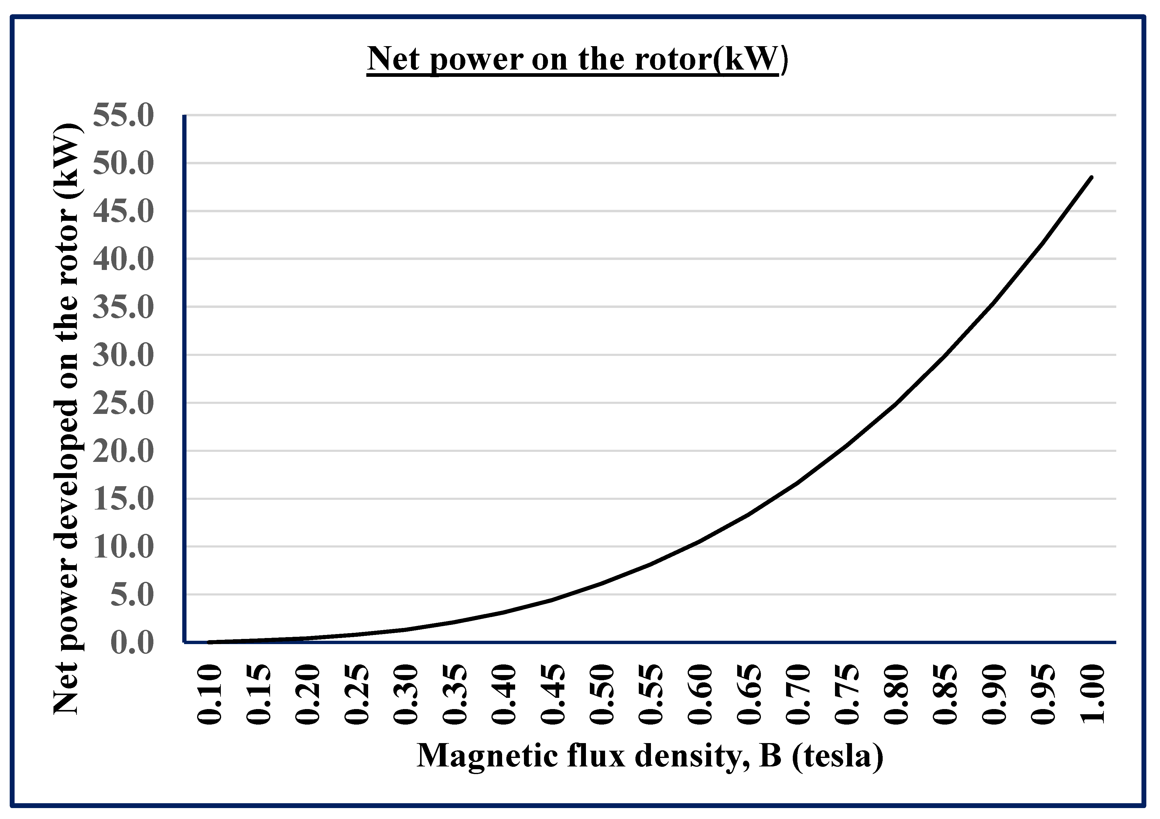

Table 1.
Estimated net power output for 8 poles having a magnetic efficiency of 75% , stator loss of 50% and 10% auxiliary power.
Table 1.
Estimated net power output for 8 poles having a magnetic efficiency of 75% , stator loss of 50% and 10% auxiliary power.
| Flux Density (Tesla) | Rotor Mass (kg) | Rotor Moment of Inertia (kg.m^2) | Pole strength (A.m) | Total magnetic potential energy (J) | Ideal rotor RPM | Total Magnetic Torque (N.m) | Total Magnet Power (kW) | Stator Power Loss (kW) | Auxiliary Power Loss (kW) | Net Rotor Power (kW) |
| 0.10 | 47.713 | 0.193 | 143.2 | 12.3 | 107.8 | 10.7 | 0.1 | 0.1 | 0.0 | 0.0 |
| 0.15 | 47.713 | 0.193 | 214.9 | 27.7 | 161.7 | 24.2 | 0.4 | 0.2 | 0.0 | 0.2 |
| 0.20 | 47.713 | 0.193 | 286.5 | 49.2 | 215.6 | 43.0 | 1.0 | 0.5 | 0.1 | 0.4 |
| 0.25 | 47.713 | 0.193 | 358.1 | 76.9 | 269.5 | 67.1 | 1.9 | 0.9 | 0.2 | 0.8 |
| 0.30 | 47.713 | 0.193 | 429.7 | 110.8 | 323.4 | 96.7 | 3.3 | 1.6 | 0.3 | 1.3 |
| 0.35 | 47.713 | 0.193 | 501.3 | 150.8 | 377.3 | 131.6 | 5.2 | 2.6 | 0.5 | 2.1 |
| 0.40 | 47.713 | 0.193 | 573.0 | 197.0 | 431.2 | 171.9 | 7.8 | 3.9 | 0.8 | 3.1 |
| 0.45 | 47.713 | 0.193 | 644.6 | 249.3 | 485.1 | 217.5 | 11.1 | 5.5 | 1.1 | 4.4 |
| 0.50 | 47.713 | 0.193 | 716.2 | 307.8 | 539.0 | 268.6 | 15.2 | 7.6 | 1.5 | 6.1 |
| 0.55 | 47.713 | 0.193 | 787.8 | 372.4 | 592.8 | 325.0 | 20.2 | 10.1 | 2.0 | 8.1 |
| 0.60 | 47.713 | 0.193 | 859.4 | 443.2 | 646.7 | 386.7 | 26.2 | 13.1 | 2.6 | 10.5 |
| 0.65 | 47.713 | 0.193 | 931.1 | 520.1 | 700.6 | 453.9 | 33.3 | 16.7 | 3.3 | 13.3 |
| 0.70 | 47.713 | 0.193 | 1002.7 | 603.2 | 754.5 | 526.4 | 41.6 | 20.8 | 4.2 | 16.6 |
| 0.75 | 47.713 | 0.193 | 1074.3 | 692.5 | 808.4 | 604.3 | 51.2 | 25.6 | 5.1 | 20.5 |
| 0.80 | 47.713 | 0.193 | 1145.9 | 787.9 | 862.3 | 687.5 | 62.1 | 31.0 | 6.2 | 24.8 |
| 0.85 | 47.713 | 0.193 | 1217.5 | 889.4 | 916.2 | 776.2 | 74.5 | 37.2 | 7.4 | 29.8 |
| 0.90 | 47.713 | 0.193 | 1289.2 | 997.2 | 970.1 | 870.2 | 88.4 | 44.2 | 8.8 | 35.4 |
| 0.95 | 47.713 | 0.193 | 1360.8 | 1111.0 | 1024.0 | 969.6 | 104.0 | 52.0 | 10.4 | 41.6 |
| 1.00 | 47.713 | 0.193 | 1432.4 | 1231.1 | 1077.9 | 1074.3 | 121.3 | 60.6 | 12.1 | 48.5 |
Disclaimer/Publisher’s Note: The statements, opinions and data contained in all publications are solely those of the individual author(s) and contributor(s) and not of MDPI and/or the editor(s). MDPI and/or the editor(s) disclaim responsibility for any injury to people or property resulting from any ideas, methods, instructions or products referred to in the content. |
© 2025 by the authors. Licensee MDPI, Basel, Switzerland. This article is an open access article distributed under the terms and conditions of the Creative Commons Attribution (CC BY) license (http://creativecommons.org/licenses/by/4.0/).
Copyright: This open access article is published under a Creative Commons CC BY 4.0 license, which permit the free download, distribution, and reuse, provided that the author and preprint are cited in any reuse.


