

Submitted:
21 October 2025
Posted:
21 October 2025
You are already at the latest version
Abstract
This paper presents the development of OpenCHIRP, an innovative subbottom profiler (SBP) designed for high-resolution seismic reflection surveys in shallow-water marine and lacustrine environments. The instrument employs chirped (frequency- modulated) im-pulses to penetrate the first few meters of sediments below the seafloor. Key characteristics include low cost, lightweight, and low energy consumption, making it particularly suita-ble for deployment onboard Autonomous Surface Vehicles (ASVs). We discuss design, functionality, and potential applications of this innovative instrument, as well as results of the preliminary tests. All information necessary to reproduce the OpenCHIRP isare in-cluded in this paper.
Keywords:
OpenCHIRP
; subbottom profiler
; CHIRP
; seismic reflection
; shallow-water environments
; pseudo-3D and 4D (repeated) seafloor and subseafloor seismic surveys
1. Introduction
CHIRP subbottom profilers (SBP) have evolved into essential tools for a wide range of underwater studies, including marine geology, archaeology, and engineering [1,2,3]. The stability characteristics of the waves generated by these systems make them effective for estimating seabed reflectivity, which could enable quantitative assessments for classification of the seafloor [4,5,6]. CHIRP sonars are widely used in many different fields, dealing with marine geology, stratigraphic reconstructions, and assessment of the sea- lake-floor physical conditions, either for scientific purposes, or for construction and detection of offshore infrastructures e.g., [7]. They are the first and probably most diffused instrumentations onboard of oceanographic vessels. 3D versions of CHIRP-sonar system have been developed and successfully tested during marine geophysical surveys [8,9,10].
A novel and promising application of CHIRP-sonars to geo-forensic searches in shallow-water environment is described in Ruffell et al. [11], who applied a technological solution introduced by Bandini et al. [12], which consists in attaching a commercially available fishing sonar, via a winch mechanism, to an aerial drone.
Unlike impulsive systems, CHIRP-sonars transmit mechanical energy from electroacoustic transducers into the medium using a frequency-modulated (FM) wavelet instead of impulsive or time-gated monotonic waves. This distinctive approach allows for greater penetration while maintaining high vertical resolution, which primarily depends on the frequency content of the source signal.
The transmitted and received signals are used to deconvolve, correlate, or apply a matched filter to the data, effectively reducing uncorrelated noise between the two signals in the received data [13]. The relatively long outgoing sweep is compressed, and the final signal is transformed into a conventional seismic signal with an improved signal-to-noise ratio [14,15,16]. Chirped SBP systems are effective in very shallow water due to the reduced sensitivity of the frequency-modulated signal to reverberations. However, in extremely shallow water conditions (<5 m), the typical configuration of coincident source and receiver may need modification, such as employing receiving transducers separated from the source. This adjustment is particularly critical for boomers and sparkers, requiring careful geometric configurations. Thanks to their high resolution and seismic signal repeatability, CHIRP systems are invaluable for stratigraphic correlations and reflectivity estimates [17], as demonstrated by field analyses which can be performed using readily available open-source software packages such as ChirCor [18] and SeisPrho [19].
Typically, sweep sources in CHIRP sonars operate within a frequency range from a few hundred Hz to tens of kHz. Gutowsky et al. [20] tested seven sweep types with various envelope functions and instantaneous frequency functions to identify the optimal wavelets. To obtain time-series data reflecting the velocity-density function of the substrate and generate acoustic imaging for inferring geological properties, it is essential to remove the sweep using algorithms like cross-correlation or by applying a matched filter based on the autocorrelation of the source wavelet (Klauder wavelet).
Following this process, the data is often presented as the envelope function of the seismic signal [13], forming a new complex trace consisting of the original data (real part) and the quadrature-phase data obtained through the Hilbert transform (imaginary part). This relatively intricate process of acquiring and processing seismic data, often performed in real-time by specialized and high-performance electronic devices, makes traditional SBP systems expensive, inflexible, and somewhat limited in user interaction.
We have designed an innovative CHIRP sonar system called OpenCHIRP, specifically tailored for seismic reflection surveys in shallow-water environments. The standout features of this system include its lightweight design, low power consumption, and extensive use of “open-architecture” electronic devices and “open-source” software routines. We anticipate that these characteristics will simplify the accessibility and understanding of this crucial tool among a broader community of scientists and pave the way for its integration into unmanned vehicles. Prototypes of OpenCHIRP were successfully tested onboard OpenSWAP [21] during multiple test sessions across various case studies, some of which are presented in this work.
2. Materials and Methods
At its core, a sub-bottom profiler functions in a relatively simple way: it generates a signal with specific length and frequency characteristics, emits it through a set of transducers at regular intervals (typically 4 to 16 times per second), and uses a hydrophone to receive the reflected signal from the underwater environment. The transducers are strategically placed just below the water’s surface and arranged to ensure that the emitted signal travels perpendicular to the seabed.
When the signal reaches the bottom, it experiences partial reflection and partial transmission. The transmitted portion penetrates deeper into the seabed, undergoing similar processes of partial reflection and transmission at each layer of varying density it encounters. This process allows the sub-bottom profiler to gather valuable information about the underlying layers of the seabed, including the geometry and terminations of reflectors, which can be used to infer details about depositional processes and environmental changes.
2.1. Hardware
Several models of SBP systems are available today, each fulfilling specific technical requirements based on the intended application (e.g., stratigraphy, archaeology, environmental studies). Each SBP system features a custom hardware design that includes the generation of an impulse or wavelet, which is sent to a power amplifier and transducer coupled with the water column.
While current technologies make the development of a sub-bottom profiler appear deceptively simple, there are real-world challenges to address:
Signal Quality and Power: The generated signal must be of high quality and have sufficient power to penetrate adequately beneath the seafloor.
Hydrophone Sensitivity: The hydrophone must be sensitive enough to accurately capture the weak reflected signal from the seafloor.
Noise Reduction: The hydrophone receives not only the reflected signal but also ambient acoustic noise; effective methods are needed to mitigate this interference.
Autonomous Operation: For use with autonomous vehicles, the instrument must be compact, low-power, and self-contained, capable of performing data acquisition without reliance on an external, powerful computer.
Addressing these challenges ensures the sub-bottom profiler’s effectiveness and reliability in real-world applications, particularly for autonomous underwater vehicles (AUVs).
To meet these technical specifications, we developed an all-in-one system incorporating as many open-hardware and open-source components as possible. The final system, described below, comprises an emitting system and an acquisition system. The acquisition system includes a compact computer that collects and stores data from the profiler in a standard format, geo-referenced with GPS-provided positions.
The OpenCHIRP system is designed to be compatible with unmanned systems, such as autonomous surface vehicles like the OpenSWAP vehicles [21], allowing for complete programmatic control of its functions. By utilizing open-hardware and open-software components, we ensure flexibility, transparency, and ease of customization. The emitting system integrates smoothly with the acquisition system to facilitate accurate and reliable data collection.
A compact computer within the acquisition system is essential for managing and organizing the collected information, ensuring accessibility. Precise geo-referencing, facilitated by GPS integration, is critical for applications requiring spatial accuracy. Moreover, OpenCHIRP’s compatibility with autonomous systems represents a significant opportunity, particularly in environments where manual control is impractical or impossible. The ability to programmatically control all aspects of the system adds a layer of automation that enhances efficiency and reduces the need for human intervention.
Overall, this approach not only fosters innovation through the use of open technologies but also provides a robust and versatile solution for a wide range of applications.
The hardware blocks of the SBP system are displayed in Figure 1.
2.1.1. Mainboard
By using open-hardware parts, maintenance is particularly straightforward in case of problems or failures. Open-hardware components are typically well-documented and widely supported by a community of developers and users. This accessibility ensures that replacements and repairs can be conducted efficiently and cost-effectively, minimizing downtime and enabling interventions even during operations in remote locations.
Additionally, the modularity and standardization inherent in open-hardware designs facilitate easy upgrades and modifications. If a particular component becomes obsolete or a new, improved version is released, it can often be swapped out without requiring a complete overhaul of the system. This flexibility provides a significant advantage over proprietary systems, which may require proprietary parts and specialized knowledge for maintenance.
As shown in the block diagram of Figure 1, the system primarily consists of a Raspberry Pi connected to an Arduino-DUE microcontroller. The Arduino-DUE performs the following tasks:
Receives, via its primary USB port, the start and end frequencies, the pulse length of the signal to emit, and the emission rate of the pulses.
-Builds the waveform to emit based on user parameters.
-Emits the waveform at the specified rate through one of its DAC ports.
-Simultaneously receives the signal from the hydrophone and sends it to its secondary USB port.
The Raspberry Pi performs the following tasks:
-Instructs the Arduino-DUE on the signal to emit.
-Collects data sent by the Arduino-DUE.
-Acquires real-time position data from a GPS device.
-Saves the geo-referenced data in a standard format on a USB disk.
To properly manage the emitted and received signals, the microcontroller requires signal conditioning electronics for input and output amplification.
The Raspberry Pi, Arduino-DUE, necessary voltage-processing electronics, and additional features are all arranged on the OpenCHIRP main board (Figure 2), designed using the free ECAD software Altium CircuitMaker.
The main features of this board are here briefly reported:
- fused power supply equipped for external input of 5 and 12V;
- Raspberry Pi and Arduino-DUE slot for easy access and maintenance;
- hydrophone signal processing: custom voltage adjustment and gain amplifier programmable in real-time by the Arduino-DUE;
- expansion ports for additional integrations.
The OpenCHIRP main board schematic is reported in Figure 2, and includes three sections:
i. A supply section (box A - Figure 2), designed to accept both 5 and 12V on two separate rails and using a pre-crimped 4-pin connector. Decoupling and bypass capacitors are added, as well as interchangeable bottle fuse (default 3A) and an SMD led for power-on tracking. No reverse polarity protection is provided in this board release.
ii. A specific low-noise regulated voltage section (box B - Figure 2), dedicated to the signal conditioning section (box C – Figure 2, described in iii.). This section, along with the connected signal conditioning part (iii.), ensures that interferences and noise affecting the hydrophone signal are kept as low as possible, thus enhancing the signal quality. The circuit design, along with the selection of components and integrated circuits (ICs) has been made to receive a signal from the hydrophone in the [6±3] V range, and it can be easily reconfigured for different input signal ranges. Low-noise and low-dropout voltage regulators from LT technologies have been selected (for 5V – IC U1A and 3.3V – IC U3A) considering their market availability and their package (MSOP); the latter allows easy component swap and circuit reconfiguration. The IC U2 provides the -5V voltage necessary for the proper signal conditioning (iii.). Passive components (C, R, L) are here used following manufacturers’ suggestions to make the regulation circuit properly work. Service test points are included on the PCB layout to check the regulated voltages.
iii. A conditioning section for the hydrophone signal (box C – Figure 2) that provides voltage adjustment and amplification of the input signal, labeled on the schematic as AN_IN, coming from a 2-pin pre-crimped connector. The hydrophone signal is first fed to IC U4, a single-channel operational amplifier (rail-to-rail and high voltage span, for potential system reconfiguration), used as a voltage buffer (for signal stabilization and impedance matching). It is connected to a first-order high-pass filter with a cutoff frequency of about 400 Hz. The filter and its capacitor block the DC offset, so the signal input to op-amp U5 is in the [0±3] V range. U5, in inverting configuration, provides the first hardware signal amplification according to the JP6 jumper position. R2 and R3 resistors define the amplification factor, by default 0.68x (via R2) and 10x (via R3). Then, software amplification, controlled by the Arduino DUE board, is applied through IC U6: a programmable gain inverting amplifier (LTC6910, gain 0÷64, selected via 3 digital signals). The signal is then shifted around 1.65V (op-amp U7A; U7 is a dual-channel, rail-to-rail, low-noise operational amplifier LTC6910) to ensure proper reading by the Arduino DUE Analog-to-Digital Converter. The shifted signal passes through a first-order low-pass filter (cutoff frequency about 52 kHz) and a voltage buffer (U7B) before being wired to the Arduino DUE at label A0_A2. Service test points are placed in section iii, as well as exposed ground pads to add a ground shield and reduce external interference. Bypass and decoupling capacitors are placed for all the ICs used.
iv. The Arduino DUE, Raspberry Pi, and additional connectors section (all parts not included in BOX A, B, and C – Figure 2) includes headers for easy maintenance and substitution of the Arduino and Raspberry Pi, as well as multiple connectors for customization and feature expansion. The available expansion ports are: 1x RS232 port, 3x UART ports, 2x analog inputs (0-3.3V), and 2 TTL digital I/O. Status LEDs are connected to the digital I/O of the Raspberry Pi and Arduino to provide information about the proper system operation. An additional header connector is also placed on the PCB to ensure compatibility with previous OpenSWAP hardware and for debugging purposes.
The components mounted primarily on the top of the board enable easy maintenance and part replacement, while the PCB form factor (Eurocard 10x16 cm with additional M3 mounting holes) provides numerous options for placing and securing the board.
This board will be released under an open-hardware license, and the routed PCB along with a 3D rendering of the board are shown in Figure 3.
2.1.2. Seismic Reflection Signal Generation System
The system features a combined emitting and receiving electronic setup designed for generating and detecting seismic reflection signals from the sedimentary sequence. It operates using two different electronic configurations and types of transducers: one is a commercially available system, and the other is a custom-designed solution.
Commercial System: this configuration employs an off-the-shelf electronic driver paired with a standard underwater transducer. It is optimized for reliability and ease of integration, ensuring consistent signal output with minimal calibration needed.
Custom System: this second configuration consists of a specially designed electronic driver paired with a custom transducer. This system provides enhanced control over signal characteristics, such as frequency, pulse shape, and energy output, thereby optimizing performance for specific seismic exploration requirements.
Both systems are designed to produce controlled acoustic pulses that travel through the water and reflect off subsurface layers, allowing for high-resolution seismic imaging. The integration of commercial reliability with custom flexibility offers a versatile solution for underwater seismic studies.
All experiments utilized the same receiving unit, which consisted of a hydrophone and a preamplifier. However, two different emission units were employed, each comprising a transducer and an amplifier. The peripheral devices used in the tests are detailed in Table 1.
Table 1 displays the peripheral devices that were tested, along with the interconnection scheme for both testing configurations. It emphasizes the differences in the emission units while keeping the receiving setup consistent.
Both, transmitter and receiver transducers were hosted in a hydrodynamic vessel designed for the purpose of mounting the OpenCHIRP transducers onboard an Autonomous Surface Vehicle (Figure 4)
2.2. Software
The software system consists of two primary components: the Arduino-DUE firmware, known as OpenCHIRP, and a Raspberry Pi program called CiapCiap. The firmware is developed in C++ and uploaded to the controller using the Arduino IDE, while CiapCiap is also written in C++ and operates on a Linux distribution, specifically Arch Linux, for the Raspberry Pi.
This paper does not provide a detailed analysis of the source code for these two programs but instead outlines their main features and usage. Readers can access the source code, as both programs are released under the GPL license.
Additionally, the software system includes the Arch Linux operating system running on the Raspberry Pi. It has been configured for unmanned operation, focusing on maximizing fault tolerance and enabling automatic shutdown and restart in the event of temporary malfunctions. This feature is especially important for deploying the instrument in autonomous vehicles.
2.2.1. The Firmware
This software operates within an Arduino DUE microcontroller. The Arduino DUE features two USB ports: one designated as the “Native port” and the other as the “Programming port.” The “Native port” is significantly faster and is therefore utilized for receiving the acquired data back. Meanwhile, the other USB port is employed for transmitting commands and parameters to the Arduino to configure the low-level acquisition process. Figure 5 illustrates the block diagram of the program.
Two additional ports of the Arduino-DUE are utilized:
-The DAC0 (Digital Analog Converter) port for emitting the waveform towards the amplified transducers.
-The ADC (Analog Digital Converter) A0 port for sampling the signal received by the hydrophone.
Upon startup, the program flow enters an infinite loop, awaiting commands. Although the command set is small, it enables control over all necessary aspects to program the emission and acquisition processes. The commands and parameters are listed in Table 2.
2.2.2. The CiapCiap Program
It is the main software used for acquisition and control, providing extensive management of the emission and acquisition processes through two configuration files that contain commands and parameters for the Arduino-DUE microcontroller. This program starts automatically during the Raspberry Pi’s boot sequence. It reads the two configuration files, “params” and “commands.chirp,” and then begins the acquisition process. The software’s block diagram is shown in Figure 6.
The CiapCiap code is entirely configured through these two files, devoid of any graphical user interface. However, this absence of a GUI should not pose an issue, given that the program is intended for use in remote vehicles. Upon startup, the program searches for a file named “params” in the current directory, thereafter configuring all operations based on the contents of that file. Although the block diagram appears simple, the software itself is quite complex. It requires time to thoroughly explore the parameters in the configuration files and understand their functions. The full source code of the CiapCiap program is available at: https://gitlab.com/giuseppe.stanghellini/ciapciap
2.2.3. The “Params” File
This file is structured in a position-dependent manner, where each individual line is designated to specify a distinct parameter. CiapCiap starts the reading process with the expectation that each line will consistently contain the correct parameter. Consequently, if there are any lines missing, CiapCiap will encounter problems, resulting in the file not being interpreted correctly. To elaborate, each line is composed of values that are intended to be assigned to the parameter corresponding to that specific line. These values are followed by one or more spaces and, optionally, a ‘#’ character. Should this character be present, it serves as an indicator that any subsequent characters extending to the end of the line are to be disregarded and treated as non-executable comments by CiapCiap. In Appendix A, a line-by-line description of the parameters file is reported.
2.2.4. The Hosting Operating System
The Raspberry Pi running the acquisition jobs uses an Arch Linux distribution for ARM microprocessors. The installation is minimal, not requiring any desktop environments or graphical user interfaces. It is configured to auto-login as the root user and start all services and acquisition processes. System images are freely available for download.
The system is configured entirely by configuration files inside the /boot/OPENSWAP folder. This folder is mounted read-only to preserve it in case of unexpected reboot/freeze of the system. All file systems, except /DATA, are mounted read-only to preserve their integrity. To modify files on those file systems, a four-step sequence is required:
- 1)
- Login by SSH to the OpenCHIRP.
- 2)
- Execute RW.SH to make the folder writable.
- 3)
- Edit the files for acquisition parameters.
- 4)
- Kill ciapciap.
- 5)
- Execute RO.SH to make the folder read-only again.
2.2.5. The Boot Process
When powered on, the Raspberry Pi automatically logs in as the root user, causing the profile file inside the /root folder to be executed by the bash shell. This file executes the /boot/OPENSWAP/autostart.sh script, which spawns several processes and runs the following shell scripts:
-prologue.sh: Prepares the execution environment, sets global environment variables, and checks existing file systems for consistency.
-start_net.sh: Starts the network and configures the access point.
-start_acq.sh: Starts the acquisition process.
3. Results
In order to test the performance of OpenCHIRP, we installed it onboard an Autonomous Surface Vehicle of the OpenSWAP class, and carried out several test sessions in a small, shallow-water alpine lake, the Lake of Cavazzo, during geo-environmental studies [22]. This enabled us to perform a fine-tuning of source and receiver configurations, and test the optimal parameters, such as geometry of the transducers, sweep length, and operating frequency range. Figure 7 displays an example of the seismic reflection profiles collected in about 20 m of water depth in the Lake of Cavazzo.
It shows a penetration of the signal reaching over 10 m below the lake’s floor, and includes three main steps of data processing, including the raw-data plot (Figure 7a), which shows a low signal-to-noise ratio due to the presence of environmental noise and the absence of a de-chirp processing applied to the data. Figure 7b shows the same section but after de-chirping, and allows to identify seismic reflection with centimetric resolution. Typical representation of CHIRP sub-bottom profile is in form of Instantaneous Amplitude of the signal, as shown in Figure 7c.
We then performed some tests using two different emitter/receiver configurations.
Setup-1
In the initial phase of testing, the emitting transducer consisted of three sound exciters (see Table 1) connected in series and driven by a 1500W Class D amplifier. This configuration operated within a frequency range of 1 kHz to 10 kHz, adhering to the performance limits of the amplifier-transducer assembly. Under these conditions, a frequency-modulated “chirped” pulse ranged between 2 and 7 kHz.
Setup-2
The second phase of testing employed a commercially available piezoelectric transducer designed for underwater applications (see Table 1). This transducer was driven by dedicated control electronics, which functioned as both an impedance transformer and an amplification stage. In this configuration, the system operated at higher frequencies, ranging from 10 kHz to 25 kHz. Within this range, two different modulation settings were applied to the emitted pulse: one between 10 kHz and 15 kHz and the other between 20 kHz and 25 kHz.
Figure 8 reports results obtained using the two configurations, Setup-1 and -2, which led to obtain comparable results both in term of vertical resolution and penetration of the seismic signal.
We note that the different setups allow for detecting similar stratigraphic information, although Setup-1 shows a deeper penetration of the signal. Conversely Setup-2 shows a higher resolution in the upper part of the section due to the higher frequency content.
We also performed a comparison between a commercial system, i.e., the Teledyne Benthos CHIRP III sub-bottom profiler with our OpenCHIRP, in imaging the shallow subsurface in Lake Trasimeno (Central Italy) during a seismostratigraphic survey [23]. Figure 9 display results of this comparison, which led to similar performances regarding penetration and resolution. But while the CHIRP III system was operated using a normal boat due to its dimensions and energy consumption, OpenCHIRP operated onboard of an OpenSWAP vehicle.
The availability of CHIRP-sonar systems that could be employed onboard Autonomous Surface Vehicles opens the door to pseudo-3D and 4D (repeated) seismic reflection and bathymetric surveys of shallow-water environments, such as coastal lagoons, beaches, and lakes, and could contribute to quantitatively evaluate the effects of anthropic and natural pressures. Moreover, the low-cost and the open architecture of OpenCHIRP might enlarge the potential community of users, including Universities, Oceanographic Institutes, and Environmental Agencies, which find in the relatively high costs of purchase and maintenance of such devices a great obstacle that can be rarely overcome.
5. Conclusions
This study presented a successful design, implementation, and testing of a novel sub-bottom profiler (SBP) optimized for high-resolution seismic reflection surveys in shallow-water environments. By employing CHIRP (frequency-modulated) impulses, the developed SBP achieves effective sediment penetration while maintaining a compact, lightweight, and energy-efficient design. These characteristics make it an ideal instrument to be integrated with Autonomous Surface Vehicles (ASVs), enhancing their capability to perform detailed subsurface investigations in both marine and lacustrine settings.
Results of the preliminary tests confirm the SBP’s efficacy in achieving high-resolution subsurface imaging, validating the core design principles and operational goals. Its low-cost and energy-efficient features ensure accessibility and broad applicability, paving the way for widespread adoption in geophysical research, environmental monitoring, and resource exploration.
Furthermore, the comprehensive details provided in this paper ensure that the SBP can be reproduced and adapted to suit diverse research needs. By sharing the design and operational insights, this work invites further innovation and optimization by the broader scientific community.
In summary, the development of this innovative SBP represents a significant step forward in seismic survey instrumentation. It addresses critical needs for cost-effectiveness, portability, and compatibility with modern unmanned systems. Future work will focus on expanding its capabilities, such as enhancing sediment penetration depth and exploring additional functionalities, to further broaden its application potential. This advancement underscores the potential for innovative engineering solutions to transform the field of shallow-water seismic surveys.
Author Contributions
For research articles with several authors, a short paragraph specifying their individual contributions must be provided. The following statements should be used “Conceptualization, L.G. and G.S.; methodology, G.S., F.S.; software, G.S.; validation, G.S., F.D.B, F.S.; data curation, L.G., G.S., F.D.B.; writing—original draft preparation L.G.; writing—review and editing, all authors; visualization, all authors; supervision, G.S., L.G.; project administration, G.S., L.G.; funding acquisition, L.G., G.S. All authors have read and agreed to the published version of the manuscript.” Please turn to the CRediT taxonomy for the term explanation. Authorship must be limited to those who have contributed substantially to the work reported.
Funding
This research was funded by ECOSISTER, Next Generation EU (https://ecosister.it/).
Data Availability Statement
We encourage all authors of articles published in MDPI journals to share their research data. In this section, please provide details regarding where data supporting reported results can be found, including links to publicly archived datasets analyzed or generated during the study. Where no new data were created, or where data is unavailable due to privacy or ethical restrictions, a statement is still required. Suggested Data Availability Statements are available in section “MDPI Research Data Policies” at https://www.mdpi.com/ethics.
Acknowledgments
In this section, you can acknowledge any support given which is not covered by the author contribution or funding sections. This may include administrative and technical support, or donations in kind (e.g., materials used for experiments).
Conflicts of Interest
Declare conflicts of interest or state “The authors declare no conflicts of interest.” Authors must identify and declare any personal circumstances or interest that may be perceived as inappropriately influencing the representation or interpretation of reported research results. Any role of the funders in the design of the study; in the collection, analyses or interpretation of data; in the writing of the manuscript; or in the decision to publish the results must be declared in this section. If there is no role, please state “The funders had no role in the design of the study; in the collection, analyses, or interpretation of data; in the writing of the manuscript; or in the decision to publish the results”.
Abbreviations
The following abbreviations are used in this manuscript:
| MDPI | Multidisciplinary Digital Publishing Institute |
| DOAJ | Directory of open access journals |
| ASV | ASV Autonomous Surface Vehicle |
| SBP | Subbottom Profiler |
Appendix A
NAME/TYPE STRING: The name of the instrument, typically CHIRP.
INPUT UDP PORT/TYPE NUMERIC: The port to listen for incoming commands. An external program can send commands to CiapCiap to control the acquisition process.
UDP PORT OF MONITORING APP/TYPE NUMERIC: The port to send received data for remote monitoring. When CiapCiap acquires new data, it stores it in SEGY format inside the internal storage device and then sends a subset of that data to a listening application over the Internet (or intranet).
TCP/IP ADDRESS OF MONITORING APP/TYPE IP_ADDRESS: The IP address of the host running the monitoring application.
TRACES DECIMATION/TYPE NUMERIC: The traces decimation factor. This parameter specifies how many of the traces collected during the acquisition process must be sent to the listening application over the Internet, allowing to limit the outgoing traffic.
DATA DECIMATION/TYPE BOOLEAN: The data decimation factor. This parameter allows for further reduction of the data sent over the Internet. If the value 1 is specified, the trace will be resampled to 512 bytes before sending it.
DATA FOLDER/TYPE STRING: The directory where SEGY files are stored.
FILENAME PREFIX/TYPE STRING: The prefix of the filename of the stored data. The full filename includes a date stamp, time stamp, and the suffix “.SEG.”
SPLIT EVERY BYTES/TYPE NUMERIC: The maximum allowed size in bytes of a file.
μChirp COMMANDS FILE/TYPE STRING: The filename containing commands to set the μChirp parameters.
UNUSED
UNUSED
DUNVAG SERIAL DEVICE/TYPE PATH: The device to which the OpenSWAP vehicle is connected. Used when installed inside an OpenSWAP autonomous vehicle.
BAUD/TYPE NUMERIC: The baud rate of the serial connection to Dunvag.
DATA BITS/TYPE NUMERIC: The data bits of the serial connection to Dunvag.
PARITY/TYPE CHAR: The parity of the serial connection to Dunvag.
STOP BITS/TYPE NUMERIC: The stop bits of the serial connection to Dunvag.
GPS SERIAL DEVICE/TYPE PATH: The device to which the GPS is connected.
BAUD/TYPE NUMERIC: The baud rate of the serial connection to GPS.
DATA BITS/TYPE NUMERIC: The data bits of the serial connection to GPS.
PARITY/TYPE CHAR: The parity of the serial connection to GPS.
STOP BITS/TYPE NUMERIC: The stop bits of the serial connection to GPS.
BOTTOM TRACKING START SEARCH/TYPE NUMERIC: The starting point to search the bottom in ms. This parameter must be set to -1 for sub-bottom operation to disable bottom-tracking.
STEP_FUNCTION_LENGTH/TYPE NUMERIC: The step function length in the number of samples to use for bottom tracking. Unused for sub-bottom operation. 25-30. Unused Parameters for bottom tracking.
GPS PORT/TYPE NUMERIC: The port at which to start a GPS service.
References
- Bull, J.M.; Quinn, R.; Dix, J.K. (1998). Reflection Coefficient Calculation from Marine High-Resolution Seismic Reflection (CHIRP) Data and Application to an Archaeological Case Study. Marine Geophysical Researches 20, 1–11. [CrossRef]
- Plets, R.M.K.; Dix, J.K.; Adams, J.R; Best, A.I., (2008). 3D reconstruction of a shallow archaeological site from high-resolution acoustic imagery: The Grace Dieu, Applied Acoustics, 69-5, 399-411. [CrossRef]
- Boldreel, L.O.; Grøn, O.; Tayong, R.B.; Madsen, B.; Bennike, O.; Andersen, M.S. (2025). A Submerged and Buried Mesolithic Site off Svanemøllen Harbor, Copenhagen, Denmark: Acoustic Detection (Human-Altered Lithic Detection) and Verification by Means of Coring. Remote Sens., 2025, 17, 413. [Google Scholar] [CrossRef]
- Schock, S.G.; LeBlanc, L.A.; Satchidanarda P. (1992). Sediment Classification Using the CHIRP Sonar. Offshore Technology Conference, Houston, Texas, May 1992. [CrossRef]
- Schock, S.G.; LeBlanc, L.R.; and Mayer L.A. (1989). CHIRP subbottom profiler for quantitative sediment analysis. Geophysics, 54, 445–450. [CrossRef]
- Rakotonarivo, S.; Legris, M.; Desmare, R.; Sessarego, JP; Bourillet,J-F (2011). Forward modeling for marine sediment characterization using CHIRP sonars. Geophysics, 76, 4, T91–T99. [CrossRef]
- Zhang, T.; Wan, L.; Zeng, Wj. et al. (2012). Object detection and tracking method of AUV based on acoustic vision. China Ocean Eng, 26, 623–636. [CrossRef]
- Bull, J.M., Gutowski, M., Dix, J.K. et al. (2005). Design of a 3D CHIRP Sub-bottom Imaging System. Mar Geophys Res, 26, 157–169. [CrossRef]
- Gutowski, M.; Bull, J.M.; Dix, J.K.; Henstock, T.J.; Hogarth, P.; Hiller, T.; Leighton, T.G.; White, P.R. (2008). 3D high-resolution acoustic imaging of the sub-seabed. Applied Acoustics, 69, 3, 262-271. [CrossRef]
- Shin, J.; Ha, J.; Chun, JH; et al. (Field application of 3D CHIRP for geological surveys of shallow coastal regions. Mar Geophys Res 43, 13 (2022). [CrossRef]
- Ruffell, A.; Lally, A.; Rocke, B. Dronar—Geoforensic Search Sonar from a Drone. Forensic Sci. 2021, 1, 202–212. [Google Scholar] [CrossRef]
- Bandini, F.; Olesen, D.; Jakobsen, J.; Kittel, C.M.M.; Wang, S.; Garcia, M.; Bauer-Gottwein, P. Bathymetry observations of inland water bodies using a tethered sing-beam sonar controlled by an Unmanned Aerial Vehicle. Hydrol. Earth Syst. Sci. 2008, 25, 4549–4565. [Google Scholar] [CrossRef]
- Henkart, P. (2006). CHIRP sub-bottom profiler processing-a review. Sea Technology, 47(10), 35-38.
- Quinn R., Bull J.M., Dix J.K. (1988). Optimal processing of marine high-resolution seismic reflection (CHIRP) data. Mar. Geophys. Res., 20, 13-20.
- Baradello, L.; Carcione J.M. (2008). Optimal seismic-data acquisition in very shallow water. Surveys in the Venice lagoon. Geophysics, 73 (6), Q59-Q63. [CrossRef]
- Baradello, L. (2014). An improved processing sequence for uncorrelated CHIRP sonar data. Mar Geophys Res 35, 337–344. [CrossRef]
- Gasperini, L. (2005). Extremely Shallow-water Morphobathymetric Surveys: The Valle Fattibello (Comacchio, Italy) Test Case. Mar. Geophys. Res. 2005, 26, 97–107. [CrossRef]
- Dal Forno G. and Gasperini L. (2008). ChirCor: a new tool for generating CHIRP-sonar seismograms. Computer&Geosciences, 34, 103-114. [CrossRef]
- Gasperini, L.; Stanghellini, G. (2009). SeisPrho: An interactive computer program for processing and interpretation of high-resolution seismic reflection profiles. Computer&Geosciences, 35, 1497–1507. [CrossRef]
- Gutowski, M., Bull, J., Henstock, T. et al. (2002). CHIRP sub-bottom profiler source signature design and field testing. Marine Geophysical Researches, 23, 481–492. [CrossRef]
- Stanghellini, G.; Del Bianco, F.; Gasperini, L. (2020). OpenSWAP, an Open Architecture, Low Cost Class of Autonomous Surface Vehicles for Geophysical Surveys in the Shallow Water Environment. Remote Sensing, 12, 2575. [CrossRef]
- Polonia, A., Albertazzi, S., Bellucci, L.G., Bonetti, C., Bonetti, J., Giorgetti, G., Giuliani, S., López Correa, M., Mayr, C., Peruzza, L., Stanghellini, G., Gasperini, L. (2021). Decoding a complex record of anthropogenic and natural impacts in the Lake of Cavazzo sediments, NE Italy, Science of The Total Environment, 147659. [CrossRef]
- Gasperini, L.; Peteet, D.; Bonatti, E.; Gambini, E.; Polonia, A.; Nichols, J.; Heusser, L. (2022). Late Glacial and Holocene environmental variability, Lago Trasimeno, Italy, Quaternary International, 622, 21-35. [CrossRef]
Figure 1.
Hardware blocks of OpenCHIRP SBP system.
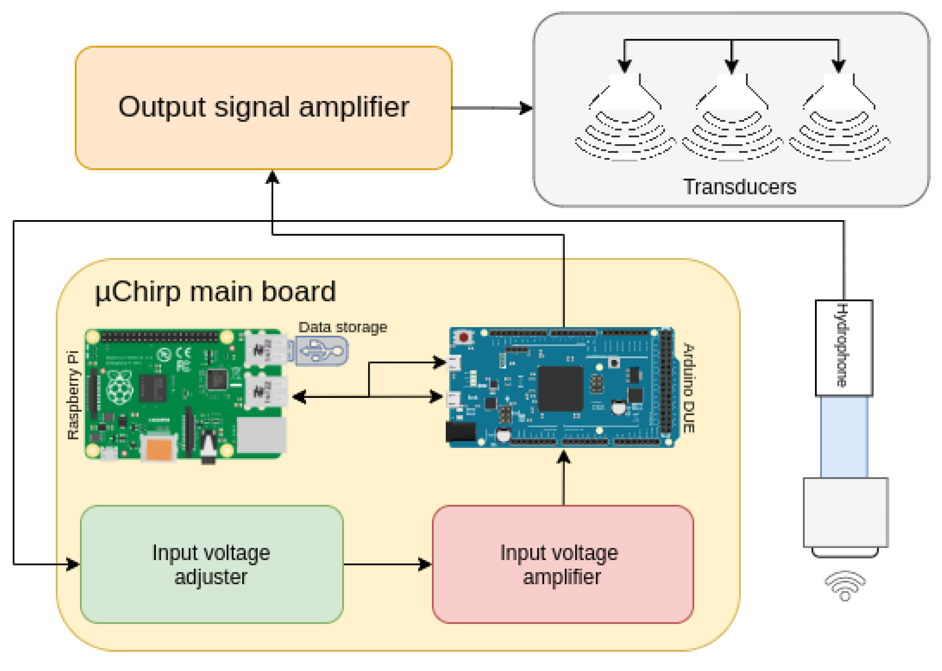
Figure 2.
Schematic of the OpenCHIRP main board.
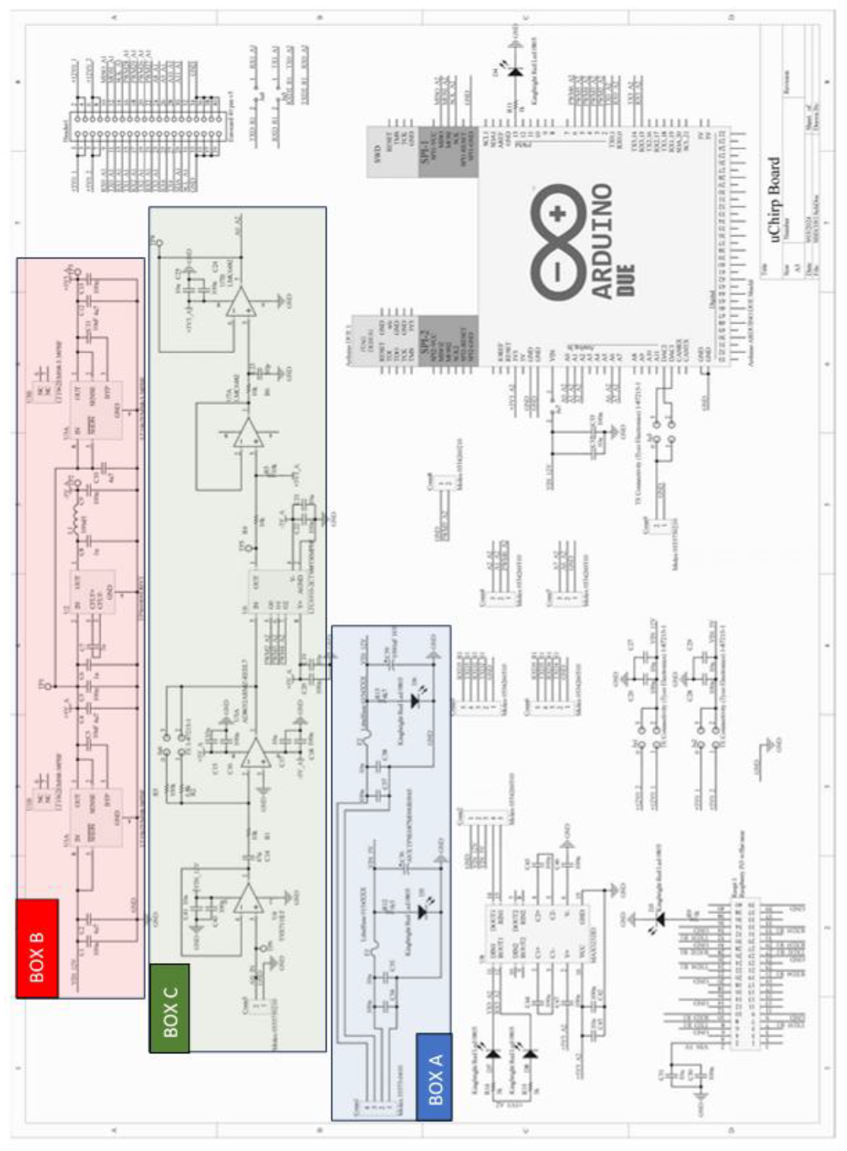
Figure 3.
Main PCB of the OpenChirp SBP, which includes all components for the signal conditioning and I/O, as well as the connectors for Arduino and Raspberry boards.
Figure 3.
Main PCB of the OpenChirp SBP, which includes all components for the signal conditioning and I/O, as well as the connectors for Arduino and Raspberry boards.
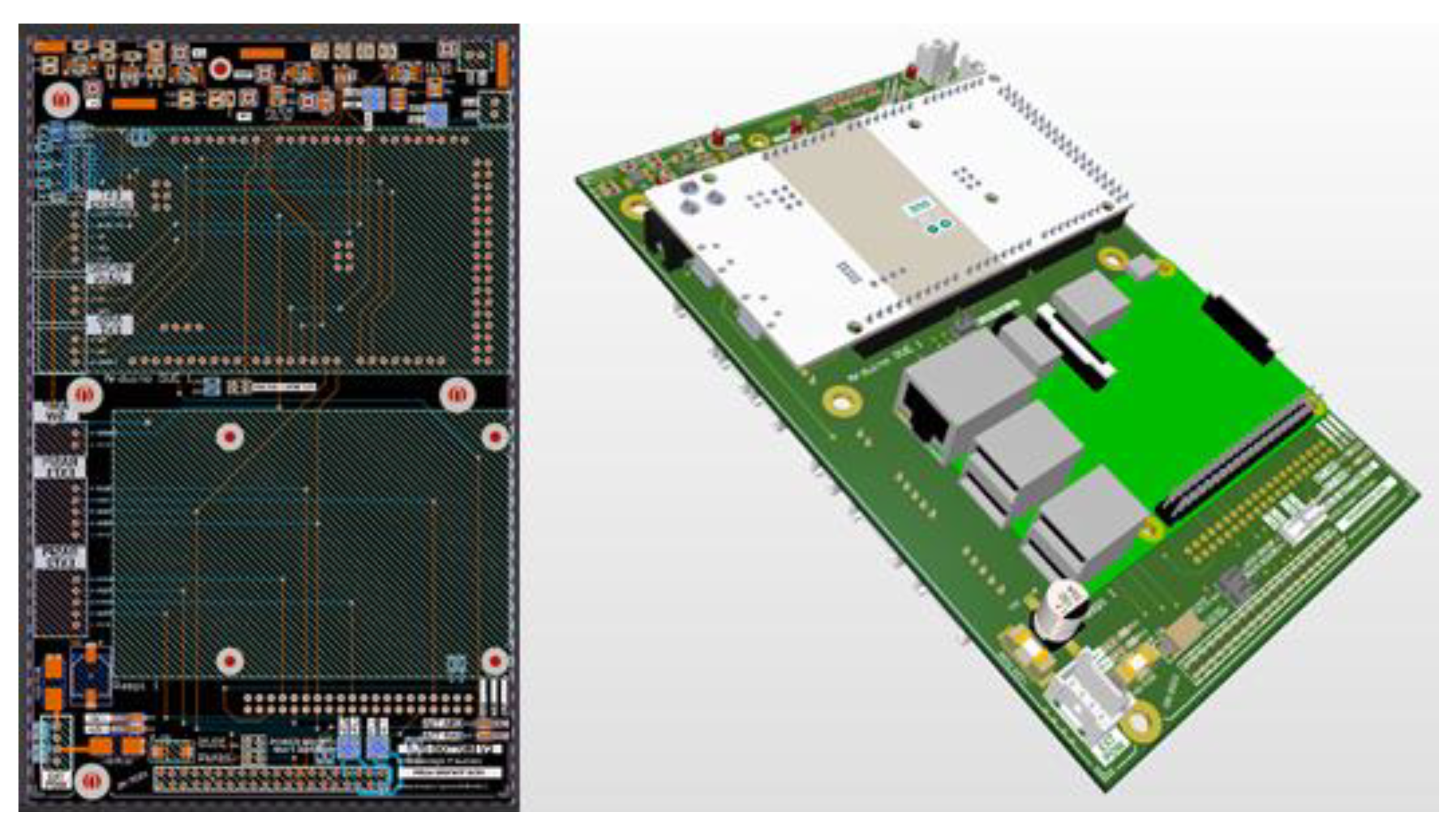
Figure 4.
Prototypes of the transducer vessel with the two transducers mounts.
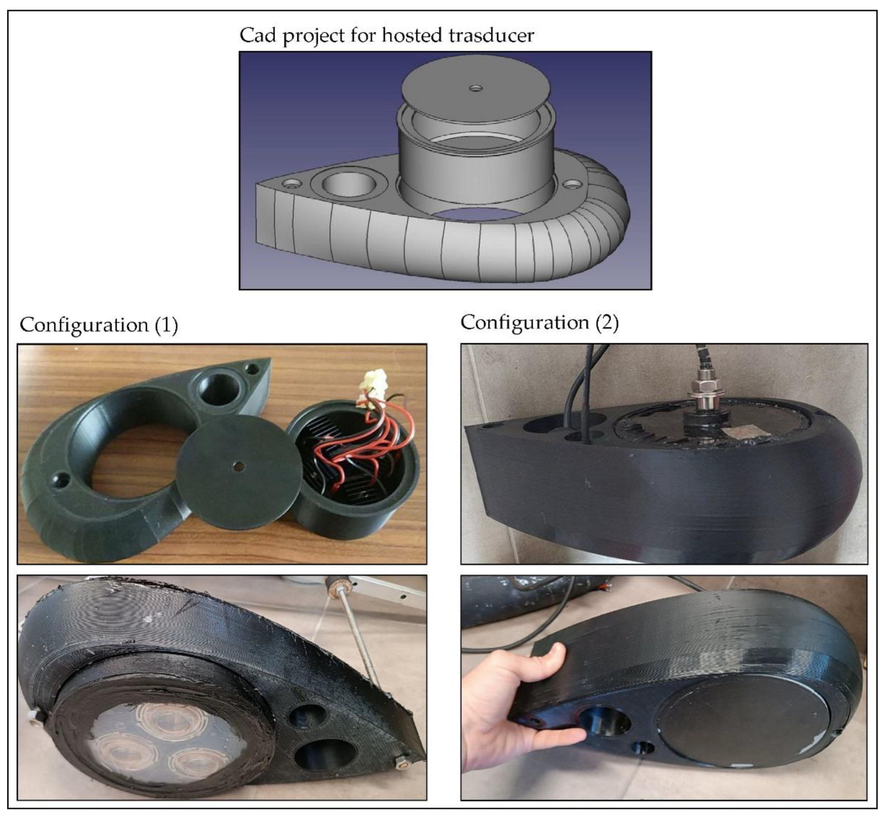
Figure 5.
Block diagram of the OpenCHIRP firmware.
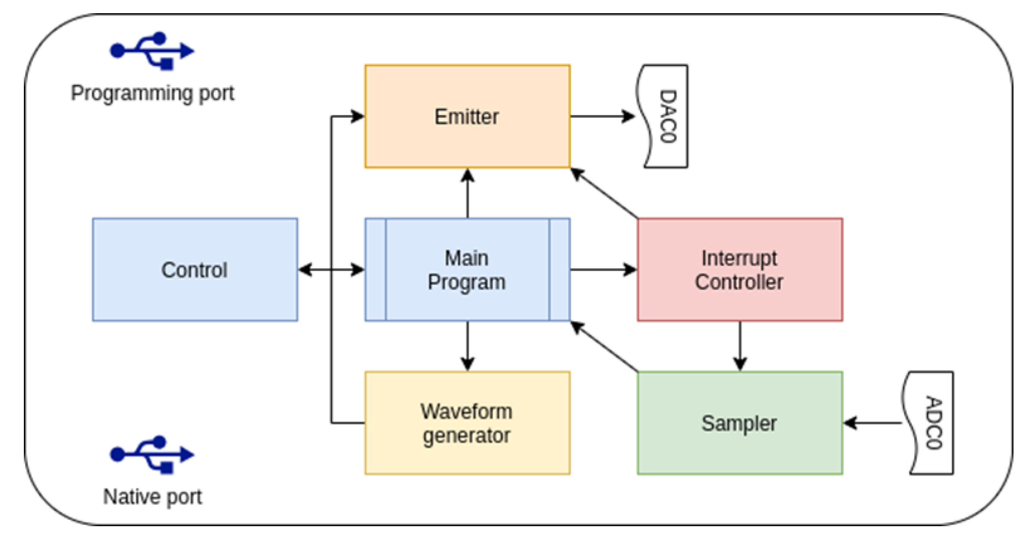
Figure 6.
Block diagram of acquisition program CiapCiap.
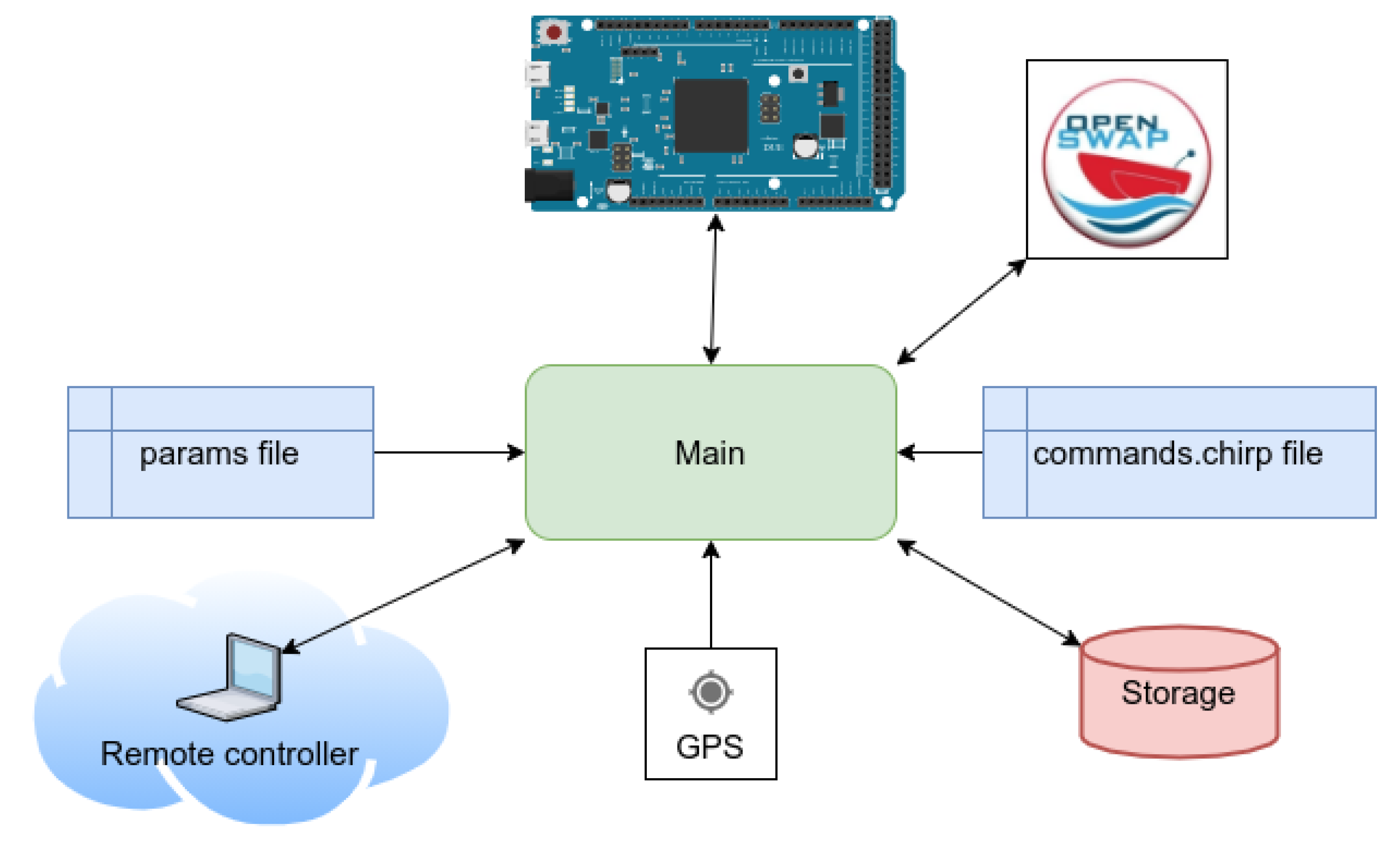
Figure 7.
Example of high-resolution seismic reflection profile collected in an Alpine Lake (Lake of Cavazzo, NE Italy) using the OpenCHIRP system mounted onboard an OpenSWAP vehicle. a) raw data; b) after de-chirping; c) after application of an instantaneous amplitude correction.
Figure 7.
Example of high-resolution seismic reflection profile collected in an Alpine Lake (Lake of Cavazzo, NE Italy) using the OpenCHIRP system mounted onboard an OpenSWAP vehicle. a) raw data; b) after de-chirping; c) after application of an instantaneous amplitude correction.
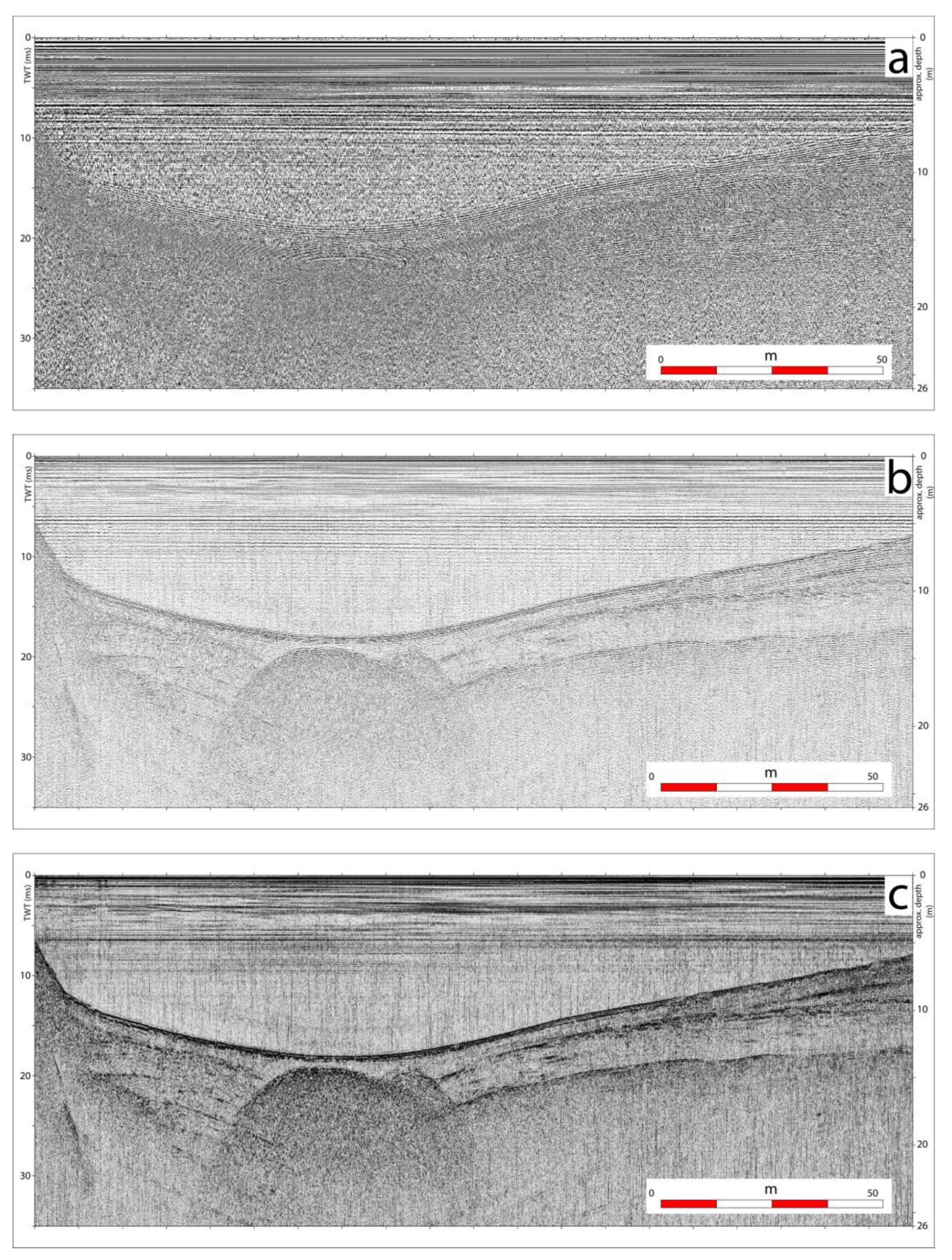
Figure 8.
a,b: seismic reflection profile collected using Setup-1, before (a) and after (b) application of Instantaneous Amplitude correction; c,d: same profile collected unit Setup-2.
Figure 8.
a,b: seismic reflection profile collected using Setup-1, before (a) and after (b) application of Instantaneous Amplitude correction; c,d: same profile collected unit Setup-2.
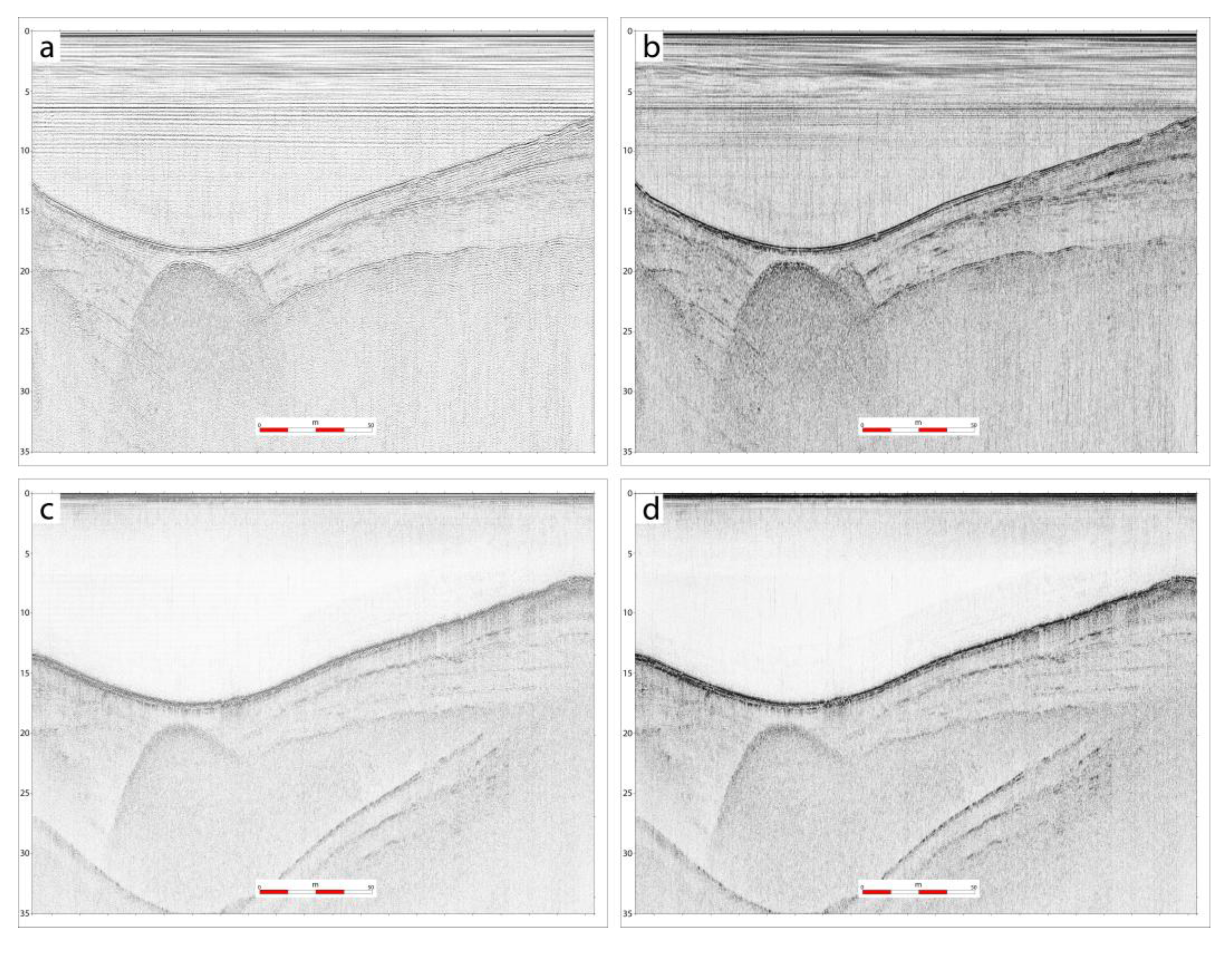
Figure 9.
An example of seismic reflection profiles along the same navigation line collected with two different systems in Lake Trasimeno (Central Italy). Top: CHIRP III Teledyne-Benthos, with 4 Massa transducers; Bottom: OpenCHIRP in configuration Setup-1. Unconsolidated sediments are penetrated down to 15–20 ms TWT below the lake floor, by both systems, with high vertical resolutions (tens of cm), enabling a detailed imaging of the sedimentary sequence.
Figure 9.
An example of seismic reflection profiles along the same navigation line collected with two different systems in Lake Trasimeno (Central Italy). Top: CHIRP III Teledyne-Benthos, with 4 Massa transducers; Bottom: OpenCHIRP in configuration Setup-1. Unconsolidated sediments are penetrated down to 15–20 ms TWT below the lake floor, by both systems, with high vertical resolutions (tens of cm), enabling a detailed imaging of the sedimentary sequence.
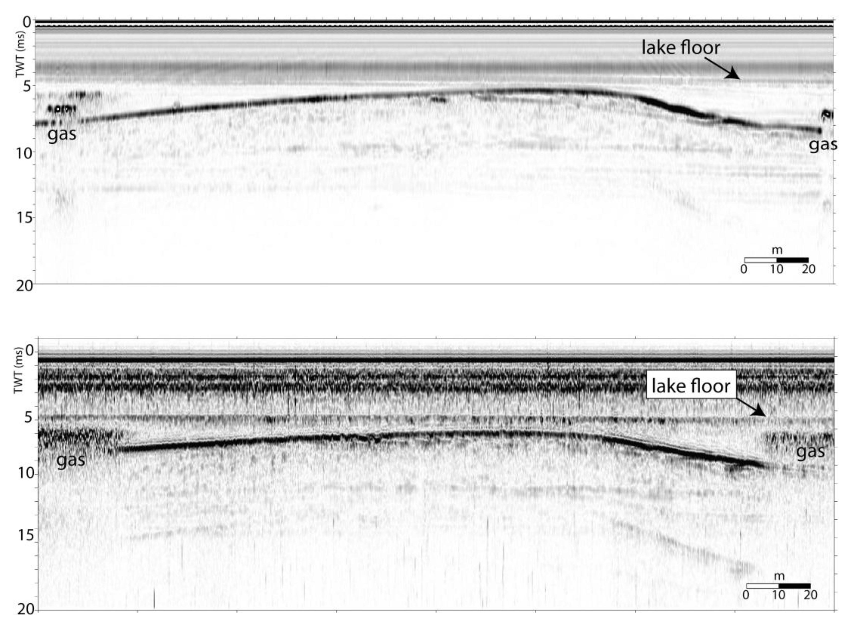

Table 1.
Different Emitter-Receiver configuration tested during the development of OpenCHIRP.
| Device | Brand | Operating Frequencies | Main features |
| Hydrophone | Benthowave BII-7016 | 5 kHz – 30 kHz | Program. Gain Preamp: 0, 20, 40, 60 dB. Omnidir. X 230° |
| Emitter (1) transducer | Dayton Audio sound exciter | 100Hz – 10000Hz | 40W RMS – 4 OHM |
| Emitter (1) driver | Sure-Electronics Audio Amplifier Board | 20Hz – 20000Hz | 1500W@ 2Ohm 84V DC Class-D Amplifier |
| Emitter (2) transducer | Benthowave BII-7506/22 | Res. Freq. 23.4 kHz | Conical beam pattern 25° beam width @fs |
| Emitter (2) driver | BenthowaveBII-5065 Amp. | 135Hz - 60kHz @+60VDC | 260W@+60VDC |
Table 2.
Commands and Parameters controlling data acquisition.
| Command |
| START = initial_frequency: the initial frequency of the generated FM waveform in Hz. |
|
END = final_frequency: the final frequency of the chirped generated waveform in Hz. DURATION = length: the duration in microseconds of the generated waveform. FREQ = rate: the emission rates of the waveforms in Hz. MKSIGNAL: generate the signal according to values above. GO: starts the emission and acquisition process. STOP: stops signal emission and acquisition process. |
1 the source code of the OpenCHIRP firmware is available at: https://gitlab.com/giuseppe.stanghellini/uChirp.
Disclaimer/Publisher’s Note: The statements, opinions and data contained in all publications are solely those of the individual author(s) and contributor(s) and not of MDPI and/or the editor(s). MDPI and/or the editor(s) disclaim responsibility for any injury to people or property resulting from any ideas, methods, instructions or products referred to in the content. |
© 2025 by the authors. Licensee MDPI, Basel, Switzerland. This article is an open access article distributed under the terms and conditions of the Creative Commons Attribution (CC BY) license (http://creativecommons.org/licenses/by/4.0/).
Copyright: This open access article is published under a Creative Commons CC BY 4.0 license, which permit the free download, distribution, and reuse, provided that the author and preprint are cited in any reuse.


