
Submitted:
17 October 2025
Posted:
17 October 2025
You are already at the latest version
Abstract
The biggest challenge facing the utility-scale adoption of FWT (Floating Wind Turbines) is their cost. While it is inevitable that the mooring, anchor, and dynamic cable will all increase the cost of FWT above that of its fixedbottom counterparts, the elephant in the room is the O&M cost, which accounts for approximately 35% of the total project cost. This concept paper presents FishTug – an unmanned, autonomous vehicle designed to assist in on-site turbine component replacement, as well as towing and port operations, taking on functions typically performed by much more expensive and less available vessels. The proposed technology has the potential not only to reduce costs, but also significantly reduce installation activities environmental impact, which is particularly important for Floating Offshore Wind Projects.
Keywords:
offshore wind
; floating structures
; turbine maintenance
; unmanned autonomous vehicle
; turbine installation
; floating offshore wind turbine
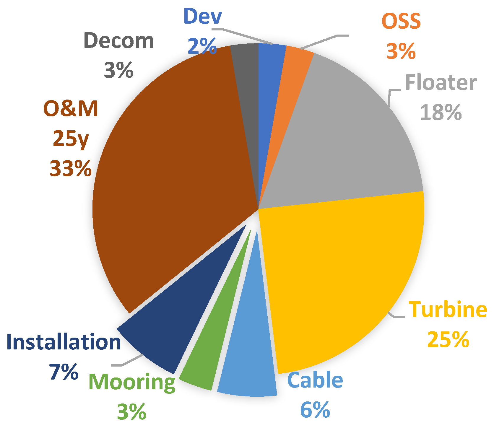
The biggest challenge facing the utility-scale adoption of FWT (Floating Wind Turbines) is their cost. While it is inevitable that the mooring, anchor, and dynamic cable will all increase the cost of FWT above that of its fixed-bottom counterparts, the elephant in the room is the O&M cost, which accounts for approximately 35% of the total project cost, according to the BVG Associates report [1].
Figure 1.
Floating Wind Farm cost items [1].
Figure 1.
Floating Wind Farm cost items [1].
Maintenance cost is so high for a very simple natural reason – the turbine or other parts can’t be repaired while they are heaving, swaying, and rolling on the ocean waves. The status quo is to tow the entire floater to a suitable port for maintenance, often in another country, which results in weeks of lost operational revenue.
The biggest challenge, however, is the disconnection of the floater from permanent moorings and dynamic cable before towing and re-connection after the maintenance, as shown by the only publicly available real-life study case, it takes 3 vessels (and much of their rent time wasted waiting for calmer sea) and almost 100 days to complete the whole cycle [2]. For a large-scale project, as many as 7 vessels are needed for a floater with just 3 mooring lines, at a time when there is a global shortage of installation vessels, particularly in East Asia [3]. Moreover, modern 15 MW turbines require a minimum of 6 and a maximum of 9 mooring lines in typhoon-prone East Asian seas [4,5,6].
This problem is so critical that discussing solutions for it takes up all the meeting time of industry conference participants. The managers try and choose a suitable maintenance port, forecast the weather window, and maintain a dedicated maintenance fleet shared by several projects. In this paper, a novel solution is presented that does not require towing back for most issues.
The concept of FishTug is simple – hold the floater firmly in place while a floating crane assists with maintenance. Let’s cite swapping a turbine blade as the most common heavy maintenance objective. The mooring system indeed prevents the floater from drifting away, but only in a certain range called the excursion range; any attempt to minimize it would cause the floater and moorings to succumb to unsustainable loads. However, the floating crane that comes to do the maintenance and the floater itself are both moving in 6 DOF (degrees of freedom) on the waves, preventing successful blade lifting at best and colliding with each other at worst.
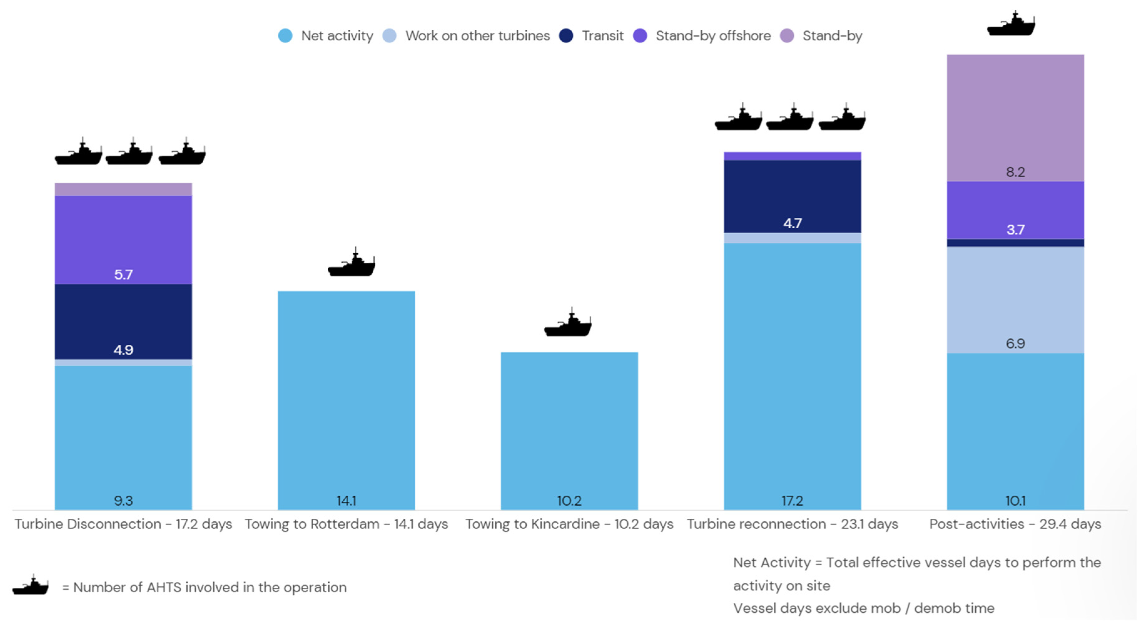
Figure 2.
Kincardine heavy maintenance: A 3-month operation mobilizing 3 AHTS for almost 100 vessel days. Activity breakdown from [2].
Figure 2.
Kincardine heavy maintenance: A 3-month operation mobilizing 3 AHTS for almost 100 vessel days. Activity breakdown from [2].
FishTug attaches itself to the floater hull with a magnet (for slender tubular structures, the magnet is swapped for a hand grip) and uses its 1-MW strong DP (dynamic positioning) system to compensate for the floater’s 1st and 2nd order wave, current, and wind–incurred movement. Depending on the weight of the floater and the environmental conditions, one FishTug may not be sufficient, so as many as needed can be attached to the floater and operate in sync, remotely controlled from a nearby crane or other vessel.
In this way, FishTug, together with a crane vessel, enables fast (1-3 days) on-site maintenance, offsetting its operation and capital cost with an overwhelming reduction in maintenance downtime (100+ days).
The best part – all the constituent technologies (Temporary Dynamic Positioning System, Heave Compensation System, Submarine ROV, Floating Crane, Gripper for Ocean Structures) are already well-established and tested, only their combination and area of application is novel, allowing for fast development and implementation.
Concept Design
FishTug is an advanced submarine ROV with a DP system. Its constituent systems are explained in this part, and the overall view is shown in Figure 3.
DP System
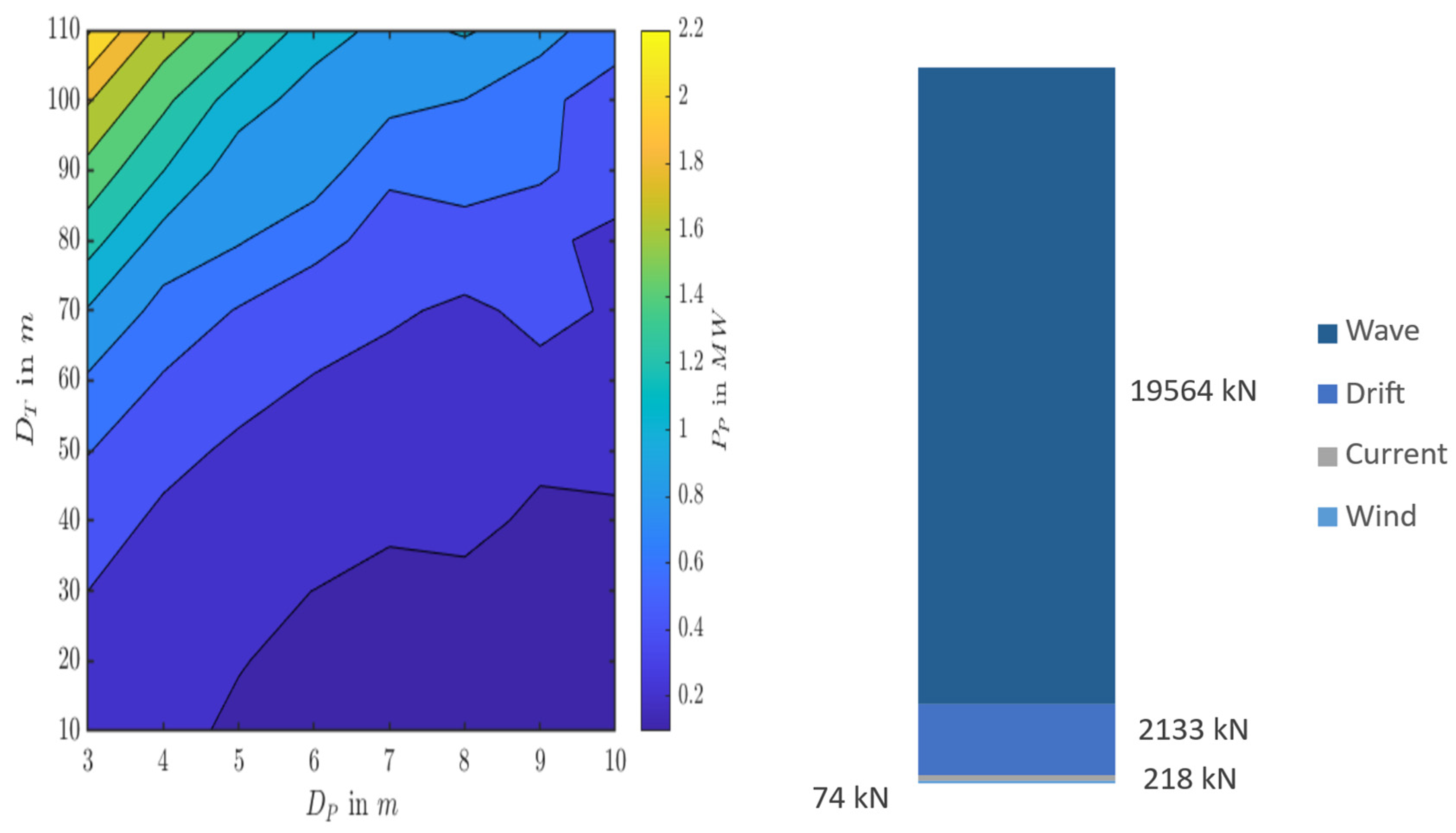
A traditional DP is a propeller that can rotate 360°, providing propulsion force in any direction to counteract environmental forces. Alwan et al. [7] studied the possibility of “mooring” a FWT with a DP system; they concluded that only three DP propellers are required to hold an example FWT floater in all, including severe, environmental conditions. The smaller the propeller diameter, the worse the efficiency, so they opted for a bigger one; however, a big propeller would require a very big ROV, so the smallest possible propeller is used – the efficiency is not critical as the FishTug will only operate for 1-3 days and not 25 years as in the study. Figure 4 shows that the smallest studied diameter was 3 m, and it would require a power range of 0.2-2.2 MW in different operation modes.
The DP system in the above paper was designed to handle 2nd order wave, current, and wind forces in all environmental conditions, while FishTug will handle 1st and 2nd order wave, current, and wind forces, but only in sea states with Hs lower than 3.5 m (standard for DP-assisted vessels, such as the floating crane). The approximate scale of different forces is illustrated in Figure 4. As this is only a concept design and the operating conditions are very different, we will assume a mean value of 1 MW as the required power for the 3 m propeller.
Tunnel type DP – 1 SKP (95, Taiwan Strait) (non-redundant, because several FishTugs will be used). Environmental load calculation according to ABS DP rules [8] 9.7.1-3.
Hull
The hull's primary design constraint is to support the turret holding the 3m DP system, and its function is to provide sufficient buoyancy to counteract all the weight. Additionally, a large space is occupied by buoyancy modules that the submarine requires; they will also serve as a heave compensation system. Hull's displacement is 123 t, and turret’s 46 t, totalling 170 t. The buoyancy modules total 36 t, they are placed in the middle of the hull, while equipment is close to the plating for easy maintenance access. The hull features legs for storage on the deck.
Grip
FishTug attaches itself to a floater’s flat surface using a flat magnetic grip; it could be swapped for a hand gripper if attachment to a tubular pipe is needed instead. The floater is still moving around and can hit FishTug until the very moment they are connected. To prevent impact damage, the grip’s piston can be pushed inside a piston cage inside the hull; a spring shock absorber or other damping system is used to lower the impact force. Two projectors facilitate the connection with lighting.
Motors
While en route to the floater, FishTug will utilize a small propulsion screw and a rudder at the back. They are powered by an electric motor in the back of the hull. A big motor inside the turret is powering the DP system, and 4 yaw motors rotate the turret, similar to a wind turbine’s yaw system.
Power
FishTug’s operations take a few days, so it needs to be powered by an umbilical power cable. If the cable fails, a large, advanced lithium-ion battery pack is required to operate a 1 MW propulsion system for 2 hours, including cooling and safety margins. With a specific energy of 250 Wh/kg, the mass would be approximately 10 t.
Control Unit
During most of its operation time, FishTug is connected to a floater and operates the DP system without an operator through the control unit. Manual control can be taken by a crane vessel-based operator if needed during attachment operation.
Mode of Operation
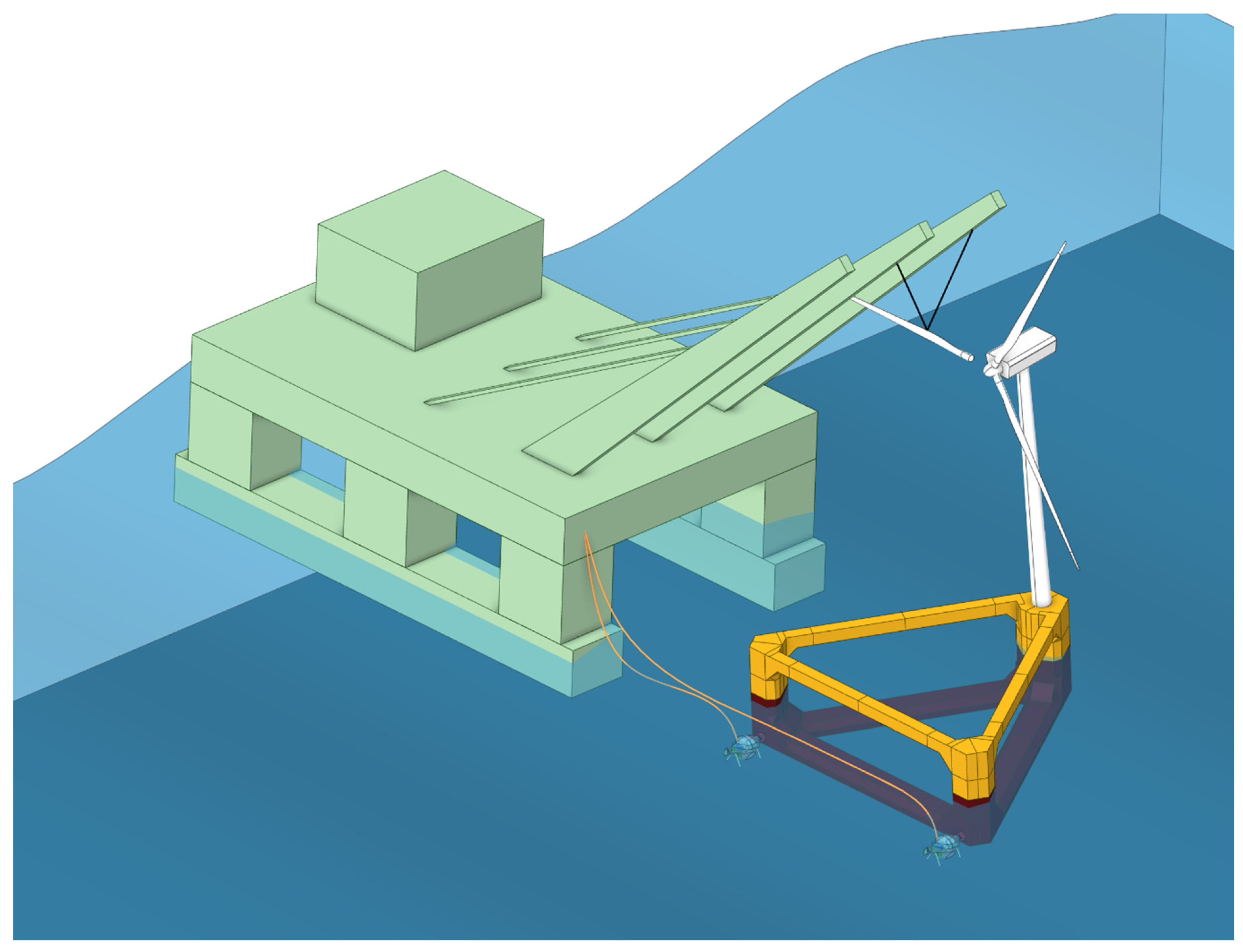
FishTug can perform a variety of support functions: replacing stabilizing side tugs during harbour tow-out operations, positioning the floater during mooring hook-up, etc. It could empower on-site turbine installation, as opposed to currently mainstread in-harbour installation, which is problematic due to harbor limitations [11,12]. The main purpose is to provide the floater with dynamic positioning during heavy maintenance, such as in Figure 5, when a floating crane vessel (equipped with DP) is performing a turbine blade replacement.
Carbon Footprint
Reducing carbon footprint is the goal of Wind Energy. While already quite clean in an industry, FishTug enables even more emissions reduction. The ships involved in the transportation and installation of FOWT components are currently all powered by combustible fuel. For a tow-to-shore real-life case in Figure 2, there is a total of 175 vessel days of work. As a rough estimate, considering 17.5 m³ of marine gasoil consumption per day, this yields 8,208 tonnes of CO₂ emissions solely from the vessel's fuel consumption during a single tow-to-shore maintenance operation.
In contrast, the total CO2 emissions from powering FishTug’s 2 MW electric DP system by a generator running 24/7 for 7 days are approximately 225 tonnes of CO2. Using 2 FishTugs and a floating crane (conservatively assumed 10x consumption), we get a total of 2700 tonnes of CO2, 3 times less than the tow-to-shore!
“Mother Nature is a self-taught engineer”Stewart Stafford
Inspiration
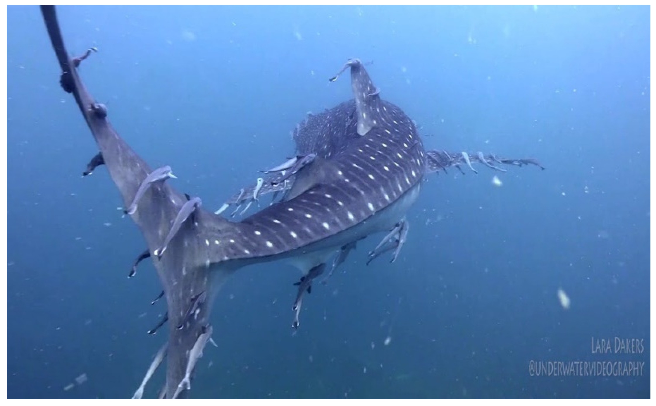
Remora is a fish that attaches itself to a shark for a time. It needs fast water flow to breathe, and traveling with a host allows it to do just that without expending any energy. While at it, it eats all the pesky parasites that plague the shark, helping it maintain good health – a symbiotic relationship. Just like in nature, FishTug attaches to a floater to help maintain it in good condition.
Figure 6.
Remoras on a shark. Picture courtesy of: Lara Dakers @underwatervideography.
References
- BVG Associates, Guide to a Floating Offshore Wind Farm. 2023, The Crown Estate and Crown Estate Scotland: Offshore Renewable Energy Catapult. Available from: https://guidetofloatingoffshorewind.com/wp-content/uploads/2023/06/BVGA-16444-Floating-Guide-r1.pdf.
- McLean, S., Lessons learned from heavy maintenance at the world’s first commercial floating wind farm, in spinergie. 2023. Available from: https://www.spinergie.com/blog/lessons-learned-from-heavy-maintenance-at-the-worlds-first-commercial-floating-wind-farm.
- Hasumi, T., et al., The number of AHTSs and CLVs required for installation of floating offshore wind farms with weather characteristics and installation strategies. Journal of Marine Science and Technology, 2025. [CrossRef]
- Ma, K.-T., et al., Wind Farm Design with 15MW Floating Offshore Wind Turbines in Typhoon Regions. Journal of Marine Science and Engineering, 2025(13(4)). [CrossRef]
- Ivanov, G., Y. Wu, and K.-T. Ma, Optimized mooring solutions for floating offshore wind turbines in harsh environments. Ocean Engineering, 2025. 340: p. 122289. [CrossRef]
- Ivanov, G., et al., Impact of tropical cyclones on mooring designs of floating offshore wind turbines. Ocean Engineering, 2025. 341: p. 122490. [CrossRef]
- Alwan, R., A. Babarit, and J.C. Gilloteaux, Investigation of a dynamically positioned floating offshore wind turbine concept. Journal of Physics: Conference Series, 2021. 2018(1): p. 012001. [CrossRef]
- Amercian Bureau of Shipping (ABS), Guide For Dynamic Positioning Systems, A.B.o. Shipping, Editor. 2018: Houston, Texas, USA. Available from: https://ww2.eagle.org/content/dam/eagle/rules-and-guides/archives/other/191_dpsguide1/DPS_Guide_e-May18.pdf.
- Hsu, I.-J., et al. Optimization of Semi-Submersible Hull Design for Floating Offshore Wind Turbines. in 41st International Conference on Offshore Mechanics and Arctic Engineering (OMAE 2022). 2022. Hamburg, Germany: American Society of Mechanical Engineers. [CrossRef]
- Ivanov, G., I.-J. Hsu, and K.-T. Ma, Design Considerations on Semi-Submersible Columns, Bracings and Pontoons for Floating Wind. Journal of Marine Science and Engineering, 2023. 11(9): p. 1663. [CrossRef]
- Ivanov, G. and K.-T. Ma, Floater Assembly and Turbine Integration Strategy for Floating Offshore Wind Energy: Considerations and Recommendations. Wind, 2024. 4(4): p. 376-394. [CrossRef]
- Crowle, A. and P. Thies, Floating offshore wind turbines port requirements for construction. Proceedings of the Institution of Mechanical Engineers, Part M: Journal of Engineering for the Maritime Environment, 2022. 236(4): p. 1047-1056. [CrossRef]
Figure 3.
Overview of the FishTug concept (Hull transparent).
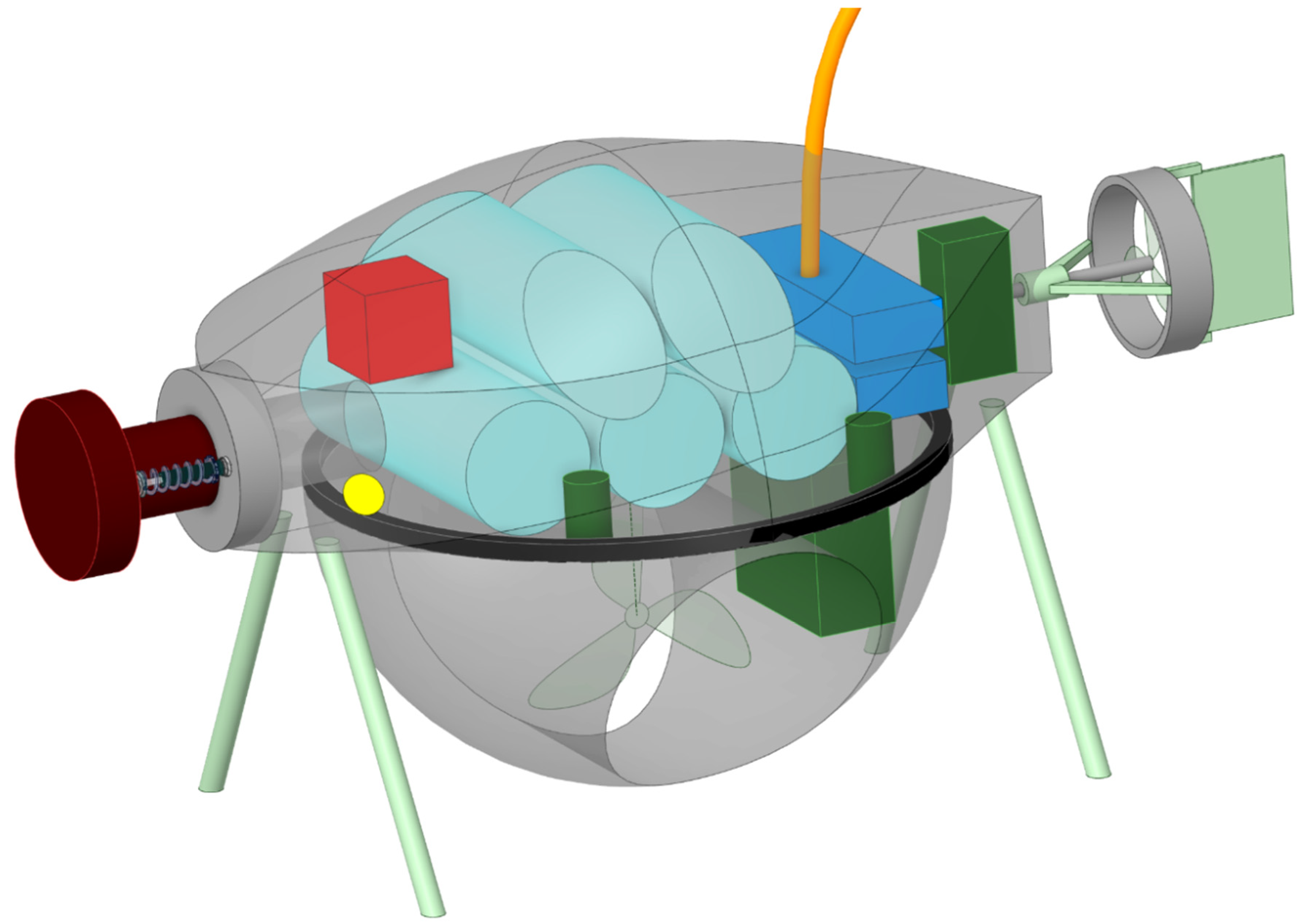
Figure 4.
Left: Relationship between DP propeller required power, its diameter, and wind turbine diameter (can be interpreted as different load). Courtesy of [7]. Right: 1st order (wave), 2nd order (drift), current, and wind forces, maximum forces acting on 15 MW TaidaFloat. Note that the current and wind max forces are negligible (they are important for mean loads). Source: Author’s.
Disclaimer/Publisher’s Note: The statements, opinions and data contained in all publications are solely those of the individual author(s) and contributor(s) and not of MDPI and/or the editor(s). MDPI and/or the editor(s) disclaim responsibility for any injury to people or property resulting from any ideas, methods, instructions or products referred to in the content. |
© 2025 by the authors. Licensee MDPI, Basel, Switzerland. This article is an open access article distributed under the terms and conditions of the Creative Commons Attribution (CC BY) license (http://creativecommons.org/licenses/by/4.0/).
Copyright: This open access article is published under a Creative Commons CC BY 4.0 license, which permit the free download, distribution, and reuse, provided that the author and preprint are cited in any reuse.


