Submitted:
02 October 2025
Posted:
17 October 2025
You are already at the latest version
Abstract
A non-pneumatic tyre (hereby referred to as “NPT”) is a tyre that is not supported by any internal air pressure. Hence, they tend to be more reliable than a conventional tyre supported by compressed air. They have a wide range of advantages mainly due to their run-flat properties and low rolling resistance. While pneumatic tyres are still preferred, it has displayed some disadvantages such as the necessity to maintain interior air pressure and the possibility to burst while driving. Recently, non-pneumatic tyres have been developed in the hope that they may replace conventional tyres one day. However, most of the research conducted is mainly based on spokes with a uniform degree. In this paper, we discuss the behaviour of a non-pneumatic tyre with a varying degree of honeycombed structured spokes. The density of spokes will decrease when approaching the surface of the tyre which is on contact with the road, and increases when approaching the centre hub of the wheel. The new design was modelled on Autodesk Inventor and analysed on Ansys Workbench to obtain results similar to what we expected. By altering the distance and shape between the spokes, it has displayed significant improvement over existing NPT’s showing less stress and deformation in the wheel.
Keywords:
non-pneumatic tyre
; finite element analysis
; honeycomb spokes
; workbench
; ANSYS
; Autodesk Inventor
; bicycles
Introduction
An NPT in this research paper is an airless tyre with varying degree of honeycombed structured spokes connected to wheel hub made out of an Aluminum Alloy. The spokes in itself are made of polyurethane which provides the tyre with high flexibility, thereby offering comfort, and high strength, thereby offering robustness and longevity. The shape of honeycomb plays a significant role in determining the type of force the structure can withstand. Umesh G C [1] says that spoke design with a honeycomb shape as a rhombus or a triangular cell offers a high modulus structural design whereas hexagonal structures are primarily used for high shear and axial loadings. Umesh G C [1] concludes by mentioning that the per spoke deformation in an NPT is far lesser than a conventional tyre, hence, NPT’s are very likely to replace Pneumatic tyres in the future. Car manufacturers have recently been under pressure from various organisations and governments to reduce C02 emissions. Reducing the weight of a vehicle dramatically helps in improving efficiency. It is commonly known that NPT tyres are significantly lighter than Pneumatic tyres.
Due to their unique spoke design, they can withstand higher weights. Nibin Jacob Mathew [2] states that the environmental benefit far outweighs the disadvantages of high upfront costs. Since NPT tyres are mainly made of composite materials in unique designs, they do not need to be replaced frequently compared to Pneumatic tyres. Even when they need to be replaced, the honeycombed structured spokes can be recycled to form new shapes. Nibin Jacob Mathew [2] also mentions that since they do not depend on compressed air, users would rarely have to worry about flat tyres. Vinay T V [4] concludes his research by saying that spokes with a higher cell angle magnitude show lower stresses. A higher cell angle would result in NPT’s that are comparatively more fatigue resistant. The spokes of an NPT continuously undergo tension and compression when under dynamic loading. Xiaochao Jin’s [3] research shows that the maximum stress on each spoke is lower compared to the traditional tyre. However, an NPT tyre can carry more weight in total compared to a Pneumatic tyre. The basis of today’s research paper will be based on static loading of an NPT tyre with varying degree of spokes. By not having a uniform distance between the spokes, we believe that an NPT tyre will be able to withstand more stresses and have a longer lifetime compared to NPT’s with uniform distant spokes. To prove this theory, we have developed a sample bicycle tyre on Inventor and placed it under static loading. The various design parameters, results, comparisons and conclusion obtained have been mentioned in the remaining section. We have compared our design of an NPT tyre to existing NPT designs in the market.
CAD Model
Design of a Secondary Hub
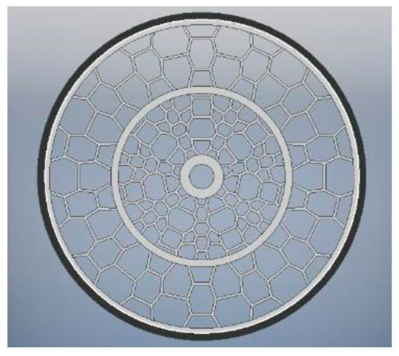
As mentioned earlier, our spokes have a varying degree of distances. Therefore, a secondary hub is developed between the rim and the primary/ centre hub (as shown in Figure 1) to act as a pivot point to house the various spokes. Our new model is a revolutionary new design that alters the stress and deformation experienced by the wheel. The new secondary hub is placed precisely in between the rim and the primary hub. By doing so, we can provide spokes that have equal heights but varying widths.
Design of Spoke Structures
While designing the model, we divided the whole structure into individual cells as displayed in Figure 2. Individual cells were then combined to form the entire tyre. The outer honeycombs are designed in a hexagonal manner so they may be able to withstand high shear and axial loadings. The inner honeycombs of our wheel combine two different shapes of octagons and pentagons.
The wall thickness of each hexagonal structure is 0.5cm.
INVENTOR Model
The figure above displays the final bicycle tyre model designed on Autodesk Inventor. The model is used in ANSYS for analytical experimentation purposes. We used ANSYS Workbench to compute the finite element analysis.
Figure 3.
CAD Design.
Geometrical Dimensions
Width of the wheel = 37mm
Outer Diameter of Tyre Tread = 672mm
Inner Diameter of Tyre Tread = 642mm
Outer Diameter of Rim = 642mm
Inner Diameter of Rim = 622mm
Inner Diameter of the Primary Hub = 50mm
Outer Diameter of the Primary Hub = 90mm
Inner Diameter of the Secondary Hub = 341mm
Outer Diameter of the Secondary Hub = 371mm
Finite Element Analysis
The NPT model was initially created on Autodesk Inventor. The model was then imported into ANSYS Workbench, which was used to solve the finite element model. Finite element analysis is a type of computer program that utilises finite element method to analyse a material and identify how applied forces will affect the material.
Figure 4.
Meshed Surface.
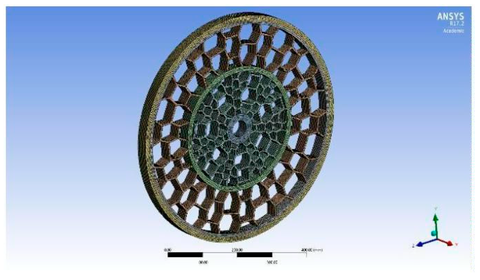
The figure above shows the meshed model of our NPT design. The parts of our model are consistently meshed. A rectangular mesh was utilised since all the components were symmetrical. The mesh relevance centre selected is coarse. However, the smoothing was set to high, and the element size was selected to be 5mm to attain more accurate results. In total, there are exactly 4218 elements and 263605 nodes.
Material of Honeycomb Structured Tyre
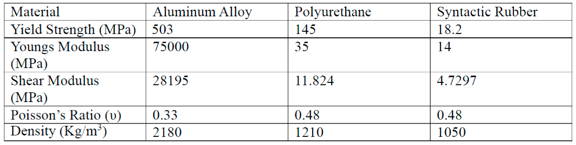
To achieve maximum durability and high comfort, a mixture of materials was used. The primary and secondary hubs are made of an aluminium alloy while the hexagonal structured spokes are made of polyurethane. The outer most surface is made of a Syntactic rubber to achieve maximum grip on the road. The reason for selecting these materials is that they can operate in a wide range of temperatures and hence can be used as all season tyres. Additionally, these materials combined offer high stiffness while offering high flexibility at the same time. The flexibility property aids in comfort while the stiffness helps in the durability of the tyre.

Table 1.
Material Properties.
 |
Boundary Conditions
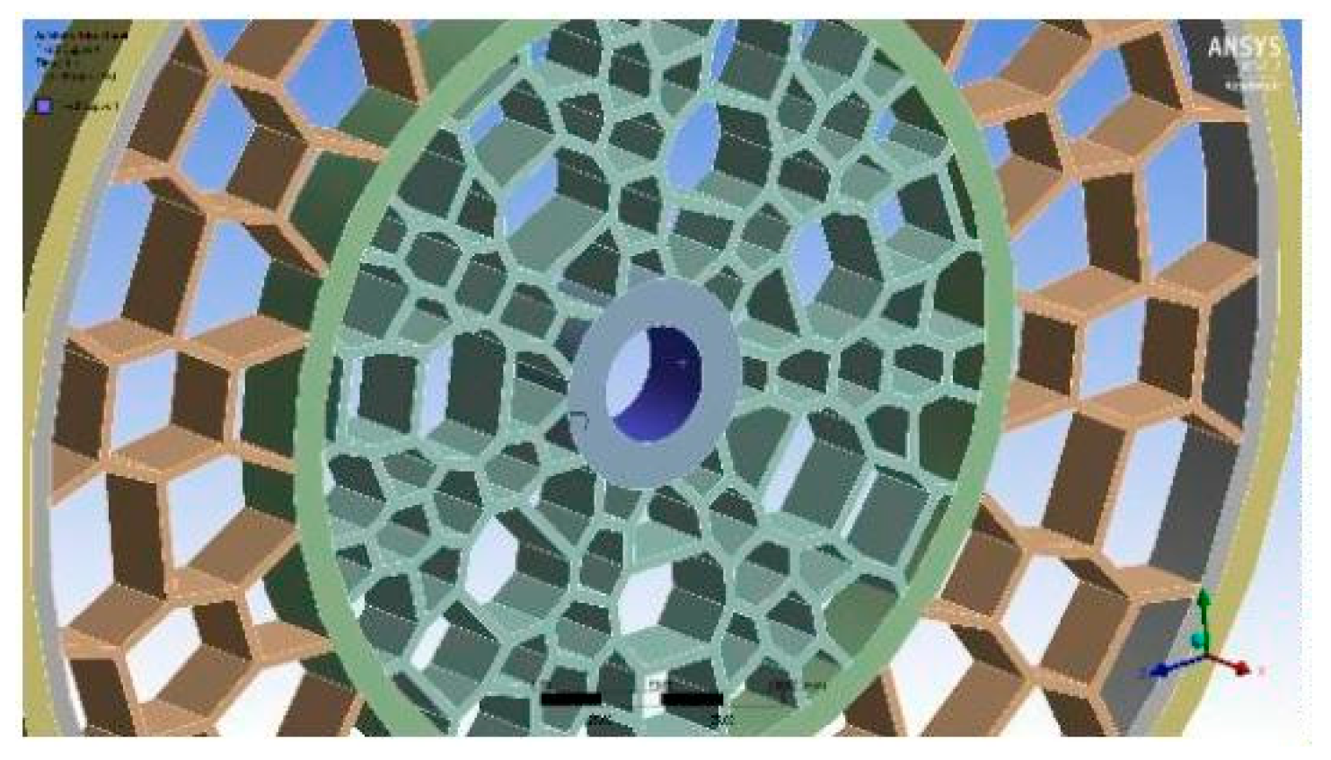
Boundary conditions were set depending on which areas would undergo zero displacements. The primary hub was set in such a way that it would not be able to undergo any displacement. The reason for this is because the primary hub acts as a support for the rest of the wheel which is attached to the bicycle. The figure above shows the constrained environments of the tyre. The inner part of the primary hub is blue indicating that the area has been constrained to restrict movement in all directions.
Figure 5.
Constrained Surfaces.
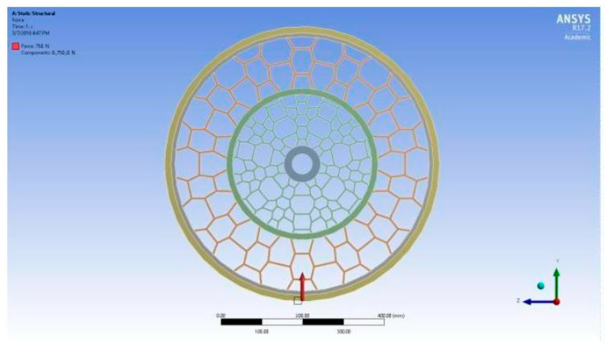
Applied Forces
Since the scope of our research is focused on static loading, forces were applied in the y-direction. The inner area of our NPT is constrained in all directions. The wheel is free to undergo deformation in all directions. Loads of 500N, 750N and 1000N is applied respectively vertically upward on the outer surface of the syntactic rubber. The red arrow on the figure above shows the direction of the force. Varying forces were applied to try to accommodate the various range of weights the wheel would have to withstand depending on the different people riding the bicycle.
Figure 6.
Forces Applied.
Assumptions
Some assumptions were made such as:
The inner/primary hub does not undergo any displacement.
The dimension of the wheels mentioned under “Geometric Dimensions” are actual
dimensions of a bicycle wheel.
The weight of the bicycle is ignored.
The maximum weight of the rider is assumed to be 100kg.
The secondary hub is precisely in between the rim and primary hub.
Results
Static analysis is conducted on the NPT based on the forces and constraints mentioned above.
Figure 7 above shows the equivalent maximum and minimum stresses experienced by the NPT when a 500N load is applied. The maximum stress experienced by the wheel is 1.06 MPa and the minimum stress experienced is 0.00038204 MPa. The maximum stress is marked on the picture with a red tag indicating the area close to the wheel hub to be undergoing maximum stress. The image on the right is a magnified picture.
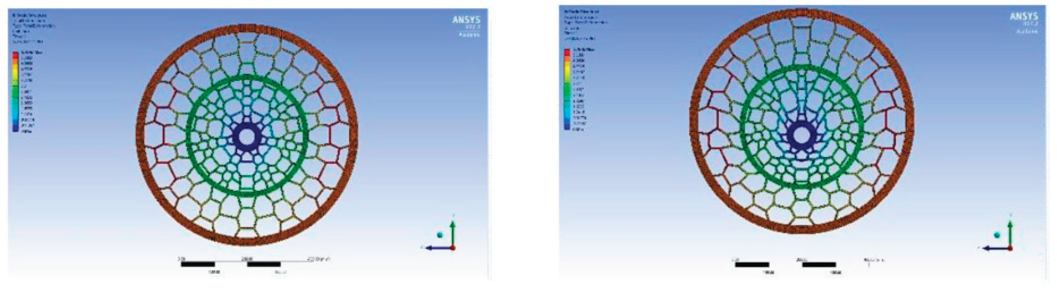
Figure 8 above shows the deformation the NPT undergoes when a 500N load is applied. The maximum deformation value is 2.8971 mm in the y-direction. The minimum deformation occurred in the other two directions, x and z-direction, with x-direction obtaining a max deformation value of 0.12887mm and a minimum deformation value of -0.12887mm. The z-direction experiences a maximum deformation of 0.54338mm while the minimum deformation is -0.53194mm. The figure on the right is a magnified image to indicate how the spokes deform under load. The red tag on the figure indicates the area of maximum deformation.
The figure above shows the stresses experienced by the modelled NPT when a 750N load is applied. The maximum stress experienced by the wheel is 1.5989 MPa. Umesh G C’s [1] NPT design undergoes 73.644MPa of maximum equivalent stress. The new design experiences significantly lower amounts of stress.
Figure 9.
Equivalent Stress under 750N.
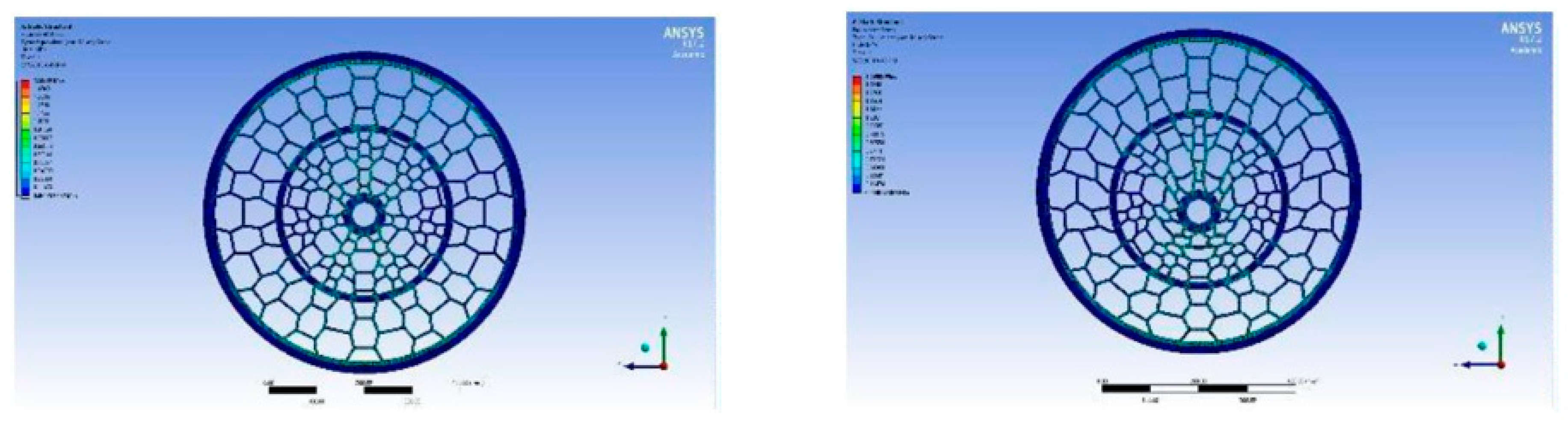
Figure 10 above shows us the deformation the NPT undergoes when a 750N load is applied. Themaximum deformation value is 4.3456 mm in the y-direction. The minimum deformation occurred in the other two directions, x and z-direction, with x-direction obtaining a maximum deformation value of 0.19331 mm. The z-direction experiences a maximum deformation of 81508 mm. The maximum deformation value in Umesh G C’s [1] model is 4.9839 mm, whichis still higher than the newly modelled NPT’s deformation value. The figure on the right is a magnified image, which shows us the actual deformations experienced by the wheel. The red colour on the side spokes of the wheel indicates that maximum deformation occurs in that area.
Figure 11 above shows the equivalent stresses experienced by the NPT when a 1000N load is applied. The maximum equivalent stress experienced by the wheel is 2.1319 MPa.
Figure 12 above shows us the deformation the NPT undergoes when a 1000N load is applied. The maximum deformation value is 5.7942 mm in the y-direction. The minimum deformation occurred in the other two directions, x and z-direction, with x-direction obtaining a max deformation value of 0.25775 mm and a minimum deformation value of -0.25775mm. The z- direction experiences a maximum deformation of 1.0868 mm while the minimum deformation is -1.0639 mm. As expected, the maximum deformation occurs in the side spokes of the wheel. The deformation structure is consistent with our previous figures with different loadings.
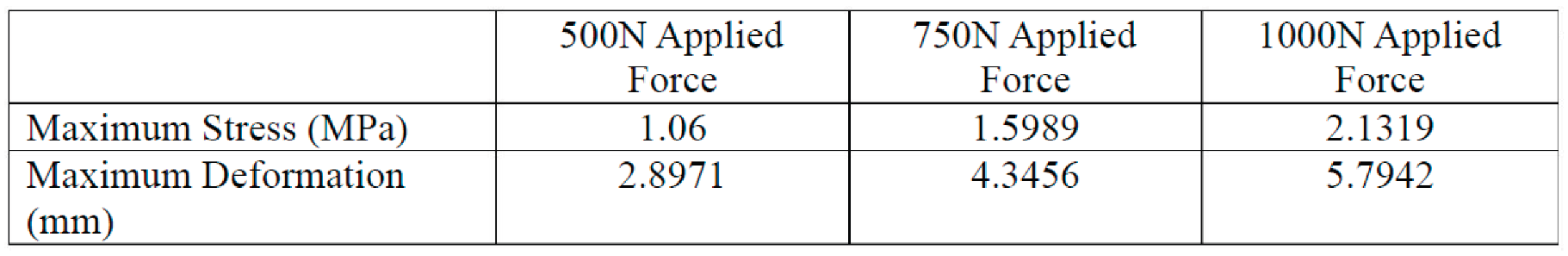
Summary of the Results Obtained
Table 2.
Results Summary.
 |
Conclusion
Since the materials and dimensions of the modelled NPT and Umesh G C [1] used are similar, the reduction in deformation and stress is highly likely because of the different design, where the density of the spokes increase when approaching the centre of the wheel. The increased density of spokes allows for more deformation, and therefore for more stress to be absorbed leading to less stress overall. There is a much-decreased chance of fractures occurring. It will also help smoothen out the ride and make it more comfortable as the forces will be absorbed by the wheel instead of the bike frame and its rider. Another reason for the significant reduction in stress in due to the extra material used. Since our new design utilises a secondary hub with additional spokes, it is expected that the maximum stress would decrease since there would be an additional number of spokes to absorb the load.
To summarise, hexagonal shaped honeycomb spokes with varying distances on the outer half and pentagonal and octagonal shaped honeycomb spokes with varying distances half of an NPT was studied. NPT’s are not supported by interior air pressure and have a lower rolling resistance. They have several advantages over a conventional tyre such as their run-flat properties. A non-uniform distant honeycomb is also better than traditional uniform distanced honeycombed since they can carry more load and deform less. These properties combined tend to offer both comfort and robustness.
In order enhance this research, it is recommendable to design a similar wheel with same properties and dimension. However, it should not contain a secondary hub, and the distances between the spokes should be of equal distance. When comparing such a model to our model NPT, it will give a precise difference in the stresses and deformation. It is also recommendable to build a model using the materials mentioned in this research so that it can be tested on a Universal Testing Machine. This would help us understand what will happen to the structure of the wheel if a load was applied to it for an extended period.
References
- Umesh G C, Amith Kumar S N, “Design and Analysis of Non-Pneumatic Tyre (NPT) WithHoneycomb Spokes Structure”, International Journal of Engineering Science and Computing,Vol. 6, Sept 2016, no. 9, pp. 2136-2140.
- Nibin Jacob Mathew, Dillip Kumar Sahoo, E. Mithun Chakravarthy, “DESIGN AND STATICANALYSIS OF AIRLESSTYRE TO REDUCE DEFORMATION”, Frontiers inAutomobile andMechanical Engineering, Vol. 197, no. 1, 2017, pp. 1–7.
- Xiaochao Jin, Cheng Hou, Xueling Fan, Yongle Sun, Jinan Lv, Chunsheng Lu, “Investigation on the static and dynamic behaviors of non-pneumatic tires with honeycomb spokes”, Composite Structures, 2017, pp. 27–35. [CrossRef]
- Vinay T V, Kuriakose J Marattukalam, Sachu Zachariah Varghese, Shibin Samuel, Sooraj Sreekumar, “Modeling and Analysis of Non-Pneumatic Tyres with Hexagonal Honeycomb Spokes”, International Journal on Recent Technologies in Mechanical and Electrical Engineering, Vol. 2, no. 3, 2015, pp. 19–24.
Figure 1.
Hubs, outer ring and rubber thread.
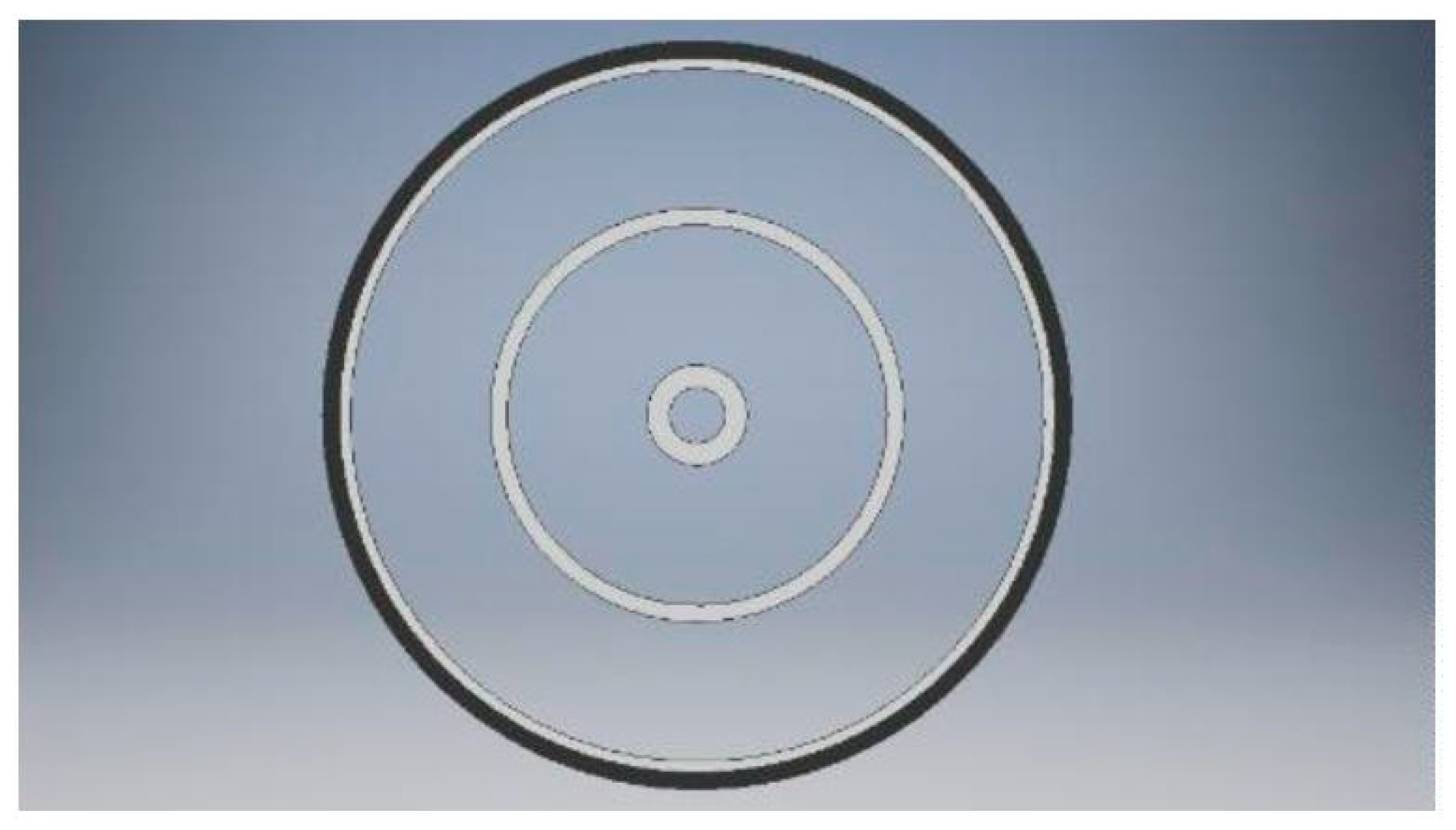
Figure 2.
Individual Spoke.
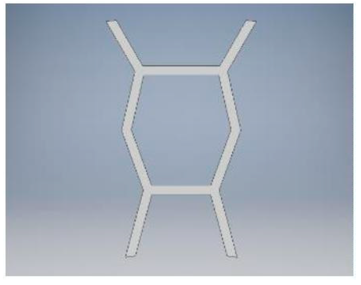
Figure 7.
Equivalent Stress under 500N.
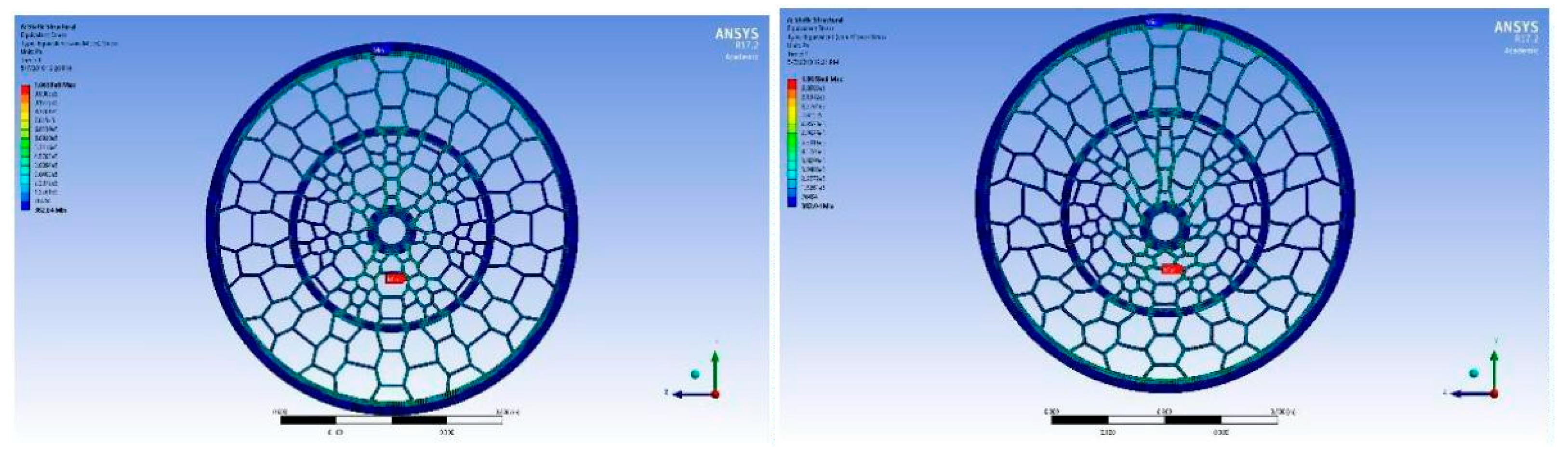
Figure 8.
Total Deformation under 500N.
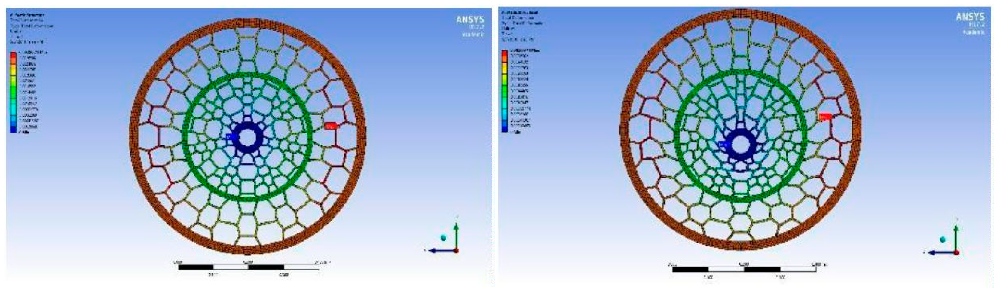
Figure 10.
Total Deformation under 750N.
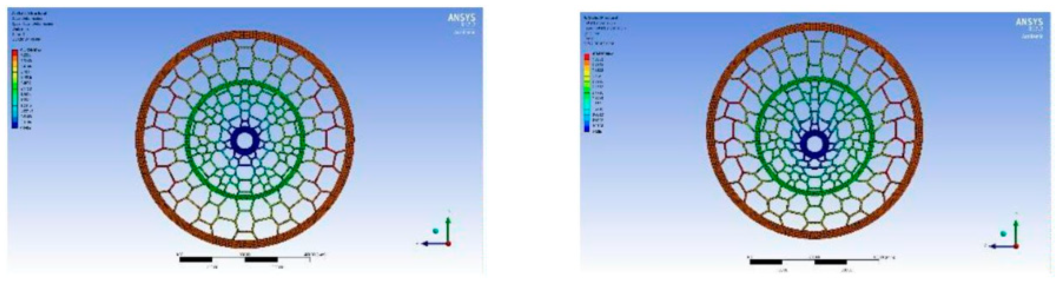
Figure 11.
Equivalent Stress under 1000N.
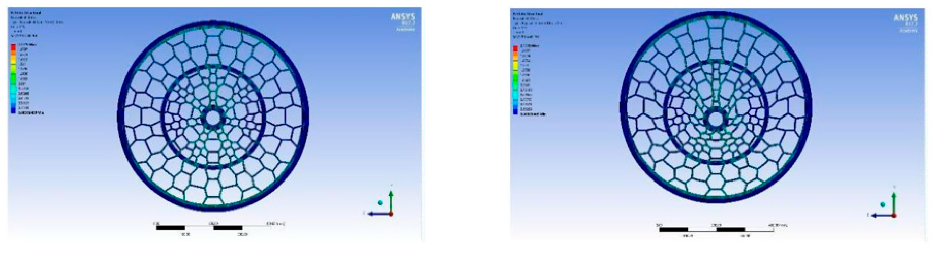
Figure 12.
Total Deformation under 1000N.
Disclaimer/Publisher’s Note: The statements, opinions and data contained in all publications are solely those of the individual author(s) and contributor(s) and not of MDPI and/or the editor(s). MDPI and/or the editor(s) disclaim responsibility for any injury to people or property resulting from any ideas, methods, instructions or products referred to in the content. |
© 2025 by the authors. Licensee MDPI, Basel, Switzerland. This article is an open access article distributed under the terms and conditions of the Creative Commons Attribution (CC BY) license (http://creativecommons.org/licenses/by/4.0/).
Copyright: This open access article is published under a Creative Commons CC BY 4.0 license, which permit the free download, distribution, and reuse, provided that the author and preprint are cited in any reuse.


