
Submitted:
21 August 2024
Posted:
21 August 2024
You are already at the latest version
Abstract
According to the honeycomb structure, the preliminary design of bionic wheel hub for finite element analysis, in the working condition of a wheel by the force is through the spokes pointing to the center, the working condition of two wheel by the force is through the two spokes pointing to the center, and the ordinary wheel stress and displacement value results compared, observed the maximum stress value appears in the connection between the center of the wheel and the spokes, and predict the fatigue life of the preliminary design of bionic wheel. Using finite element analysis and response surface optimization analysis method for numerical simulation, through two optimization results show that, in the use of response surface analysis model optimization, the optimized bionic wheel maximum stress is 109.34MPa, compared with the ordinary wheel maximum stress 119.77MPa, the maximum stress reduced by 8.7%. The mass of the ordinary wheel is 34.02Kg, using the response surface optimization method, the optimized wheel mass is 29.89Kg, the mass reduced by 12.13%. The optimized wheel fatigue analysis, in the stress of 109.34MPa, load loading times at least 4.217e+005, in the position at the junction with the half shaft. In line with the national standard GB/T 5334-2021[16] for commercial vehicle wheel fatigue life requirements.
Keywords:
finite element analysis
; response surface optimization design
; bionic design
; fatigue life prediction
1. Introduction
The wheel hub is a part of the automobile tire that plays the role of support, steering, driving and braking.The design of wheel hub needs to consider its performance, safety, comfort and match with the overall vehicle.The wheel hub structure mainly includes the rim and the spoke, the rim is used to install, support and fix the tire, and the spoke is connected to the rim and the wheel core to withstand various loads.wheel hub need to be designed to ensure stability and reliability in all driving conditions [1,4].Bionics is an interdisciplinary discipline that designs artificial systems and products by studying the structure and function of living organisms.In wheel hub design, bionics can provide inspiration to help designers create a wheel hub structure that meets both functional requirements and aesthetics[5,6].
The honeycomb structure in nature primarily experiences axial forces. Through continuous evolution, the internal stress and deformation of the honeycomb structure remain minimal when subjected to axial loads, thereby ensuring the safety of the eggs within the honeycomb[7].Honeycomb structures are commonly used for their lightweight and high-strength properties, making them suitable for typical working conditions similar to those experienced by wheel hubs. The stress characteristics of honeycomb structures closely resemble those of wheel hubs in such conditions.Huang Rui[8] et al. divided bionic design into two thinking processes of "top-down" and "bottom-up" from the perspective of bionic design, extracted the morphological characteristics of biological prototypes, and used the extracted results to complete the algorithm shape generation in the logic algorithm of parametric design. Finally, the feasibility of the scheme was verified through finite element analysis.Chen Tingting[9]et al. used the typical lightweight high-strength arachanthus siliceous shell structure as the bionic template and adopted the response surface method to optimize and design the optimal structure scheme of the bionic hub. Compared with the pre-optimization, the overall structure of the optimized structure was reduced by 8.4%, and the spoke weight was reduced by 25.6%. Compared with the Workbench response surface method, the prediction accuracy of the maximum equivalent stress of the structure using BP neural network is improved by 56.97%.In this paper, the honeycomb structure bionic design of wheel hub is carried out by numerical simulation method, and the static analysis and bending fatigue life prediction are carried out.
2. Static Analysis of Bionic Wheel Hub
Finite Element Analysis (FEA) is a numerical calculation method used in engineering and physics to simulate and analyze the behavior of complex objects under given conditions[10]. In wheel hub design, finite element analysis is particularly important, it can predict the performance of wheel hub in actual use, such as the strength and fatigue life in this paper, so as to ensure the safety and reliability of wheel hub [11,14].
2.1. Establishment of Finite Element Model
In this paper, a new bionic lightweight wheel hub is designed according to the honeycomb structure. The honeycomb structure is shown in Figure 1.(a). This paper makes reference to a 19-inch wheel hub to design and optimize the new bionic wheel hub, as shown in the following figure. According to the stress distribution in the bending condition of the wheel hub, the structure of the wheel hub is optimized and the bionic wheel hub is obtained as shown in the Figure 1.(b)-(c). For comparison, Figure 1.(b) is the ordinary wheel hub, Figure 1.(c) is the honeycomb structure wheel hub.
The wheel hub material is A356 aluminum alloy with three element alloy. The physical properties are shown in Table 1, and the strength meets the design requirements of wheel hub.Because the tire will involve nonlinear problems in the finite element analysis, it is only necessary to analyze the wheel hub model, simplify the model to improve the mesh quality, and ensure the authenticity and accuracy of the simulation calculation [15].
The minimum fatigue cycle number is obtained by numerical simulation by applying a rotating bending moment to the wheel hub which is fixed. In Table 2, according to GB/T 5334-2005 "Passenger Car Wheel Performance requirements and test methods", the number of cycles of bending fatigue test is required.The requirements and test methods of passenger car wheel performance are to ensure the safety and comfort of the vehicle under various driving conditions, while wheel fatigue analysis is to evaluate the performance of the wheel in long-term use, and provide a basis for the design and improvement of the wheel. These requirements and methods are interrelated, and together constitute a complete performance evaluation system of passenger car wheels from design to use [17,19].
2.2. Load Calculation under Bending Conditions
The load calculation of wheel hub under bending conditions [20] includes the calculation of shaft end load and bolt preload. Formulas (1) - (2) are the calculation of shaft end load.
M: bending moment(N.m), L( moment arm)=0.7m, μ(The coefficient of friction between the tire and the road)=0.7, R: Static load radius of tyres(m),d: Deflection of the hub(m),Fv: rated load(N), S: strengthen factor(Optimization coefficien).
Shaft End Loads,
L:( moment arm)=0.7m,F=6311.7N.F is the load at the end of the wheel hub shaft and the final calculation is 6311.7N.In the calculation of bolt preload under bending conditions [21], the wheel hub is fixed by connecting the bolt to the loading shaft during the experiment.Bolts with torque up to 150N.mde thread M14×1.5 were selected for the experiment, the bolt preload can be obtained by the following formula (3) - (7) ,
T1 is the ordinary thread moment,
FQ is the bolt load of axial,
d2 is the thread Middle Diameter,
λ is the angle of thread,
is the thread angle of equivalent friction,
In the above formula, f ( the friction coefficient of nut bearing surface)=0.3, d is the large diameter of the bolt, d2 is the pitch diameter, n(number of threads)=1, the pitch=1.5, the common thread has a bevel Angle of 30°, T1 is the bolt torque, the calculation result of FQ=27708N.
The bending stress of wheel hub in the process of driving is an instantaneous dynamic load [22], which is caused by road surface fluctuation during vehicle driving, friction between tire and road surface and other dynamic load sources.In the process of static analysis, these dynamic loads need to be converted into static loads [23] in order to facilitate accurate calculation by using static equations.The theoretical basis of converting dynamic load to static load is to ensure the accuracy of analysis model and the feasibility of calculation.
The essential difference between dynamic load and static load lies in the duration of load action and load characteristics.Dynamic loads are usually instantaneous and change over time, while static loads are assumed to be constant and remain constant in the analysis. When performing static analysis, it is necessary to convert the dynamic load to the static load, because in static analysis, we assume that the load is constant, so that the statics equation can be applied to the calculation.
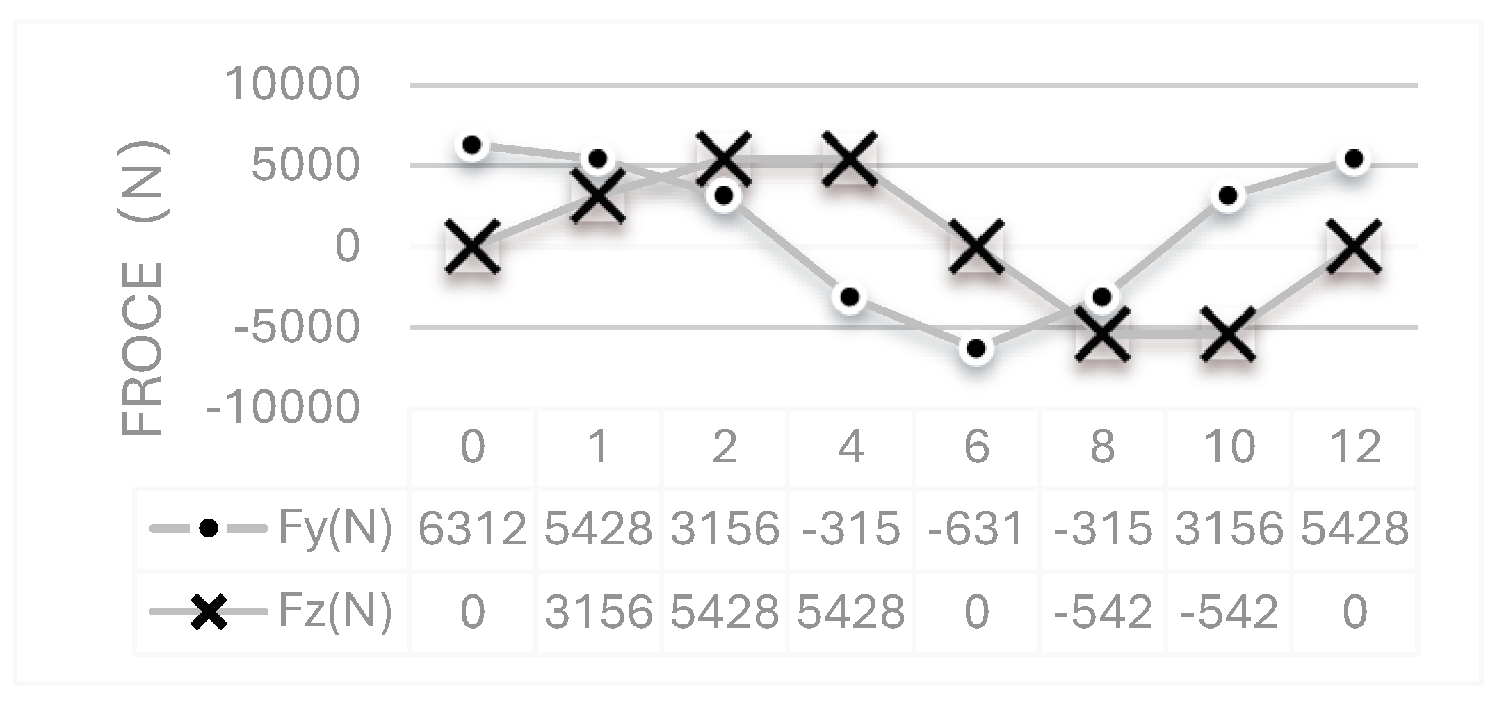
The end of the loading shaft is subjected to a bending moment, which is equivalent to the load at the end of the wheel hub shaft. The axial load is decomposed into the component forces in Z direction and Y direction. As shown in Figure 2.2, the paper sets 12 load sequences to simulate a complete loading process of wheel hub, with an interval of 30° as a calculation.
Figure 2.1.
wheel hub stress diagram.
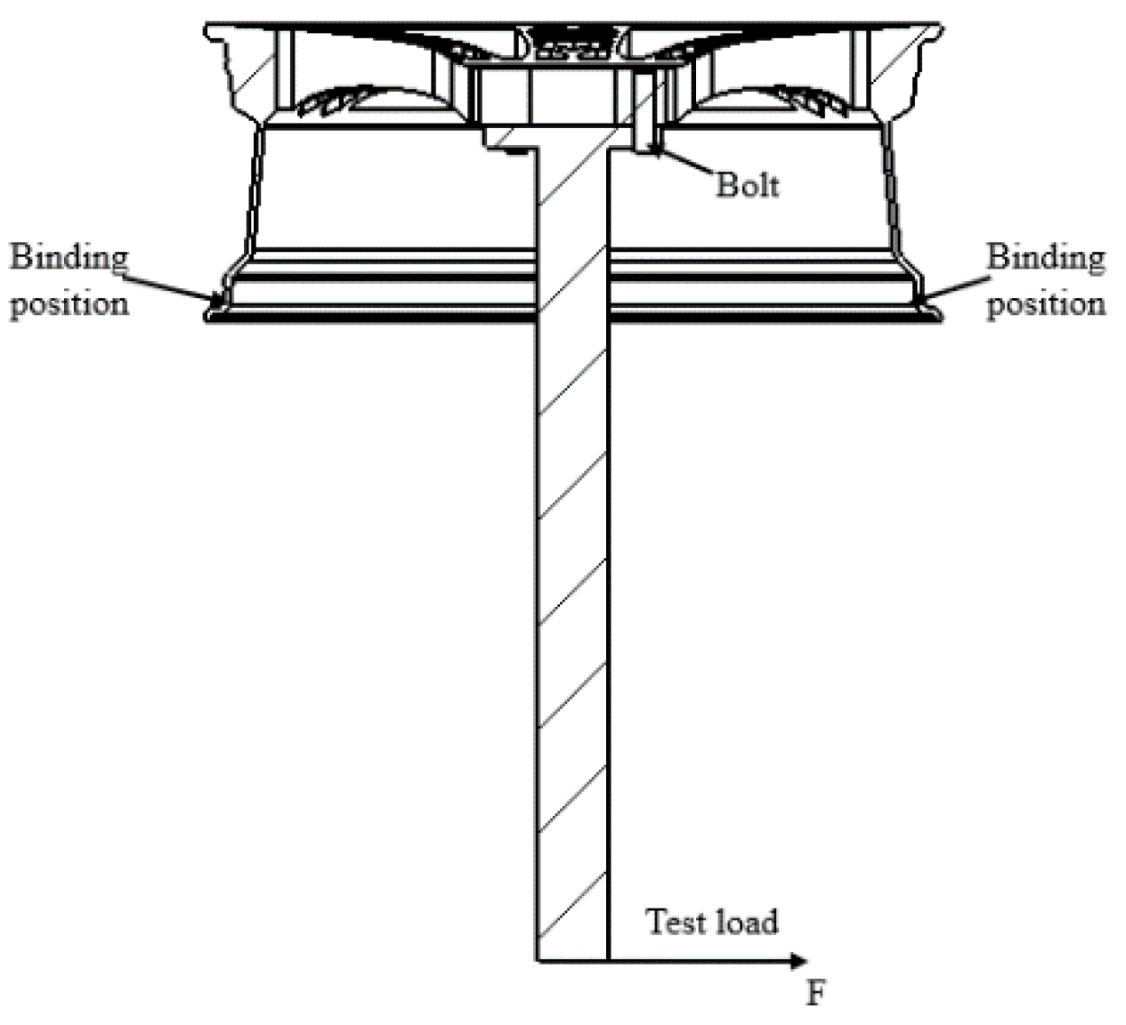
Figure 2.2.
12 load sequence values.
2.3. Stress Comparison between Bionic Wheel of Honeycomb Structure and Ordinary Wheel Hub
According to the special symmetrical structure of wheel hub, the following two working conditions are selected to compare the stress results. The first working condition is that the force on the wheel hub is directed towards the center of the circle through the spoke of the wheel, and the second working condition is that the force on the wheel hub is directed towards the center of the circle through the two spoke [24]. Under condition 1 (the force on the wheel hub is directed through the spoke towards the center of the circle), the stress may be concentrated at the junction of the spoke and rim, while under condition 2 (the force on the wheel hub is directed through the spoke towards the center of the circle), the location of the stress concentration may be different. These stress concentration areas are the possible locations of fatigue failure, so special attention should be paid to the structural strength and fatigue life of these areas in the design of wheel hub.
The finite element analysis results of bionic wheel of honeycomb structure and ordinary wheel hub under two working conditions are shown in Figure 3.
Figure 3.1.
stress nephogram and displacement of ordinary wheel hub under working conditions.
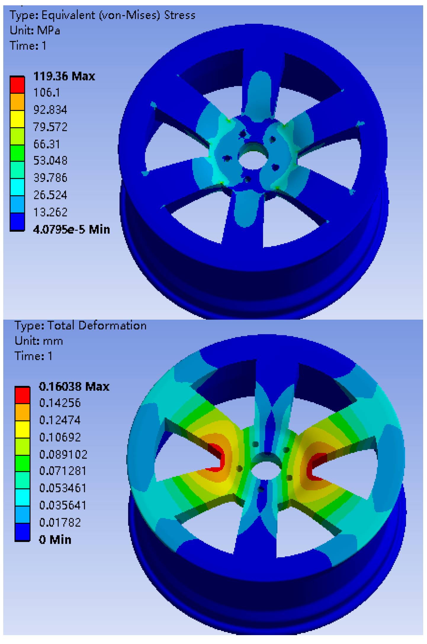
Figure 3.2.
stress nephogram and displacement of ordinary wheel hub under working condition 2.
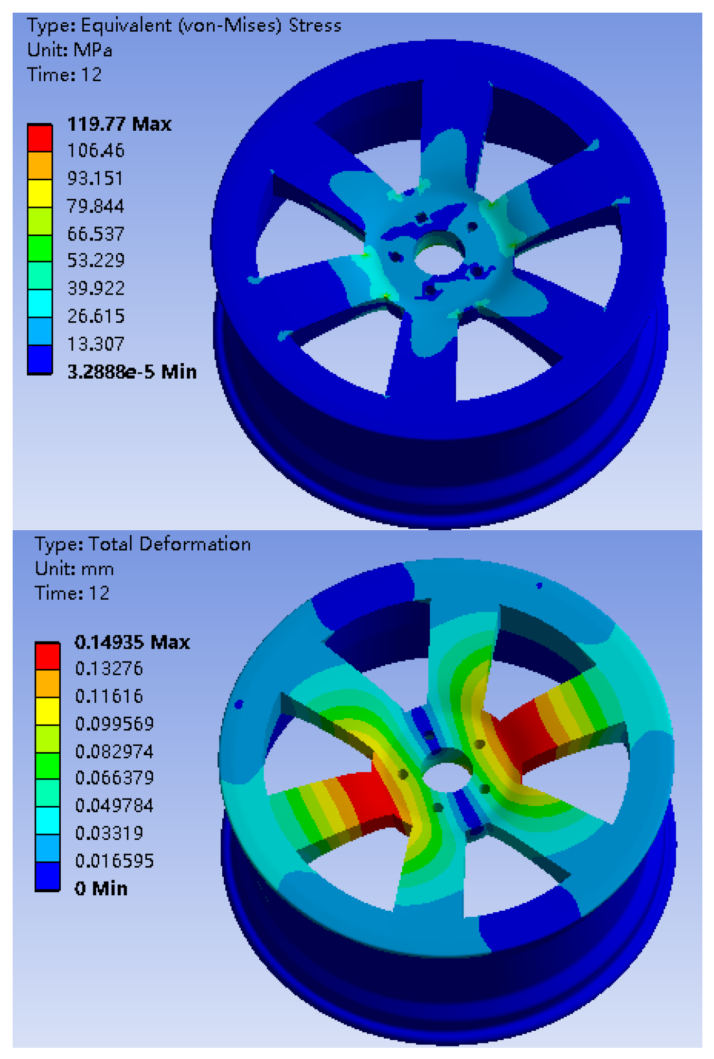
Figure 3.3.
Fatigue life analysis results of ordinary wheel hub.
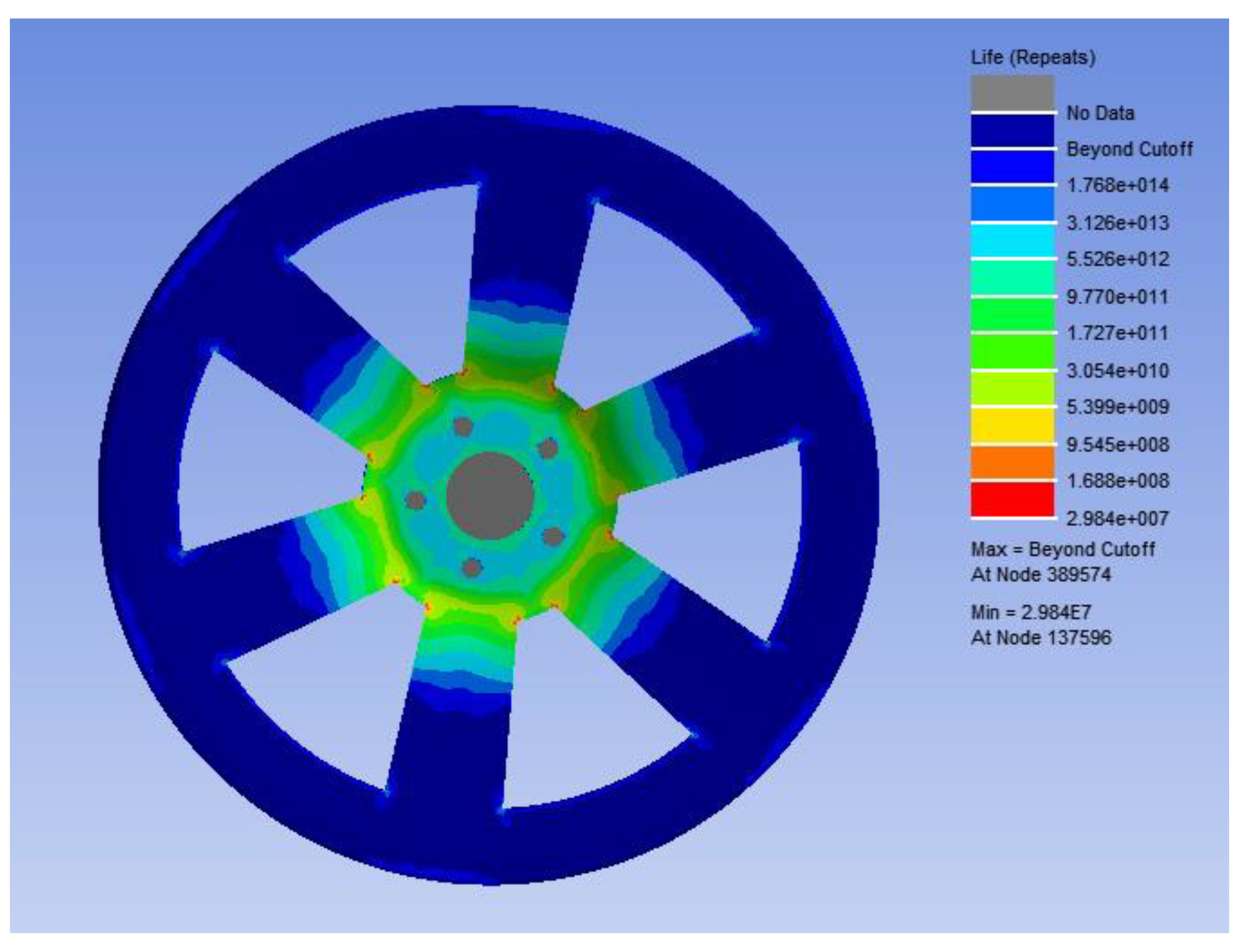
Figure 4.1.
stress nephogram and displacement of bionic wheel with honeycomb structure under working condition 1.
Figure 4.1.
stress nephogram and displacement of bionic wheel with honeycomb structure under working condition 1.
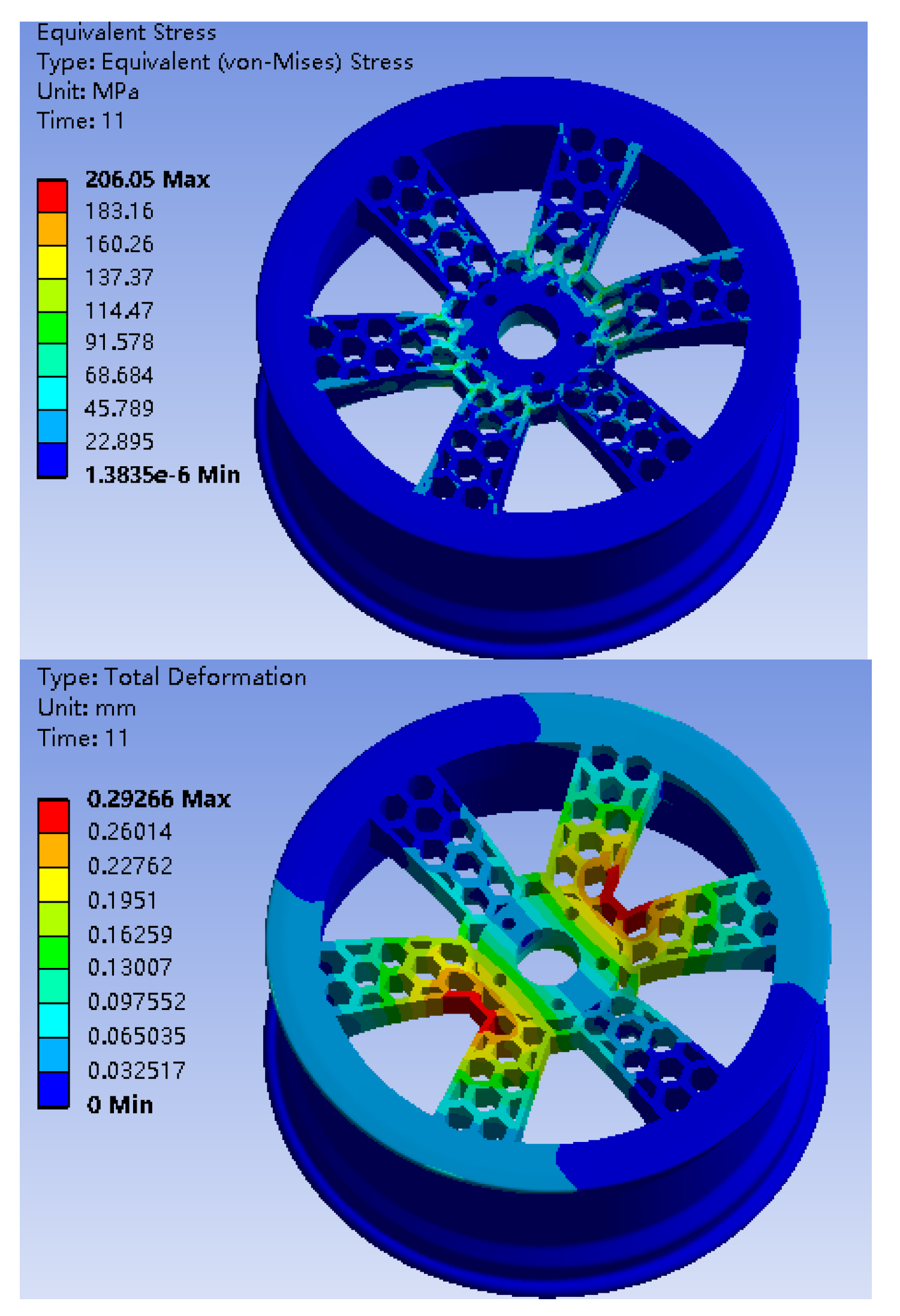
Figure 4.2.
stress nephogram and displacement of bionic wheel with honeycomb structure under working condition 2.
Figure 4.2.
stress nephogram and displacement of bionic wheel with honeycomb structure under working condition 2.
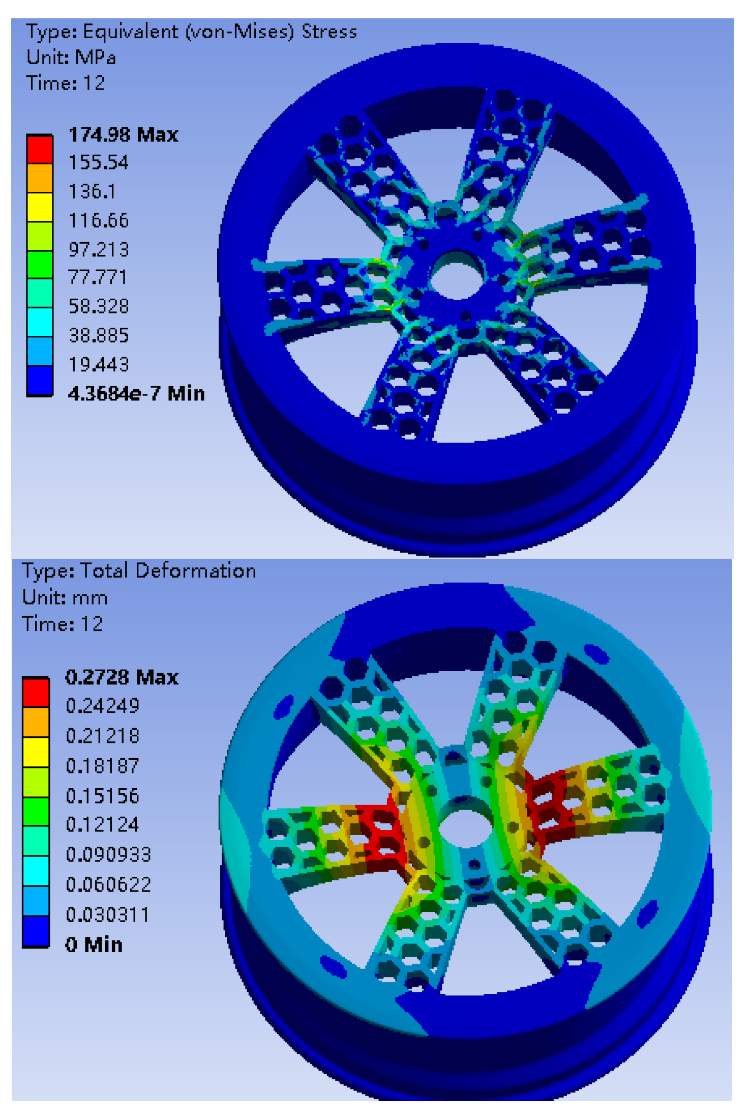
Figure 4.3.
Fatigue life analysis results of bionic wheel with honeycomb structure.
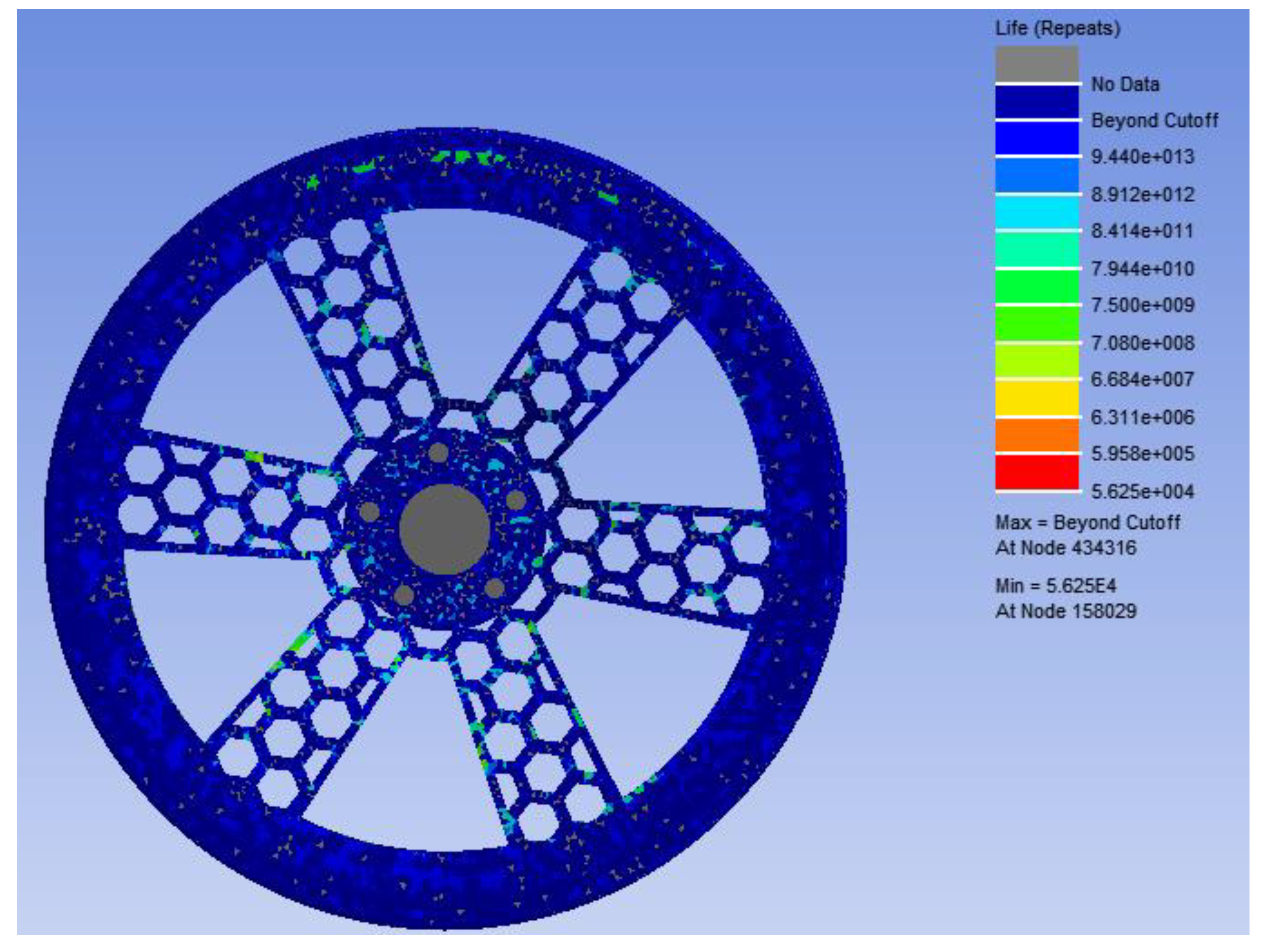
Under two different working conditions, the maximum stress of the preliminary designed bionic hub with honeycomb structure is near the center of the spoke. As shown in Table 3, the mass of the bionic wheel with honeycomb structure is reduced by 4.29Kg compared with the ordinary wheel hub, of which the spoke position is reduced by about 30%, however, the maximum stress increases under the same working condition. Although the wheel hub mass is reduced to some extent, the stress increases greatly and the wheel hub fatigue life decreases too much, which does not meet the goal of wheel hub optimization [25].
3. Bionic Hub Structure Optimization Design of Honeycomb Structure
The main function of the ring reinforcing bar in the position of wheel hub stress concentration is to disperse the stress and reduce the possibility of fatigue cracks in the wheel hub under repeated load. Reinforcement can be regarded as a local reinforcement measure, which plays a supporting role in the structure of the wheel hub, reduces the stress concentration caused by bending, and thus extends the fatigue life of the wheel hub.
In order to meet the requirement of the number of bending fatigue test cycles of wheel hub, a ring reinforcement was added to the stress concentration position of wheel hub. The optimized model is shown in Figure 5. On the basis of ensuring strength and fatigue life, lightweight design of wheel hub structure is carried out as far as possible. The response surface optimization method [26] was adopted to optimize the design of wheel hub middle ring stiffeners.
3.1. Response Surface Optimization Design of Bionic Wheel Hub with Honeycomb Structure
Response surface optimization (RSM) is a mathematical method for experimental design and parameter optimization. By establishing the response surface, the parameter space can be explored effectively to find the parameter combination that makes the specific performance index reach the optimal value. This approach is particularly useful in wheel hub design because it can help designers evaluate multiple design options within a limited number of experiments and determine which parameters are most critical to wheel hub performance [27,28].
In the design, five parameters with relatively low processing difficulty were initially selected. As shown in Figure 6, the five parameters were thickness (X1) of the ring stiffener, distance (X2) from the stiffener to the flange surface, thickness (X3) of the spoke honeycomb wall, thickness (X4) of the weight reducing hole and diameter (X5) of the spoke honeycomb hole.
The design uses dx response surface optimization module to optimize the wheel hub structure. As shown in the figure above, 5 main size parameters are defined as optimization parameters, with wheel hub stress and wheel hub mass as target parameters. As shown in Table 4, the variation ranges of the five parameters are defined.
3.1.1. Grey Correlation Degree Analysis of Five Parameters with Wheel Hub Stress and Quality.
“Grey correlation analysis “[13] is a multi-factor statistical analysis method. This method can identify whether there is a certain degree of correlation between variables by analyzing the grey correlation degree of data series [29,30]. In wheel hub design, this method can help to analyze how different parameters of wheel hub affect vehicle performance. In a grey system, the relative strength of wheel hub stress and mass affected by five target parameters is obtained.
As shown in Figure 7, the correlation coefficients between the five parameter pairs and the wheel hub stress correspond to 0.5559, 0.5780, 0.5582, 0.6217, and 0.6692, respectively. The analysis results show that X2, X4,X5 have strong gray correlation to the wheel hub stress. As shown in Figure 8, the correlation coefficients between the five parameter pairs and wheel hub quality correspond to 0.6926,.5950, 0.6289, 0.7725, 0.6537, respectively. The analysis results show that X1, X4, X5 have strong gray correlation with wheel hub quality.
According to the linear regression model, formula (8) is the linear regression equation of wheel hub stress and five parameters, and formula (9) is the linear regression equation of wheel hub mass and five parameters. As shown in Figure 9, the predicted and actual values are distributed on both sides of the fitting line, which conforms to linear regression fitting.
The first three parameters of grey relational degree were determined by grey relational degree analysis as distance from stiffener to flange surface X2, thickness of weight reducing hole X4 and diameter of spoke honeycomb hole X5. As shown in Figure 10, the results show that when the two parameters change at the same time [31], there is a point where the stress value is the smallest, and the value of the parameter corresponding to this point is designed, X2=110.5mm,X4=17.7mm,X5=118.1mm, the bionic hub with optimized honeycomb structure is designed and the simulation results are analyzed.
3. Results
The stress nephogram and displacement of the bionic wheel of the optimized honeycomb structure in working condition 1 are shown in Figure 11.1. The maximum stress occurs in working condition 1, with the maximum stress being 106.59MPa and the maximum displacement being 0.22mm. In the second working condition, as shown in Figure 11.2, the maximum stress of the bionic wheel of the optimized honeycomb structure is 99.144MPa and the maximum displacement is 0.22mm.
As shown in Table 4, the mass of the bionic hub of the optimized honeycomb structure obtained by finite element analysis is 31.17Kg. Compared with the result of the finite element analysis, the response surface optimization analysis results show that the mass is 29.89Kg, the error is 4.2%, and the maximum stress is 109.34MPa, the error is 2.5%, which meets the error requirements of the optimization model.

Table 5.
Comparison of analysis results of finite element analysis optimization and response surface optimization.
Table 5.
Comparison of analysis results of finite element analysis optimization and response surface optimization.
| Finite element analysis | Response surface optimization design | error | |
|---|---|---|---|
| Mass(Kg) | 31.17 | 29.89 | 4.2% |
| stress(MPa) | 106.59 | 109.34 | 2.5% |
Conclusions
In this study, the wheel hub was optimized by two different optimization methods, aiming at improving the fatigue life of wheel hub and reducing the quality. The optimization results show that the maximum stress is reduced by 8.7% and the wheel hub mass is reduced by 12.13% under the response surface optimization analysis method. In addition, the bending fatigue life of the optimized honeycomb bionic wheel hub is predicted. The result shows that under the stress of 109.34MPa, the load times are at least 4.217e+005, which meets the minimum cycle times required by the national standard for wheel hub bending fatigue experiment.
- (1)
- Two optimization results show that the maximum stress under the response surface optimization analysis method is 109.34MPa, which is 8.7% lower than the maximum stress of ordinary wheel hub of 119.77MPa.This change shows the effectiveness of optimization in alleviating wheel hub stress.
- (2)
- The mass of ordinary wheel hub is 34.02Kg, and the mass of wheel hub after optimization is 29.89Kg by response surface optimization method, which is reduced by 12.13%. The lightweight wheel hub not only improve the fuel economy of the vehicle, but also improve the handling performance of the vehicle.
- (3)
- The bending fatigue life of the bionic wheel of the optimized honeycomb structure is predicted. Under the stress of 109.34MPa, the load times will be at least 4.217e+005, and the position is at the connection with the half-shaft. It is higher than the design requirements of the strengthening coefficient 1.6, and meets the requirements of the minimum cycle number of bending fatigue test of wheel hub in GB/T 5334-2021[4].
In summary, through the optimization of honeycomb structure, the maximum stress of wheel hub is significantly reduced, the quality is also reduced, and the bending fatigue life is guaranteed to meet the national standard. Such optimization results not only prove the effectiveness of the optimization method, but also provide strong support for the performance improvement of wheel hub.
Data Availability Statement
We encourage all authors of articles published in MDPI journals to share their research data. In this section, please provide details regarding where data supporting reported results can be found, including links to publicly archived datasets analyzed or generated during the study. Where no new data were created, or where data is unavailable due to privacy or ethical restrictions, a statement is still required. Suggested Data Availability Statements are available in section “MDPI Research Data Policies" at https://www.mdpi.com/ethics.
References
- Luo, Shi-Jian, Ye-Tao Fu, and Yu-**ao Zhou. "Perceptual matching of shape design style between wheel hub and car type." International journal of industrial ergonomics 42.1 (2012): 90-102.
- Acer, Durmuş Can, et al. "Design and Optimization of a Wheel Hub for Lightweight Efficiency Challenge Vehicles." International Advanced Researches & Engineering Congress 2017 Proceeding Book. Dr. R. HALICIOGLU, 2017.
- Mohite, Bhushan. "Stress analysis and optimization of front wheel hub." (2018).
- Shah, Vyom, Pavan Patel, and Manjeet Keshav. "Modeling and analysis of integrated wheel hub." Journal of Physics: Conference Series. Vol. 2256. No. 1. IOP Publishing, 2022.
- Barthlott, Wilhelm, M. Daud Rafiqpoor, and Walter R. Erdelen. "Bionics and biodiversity–bio-inspired technical innovation for a sustainable future." Biomimetic Research for Architecture and Building Construction: Biological Design and Integrative Structures (2016): 11-55.
- Junior, Wilson Kindlein, and Andrea Seadi Guanabara. "Methodology for product design based on the study of bionics." Materials & Design 26.2 (2005): 149-155.
- Li Xiang, Song Xiaojun, Wang Yanmiao, et al. Embedded type honeycomb structure surface mechanical properties of the study [J/OL]. Mechanical design and manufacturing, from 1 to 5 [2024-04-11]. [CrossRef]
- Huang Rui, Chen Yumiao. Parametric design and Finite Element Analysis of automotive wheel hub based on morphological bionics [J]. Industrial Design,2023,(05):26-29.
- Chen Yiting, Guo Ce, Li Longhai, et al. Bionic lightweight design and optimization of wheel hub based on spider algae Structure [J].Mechanical Manufacturing & Automation, 2019,49(06):90-94+100. [CrossRef]
- Onyibo, Emmanuel Chukwueloka, and Babak Safaei. "Application of finite element analysis to honeycomb sandwich structures: a review." Reports in Mechanical Engineering 3.1 (2022): 192-209.
- Shinde, Tarang, et al. "Fatigue analysis of alloy wheel using cornering fatigue test and its weight optimization." Materials Today: Proceedings 62 (2022): 1470-1474.
- Jimenez-Martinez, Moises. "Manufacturing effects on fatigue strength." Engineering Failure Analysis 108 (2020): 104339.
- Saxena, Gaurav, et al. "Simulation and Optimization of wheel Hub and Upright of Vehicle: A Review." IOSR Journal of Mechanical and Civil Engineering (IOSR-JMCE) 14.1 (2017): 42-49.
- ]Kokate, Sangram B., and Gururaj R. Kulkarni. "Material Optimization of Wheel Hub using Finite Element Analysis." International Research Journal of Engineering and Technology (IRJET) e-ISSN (2019): 2395-0056.
- Feng Yetao, Liang Shuangfu, Wang Qian, et al. Structure and Lightweight Design of wheel hub for Family Car [J]. Times Automobile,2024,(02):118-121.
- SAC/TC 114 Requirements and test methods for bending and radial fatigue performance of passenger car wheels. GB/T 5334-2021.2021-10-11.
- Leister, Günter. Passenger car tires and wheels: Development-Manufacturing-Application. Springer, 2018.
- Sonsino, Cetin Morris, et al. "Required Fatigue Strength (RFS) for evaluating of spectrum loaded components by the example of cast-aluminium passenger car wheels." International Journal of Fatigue 145 (2021): 105975.
- Burande, D. H., and T. N. Kazi. "Fatigue analysis of alloy wheel for passenger car under radial load." International journal of engineering research and general science 4.2 (2016): 26-36.
- LIU Yihua. Lightweight Design of Car wheel hub Based on Finite Element Analysis [J]. Special Purpose Automobile,2022,No.304(09):30-33.
- Zheng Zhanguang, CAI Ganwei, Li Zhaojun. Strength Analysis of Automobile Steel Rim with Bolt Preload [J]. Machinery Design & Manufacture, 2009(08): 219-220.
- Wei Jian, Wu Long, Zeng Shizun. Finite Element Analysis and Optimal Design of Aluminum Alloy wheel hub [J]. Journal of Qingdao University (Engineering & Technology Edition), 20,35(03): 75-80.
- Han Bing, Zhu Maotao, Zhang Yongjian. Dynamic Bending Fatigue Life Prediction of Aluminum Alloy Wheel [J]. Transactions of the Chinese Society for Agricultural Machinery, 2008,39 (5) : 208-210+196.
- Ma Chao, Lu Pengcheng, Qiu Na, et al. Lightweight Design of Passenger Car wheel hub Based on Strength Topology Optimization [J]. Machine Design and Research,2022,38(05):122-125+129. [CrossRef]
- WANG Chaohua, Wu Fenghe, Liu Jialiang, et al. Fatigue life prediction and experimental study of Aluminum alloy wheel hub considering damage accumulation [J]. Mechanical Strength,2023,45(04):970-976. (in Chinese). [CrossRef]
- Liu Na, Liu Peng, Gao Yuanyuan, et al. Radial Fatigue Life prediction of Aluminum Alloy wheel hub Based on Response Surface Optimization [J]. Special Casting and Non-Ferrous Alloys,2022,42(11):1345-1350. (in Chinese). [CrossRef]
- Dean, Angela, et al. "Response surface methodology." Design and analysis of experiments (2017): 565-614.
- Chelladurai, Samson Jerold Samuel, et al. "Optimization of process parameters using response surface methodology: A review." Materials Today: Proceedings 37 (2021): 1301-1304.
- Kumar, Rajender, Puneet Katyal, and Shiwani Mandhania. "Grey relational analysis based multiresponse optimization for WEDM of ZE41A magnesium alloy." International Journal of Lightweight Materials and Manufacture 5.4 (2022): 543-554.
- Lin Pengcheng, Wu Qixun. Analysis and application of grey correlation degree [J]. Journal of Salt Lake Research, 2001,9(2): 48-51.
- Hou Junjian, Wang Yong, Zhong Yudong, et al. Lightweight design of Body in White Structure based on Adaptive Response Surface Method [J]. Science Technology and Engineering, 2019,24(08):3416-3425. (in Chinese).
Figure 1.
(a)Schematic diagram of honeycomb structure; (b)Ordinary wheel hub; (c) honeycomb structure wheel hub.
Figure 1.
(a)Schematic diagram of honeycomb structure; (b)Ordinary wheel hub; (c) honeycomb structure wheel hub.
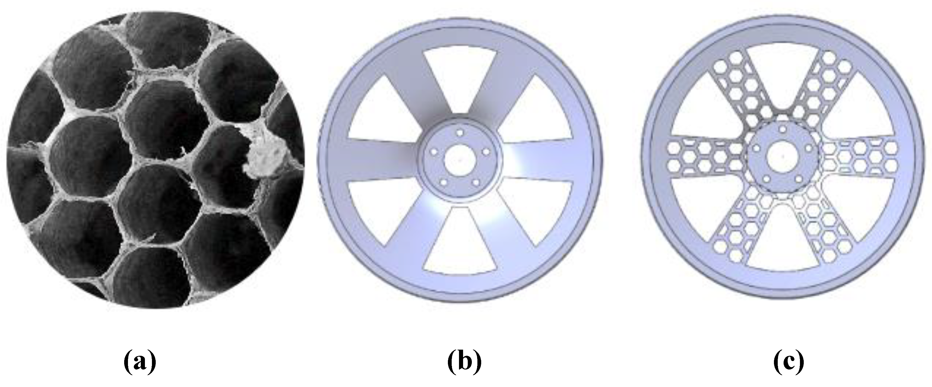
Figure 5.
Bionic wheel hub with optimized honeycomb structure.
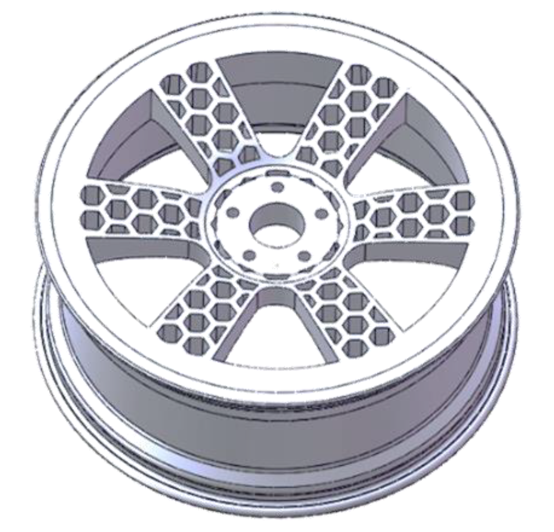
Figure 6.
Distribution of parameter structure corresponding to target optimization.
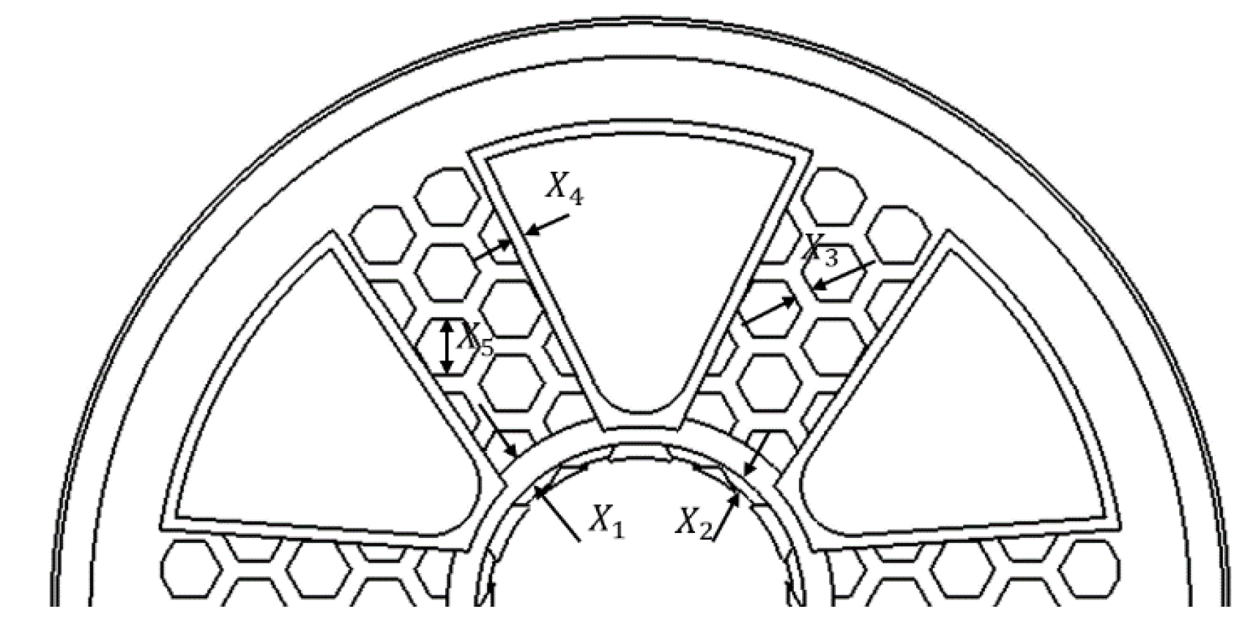
Figure 7.
(a) Gray correlation degree between target parameters and stress.
Figure 8. (b) Gray correlation degree between target parameters and quality.
Figure 7.
(a) Gray correlation degree between target parameters and stress.
Figure 8. (b) Gray correlation degree between target parameters and quality.
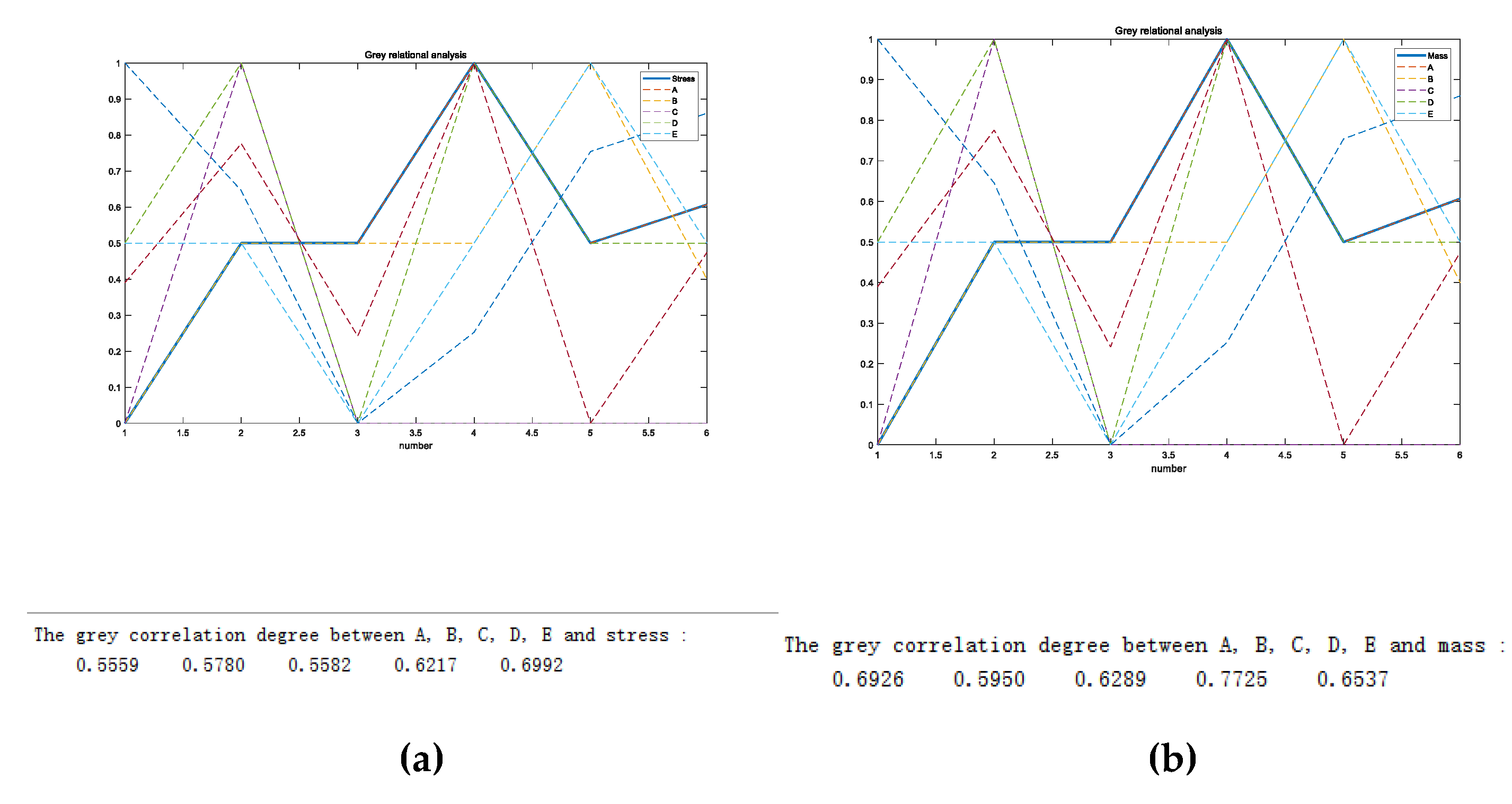
Figure 9.
Fitting diagram of simulation results of predicted value and actual value.
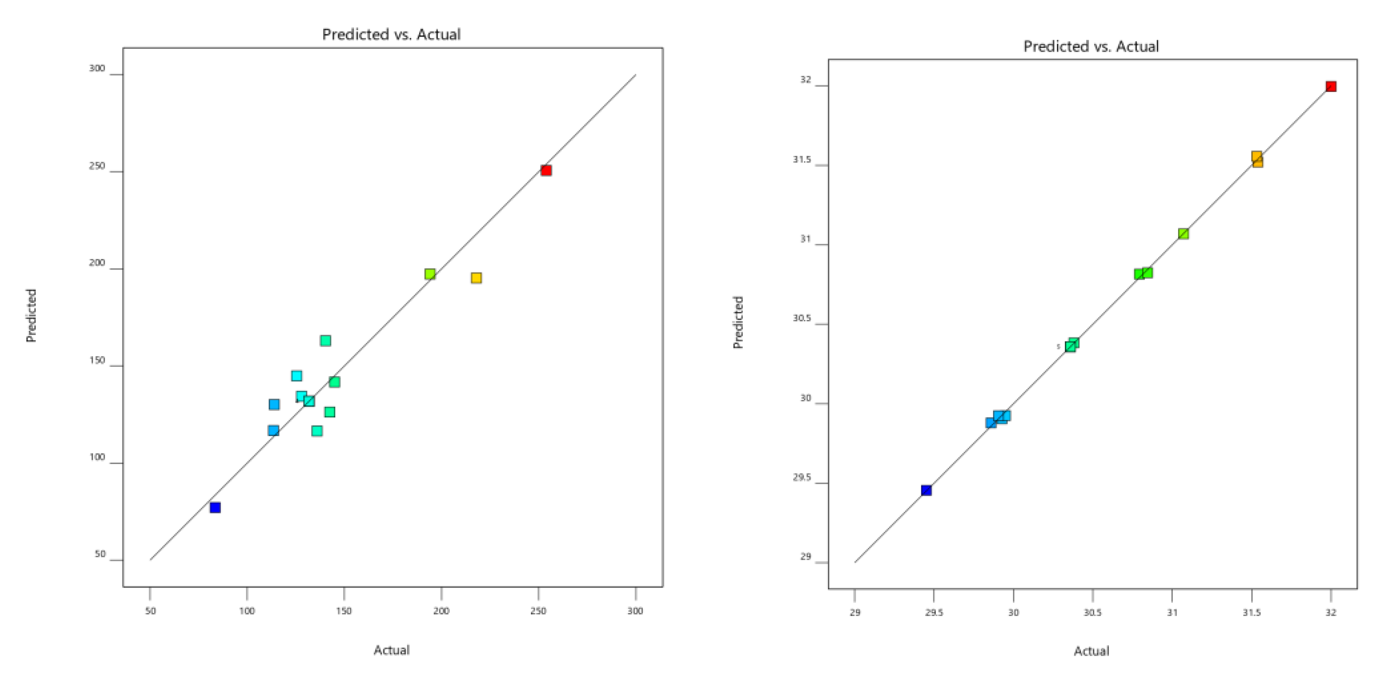
Figure 10.
(a)Interactive effects of parameters X2 and X4 on stress values; (b)Interactive effects of parameters X5 and X2 on stress values; (c)Interaction of parameters X5 and X4 on stress values.
Figure 10.
(a)Interactive effects of parameters X2 and X4 on stress values; (b)Interactive effects of parameters X5 and X2 on stress values; (c)Interaction of parameters X5 and X4 on stress values.
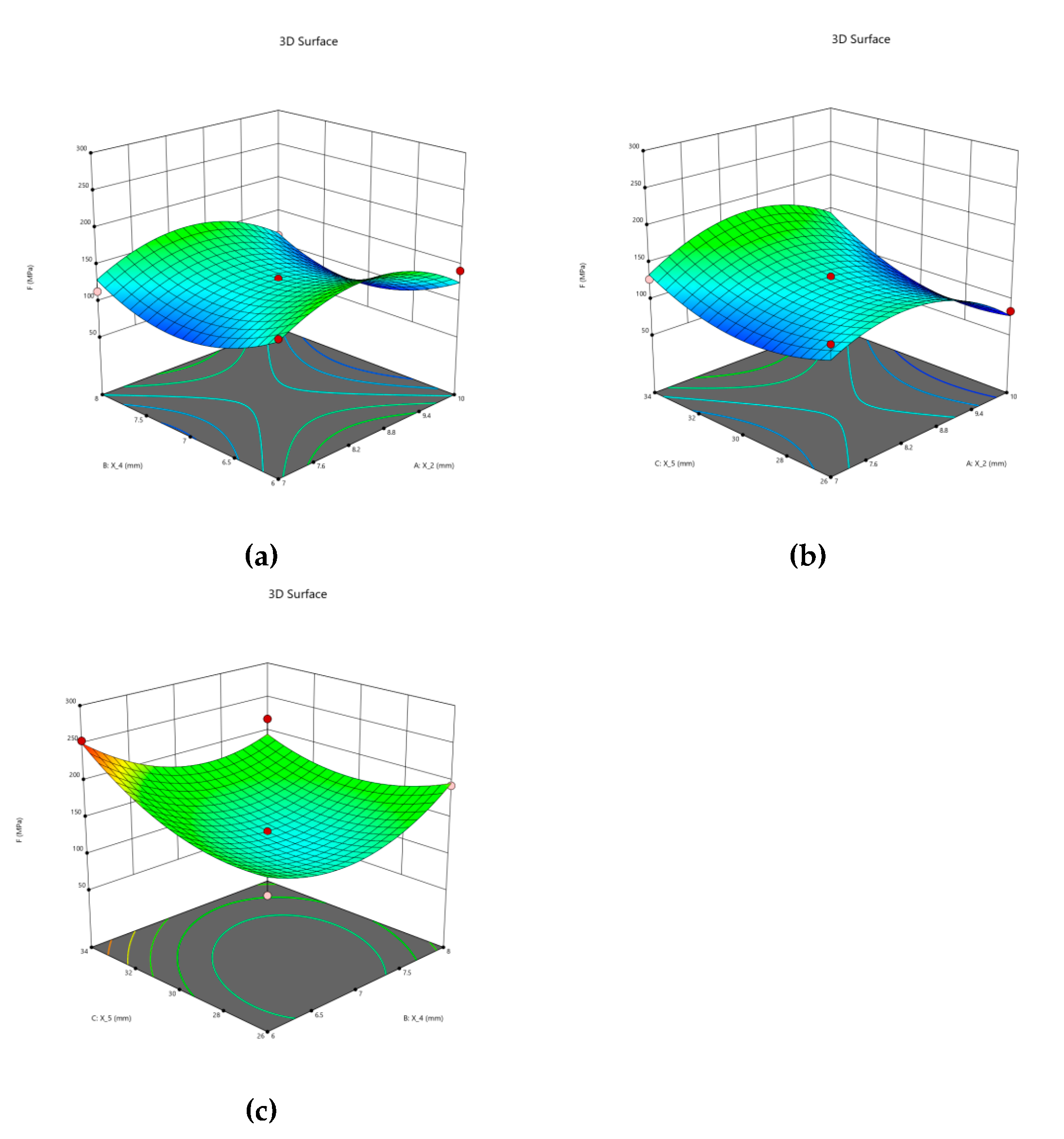
Figure 11.1.
stress nephogram and displacement of the bionic wheel of the honeycomb structure after optimization under working conditions.
Figure 11.1.
stress nephogram and displacement of the bionic wheel of the honeycomb structure after optimization under working conditions.
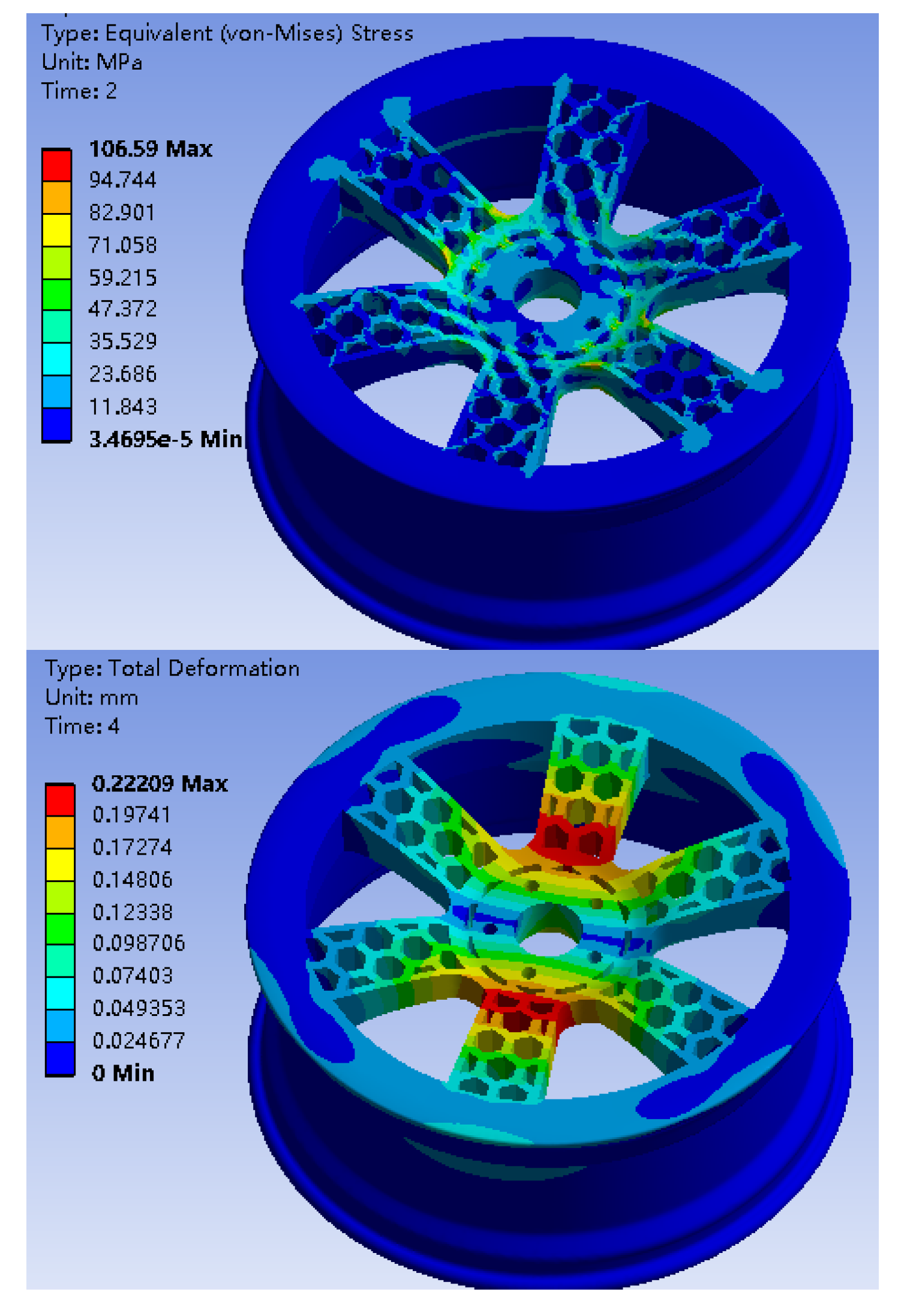
Figure 11.2.
stress nephogram and displacement of the bionic wheel of the optimized honeycomb structure under working condition 2.
Figure 11.2.
stress nephogram and displacement of the bionic wheel of the optimized honeycomb structure under working condition 2.
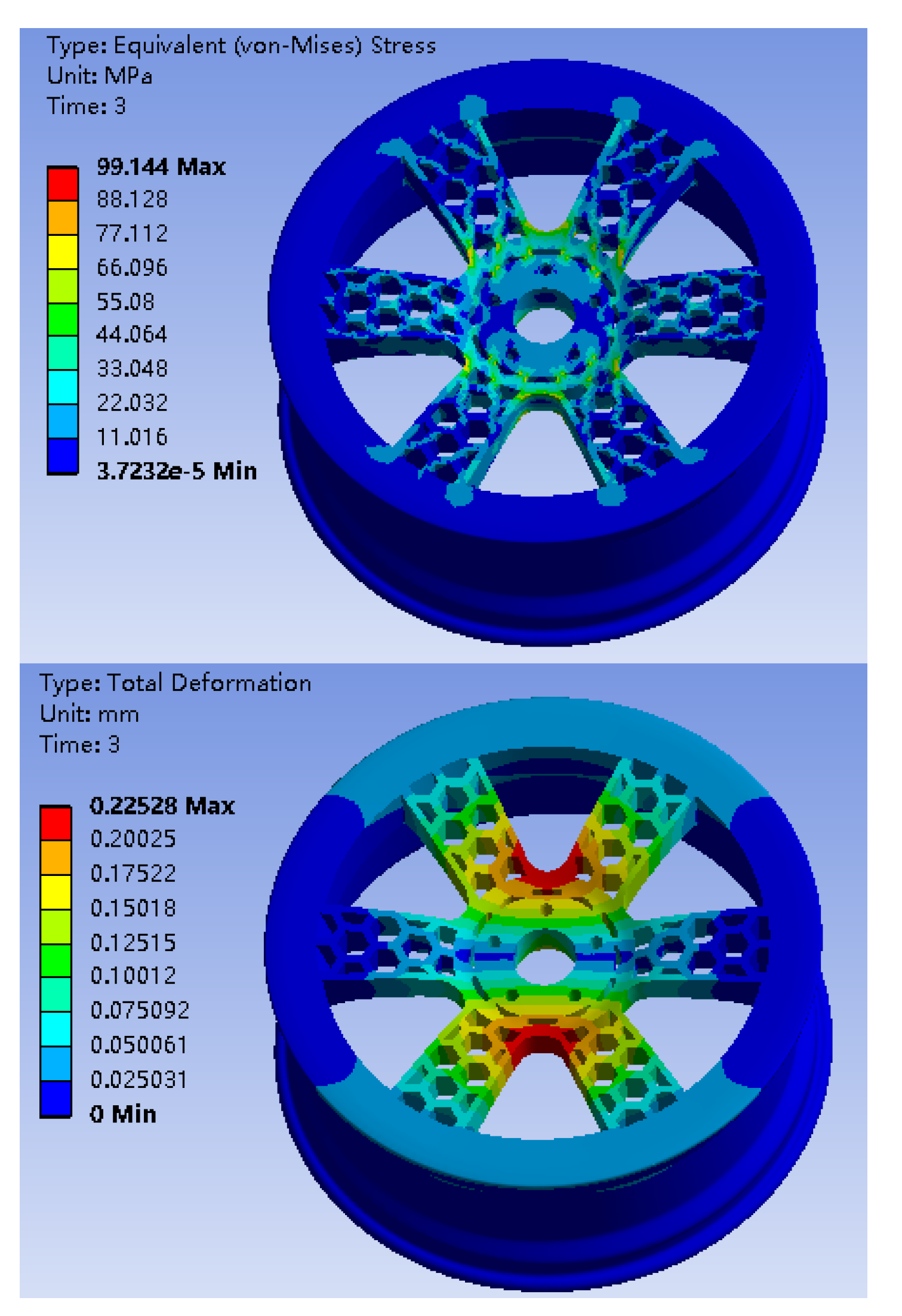
Figure 12.
Fatigue life analysis results of bionic wheel with optimized honeycomb structure.
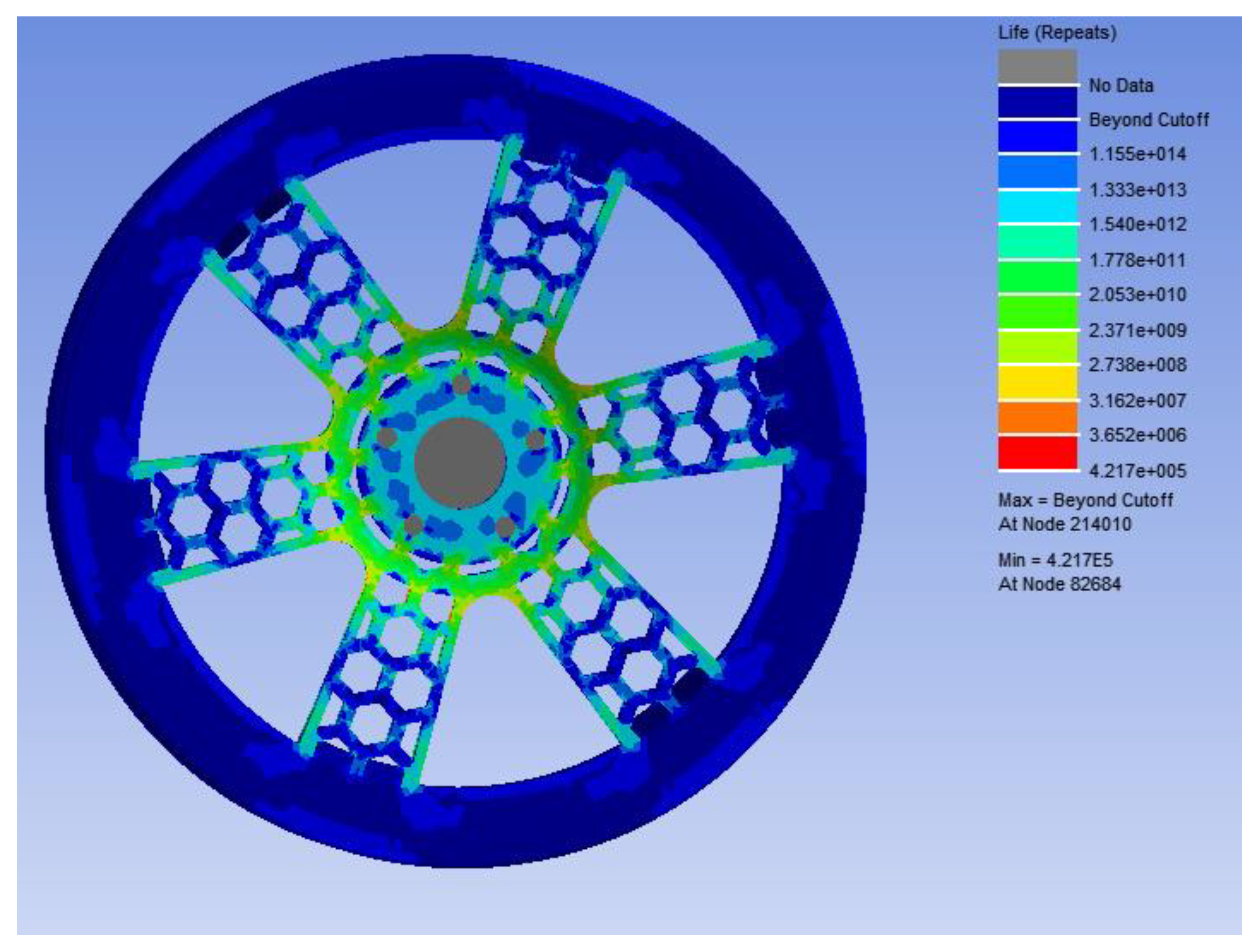
Table 1.
Properties of A356 aluminum alloy.
| Materials | Density (Kg/m3) | Young's modulus(Pa) | Poisson's ratio(MPa) | Strength limit |
|---|---|---|---|---|
| A356 Aluminium alloy | 2690 | 6.9E+10 | 0.33 | 290 |
Table 2.
GB/T 5334-2021 "Passenger Car Wheel Performance requirements and test methods" bending fatigue test cycle requirements.
Table 2.
GB/T 5334-2021 "Passenger Car Wheel Performance requirements and test methods" bending fatigue test cycle requirements.
| Materials | strengthen factor | Minimum cycle number | friction coefficient |
|---|---|---|---|
| lightweight aluminum alloy | 1.60(Optimization coefficient) | 100 000 | 0.7 |
Table 3.
Maximum stress and displacement values of ordinary wheel hub and honeycomb structure wheel hub under two working conditions.
Table 3.
Maximum stress and displacement values of ordinary wheel hub and honeycomb structure wheel hub under two working conditions.
| working conditions | Mass(Kg) | Maximum stress(MPa) | displacement(mm) |
|---|---|---|---|
| ordinary wheel hub 1 | 34.02 | 119.36 | 0.16 |
| honeycomb structure wheel hub 1 | 29.73 | 206.09 | 0.29 |
| ordinary wheel hub 2 | 34.02 | 119.77 | 0.15 |
| honeycomb structure wheel hub 2 | 29.73 | 174.94 | 0.27 |
Table 4.
Variation range of target parameters.
| Target parameter | Variation range (mm) |
|---|---|
| 14-17 | |
| 7-10 | |
| 8-12 | |
| 6-8 | |
| 26-34 |
Disclaimer/Publisher’s Note: The statements, opinions and data contained in all publications are solely those of the individual author(s) and contributor(s) and not of MDPI and/or the editor(s). MDPI and/or the editor(s) disclaim responsibility for any injury to people or property resulting from any ideas, methods, instructions or products referred to in the content. |
© 2024 by the authors. Licensee MDPI, Basel, Switzerland. This article is an open access article distributed under the terms and conditions of the Creative Commons Attribution (CC BY) license (http://creativecommons.org/licenses/by/4.0/).
Copyright: This open access article is published under a Creative Commons CC BY 4.0 license, which permit the free download, distribution, and reuse, provided that the author and preprint are cited in any reuse.


