Submitted:
08 March 2025
Posted:
10 March 2025
You are already at the latest version
Abstract
A novel expandable wheel body assembly is designed in this paper. The wheel body assembly utilizes the elastic deformation of the hub clamp the bearing assembly. The gaps between them are effectively eliminated by this structure, improving the rotational precision and operational stability of the momentum wheel. A finite element model of the momentum wheel was established, and stress analysis was conducted under constant acceleration using finite element analysis software ANSYS. The results demonstrate that the designed momentum wheel meets the required strength specifications. Additionally, the random vibration characteristics of the momentum wheel in space environments were analyzed, and a random vibration test study was conducted. The results indicate that this new type of momentum wheel can work reliably in aerospace conditions.
Keywords:
Wheel Assembly
; Bearing Assembly
; Momentum Wheel
; Finite Element Analysis
1. Introduction
The momentum wheel (MW), also known as a biased flywheel, is a crucial actuator in the attitude control system of spacecraft. By utilizing the torque generated by the high-speed rotation of the momentum wheel, satellite attitude control can be achieved. When external disturbances cause changes in satellite attitude, the momentum wheel can adjust the spacecraft’s spatial orientation by outputting control torque through high-speed rotation. Due to issues in design, manufacturing, and assembly, the momentum wheel often experiences high-frequency jitter caused by imbalance during high-speed operation, leading to output vibration force and vibration torque, a phenomenon referred to as micro-vibration. Micro-vibration of momentum wheels has become one of the primary vibration sources in high-resolution satellites, significantly affecting the pointing accuracy and stability of the satellite attitude control system, while also greatly reducing the satellite’s resolution.
To improve the quality of momentum wheels, numerous researchers have developed various wheel body and bearing assembly structures, achieving significant vibration reduction effects[1]. NASA has developed high-performance composite materials and high-precision magnetically suspended bearings[2]. The momentum wheel developed by Beacon Power Corporation in the UK utilizes a brushless motor and magnetic suspension bearings, achieving a maximum rotational speed of 30,000 rpm[3]. The University of Maryland has designed a momentum wheel with a novel composite material, control system, and magnetic bearing driver, reaching a maximum rotational speed of 20,000 rpm and an energy storage capacity of 300 Wh[4]. Bichler U et al. developed a novel momentum wheel for three-axis attitude control systems, effectively eliminating gyroscopic effects during rotation and significantly enhancing rotational accuracy[5].
A momentum wheel primarily consists of a shell assembly, wheel body assembly, bearing assembly, motor, and commutation circuitry. Among these, the wheel body assembly and bearing assembly are the key components responsible for providing control torque. Currently, most momentum wheels adopt an assembled wheel body structure, where the spokes, rim, and hub of the wheel body are joined through welding and screw connections. However, when operating in harsh space environments over extended periods, this structure suffers from insufficient connection stiffness and poor stability. Additionally, it fails to eliminate the contact gap between the hub and bearing sleeve, leading to axial and radial vibrations during operation. These vibrations contribute to micro-vibration in the momentum wheel, severely impacting the pointing accuracy and stability of the satellite attitude control system.
To meet the high stability requirements of satellite attitude control systems and address the shortcomings of traditional momentum wheel structures, it is necessary to optimize the structural design of momentum wheels. A novel expandable momentum wheel body is proposed, featuring an integrated structure that effectively mitigates deformation caused by welding and threaded connections in traditional assembled momentum wheels. Furthermore, by utilizing slight deformations of the hub, high-precision clamping of the bearing assembly can be achieved, eliminating the fit clearance between the wheel body and bearing assembly. This design enhances rotational accuracy, dynamic balance, and resistance to impact and vibration, thereby extending the lifespan of the momentum wheel while improving the pointing accuracy, stability, and reliability of the satellite attitude control system.
2. Desinge of Wheel Assembly
There are two common structural types of wheel assemblies: assembled and integral. In an assembled wheel, the rim, spokes, and hub are made from different materials and assembled using welding, screws, or other connection methods. In contrast, an integral wheel is machined from a single piece of material, with the hub, spokes, and rim forming a unified structure. Compared to assembled wheels, integral wheels can effectively reduce deformation caused by welding and threaded connections in traditional assembled momentum wheels, improve dynamic balance accuracy, and are more suitable for single-piece production with enhanced resistance to impact and vibration.
This paper breaks through the limitations of traditional thinking and improves the structure of the momentum wheel assembly. An expandable wheel assembly has been designed, which enables high-precision clamping of the bearing assembly. This structure eliminates the clearance between the hub and the shaft sleeve, improving the rotational accuracy of the momentum wheel. At the same time, it offers the advantages of easy assembly and disassembly, as well as high reliability. The expandable wheel assembly is shown in the Figure 1.
The expandable wheel assembly primarily consists of seven components: the rim, spokes, hub outer ring, hub inner ring, elastomer, push rods, and preload screws. The rim, spokes, and hub outer ring, collectively referred to as the wheel body, are forged from 40CrNiMo quenched and tempered stainless steel blanks. After heat treatment, they are shaped through overall milling, during which the fan-shaped structure between the five spokes is removed. The hub inner ring is designed with seven through holes, five of which are used to connect with the bearing assembly, and the other two are for positioning. The end faces of the hub inner ring and the wheel body are welded together to prevent the elastomer from leaking. The spoke-type wheel body has five spokes, each inclined at an angle of 9°. To facilitate processing, the cross-section of each spoke is designed with an outer square and inner circular hollow structure. Each spoke sequentially installs an elastomer, push rod, and preload screw. When the set screw is tightened, it pushes the push rod to move radially within the spoke cavity, causing the elastomer to flow. The thin-walled structure of the hub inner ring deforms elastically under pressure, achieving high-precision clamping of the bearing assembly.
3. Design of Bearing Assembly
Momentum wheels mostly use high-precision angular contact ball bearings for support. The bearing assembly consists of two angular contact ball bearings installed back-to-back. It is essential for the bearing assembly to have good lubrication performance to reduce friction and wear, ensuring the long lifespan and high stability of the momentum wheel. The structure of the bearing assembly is shown in Figure 2.
4. Overall Design of Momentum Wheel
The motor and shell assembly are also essential components of the momentum wheel. Most existing momentum wheels utilize brushless DC motors, which feature a coreless stator design. These motors offer advantages such as long lifespan, high reliability, and low power consumption, fully meeting the technical requirements of satellite attitude control systems. The shell assembly is made of titanium alloy, which enhances the internal vacuum level of the momentum wheel while also satisfying the weight reduction requirements in aerospace applications.
By assembling the expandable wheel body, bearing assembly, motor, and shell, the expandable momentum wheel designed in this study is formed, with its overall model illustrated in Figure 3.
Figure 3 shows the main components of the expandable momentum wheel, including the expandable wheel body, bearing assembly, motor, and shell. During installation, the bearing assembly and motor rotor are first mounted onto the lower shell. The wheel body assembly is then installed onto the bearing sleeve, with the wheel hub secured using five screws. Subsequently, the radial positions of the five screws in the spokes are adjusted, applying pressure to the elastic bodies within the spokes. This pressure induces a slight elastic deformation in the inner hub ring, achieving high-precision clamping with the bearing assembly.
Additionally, the momentum wheel adopts an integral wheel body structure, significantly enhancing the strength of the wheel body and improving its resistance to impact and vibration in the complex space dynamics environment. This design extends the operational lifespan of the momentum wheel and improves its overall performance in satellite attitude control applications.
5. Finite Element Analysis Under Constant Acceleration Environment
During spacecraft launch, the momentum wheel undergoes sustained acceleration, leading to mechanical stress and dynamic loads. To ensure its structural integrity and reliable operation, a strength analysis is necessary to assess potential deformations, material fatigue, and stress concentrations.
5.1. Simplification of the Finite Element Model of Angular Contact Ball Bearings
The wheel body assembly uses a set of back-to-back angular contact ball bearings (B7004) for support, which needs to be simplified. The dimensional parameters of the angular contact bearings are provided in Table 1, with radial stiffness and axial stiffness . In ANSYS, two radial and one inclined spring-damping unit (COMBIN14) are used to replace each bearing ball, with a total of 8 sets. The tilt angle represents the bearing contact angle. The inner and outer rings of the bearing are retained. The simplified bearing model is shown in Figure 4.
The following section calculates the stiffness of the radial and inclined COMBIN14 spring-damping units based on the radial and axial stiffness of the bearing. According to the stiffness equivalence principle and the bearing simplification schematic, we have:
The solution yields .
5.2. Establishment of the Finite Element Model of the Momentum Wheel
In this study, ANSYS is used to conduct the mechanical analysis of the momentum wheel under a constant acceleration environment. The momentum wheel consists of the wheel body assembly, bearing assembly, motor, and shell assembly. If a finite element model is established based on the actual structure of the momentum wheel, computational efficiency would be significantly reduced. In practice, small features such as screw holes, chamfers, and fillets have minimal impact on the overall finite element analysis results of the momentum wheel. Therefore, details on the wheel body, bearing assembly, motor, and shell have been simplified. SOLID186 is a higher-order solid element suitable for meshing curved surfaces, making it the chosen element type for this study. The momentum wheel is meshed using tetrahedral elements. The material properties of each component of the momentum wheel are listed in Table 2.
During the launch process of the spacecraft, the momentum wheel is subjected to acceleration environments in all directions. In the simulation, inertial accelerations of 10g are applied separately in the x, y, and z directions. When applying inertial acceleration in one direction, the degrees of freedom in the other two directions must be constrained. The finite element model of the expandable momentum wheel is shown in Figure 5.
5.3. Analysis of Finite Element Simulation Results
The radial acceleration of the spindle is set to 10g. The simulation results for the von Mises stress distribution are shown in Figure 6. From Figure 6 the maximum overall stress of 17.2 MPa occurs at the connection between the bearing inner and outer races and the COMBIN14 units. From Figure 6, the maximum stress of 0.92 MPa in the wheel body assembly occurs at the connection between the spokes and the rim. The axial acceleration of the spindle is set to 10g. The simulation results are shown in Figure 7. From Figure 7, the maximum overall stress of 18.7 MPa occurs at the connection between the bearing inner and outer races and the COMBIN14 units. From Figure 7, the maximum stress of 1.19 MPa in the wheel body assembly occurs at the connection between the spokes and the outer hub ring. Thus, the momentum wheel can operate safely and reliably in a constant acceleration environment.
6. Random Vibration Response Analysis of the Momentum Wheel
Random vibration is a type of dynamic environment vibration, primarily originating from launch exhaust noise and aerodynamic noise during flight, with a frequency range of approximately 20-2000 Hz. This vibration environment can dynamically propagate to the structural or instrumental levels of spacecraft, including system-level, subsystem-level, or component-level structures. It may cause structural damage, leading to performance degradation or even failure of instruments and equipment, posing significant threats to the safe operation of spacecraft.
Therefore, this section conducts a random vibration test on the momentum wheel to verify its reliability under a random vibration environment.
6.1. Frequency Characteristics Analysis of Random Vibration
Let be the random vibration excitation applied to the system in the time domain. According to Parseval’s theorem, it can be transformed into the frequency domain as:
where is the random vibration excitation in the frequency domain.
By applying the Fourier transform to the autocorrelation function , we obtain:
where is the power spectral density function of the random vibration.
The inverse transform of this equation is:
For equation (4), if we set , then:
It is known that the autocorrelation function satisfies:
where is the mean square value of the random vibration, which represents the total energy of the random vibration.
From the above equations, the power spectral density function represents the distribution of the mean square value of the random vibration in the frequency domain. In other words, the power spectral density function indicates the energy distribution across frequencies.
6.2. Statistical Characteristics of Random Vibration Response
The response of a linear system under any excitation can be obtained using the convolution integral:
Extending the integration limits of equation (8) to and does not affect the result, yielding:
Let be the random vibration excitation applied to the system, and let be its response.
The autocorrelation function of the random vibration response is given by:
After calculation, the power spectral density of the random vibration response is:
where is the power spectral density of the random vibration excitation, and is the system’s frequency response function.
The mean square value of the response is:
From equation (12), it is evident that given the power spectral density of the random vibration excitation and the system’s frequency response function, the random vibration response of the system can be determined.
When the system is subjected to multiple independent and uncorrelated random vibration excitations, the total response power spectral density is the sum of the power spectral densities of each excitation response:
Equation (13) indicates that the system’s random vibration response depends not only on external excitations but also on the system’s inherent characteristics. In random vibration response analysis, studying the relationship between applied random vibration excitation and the system’s response can reveal structural characteristics and assess the reliability of the structure.
6.3. Random Vibration Experiment
To verify the reliability of the expandable momentum wheel and assess its ability to withstand vibration environments, a random vibration test was conducted using specialized equipment to simulate the space vibration environment. Prior to the experiment, a dynamic balancing test was performed on the momentum wheel, achieving a static imbalance of 122 mg·cm and a dynamic imbalance of 693 mg·cm². The wheel was then sealed and subjected to a vacuum treatment.
The momentum wheel was mounted onto the vibration table using bolts. Measurement point A1 was placed at the crown top of the sheel, while measurement point A2 was located on the welded band of the shell side to measure the corresponding acceleration at these positions. Additionally, a control point was set on the base of the momentum wheel to provide feedback on the vibration conditions applied by the vibration table. A schematic diagram is shown in Figure 8. According to the design requirements, the acceleration power spectral density (PSD) curves for random vibration in the x, y, and z directions are depicted in Figure 9, with a sweep duration of 1 minute.
The control spectral curves for the random vibration test are shown in Figure 10, where the AlamHigh curve represents the upper tolerance band, the AlamLow curve represents the lower tolerance band, and the Control curve is the actual control spectral curve. Since the acceleration PSD curves for the x and y directions at the control point are identical, the y-direction control spectral curve is omitted. As observed in the figure, the control spectral curves for the x and z directions fall within the tolerance band, indicating that the applied test conditions are within the allowable error range.
The response spectral curves of measurement points A1 and A2 in the x, y, and z directions are shown in Figure 11, Figure 12, Figure 13 respectively.
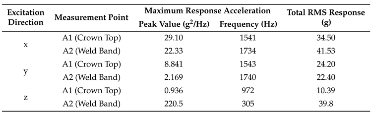
For ease of analysis, the maximum and total root mean square (RMS) acceleration responses at each measurement point were statistically evaluated, as summarized in Table 3.
From Table 3, it can be seen that under x-direction excitation, the maximum response accelerations at measurement points A1 and A2 are significantly higher than those under y- and z-direction excitation. However, under z-direction excitation at 305 Hz, the response acceleration at measurement point A2 reaches 220 g²/Hz. Furthermore, the total RMS response under x-direction excitation is also considerably higher than in the other two directions, with the highest total RMS response of approximately 41.53 g occurring at A2. According to the requirements for random vibration acceleration response in the space dynamic environment, the total RMS response required for the reliable operation of the momentum wheel is 70 g, indicating that the momentum wheel meets the response requirements for random vibration. Additionally, after completing the vibration test, the expandable momentum wheel was disassembled, and its components—including the wheel body, main shaft, bearings, and bushings—were inspected. No fractures or permanent deformations were observed, further confirming that the expandable momentum wheel meets the strength requirements.
7. Conclusion
A novel expandable momentum wheel was independently designed, utilizing the elastic deformation of the hub to achieve high-precision clamping of the bearing sleeve. This design effectively reduces the vibratory force generated during rotation, thereby enhancing the stability of the momentum wheel in the space dynamic environment while improving its impact resistance and overall reliability. Based on the stiffness equivalence principle, the finite element model of the momentum wheel was established by simplifying the finite element model of the angular contact ball bearing, and its mechanical response under constant acceleration conditions was analyzed. The results indicate that the designed momentum wheel meets the strength requirements during the launch process. Furthermore, a random vibration test was conducted by setting a reasonable acceleration power spectral density to simulate the space random vibration environment. The acceleration response spectra at two measurement points were analyzed, and the results further verified that the designed momentum wheel satisfies the strength requirements under space random vibration conditions.
References
- Narayan, S.S.; Nair, P.; Ghosal, A. Dynamic interaction of rotating momentum wheels with spacecraft elements. Journal of Sound and Vibration 2008, 315, 970–984. [Google Scholar]
- Christopher, D.A.; Beach, R. Flywheel technology development program for aerospace applications. IEEE Aerospace and Electronic Systems Magazine 1998, 13, 9–14. [Google Scholar]
- Hockney, R.; Driscoll, C. Powering of standby power supplies using flywheel energy storage. In Proceedings of the Proceedings of Power and Energy Systems in Converging Markets, 1997, pp. 105–109. [CrossRef]
- Kirk, J.A.; Walsh, G.C.; Hromada, L.P.; Zmood, R.B.; Sullivan, G.E. The open core composite flywheel. In Proceedings of the IECEC-97 Proceedings of the Thirty-Second Intersociety Energy Conversion Engineering Conference (Cat. No. 97CH6203). IEEE, 1997, Vol. 3, pp. 1748–1753.
- Bichler, U.; Eckardt, T. A 3(5) Degree of Freedom Electrodynamic-Bearing Wheel for 3-Axis Spacecraft Attitude Control Applications. In Proceedings of the Magnetic Bearings; Schweitzer, G., Ed., Berlin, Heidelberg, 1989; pp. 13–22.
Figure 1.
The structure of expandable wheel assembly. 1. Rim; 2. Spokes; 3. Hub outer ring; 4. Hub inner ring; 5. Elastomer; 6. Push rods; 7. Preload screws.
Figure 1.
The structure of expandable wheel assembly. 1. Rim; 2. Spokes; 3. Hub outer ring; 4. Hub inner ring; 5. Elastomer; 6. Push rods; 7. Preload screws.
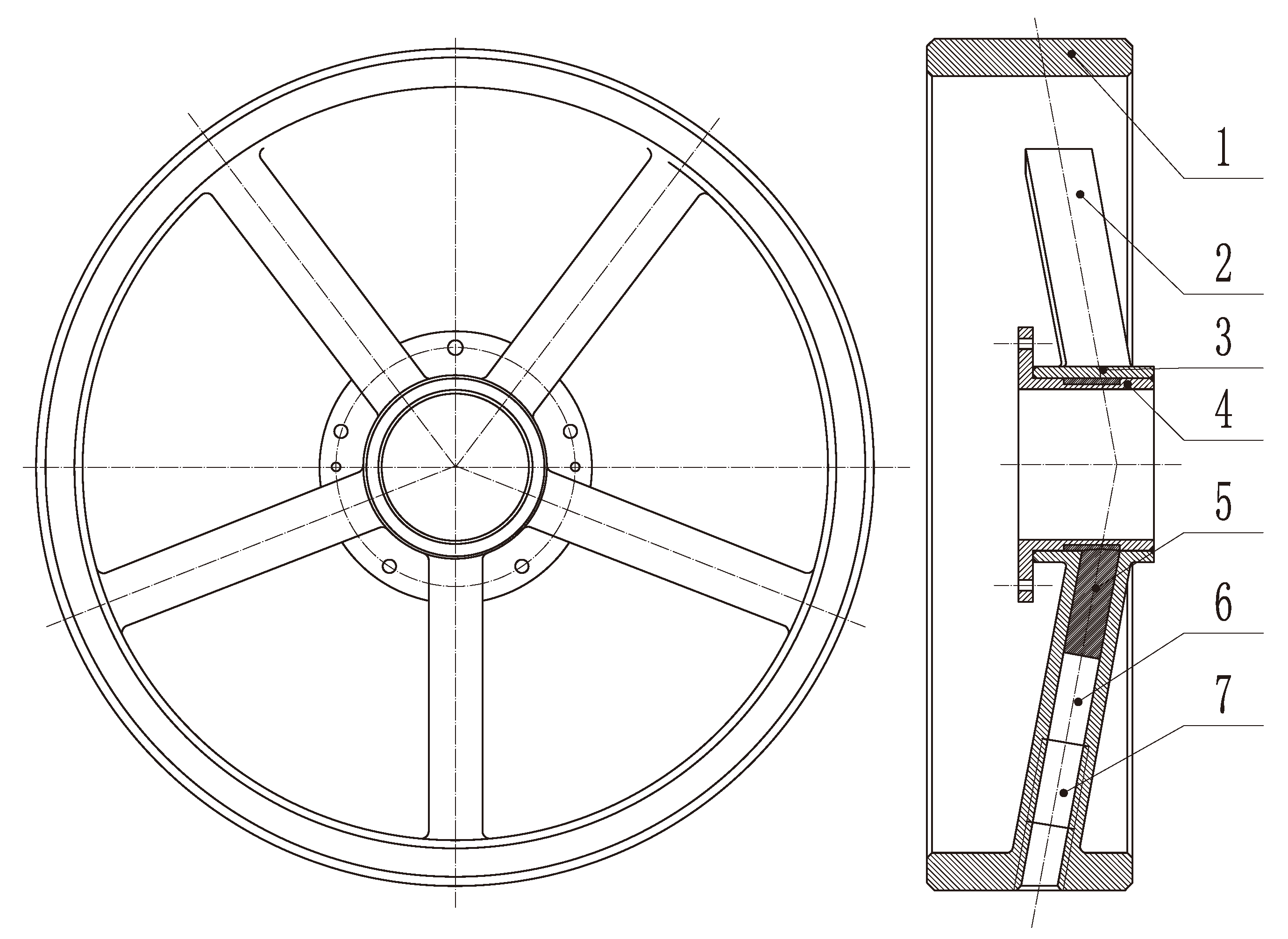
Figure 2.
The structure of the bearing assembly. 1. Spindle; 2. Shaft sleeve; 3. Inner retaining ring; 4. Outer retaining ring; 5. Inner locating sleeve; 6. Outer locating sleeve; 7. Bearing sleeve; 8. Inner sleeve; 9. Outer sleeve; 10. Bearing.
Figure 2.
The structure of the bearing assembly. 1. Spindle; 2. Shaft sleeve; 3. Inner retaining ring; 4. Outer retaining ring; 5. Inner locating sleeve; 6. Outer locating sleeve; 7. Bearing sleeve; 8. Inner sleeve; 9. Outer sleeve; 10. Bearing.
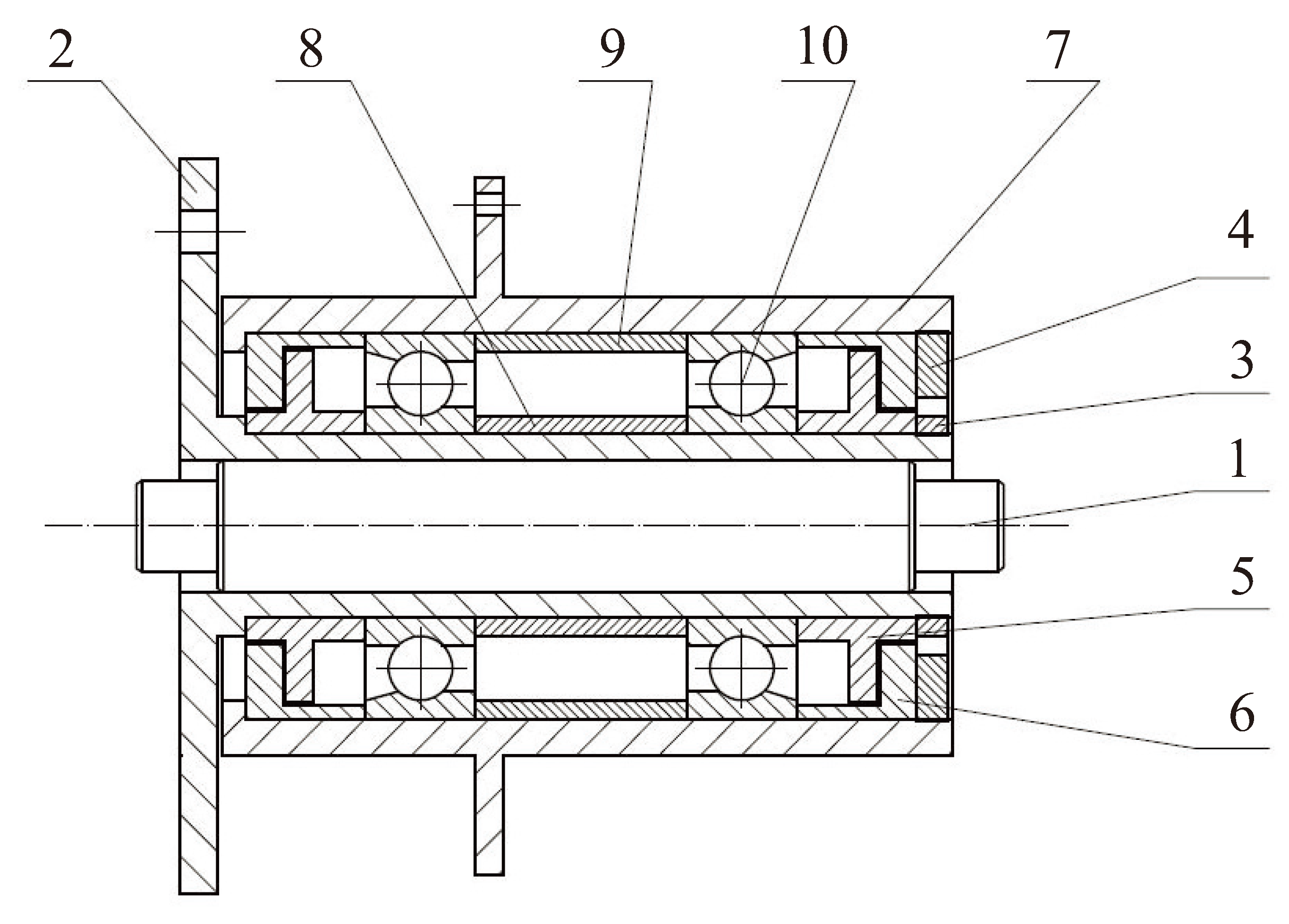
Figure 3.
Overall Model of the Momentum Wheel. 1. Wheel body assembly; 2. Bearing assembly; 3. Motor; 4. Shell assembly.
Figure 3.
Overall Model of the Momentum Wheel. 1. Wheel body assembly; 2. Bearing assembly; 3. Motor; 4. Shell assembly.
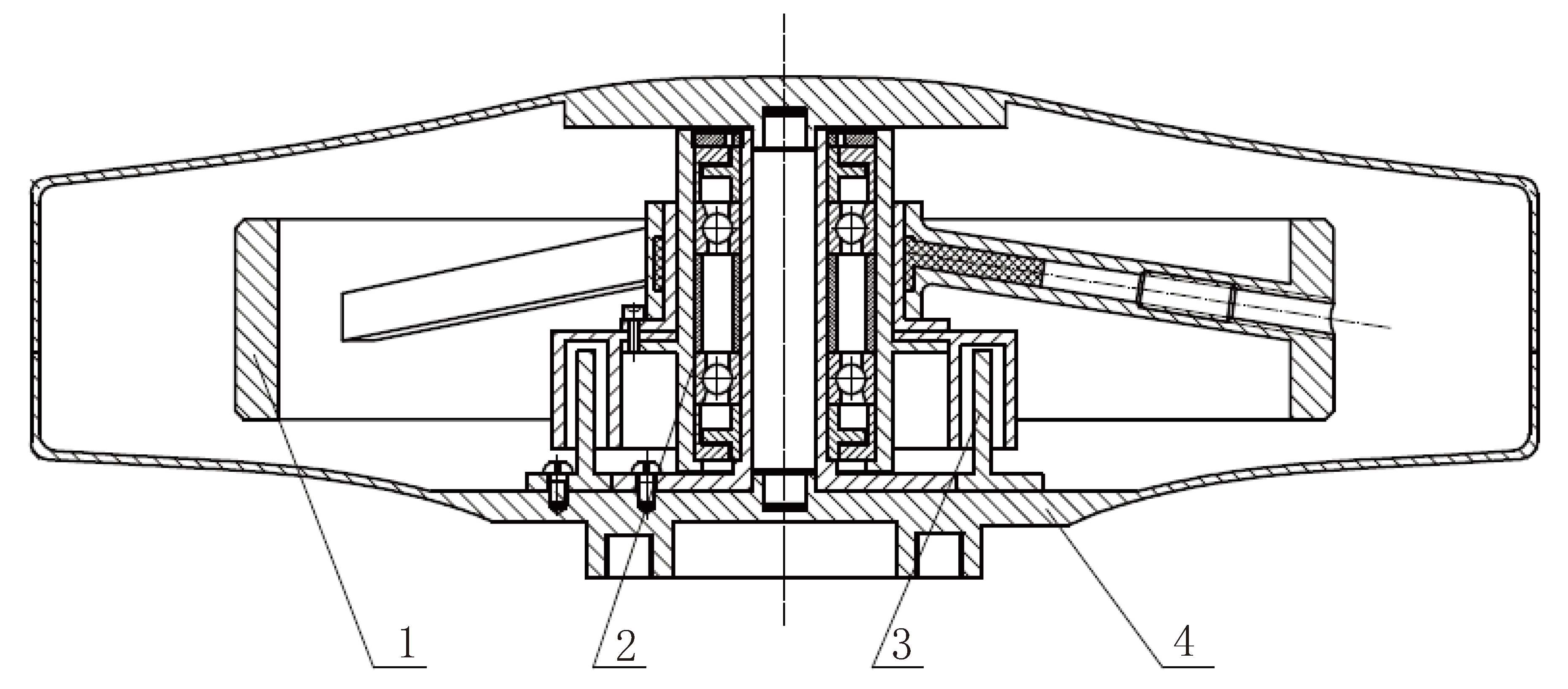
Figure 4.
The simplified bearing model.
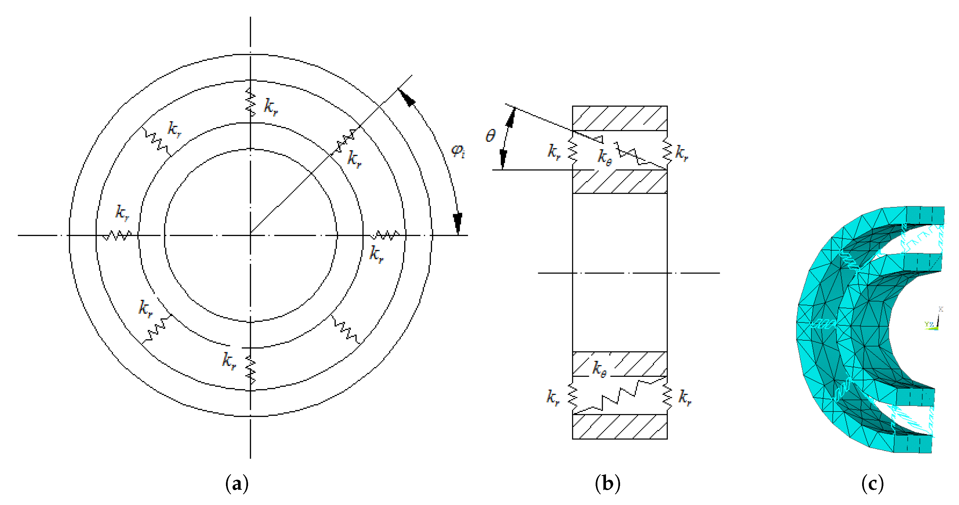
Figure 5.
FEM model of the momentum wheel
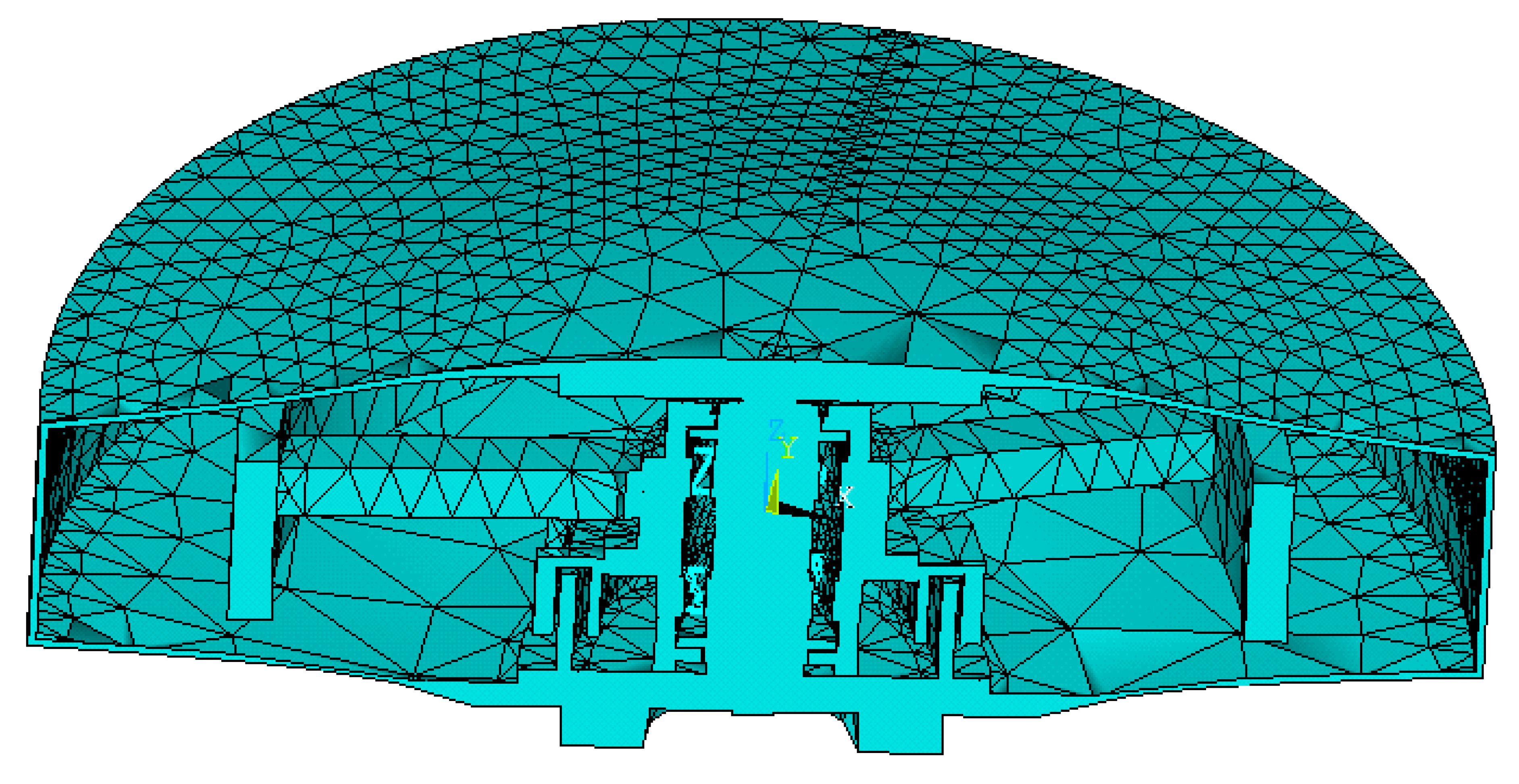
Figure 6.
Mises stress distribution under a 10g radial load
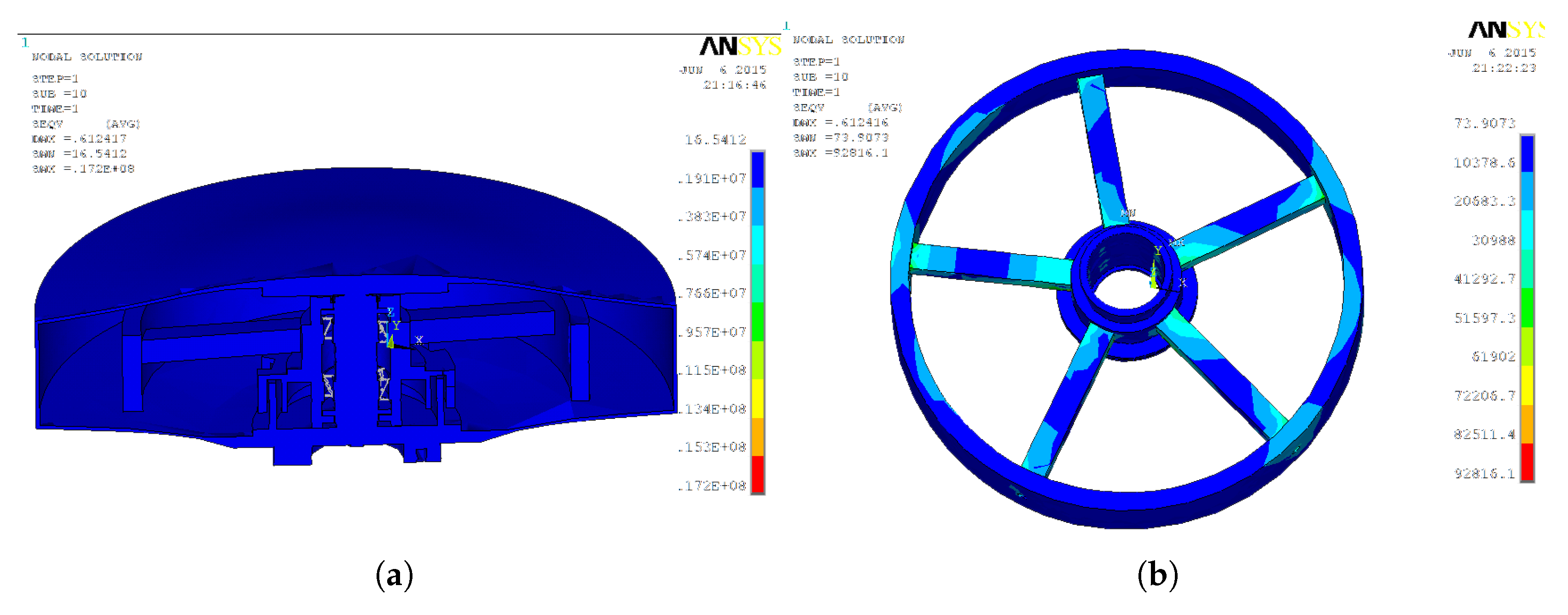
Figure 7.
Stress distribution under a 10g axial load
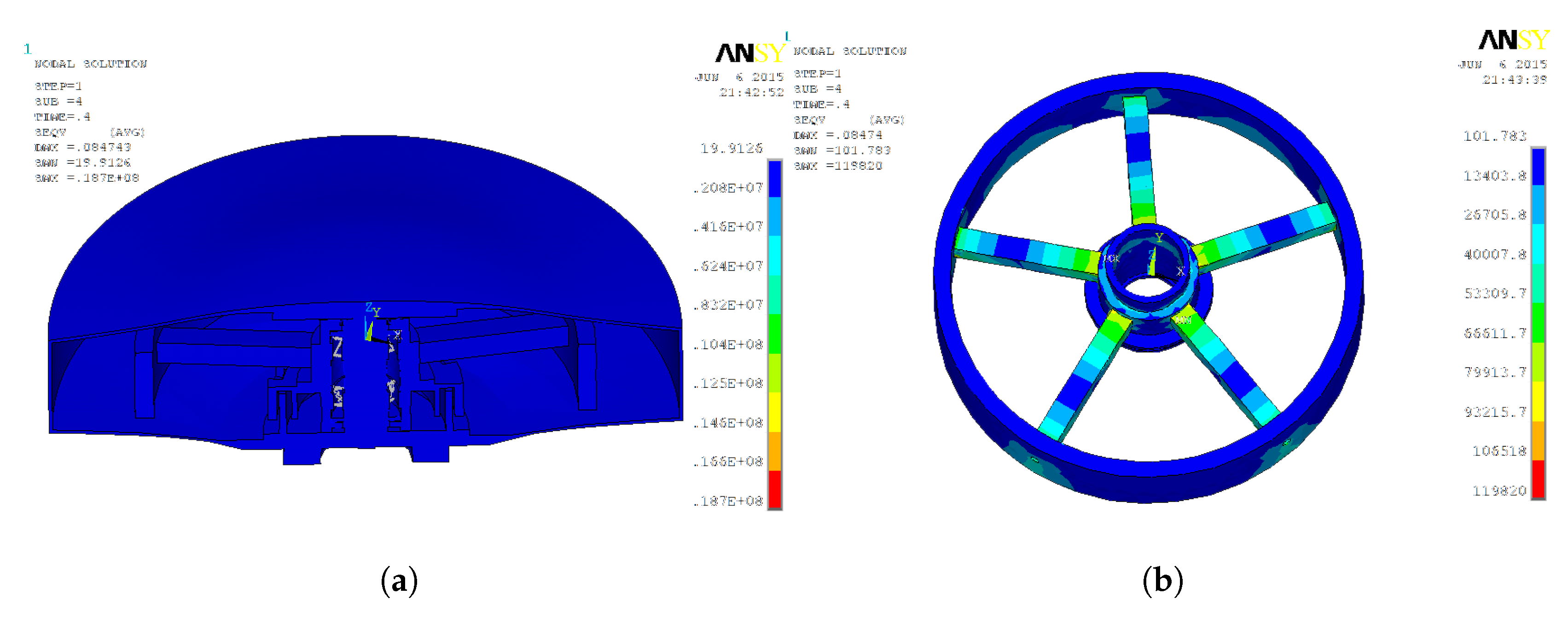
Figure 8.
Measurement points
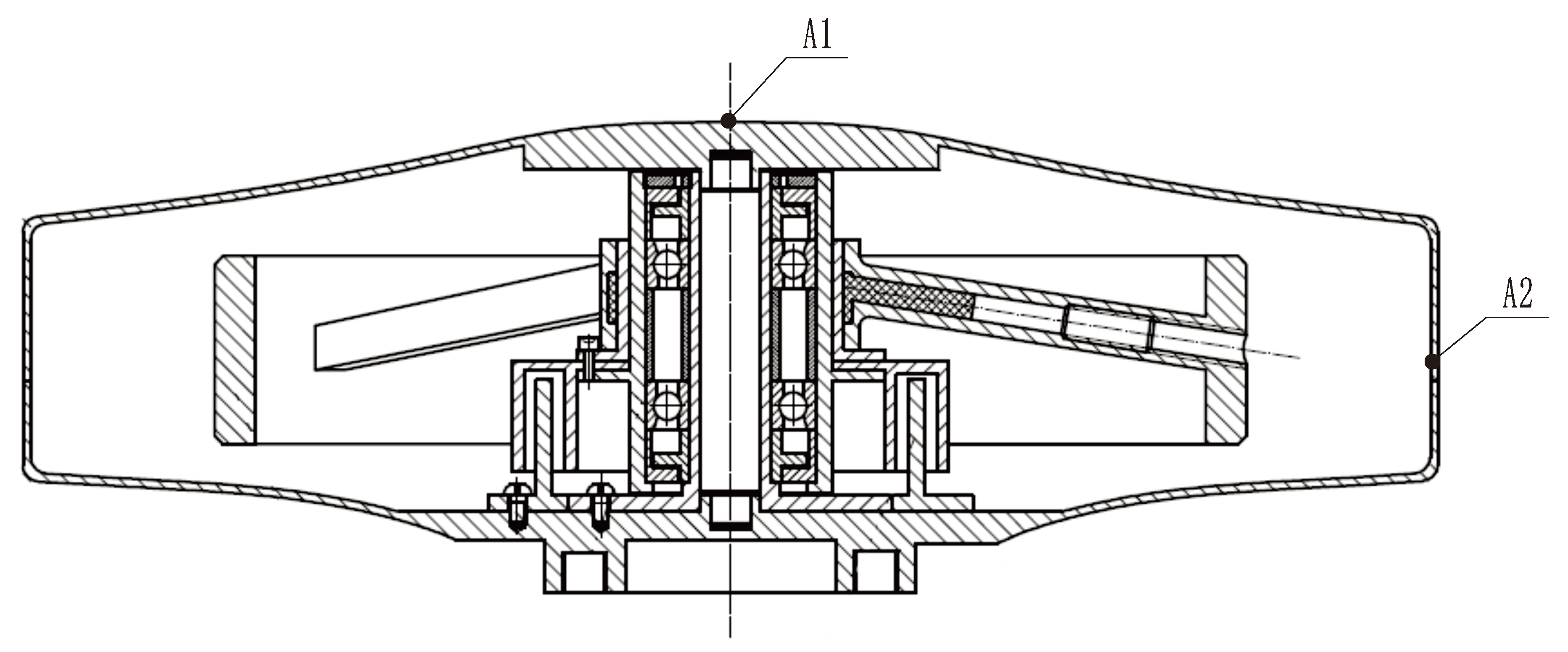
Figure 9.
Power spectral density of random vibration in different directions. (a) X/y directions. (b) Z direction. The horizontal axis represents frequency, and the vertical axis represents the acceleration power spectral density (Same for the following figure).
Figure 9.
Power spectral density of random vibration in different directions. (a) X/y directions. (b) Z direction. The horizontal axis represents frequency, and the vertical axis represents the acceleration power spectral density (Same for the following figure).
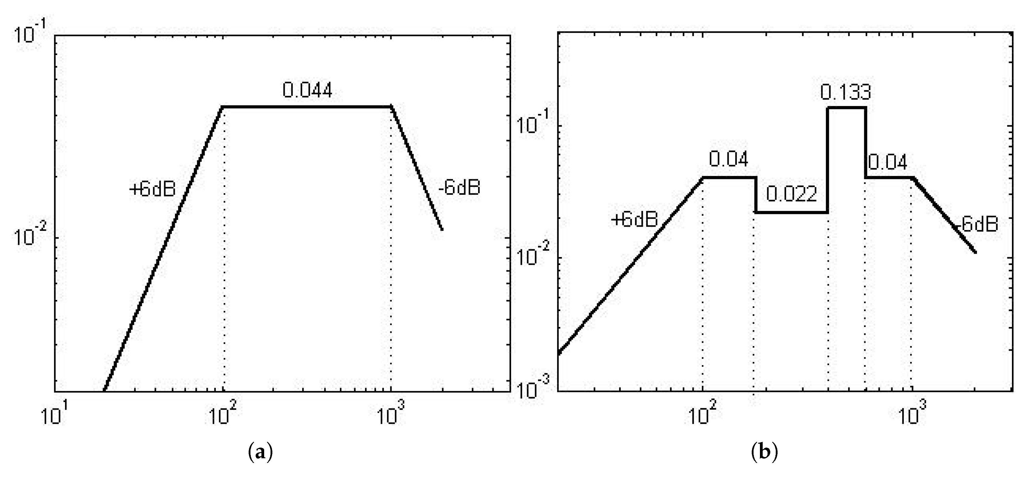
Figure 10.
Control Spectrum. (a) X direction. (b) Z direction.
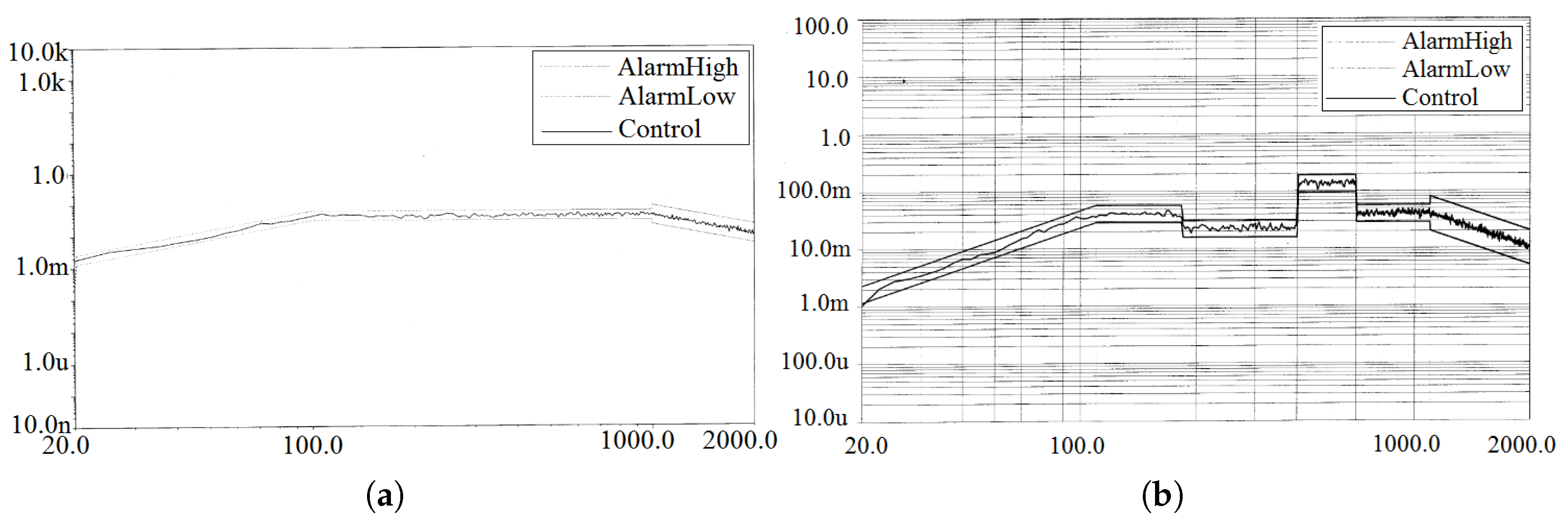
Figure 11.
X Response Spectrum. (a) Measurement point A1. (b) Measurement point A2.
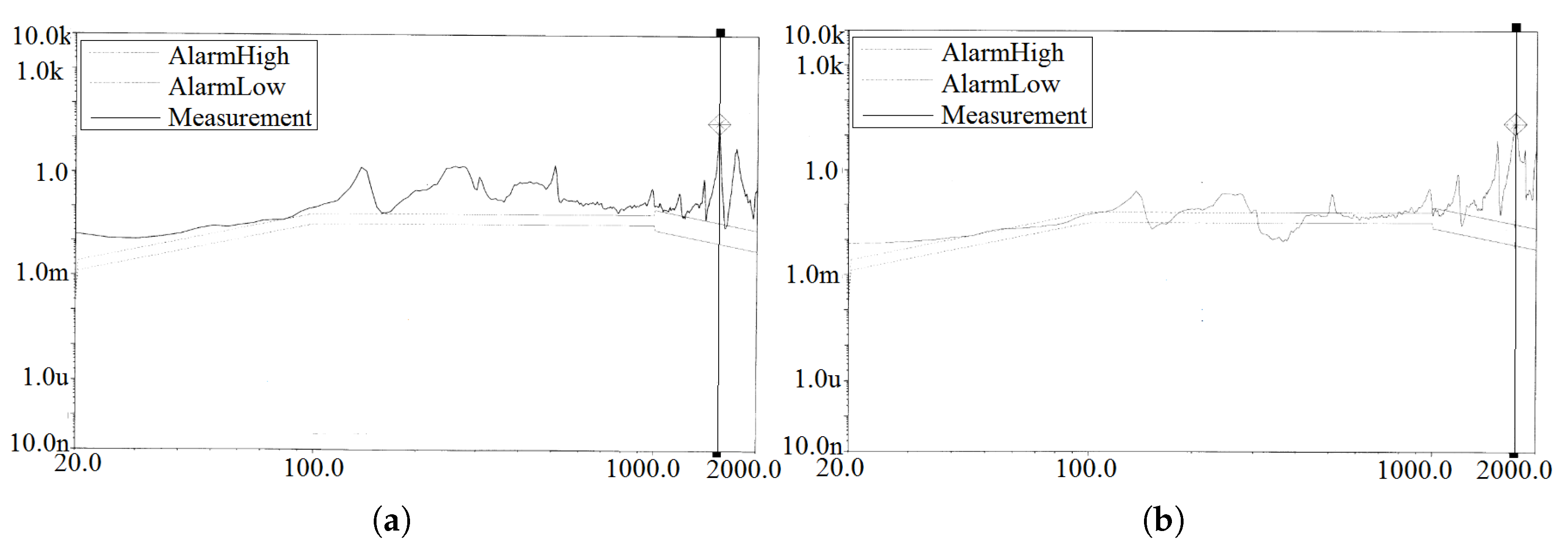
Figure 12.
Y Response Spectrum. (a) Measurement point A1. (b) Measurement point A2.
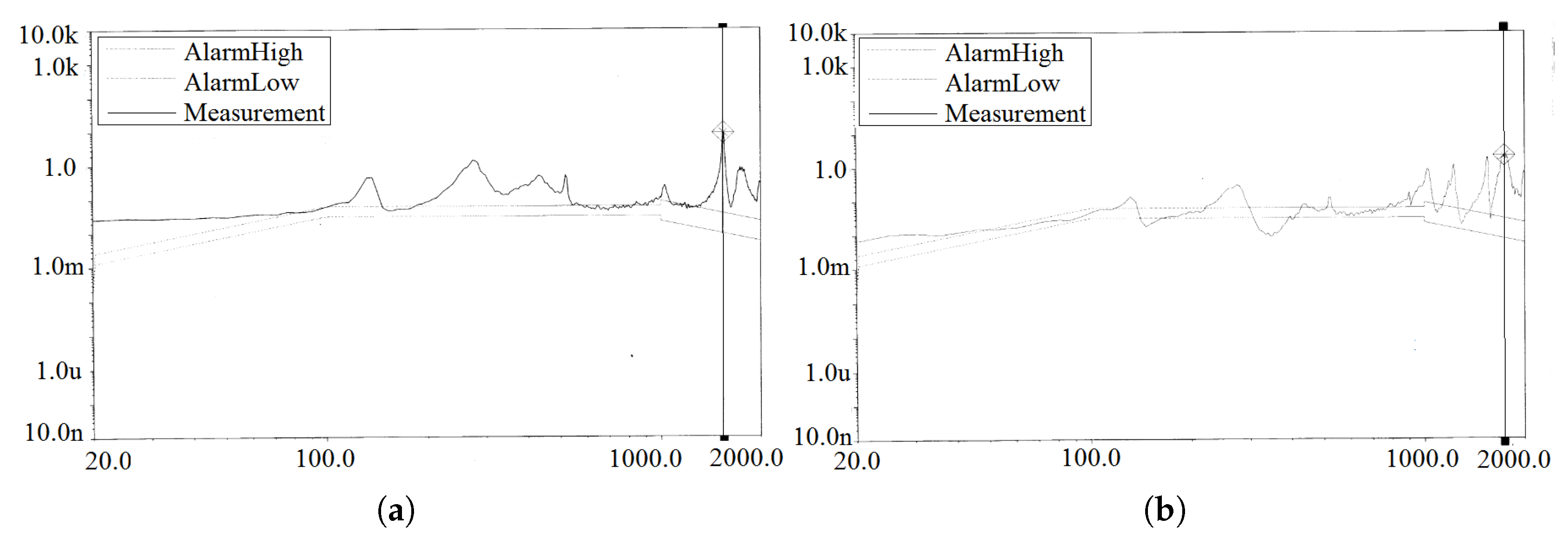
Figure 13.
Z Response Spectrum. (a) Measurement point A1. (b) Measurement point A2.
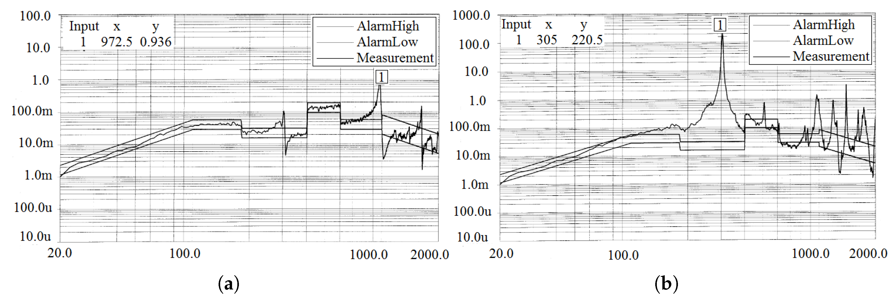

Table 1.
Dimensional parameters of angular contact ball bearings B7004
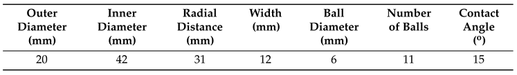 |
Table 2.
Material properties of each part of the momentum wheel
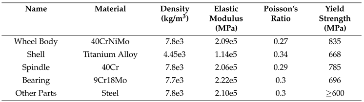 |
Table 3.
Acceleration Response Statistics Table
 |
Disclaimer/Publisher’s Note: The statements, opinions and data contained in all publications are solely those of the individual author(s) and contributor(s) and not of MDPI and/or the editor(s). MDPI and/or the editor(s) disclaim responsibility for any injury to people or property resulting from any ideas, methods, instructions or products referred to in the content. |
© 2025 by the authors. Licensee MDPI, Basel, Switzerland. This article is an open access article distributed under the terms and conditions of the Creative Commons Attribution (CC BY) license (http://creativecommons.org/licenses/by/4.0/).
Copyright: This open access article is published under a Creative Commons CC BY 4.0 license, which permit the free download, distribution, and reuse, provided that the author and preprint are cited in any reuse.


