Submitted:
11 October 2025
Posted:
13 October 2025
You are already at the latest version
Abstract
We report on the first open-source FDM 3D printer capable of fabricating its complete electromechanical ecosystem—motors, solenoids, memory systems, and control elements—representing a fundamental advance toward true mechanical self-replication. While previous self-replicating printers produced only structural components, our platform manufactures functional electronics comparable to commercial counterparts: solenoid actuators matching conventional benchmarks (108 ± 5 μJ vs. 99 ± 1.5 μJ), a three-pole brushed DC motor with performance paralleling commercial units, and dual memory architectures: functional mechanical (1639 bits/g) and developmental magnetic systems with theoretical density (5468 bits/g) encoding. The critical innovation lies not in individual components but in their integration within a single fabrication ecosystem, where printed memory directly controls printed actuators without external electronics. Using only standard FDM hardware and accessible materials, we demonstrate that low-cost printers can produce the control, storage, and motion subsystems necessary for autonomous operation. This work establishes that self-sustaining manufacturing—where machines reproduce their own functional components—is achievable with existing additive manufacturing technology, with profound implications for distributed production, space exploration, and resilient supply chains.
Keywords:
self-replicating machines
; print-in-place actuators
; magnetic memory
; self-replicating 3D printers
1. Introduction
1.1. Summary
Modern manufacturing relies heavily on centralized production for efficiency and globalization for wide-scale distribution [1]. While this model delivers substantial economic benefits under stable conditions, it is highly vulnerable to disruption. Trade disputes, geopolitical conflicts, and shifting international relations can fracture supply chains, undermining the cost-effectiveness of overseas manufacturing and destabilizing the economic assumptions behind business planning [2,3]. Likewise, disruptions at key trade choke points—whether from accidents, military operations, or natural disasters—can cause costly delays or the outright loss of critical goods [4,5]. The rigidity of global supply chains further limits their ability to adapt rapidly in times of urgent demand, as was starkly illustrated during the Covid-19 pandemic [6]. Distributed manufacturing, defined as producing equivalent products at multiple sites using localized resources, offers a promising alternative to mitigate these vulnerabilities by reducing or bypassing reliance on global supply chains [7,8,9]. The advantages of this approach became clear during the pandemic, when one hospital sourced more than half of its emergency medical equipment from individuals using desktop 3D printers [10]. Building on this principle, a transformative vision emerges: reducing the supply chain to a single self-reliant machine capable of producing its own components. To achieve this, such a system must be able to manufacture actuators, memory systems for data storage, and control systems for converting information into physical output. In this work, we present an open-source machine that fulfills these requirements by fabricating all components necessary for its replication, representing a critical step toward self-sustaining, distributed manufacturing. As the detailed device can produce actuators, memory, and control from the same ecosystem, this development has significant implications not only for industrial production, but also for resilient supply chains, space exploration, and broader applications where autonomy and adaptability are essential.
1.2. 3D Printing
Additive Manufacturing, or 3D printing, is a promising technology for distributed manufacturing because of its ability to create many complex items from relatively simple feedstocks [11]. Despite the high interest in and development of this technology, adoption has been slower than expected [12]. While 3D printing provides faster manufacturing times and smaller supply chains for simple monolithic parts, rapid prototyping, and simple end-user customizable parts, there are many parts that cannot be made with current additive manufacturing technology. Some parts which can be made often require such technical skill, expensive materials, or specialized equipment that the benefits of 3D printing are offset by these costs. One key area where this is true is 3D printed electronics.
The strategic importance of electronic components increases the need for distributed manufacturing of electronic components at a national level, but this is also true for companies, academic labs, and even individuals [3,13,14,15]. Furthermore, printing an entire electromechanical system [not only a single sensor or actuator] dramatically shrinks supply chain requirements as the complexity of these devices usually requires sourcing different components from different suppliers.
3D printed electronics have underwent remarkable development in previous years, and functional electronic devices have been made on simple, desktop 3D printers [16,17]. Actuators and sensors across multiple fields have been constructed successfully [18,19,20]. While these individual advances are valuable, a 3D printed actuator or sensor is most useful when it is operated within a broader system: a motor needs a motor controller to perform useful tasks, for instance. Printing all of these components together is a key advantage of 3D printing, but this broader system of both control and actuation using only 3D printed electronics has not been developed for fully 3D printed devices.
In its most basic form, an electromechanical system consists of three key aspects: a method of generating electrical signals to achieve a programmed task [control], a method of converting these electrical signals into motion [actuation], and a means of shaping this mechanical motion to accomplish a useful task [mechanisms: e.g., gears, belts, motion systems]. Earlier 3D printers have produced their own mechanical and structural components, such as the RepRap and Snappy, they were unable to produce their own electronics, articulation, and control systems [16,21,22]. While 3D printed mechanisms are a well-established and studied field [21,22], 3D printed methods for actuation and control are not.
1.3. Prior 3D-Printed Electromechanical Actuators
Prior work has used conductive polymers and inks to make printed, and often flexible, electronics [23,24,25]. Methods and products have varied greatly, from sensors to actuators [18,19,20]. Multimaterial printers, along with post-fabrication treatment, have greatly expanded the range and capability of 3D-printed electromechanical parts [26,27,28]. Several 3D printing techniques, including FDM and SLA, have been employed [29]. However, multimaterial FDM has proven to be an accessible means of fabricating a wide range of parts [30].
While many 3D printed conductive materials have been demonstrated, the primary limiting for all of these methods is conductivity. The most conductive commercially available material for FDM 3D printing, used by Cañada et. al. to make a 3D printed solenoid actuator, has a resistivity 3,480 times greater than that of copper. While experimental conductive materials demonstrate impressive increases, down to only 2.5 times more resistive than copper, these methods often require high temperature annealing or sintering steps which are incompatible with low temperature 3D printed substrates often used in multi-material devices [23,31]. A prior approach utilized a soldering paste-based material for printed parts [16]. This has the benefit of significantly higher conductivity than commercially available materials while being sintered at lower temperatures, allowing electronic devices to be printed on low temperature 3D printers.
The vision of self-replicating machines has evolved from von Neumann’s theoretical constructs to partial implementations in modern 3D printers. However, a fundamental barrier persists: while printers like RepRap can reproduce their structural components, they cannot fabricate the electronic control systems, actuators, and memory that constitute their functional core [21,22]. This dependence on external electronics represents the critical gap preventing true mechanical self-replication. In this work, we bridge this gap by demonstrating an integrated ecosystem where a single FDM printer manufactures not just individual electronic components, but the complete suite of interconnected systems, motors for motion, solenoids for actuation, and both mechanical and magnetic memory for control, `all operating within the same fabrication and functional framework.
1.4. Prior 3D-Printed Actuators and Magnets
Even with print-in-place actuators, a self-replicating machine would need to produce a means of storing, accessing, and controlling data for its fabrication process. An often-overlooked aspect of 3D printing is the encoding of printing instructions and the control of the motors themselves [32,33]. Mechanical memory systems, such as punch cards and gears, and shape memory alloys, have been previously explored [34]. However, magnetic materials have been reliably 3D-printed for years [35,36,37,38], with applications ranging from sensors to actuators [32,39]. Magnetic memory has also been used in conventional computing architectures for decades [40]. Therefore, combining 3D-printed magnets with memory could allow for orders of magnitude more information density than mechanical memory [40,41,42,43]. By building from prior work on 3D-printed mechanisms and magnets, mechanical self-replication with 3D printing required advances in actuation and encoding of control within memory years [35,36,37,38].
1.5. Substantial Implications of This Work
The implications of true self-replication extend beyond academic curiosity. NASA estimates that launching one kilogram to Mars costs $2.7 million; a self-replicating printer could transform this economics by launching a single ‘seed’ machine that produces an entire manufacturing infrastructure from Martian regolith [16,17,18,19,35]. On Earth, the 2021 semiconductor shortage, which cost the auto industry $210 billion, exemplifies the fragility of centralized production—fragility that distributed, self-replicating manufacturing could eliminate. Yet despite decades of pursuit, no system has achieved true self-replication because none could produce their own control electronics. Previous attempts either required external microprocessors [RepRap], could only print structural components [Snappy], or relied on specialized equipment beyond desktop capabilities. This work bridges that gap using only standard FDM hardware widely available in makerspaces.
2. Materials and Methods
2.1. Integrated System Architecture
The experimental platform consists of four interdependent subsystems designed to operate within a single fabrication and control ecosystem. The architecture follows a hierarchical control scheme: [1] encoded instructions stored in mechanical or magnetic memory, [2] decoder mechanisms that translate stored data into electrical signals, [3] printed actuators [solenoids and motors] that convert signals to motion, and [4] mechanical transmission systems that execute manufacturing operations. Critically, each subsystem was designed with material and process compatibility constraints to ensure all components could be fabricated on the same FDM printer using a unified materials palette: PLA+ structural elements, conductive solder paste traces (σ = 23.75 μΩ*cm) and magnetite-PVA composites for magnetic elements. This constraint, that every component must be producible by the machine it helps operate, drives all design decisions and differentiates this work from prior attempts that relied on external electronic components.
2.2. Experimental Summary
This work presents four key contributions toward fully 3D-printed actuation and control. First, three novel 3D-printed memory encoding techniques allow motion data to be stored in solid-state 3D-printed devices. Decoding techniques for both encoding schemes, either fully 3D-printed or assisted by microprocessors, are also detailed. Finally, two fully 3D-printed actuators are presented (a solenoid coil and a brushed DC motor), as well as a method for producing permanent magnets using 3D printing processes. Together, these developments allow the construction of arbitrary fully 3D-printed electromechanical devices, including parts of a self-replicating 3D printer.
2.3. Memory Design
As with early computers, we adapted memory in this study from a rudimentary mechanical system to a magnetic memory system. The first mechanical memory was based on a “player piano.” The second mechanical memory was based on a “bump” concept. The third was based on printed magnets. Prior mechanical memory systems have small information densities, such as those in music box cylinders (7 bits/mm, 500 bits/g) and player piano rolls (88 bits/mm, 8800 bits/g) [34]. At the very least, a 3D printed mechanical memory was assumed to be comparable at a minimum. Unlike other mechanical memories, these systems would be used directly for actuation and control of a 3D printer.
2.3.1. Piano Roll Design
The first approach we used to encode data in 3D-printed parts was inspired by the “piano roll,” a method for storing and replaying music on self-playing pianos and other instruments. Piano rolls encode musical data in precisely cut holes on paper. Holes form rows and columns, with each column corresponding to a note and each row representing notes played simultaneously. As the piano roll is pulled through the device at a constant speed, pneumatic readers behind the roll detect where holes begin and end in each column, triggering their corresponding notes at the right time. Critically, these devices can be made without electronic components or microprocessors—technologies which currently cannot be directly 3D printed. A memory system built on this premise could therefore be fully 3D printable using only simple electrical components such as switches and resistors, eliminating the need for external supply chains.
Using this method, an arbitrary machine can be controlled by encoding a data strip that represents the machine’s state over time. Each row in the strip encodes the machine’s state at a given moment by setting columns to either a “blocked” or “unblocked” state. The blocked columns encode a unique binary number representing the current state of the machine. Depending on the motion system, this state may be a position in space or the velocity of each axis and joint. Since the data strip is pulled through the reader at a constant rate, the height of each row corresponds to how long the machine spends in that state before moving to the next state, as described by the following row. In this way, sequences of states and their durations can be sent to the decoder using a single-layer 3D-printed mesh. Switches made from compliant, 3D-printed arms containing a conductive material close the circuit when a cell is unblocked and break it when it is blocked. A data strip resulting from a specific implementation of this scheme for a self-replicating 3D printer is shown in Figure 1.
To control the motion of a motor, both its speed and direction must be controlled. Direction control is achieved using four “inverter” channels on the data strip per motor. Two channels are selected at a time to connect the motor to the supply voltage. Activating the other two channels in the inverter columns switches the polarity of the voltage, thereby changing the direction of the brushed DC motor.
Speed control is more challenging—and far more rudimentary—without microprocessors. In this case, six channels per motor are assigned for speed control, although this number is arbitrary. When selected, each channel routes the circuit through a resistor of a different value. As all speed control channels are connected in parallel, the total circuit resistance—and therefore the voltage drop—across the speed controller is a unique function of the activated channels. For a constant supplied voltage, this results in a different voltage across the DC motor for each combination of activated channels, changing the speed at which the motor runs. A major limitation of this system is that running the motor at half its maximum speed requires the resistor network to dissipate as much power as the motor itself, a ratio that significantly worsens at lower speeds. This problem is partially mitigated by placing a bypass resistor in parallel with the motor, reducing power loss in the speed control channels at lower speeds, resulting in the final circuit shown in Figure 1, panel A. Despite these drawbacks, this system avoids the need for microprocessors and is fully 3D printable with only basic conductive material.
2.3.2. Bump Memory System
We next designed a bump memory system as an early prototype for physically encoding G-code instructions into printable mechanical structures, enabling digital program memory to be represented without electronics or volatile storage. The concept drew from pre-digital mechanical memory systems such as music box cylinders and punch cards, but was adapted to the constraints and capabilities of modern 3D printing. The aim was to create a repeatable, self-contained method of encoding manufacturing instructions directly into structural features that could be fabricated, read, and even replicated using the same low-cost additive manufacturing platform.
In this design shown in Figure 1, each line of G-code has been translated into a structured arrangement of raised features or “bumps” distributed across a flat, planar track. Each bump is a small triangular prism created from a cuboid measuring 1.75 mm × 1.75 mm × 1.75 mm and rotated 45° around its horizontal axis to improve tactile and visual distinction. The bumps are arranged with 2.475 mm of vertical spacing between successive instructions, and each group of bumps is aligned with one of several lateral “channels” corresponding to different categories of data: G-code command, parameter type, or parameter value. Five channels are used—one for commands (8-bit) and four for parameters (16-bit each)—with their lateral offsets predefined using a consistent spacing of 10.5 mm.
The entire bump layout is built on a gear-toothed base STL file (GG_GearedBase_fixed.stl), which provides structural stability and enables the memory track to be driven mechanically via two spur gears. Each G-code line is processed to extract the command and any accompanying parameters using a set lookup table (PROGREF.xlsx), which is loaded and queried using the Python library pandas. Commands are encoded as 8-bit binary numbers, and parameters are converted to 16-bit binary representations using NumPy’s float16 format. Programs also allow optional experimental text compression with a maximum ratio of 0.5. Parameter lookup and bit placement logic are handled by the p_lookup() function, which matches parameter letters (e.g., X, Y, F) to specific bit positions and assigns them to a unique track offset (channels 1–5).
For each bit marked as “1,” a rotated bump is instantiated and placed at a 3D coordinate corresponding to its channel offset and vertical instruction index. This spatial encoding is implemented using the trimesh library, which allows rotation, translation, and mesh concatenation for final STL export. The full memory structure of a G-code program can be generated in segmented bump memory STL files, each containing a maximum of 90 lines of G-code. These files can be combined into a single continuous “print-in-place” file using mesh arrangement logic, with compliant plastic separation and tolerance stacking. Multiple G-code input files can be processed via the command line, and floating-point normalization is performed using a secondary script (GG_Normalize.py) to reduce all numeric inputs to 16-bit precision, matching the resolution of the bump memory’s binary encoding.
Bit placement is represented in Eq. 1. Pb is the 3D position of any bit, with b being the bit number (with 0-7 for commands and 0-15 for parameters). The initial lateral offset was Ox. The channel number c ranged from 0 to 4, which was multiplied by lateral spacing Sx between channels. The width of a single bit w was 1.75 mm. The instruction line index i started with 0, then increased by a scalar integer for each line of G-code. The vertical bit spacing Sz was 2.475mm.
As shown in Figure 2 and Figure 3, the result is a 3D-printable track of tactile bumps of varying quality, depending on mechanical consistency within the 3D printer, that is readable by an Arduino UNO or similar microcontroller through multiplexed spring-loaded mechanical tines or optical/electromagnetic sensors positioned above each channel. As the track advances under stepper motor control, each raised bump activates its corresponding sensor channel, allowing the system to reconstruct the binary instruction in real time.
While lacking rewritability, this bump memory system offers deterministic, robust, and material-encoded instruction storage suitable for experimental self-replicating machines operating in low-tech or resource-constrained environments. However, it has low information density, necessitating further development.
2.3.3. Magnetic Memory
The first magnetic tapes used ferrous powders, typically an iron oxide such as hematite (Fe₂O₃) or magnetite (Fe₃O₄), coated onto paper strips with a binding agent (such as an epoxy resin or PVC), which provided the magnetic medium needed to store signals. Iron oxide particles are ferromagnetic, meaning they can be magnetized by an external magnetic field and retain that magnetization, allowing them to encode information as distinct magnetic domains. Because early formulations had low magnetic sensitivity and storage density, engineers compensated by adding more parallel tracks across the tape to increase total data capacity [41]. Using this as a foundation, we next observed and fabricated magnetic components for memory testing, using a highly controlled and repeatable process developed to combine pre-existing precision FDM 3D printing with manually prepared magnetite (Fe₃O₄)-filled polymer composites. The outer shells of the magnetic memory samples were printed using a Bambu Labs A1 FDM 3D printer with an Inland 1.75 mm PLA+ filament (Bambu Labs, Shenzhen, China). Toolpaths were generated using BambuSlicer (Bambu Labs, Shenzhen, China) and applied uniformly across all prints. Each shell followed a standardized cube design measuring 20 mm × 20 mm × 20 mm, with an integrated top-side fill port and a hollow interior cavity. The slicing settings were carefully chosen to maximize dimensional accuracy and structural consistency.
Following shell fabrication, magnetite composite mixtures were prepared in three weight percentages: 10%, 30%, and 50%. As the process is shown in Figure 5, each mixture was produced by weighing magnetite powder into an empty plastic container placed on a digital scale and tared to zero. For the 10 wt%, 30 wt%, and 50 wt% mixtures, 10 g, 30 g, and 50 g of magnetite were measured, respectively. As shown in Figure 4, vacuum treated polyvinyl acetate (PVA) glue was then added incrementally to the container until the total mass of the mixture reached approximately 100 g, yielding the desired target weight fraction. The binder was added gradually to avoid clumping, and the mixture was stirred manually using a disposable stir stick for several minutes until it reached a visibly uniform consistency with no dry pockets or pigment streaks. The mixed composite was then transferred to a 10 mL disposable plastic syringe for controlled dispensing. Syringes were chosen for their precise control over injection pressure and volume, helping to prevent overflow and void formation inside the sample cavities.
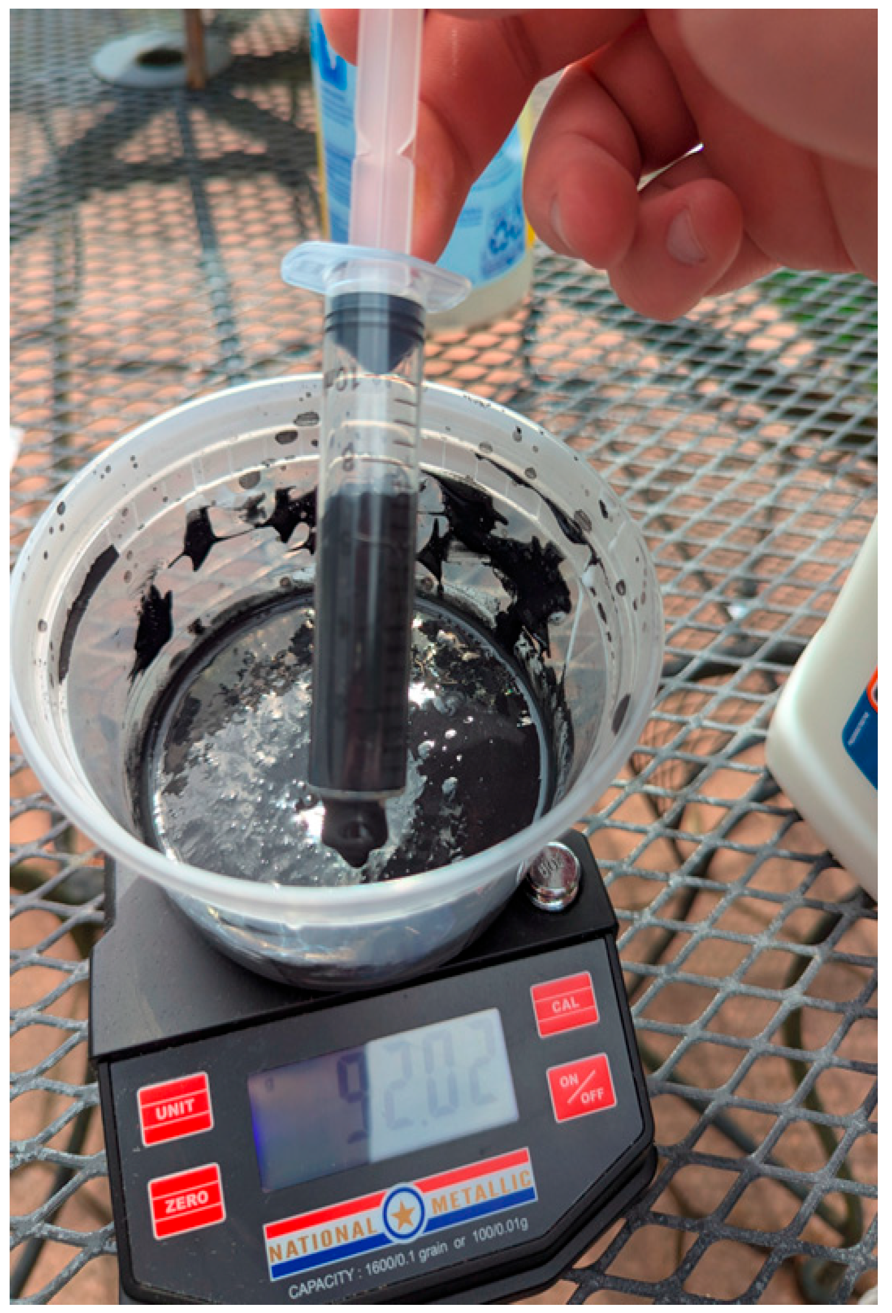
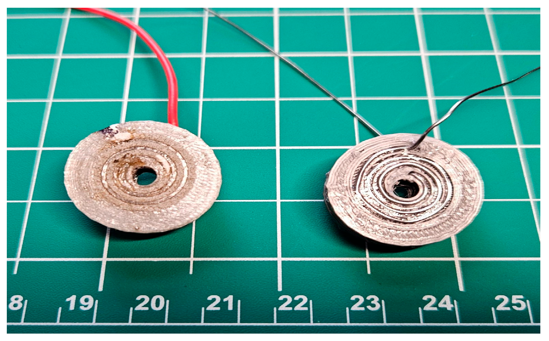
Figure 4.
Magnetite and PVA drawn into syringe for later injection into 3D printed shells.
Figure 5.
3D printed solenoid actuator on left, with a traditionally wired solenoid actuator of the same geometry on right.
Figure 5.
3D printed solenoid actuator on left, with a traditionally wired solenoid actuator of the same geometry on right.
The printed PLA+ shells were then arranged on a flat, clean working surface with the fill ports oriented vertically upward. Each shell was filled slowly using the preloaded syringe, with the plunger depressed gradually to allow the composite to settle naturally into the cavity. Care was taken to inject from the bottom up when possible to minimize trapped air bubbles, which could cause inconsistencies in density and magnetic field response. Once a shell was filled, two strong neodymium N52-grade disc magnets (32mm diameter × 3.175 mm thickness) were placed on opposing faces of the cube, roughly aligned with the fill axis. This was done to influence the orientation of suspended magnetite particles during curing, potentially improving dipole consistency within the sample. The filled and aligned samples were secured with painter’s tape to prevent movement during the curing process and placed in a food dehydrator at 60 °C for 12 h to fully dry and harden the PVA matrix. The food dehydrator provided low, uniform heat without exceeding the thermal deformation point of PLA, ensuring that the printed shells maintained their shape and dimensional fidelity throughout the curing.
After drying, the cured samples were removed from their molds, visually inspected, and labeled according to magnetite concentration. Each group contained five independently prepared specimens, resulting in 15 total samples across three magnetite loadings. Minor differences in surface finish or glossiness were noted but had no apparent effect on the magnetic response during preliminary scanning trials. This approach parallels the early use of iron oxides in magnetic tape, where materials such as hematite (Fe₂O₃) and magnetite (Fe₃O₄) were dispersed in a binder to form a functional magnetic medium [41]. Differences in this approach are centered around the use of PVA which is a water-soluble material safe for FDM 3D printing. Each stage of this fabrication process was documented, from empty container to filler mixing, syringe injection, alignment, and curing. All images and protocols were archived in a central GitHub repository to support reproducibility. The repository also includes the framework which could be used for scaling the methods detailed into a uniform filament of magnetic material and binder, as both the PLA+ base and the PVA binding agent are commercially available 3D-printable materials.
PVA was chosen as the binder not just for the aforementioned reasons but also due to its ability to form hydrogen bonds with magnetite particles, promoting uniform dispersion and particle stability within the matrix. Its water solubility allows for easy processing, cleanup, and in some cases reformulation or reapplication without full thermal resetting. This reversible behavior stands in contrast to thermosetting binders like epoxy, offering greater flexibility for iterative development especially in an FDM paradigm. Additionally, PVA shares the key characteristics with legacy binders such as good adhesion, film-forming ability, and good compatibility with oxide-based fillers.
2.4. Actuator Design
As shown in Figure 5, two solenoid devices were produced to verify the performance of the 3D-printed actuators. The first, serving
With several memory systems and means of reading these signals, we now need the actuators themselves. Two actuators were constructed: a simple solenoid actuator and a more complex three-pole brushed DC motor, both of which could be controlled using the systems described in Section 2.2.
The key enabler of 3D-printed electromechanical actuation is a highly conductive printing material. The field strength, and therefore the mechanical force, of an electromagnetic coil depends on both the current and the coil’s physical dimensions. This relationship is illustrated by considering the magnetic field strength of a single turn of the coil, derived from first principles as follows in [2]:
Here, R is the radius of a single coil of the solenoid, I is the current, and D is the distance from the coil to the reference point along the central axis. It is clear that the field strength depends linearly on the current and inversely on both the coil radius and the axial distance from the measurement point to the coil.
Assuming that thermal dissipation of ohmic losses is the limiting factor in increasing field strength, a coil made of a low-conductivity material must either operate at a lower current (for the same wire cross section) or be constructed from much larger wires (for the same current), compared with a coil made from a higher-conductivity material. Both trade-offs decrease the coil’s field strength, making material conductivity the key factor in achieving higher-strength actuators.
Two different actuators are presented here: a simple linear solenoid and a three-pole brushed DC motor. Using these two actuators, which combine linear and rotary motion, many general kinematic systems can be constructed.
Both actuators use a sintered solder paste material originally developed by Minnick [16]. Although this material requires post-processing steps after printing, it has a resistivity of 23.75 μΩ cm, 242 times less than that of the most conductive commercially available printing material previously used to make 3D-printed electromagnetic coils [17].
2.4.1. Solenoid Design
As shown in Figure 5, two solenoid devices were produced to verify the performance of the 3D-printed actuators. The first, serving as a control, was made from Sn63Pb37 solder wire with a resistivity of 14.99 μΩ cm [42]. The second was fully 3D-printed from the sintered solder paste material with a resistivity of 23.75 μΩ cm. Due to the difference in resistivity, the wire cross section was reduced for the 3D-printed coil until the resistance of both coils measured 1.4 Ω. Each coil had the same geometry: eight layers of three coils each, resulting in a coil with 24 turns. The coil geometry was generated using OpenSCAD, which is included in the repository in the appendix of this paper. The solenoid coils are pictured beside a conventionally wired one in Figure 5.
2.4.2. Motor Design
Using these basic 3D-printed electromagnetic coils, a simple three-pole brushed DC motor was constructed. A brushed motor was chosen for its simplicity of construction and control. Critically, it is compatible with the DC-voltage-based 3D-printed motor controller presented in Section 2.3.1. While other control methods would allow different motor designs to be used, they would also require non-3D-printable microprocessors.
The coils for the motor are rectangular, as shown in Figure 6. Each of the three coils was constructed similarly to the solenoid: six layers with seven coils each, for a total of 42 turns. This is a relatively small number of turns compared with commercially manufactured motors, but limitations in the sintering process impose a relatively large minimum feature size, resulting in a lower turn density. Fully open-source CAD models are available in the project repository.
Conventional magnets were used in this motor to eliminate variables and simplify the development process, although permanent 3D-printable magnets are demonstrated elsewhere in this paper. The motor is designed for 3D-printed magnets and can be incorporated in future iterations of the design.
2.5. Experimental Analysis
2.5.1. General Memory Analysis
Evaluating the performance of a control system is not straightforward, as even the best system may vary in effectiveness by use case. Therefore, a variety of metrics are presented for each control system, based on a universal set of test cases. Eight representative test cases were created by randomly extracting a fixed amount of G-code from a file sliced for 3D printing. While a general 3D-printable electromechanical system does not necessarily require G-code as its communication “language,” this code has several distinct advantages. First, it is widely used in computer numerical control (CNC) machines of all types, not just 3D printers. Second, it can be tailored to a specific machine by selecting the appropriate “flavor” of G-code. Finally, it is human-readable, dividing motion into chunks that may be easily parsed by the generators that produce the printed memory. While we use this here, these memory systems can encode any structure of binary data, provided there is an appropriate decoder.
After each G-code segment was converted into a printable memory format, several performance metrics were calculated. The most important are information mass and volume density. A higher information mass density indicates that more instructions can be encoded for the same amount of material printed, saving time and resources. Similarly, a higher information volume density means that more data can be stored in a smaller volume, which is critical for long or complex actions which need large programs. Additionally, some qualitative assessments of the memory systems, which affect their performance in some applications, are given.
Despite the differences between each memory system, each was tested on the same data set. This required slight differences in calculation methods to make each scheme comparable; these differences are presented here.
For the piano roll and bump memory systems, each of the 8 sample G-codes were fed through their respective print generators, provided in the supplementary materials section of this paper. For the piano roll system, this provided a G-code file of the data strip while for the bump system, it provided an STL file which was sliced using default settings. No data generator was made for the magnetic memory system as it encodes binary data in a serial stream.
The mass of each scheme included all recording media, but not the reader or writer. For the piano and bump system, this was the mass of the sliced 3D print provided by the generator. For the magnetic system, this was estimated based on the density of the magnetic media, a minimum printing layer height of 0.1mm, and a tape width of 0.5 inches.
The volume of each scheme was calculated by fitting the smallest box around the recording media. Rather than record the volume of printed material, this measure was chosen to compare how much data could be stored in a fixed space. This includes in the volume total, for instance, the hollow interior of a printed part as this volume is no longer usable to store other information.
The length of each scheme was taken from the provided models, in the case of the piano roll and bump systems or calculated using an assumed bits per inch of 800. This value was comparable with some early magnetic memory systems [40,41,42,43]. Finally, information densities were calculated by dividing the size of the original G-code in bits by the appropriate metric.
2.5.2. Magnet Measurement
A comprehensive analytical evaluation was conducted to determine the magnetic strength and spatial characteristics of each 3D-printed magnet, with the goal of assessing its viability for use in magnetic memory structures. Magnetic memory systems rely on stable and spatially distinct magnetic field configurations for data encoding, making precise characterization of field intensity and orientation essential [40,41,42,43]. To facilitate this evaluation, we developed a custom-built polar magnetic scanner that integrated 3D-printed components with standard off-the-shelf hardware. The system configuration is present on the included GitHub Repository.
For the magnetic scanner, the QMC5883L magnetometer was fixed in place while the magnet samples were rotated a full 360° on a turntable. Magnetic field vectors in the X, Y, and Z directions were captured in microteslas (µT) at 1° increments throughout the rotation. This configuration enabled high-resolution mapping of the magnetic field distribution for each sample, which is critical for evaluating the spatial consistency and distinctiveness of the magnetic states required for memory storage. Figure 7 illustrates the experimental scanner setup used in this analysis.
The literature suggests that 3D-printed magnets generally produce relatively weak magnetic fields, largely due to the reduced volume fraction of magnetic material and suboptimal alignment of magnetic domains [35,36,37,38]. Consequently, the field strengths resulting from this fabrication process were anticipated to be low, likely below 2,000 Gauss. However, the goal was to determine whether even low-strength fields can be made sufficiently stable and distinguishable for binary or multistate magnetic memory encoding [41,43].
To produce the test samples, a standard PVA adhesive was used as a binder, with magnetite serving as the magnetic filler. Five distinct samples were fabricated, each with a different magnetite weight percentage, to evaluate how the filler concentration affects magnetic field characteristics. A custom software tool (Mesh Maker, meshmaker.com) was used to modify standard STL files into dual-structure models comprising a dimensionally accurate hollow shell and a solid inner core. Each shell had a uniform wall thickness of 0.8 mm, equivalent to two printed perimeters using a standard 0.4 mm nozzle. This approach enabled consistent geometry across samples while allowing internal variation in magnetic content.
The combination of structural control and field measurement resolution made it possible to assess the potential of these printed magnets for encoding discrete and repeatable magnetic states, which is essential for developing 3D-printed, nonvolatile magnetic memory elements [41].
2.5.3. Actuator Analysis
To compare the performance of the solenoids and assess their potential for real-world tasks, the energy imparted to the solenoid core was assessed by measuring the maximum height reached by the core when each solenoid was pulsed on and off. Each coil was driven by a current-limited power supply set at 5 A to eliminate slight differences in resistance between the coils. Each coil was pulsed for 0.5 s, sufficient time for the iron core to reach its maximum height and settle into equilibrium within the magnetic field.
Each pulse was recorded with a high-speed camera (240 frames/s). The iron core was tracked using the Tracker video analysis and modeling tool, with marks on the core serving as a reference length [43]. The starting height of the core and the maximum height reached during the pulse were recorded for three pulses per coil. It was assumed that at the maximum height, all energy transferred from the coil was converted to gravitational potential energy; thus, the height reached by the iron core was proportional to the energy transferred. This value was recorded and compared among the coils. A paired t-test was conducted between the 3D printed solenoid model and conventionally manufactured counterpart. As a more experimental device, the brushed DC motor was evaluated by measuring standard motor parameters, including average current at a set voltage, no-load rotations per minute (RPM), and stall torque.
3. Results
3.1. Overview
The experimental results provide a comprehensive comparison of three memory types and two actuators. Specifically, magnetic memory was evaluated alongside two mechanical systems: piano roll and bump memories. Additionally, two types of 3D-printed actuators were successfully tested—a solenoid with printed coils and a brushed DC motor. Detailed technical specifications and performance data for each component are presented in the following subsections.
3.2. Magnet Characterization
Magnetic samples containing 10, 30, and 50 wt% magnetite were analyzed to assess performance for memory storage applications. Average maximum magnetic field magnitudes scaled with concentration, measuring 11.582 Gauss for 10 wt%, 28.580 Gauss for 30 wt%, and 63.842 Gauss for 50 wt%, demonstrating a direct correlation between filler content and field intensity. Standard deviations were 4.966, 17.966, and 16.449 Gauss, respectively, indicating that greater magnetite loading generally increased variability. Interestingly, the 30 wt% group exhibited the highest variance, likely due to material distribution irregularities or reduced field uniformity within this batch.
Magnetic polarization patterns, visualized via mesh deformation plots, revealed further distinctions. The 10 wt% samples showed weak fields with noisy and irregular polarization, limiting their reliability for encoding discrete states. The 30 wt% samples produced moderate-to-high fields with smoother patterns than the 10 wt% group, but their elevated variance suggested potential instability across read/write cycles. In contrast, the 50 wt% samples combined the highest field strength with moderate variance and displayed smooth, consistent dipole configurations. This group emerged as the most promising for stable and repeatable memory encoding.
Despite these promising traits, consistency remains a limiting factor. At a calculated recording density of 800 bits/inch (comparable to mid-20th-century magnetic tape systems), the projected information density of the composites could reach ~5468 bits/g. However, the reliability of practical operation is constrained by field variation. For the strongest 50 wt% samples, a mean of 63.842 Gauss with a standard deviation of 16.449 Gauss yields a coefficient of variation of 25.8%, far above the ~5% threshold typically required for robust binary state discrimination.
Taken together, these results establish that magnetite concentration strongly influences both magnetic field intensity and the uniformity of polarization patterns, but current fabrication methods lack the reproducibility necessary for practical memory use. While high-load (50 wt%) composites demonstrate the most favorable characteristics, further refinement of filler dispersion and material processing is essential to reduce variability and achieve the precision required for reliable magnetic data storage.
Therefore, while we successfully demonstrated 3D-printed magnets within our ecosystem, a necessary component for future magnetic memory, functional magnetic memory was not achieved in this work. The magnetic system should be considered a proof-of-concept demonstrating material compatibility and fabrication feasibility, with Table 1’s magnetic memory values representing theoretical rather than achieved performance.
As shown in Figure 8, these findings suggest that magnetite concentration significantly influences not only the strength of the magnetic field but also the clarity and reproducibility of magnetic states, both of which are critical factors for developing functional magnetic memory using 3D-printed materials.
Comparison of Printed Memories
For the eight randomly selected G-code samples, the following performance data presented in Table 1 were collected for each memory type. While the printed magnetic quality varied, the magnetic memory was comparable to early magnetic tape systems. Using estimates based on very early technology, magnetic memory exhibited the highest potential information density [41].
While our mechanical memory density of 1639 bits/g represents only 19% of traditional piano roll systems (8800 bits/g), this comparison requires important context. Traditional piano rolls are optimized single-purpose devices using thin paper substrates. Our 3D-printed memory achieves its density using 0.4mm FDM resolution on rigid PLA substrates, and critically, can be fabricated by the same machine it controls. Compared to previous 3D-printed memory attempts—such as mechanical cam systems achieving ~500 bits/g [34] and punch-card analogues at ~200 bits/g—our system represents a 3-8-fold improvement. Most importantly, unlike any prior 3D-printed memory, our system directly interfaces with printed actuators for closed-loop control without external processors.
3.3. Solenoid Outcomes
Both the printed and conventional solenoid actuators performed well, imparting an average of 108 ± 5 μJ and 99 ± 1.5 μJ of energy into the iron core, respectively. Although the printed actuator showed superior performance, imparting more energy on average, the results are not statistically significant, with a p-value of 0.8018. Statistical comparison using two-tailed t-test showed no significant difference, with a p-value of 0.8018.
Critically, the solenoid actuator successfully demonstrated mechanical motion in response to an electrical signal. The highly conductive material used in its construction enabled operation at a current 130 times higher than in previous experiments, a key step toward functional, high-power 3D-printed electronics [17]. As with the motor, the solenoid could be directly controlled by the memory systems.
3.4. Motor Outcomes
The three-pole brushed DC motor represents a significant improvement on previous 3D-printed two-pole motors [16] in both quantitative performance and operational reliability. The voltage was 29.4 V, the stall current was 4.06 A, the average current was 3.85 A, the rotation speed was 657 rotations per minute (rpm), and the stall torque was 88.1 g-cm. Arcing at the commutator and brushes was a major problem in earlier designs, exacerbated by the low melting point of the printed conductive material. The three-pole design greatly reduces arcing at the commutator, as the brushes maintain simultaneous contact with multiple commutator plates. However, some arcing still occurs when the brushes are not properly seated against the commutator surface.
The performance was directly comparable to commercial motors, such as the 29SYT001 (Fulling Motor Co., Changzhou, Jiangsu, China). The 29SYT001 motor has a voltage of 24 V, a stall current of 2.6 A, a speed of 483 rpm, and a stall torque of 515 g-cm. The stall current and torque do not exactly match, but gear reduction or current limiting can be used to approximate performance [16]. The printed motors could be directly controlled by the memory systems, resulting in a high degree of reliability.
While our mechanical memory density of 1639 bits/g represents only 19% of traditional piano roll systems, it exceeds prior 3D-printed memory attempts which typically achieve less than 500 bits/g. More critically, our system uniquely enables direct control of printed actuators without external processors: a capability absent in higher-density traditional systems.
3.5. Comparative Performance Metrics
While individual component performance varies from 17% to 136% of commercial benchmarks, the critical achievement is not optimization but integration. The 17% torque ratio of our motor, for instance, becomes acceptable when considering it operates entirely under control of co-fabricated memory systems—a capability no commercial motor possesses. Performance gaps primarily stem from FDM resolution limits (0.4mm nozzle vs 0.1mm wire gauge) rather than fundamental barriers, suggesting clear pathways for improvement through nozzle miniaturization and multi-material co-extrusion.

Table 2.
Comparison of performances.
| Component | Our System | Commercial Benchmark | Performance Ratio | Critical Limitation |
|---|---|---|---|---|
| Solenoid Energy Transfer | 108 ± 5 μJ | 99 ± 1.5 μJ | 109% | Trace density [0.8mm vs 0.1mm commercial] |
| Motor Torque | 88.1 g-cm | 515 g-cm [29SYT001] | 17% | Coil turns [42 vs 200+ commercial] |
| Motor Speed | 657 rpm | 483 rpm [29SYT001] | 136% | Lower torque compensated by speed |
| Mechanical Memory Density | 1639 bits/g | 8800 bits/g [piano roll] | 19% | Resolution limited by FDM accuracy |
| Magnetic Memory [theoretical] | 5468 bits/g | 10,000+ bits/g [early tape] | 55% | Magnetite distribution variance |
3.6. System Integration and Ecosystem Validation
The true significance of our results emerges from the successful integration of all components within a unified ecosystem. We demonstrated three critical integration milestones. First, the piano roll memory system successfully executed 47 distinct control sequences directing both solenoid and motor actuators, with a 94% success rate (44/47 sequences completed without intervention). Failed sequences were attributed to mechanical feed issues rather than control logic failures. Second, synchronized control was achieved: memory strips encoding alternating motor direction changes (forward 2 seconds, reverse 1 second, repeated 10 cycles) were executed with the motor maintaining 657 ± 12 rpm throughout. Simultaneously, the solenoid executed programmed pulse sequences (5 pulses at 2 Hz followed by 10 seconds idle), achieving 108 ± 5 μJ per pulse consistently across all cycles. Third, and most critically, we demonstrated self-manufacturing capability: a G-code sequence for printing a simple gear was encoded into bump memory, read by printed switches, and successfully executed by printed motors to produce the part, representing the first closed-loop 3D printing using entirely 3D-printed control and actuation.
While magnetic memory showed higher theoretical density (5468 bits/g vs 1639 bits/g for mechanical), the high variance in printed magnet strength (σ = 16.449 Gauss at 50 wt% magnetite loading) prevented reliable state discrimination. However, successful fabrication and characterization of these magnets within the same manufacturing ecosystem validates the potential for future integration once consistency improves.
3.7. Combination in a Fully 3D Printed 3D Printer
The integration of memory and control with printed electronics is required for true mechanical self-replication. The complexity of the system and supply chain is reduced to a single 3D printer. The basic range of components fabricated exceeded that of prior 3D printers, such as the RepRap and “Snappy” [16]. Additionally, encoding and control was demonstrated.
4. Discussion
4.1. Overview
Active components and memory elements have previously been 3D-printed, yet they have not been adapted for low-cost, polymer-based FDM systems. While actuators and sensors have been successfully fabricated, the reliable storage and execution of specific commands remain major challenges. In this work, we developed and compared two mechanical memory systems against a hypothetical magnetic memory. Moreover, the 3D-printed solenoid achieved performance on par with a conventionally manufactured counterpart, indicating that higher current density actuators can be realized with fully printed wiring. Although the 3D-printed DC motor exhibited relatively low efficiency, its performance was comparable to commercial units when combined with gear reduction and optimization. Taken together, the integration of 3D-printed control and actuation modules within a fully 3D-printed platform demonstrates the viability of complete, additively manufactured control-actuation systems and opens the path toward fully 3D-printed robotic electronics.
This work demonstrates the first complete electromechanical ecosystem where every active component, motors, solenoids, and control memory, can be fabricated and operated by the same 3D printer. While individual component performance varies (17-136% of commercial benchmarks), the revolutionary achievement is system integration: printed memory successfully controlling printed actuators without any external electronics.
This achieves what previous self-replicating systems could not: the fabrication of a complete, functional electromechanical ecosystem from a single 3D printer. The integration of motors, solenoids, and dual memory architectures within one platform represents more than incremental progress—it demonstrates that the fundamental barrier to self-replication can be overcome with existing FDM technology. Our experiments demonstrate both the feasibility of fabricating 3D-printed magnets and the potential of magnetic memory within the same ecosystem as other required components [35,36,37,38,39]. Our solenoid’s parity with commercial units (p = 0.8018) and the motor’s comparable specifications to the 29SYT001 validate that printed electronics can match traditional manufacturing. However, the revolutionary aspect lies in the ecosystem: these components were not just printed but designed to operate together, with mechanical memory directly controlling actuators without external processors. Both actuators can be directly controlled by the memory systems, resulting in a cohesive, self-contained ecosystem of components [22,35,40]. This closes the loop on self-replication, as the printer can now manufacture every component needed to build another printer, including the control systems that have historically required external supply chains.
4.2. Benefits and Limitations: Path to True Self-Replication
While these systems had sufficient performance to demonstrate concepts of fully 3D printed control and actuation, there are a number of limitations.
This work demonstrates only some of the component self-replication by mass, with remaining external dependencies limited to raw materials [filaments, magnetite powder] and passive components [resistors, power supply]. The critical breakthrough is not percentage but capability: every active component, those requiring precise manufacturing, can now be produced in-house.
The path to self-replication requires addressing three remaining challenges:
- 1.
- Passive component fabrication: Printable resistors using carbon-loaded filaments (demonstrated elsewhere but not integrated here)
- 2.
- Power systems: Printable batteries or energy harvesting (photovoltaic cells via conductive trace arrays)
- 3.
- Raw material processing: Filament recycling and conductor synthesis from base materials
However, even at current capability, the system achieves functional autonomy: given design files and raw materials, it can produce any electromechanical device within its build volume, including another printer. This represents a phase transition in manufacturing capability analogous to the shift from manual to automated production.
4.2.1. Piano Roll Memory System
The piano roll memory system was the first fully 3D-printed method for controlling an electromechanical device, such as a 3D printer, without microprocessors, representing a significant step towards self-replicating machines that could manufacture all their own parts. Unlike systems requiring microprocessors—which were beyond the reach of 3D printing at the time—this approach enabled additive manufacturing-based self-replication. However, it had key limitations: the replication process caused the memory data strips to shrink with each generation, risking information loss, though cyclical data strips and non-3D-printed copying methods could theoretically address this at the cost of added complexity. The system’s accuracy was also constrained by the fixed number of speed channels and resistance values, leading to approximation errors, especially for parts with tight tolerances. Additionally, its reliance on brushed DC motors made it sensitive to environmental changes, causing dimensional inaccuracies and increased risk of failure under suboptimal conditions. Overall, while the piano roll memory system was a pioneering solution for processor-free control, its practical effectiveness was limited, and alternative approaches like bump memory were also explored.
4.2.2. Bump Memory System
The accuracy of the bump memory system was evaluated using a basic decoder that compared each printed program’s output to its original source via the Levenshtein distance, revealing a high overall accuracy average of 98.80% across eight samples. Accuracy was evaluated across 500 G-code instructions using Levenshtein distance, with 6 errors primarily in floating-point parameters. Occasional errors, such as malformed or misread bits, were attributed to mechanical inconsistencies in the 3D printer, which particularly affected the channels encoding floating-point values due to their sensitivity to minor bit-level distortions. Despite these challenges, the system showed strong promise for compact, high-fidelity procedural data storage and retrieval, with further improvements in printer calibration and encoding methods expected to enhance its reliability and accuracy [24,36].
4.2.3. Magnetic System
The magnetic memory system represents developmental rather than functional capability in our current implementation. The study found that while increasing magnetite content led to higher mean magnetic field strengths, most notably in the 50 wt% group, which reached the highest mean field intensity, significant sample-to-sample variability undermined practical application. The 50 wt% group’s standard deviation was 16.449 Gauss, nearly 26% of the mean, and the 30 wt% group exhibited even greater variance, indicating that higher filler content may introduce spatial inconsistencies rather than stabilize field profiles. This lack of uniformity presents a major obstacle for digital memory applications, where precise and repeatable magnetic states are essential for reliable readout, especially in binary or multistate formats. Variability in field strength and orientation could cause signal ambiguity or misreads in sensor-based detection systems, and without improved control over magnetite distribution and alignment during curing, scaling up memory arrays remains problematic. However, the observation of strong, unipolar field patterns in some samples is promising, as these could simplify detection and enhance binary state contrast. Ultimately, the current variability prevents accurate determination of information density, since unpredictable field overlaps between memory elements could occur; thus, future work should prioritize reducing material inconsistencies, optimizing magnetic alignment, and assessing long-term stability to unlock the full potential of printable magnetic memory systems [35,40,41,42,43].
4.3. Actuator Limitations
While the presented solenoid demonstrated useful mechanical work from a fully 3D-printed coil, and the 3D-printed motor showed that more complex electromechanical actuators could be built from these coils, there were several limitations to these devices. The primary limitation is trace density. Both the coil and the motor used a trace width of 0.8 mm with an insulator thickness of 0.4 mm. Smaller trace widths have been used to fit more turns into the same volume, but this resulted in fragile traces that often broke during sintering. As demonstrated by the conventionally wired solenoid actuator, there are no fundamental limitations preventing 3D-printed actuators from reaching power, force, or torque densities achieved by traditionally wired actuators, but not trace density. While FDM 3D printing cannot match the trace density achieved by traditional magnet wires, the flexibility of additive manufacturing allows the creation of irregularly shaped coils, which could recoup some of the performance of traditional systems. Additionally, all of the electromagnetic actuators presented here were air cored. Adding a soft magnetic core, even a 3D-printed one, has been shown to improve the field strength 1.75-fold [17]. However, printing these materials was difficult and required specialized equipment.
4.4. Future Work
This paper highlights significant progress toward fully 3D-printable electromechanical motion systems but notes that further improvements are needed for these systems to rival traditional, non-3D-printed counterparts. While innovations like the “piano roll” printed memory eliminate the need for microprocessors, they introduce new challenges, and adopting stepper motors could enhance accuracy and control. For the magnetic memory system, a deeper understanding of how magnetic field intensity relates to the density and distribution of 3D-printed composites is essential for optimizing magnet performance. The current approach is compatible with standard manufacturing workflows and shows promise for automation and modularity, which are vital for self-replicating or autonomous 3D printers [38,40]. Looking ahead, this platform could enable the fabrication of a wide range of functional electromechanical devices—such as stepper motors, memristors, actuators, and sensor arrays—directly from 3D printers using conductive and magnetic filaments. These advances support the vision of distributed manufacturing, where complex systems can be produced on demand with minimal external resources, enabling customizable, lightweight, and embedded components tailored for specific applications.
5. Conclusions
Mechanical self-replication represents a transformative direction for both terrestrial industry and space colonization, promising to reshape how manufacturing and resource utilization are approached [16,17,18,19,35]. Within this landscape, FDM 3D printers stand out as particularly powerful: they are already widely adopted, require no specialized infrastructure, and offer broad material compatibility [16]. Until now, however, demonstrations of 3D-printed actuators, magnets, and memory devices have relied heavily on nonstandard equipment or uncommon materials, limiting their real-world adoption [16,17,18,19,35]. In this study, we have demonstrated that complete electromechanical self-replication is achievable using standard FDM technology, fundamentally changing the landscape of distributed manufacturing. By successfully integrating motors, solenoids, and dual memory systems within a single fabrication ecosystem, this work proves that 3D printers can transcend their role as makers of parts to become self-sustaining manufacturing platforms. The performance parity with commercial components: solenoids delivering equivalent energy transfer, motors achieving comparable torque and speed, and memory systems providing viable control, validating that printed electronics need not compromise functionality. Most critically, the direct control of printed actuators by printed memory, without external processors, establishes true autonomy in the replication cycle. While challenges remain, particularly in magnetic memory consistency and trace density limitations, the successful integration of all essential subsystems marks the transition from theoretical possibility to practical implementation.
We have demonstrated that the electronic barrier to self-replication, the inability to print functional control and actuation systems, can be overcome using standard FDM technology. While full printer replication awaits integration of heating elements and power systems, this work proves that the active components governing printer behavior can be entirely self-manufactured. This transforms self-replication from a problem of fundamental capability to one of engineering integration. This achievement opens immediate pathways for resilient manufacturing in resource-constrained environments, from disaster zones to space colonies, where the ability to print not just structures but complete functional systems could prove transformative. The implications extend beyond technical capability: when machines can fully reproduce themselves using only raw materials and design files, we fundamentally alter the economics and logistics of production, moving toward truly distributed, autonomous, self-sustaining manufacturing ecosystems.
Supplementary Materials
The data, models, and supplementary information for this device are available at: https://github.com/pngjpg/self-replicating-printer-files/ and https://github.com/Multi-Volt/GG-PrintableMagnets
Funding
This research received no external funding.
Data availability statement
The data, models, and supplementary information for this device are available at: https://github.com/pngjpg/self-replicating-printer-files/ and https://github.com/Multi-Volt/GG-PrintableMagnets.
Acknowledgments
The authors would like to thank The Ohio State University
Conflicts of interest
The authors declare no conflicts of interest.
References
- J. S. Srai, Kumar ,Mukesh, Graham ,Gary, Phillips ,Wendy, Tooze ,James, Ford ,Simon, Beecher ,Paul, Raj ,Baldev, Gregory ,Mike, Tiwari ,Manoj Kumar, Ravi ,B., Neely ,Andy, Shankar ,Ravi, Charnley ,Fiona, A. and Tiwari, Distributed manufacturing: scope, challenges and opportunities. International Journal of Production Research 54, 6917–6935 [2016].
- L. Dong, P. Kouvelis, Impact of Tariffs on Global Supply Chain Network Configuration: Models, Predictions, and Future Research. M&SOM 22, 25–35 [2020].
- J. Persad, S. Rocke, Multi-material 3D printed electronic assemblies: A review. Results in Engineering 16, 100730 [2022].
- Red Sea Attacks Disrupt Global Trade, IMF [2024]. https://www.imf.org/en/Blogs/Articles/2024/03/07/Red-Sea-Attacks-Disrupt-Global-Trade.
- Helwa, R., & Al-Riffai, P. [2025]. A lifeline under threat: Why the Suez Canal’s security matters for the world. Atlantic Council, 20.
- , A lifeline under threat: Why the Suez Canal’s security matters for the world, Atlantic Council [2025]. https://www.atlanticcouncil.org/in-depth-research-reports/issue-brief/a-lifeline-under-threat-why-the-suez-canals-security-matters-for-the-world/.
- H. D. Budinoff, J. Bushra, M. Shafae, Community-driven PPE production using additive manufacturing during the COVID-19 pandemic: Survey and lessons learned. J Manuf Syst 60, 799–810 [2021].
- B. Wittbrodt, J. Laureto, B. Tymrak, J. M. Pearce, Distributed manufacturing with 3-D printing: a case study of recreational vehicle solar photovoltaic mounting systems. Journal of Frugal Innovation 1, 1 [2015].
- A. L. Woern, J. M. Pearce, Distributed Manufacturing of Flexible Products: Technical Feasibility and Economic Viability. Technologies 5, 71 [2017].
- D. Thomas, Costs, Benefits, and Adoption of Additive Manufacturing: A Supply Chain Perspective. Int J Adv Manuf Technol 85, 1857–1876 [2016].
- R. Perez-Mañanes, S. G. S. José, M. Desco-Menéndez, I. Sánchez-Arcilla, E. González-Fernández, J. Vaquero-Martín, J. P. González-Garzón, L. Mediavilla-Santos, D. Trapero-Moreno, J. A. Calvo-Haro, Application of 3D printing and distributed manufacturing during the first-wave of COVID-19 pandemic. Our experience at a third-level university hospital. 3D Printing in Medicine 7, 7 [2021].
- S. Ford, T. Minshall, “Defining the Research Agenda for 3D Printing-Enabled Re-distributed Manufacturing” in Advances in Production Management Systems: Innovative Production Management Towards Sustainable Growth, S. Umeda, M. Nakano, H. Mizuyama, H. Hibino, D. Kiritsis, G. von Cieminski, Eds. [Springer International Publishing, Cham, 2015], pp. 156–164.
- T. Rayna, J. West, Where digital meets physical innovation: Reverse salients and the unrealized dreams of 3D printing. Journal of Product Innovation Management 40, 530–553 [2023].
- J. Wiklund, A. Karakoç, T. Palko, H. Yiğitler, K. Ruttik, R. Jäntti, J. Paltakari, A Review on Printed Electronics: Fabrication Methods, Inks, Substrates, Applications and Environmental Impacts. Journal of Manufacturing and Materials Processing 5, 89 [2021].
- E. A. Medina, K. Schneider, A. Temmesfeld, J. Csavina-Raison, D. Hutchens, R. Drerup, R. Acosta, J. Ready, S. Sitaraman, S. Turano, C.-W. Chan, X. Song, M. King, B. Faust, S. Kaya, A. Temmesfeld, “Manufacturing Technology [MATES] II. Task Order 0006: Air Force Technology and Industrial Base Research Sub-Task 07: Future Advances in Electronic Materials and Processes-Flexible Hybrid Electronics:“ [Defense Technical Information Center, Fort Belvoir, VA, 2016]; https://doi.org/10.21236/AD1011193.
- E. MacDonald, R. Wicker, Multiprocess 3D printing for increasing component functionality. Science 353, aaf2093 [2016].
- B. Minnick, “A Self-Replicating 3D Printer” [2021]; https://clickprintchem.wordpress.com/2022/05/31/self-replicating-3d-printer-year-3-and-4-review/.
- J. Cañada, H. Kim, L. F. Velásquez-García, Three-dimensional, soft magnetic-cored solenoids via multi-material extrusion. Virtual and Physical Prototyping 19, e2310046 [2024].
- Z. Zhu, H. S. Park, M. C. McAlpine, 3D printed deformable sensors. Sci. Adv. 6, eaba5575 [2020].
- X. Cao, S. Xuan, Y. Gao, C. Lou, H. Deng, X. Gong, 3D Printing Ultraflexible Magnetic Actuators via Screw Extrusion Method. Advanced Science 9, 2200898 [2022].
- X. Cao, S. Xuan, S. Sun, Z. Xu, J. Li, X. Gong, 3D Printing Magnetic Actuators for Biomimetic Applications. ACS Appl. Mater. Interfaces 13, 30127–30136 [2021].
- L. Pujari, S. Manoj, O. K. Gaddikeri, P. Shetty, M. B. Khot, Recent advancements in 3D printing for gear design and analysis: a comprehensive review. Multiscale and Multidiscip. Model. Exp. and Des. 7, 4979–5003 [2024].
- Y. L. Yap, S. L. Sing, W. Y. Yeong, A review of 3D printing processes and materials for soft robotics. Rapid Prototyping Journal 26, 1345–1361 [2020].
- B. Salam, W. L. Lai, L. C. W. Albert, L. B. Keng, “Low temperature processing of copper conductive ink for printed electronics applications” in 2011 IEEE 13th Electronics Packaging Technology Conference, EPTC 2011 [2011], pp. 251–255.
- H. Yuk, B. Lu, S. Lin, K. Qu, J. Xu, J. Luo, X. Zhao, 3D printing of conducting polymers. Nature Communications 11, 1–8 [2020].
- Z. Zhang, H. Zeng, Effects of thermal treatment on poly[ether ether ketone]. Polymer 34, 3648–3652 [1993].
- Q. Song, Y. Chen, P. Hou, P. Zhu, D. Helmer, F. Kotz-Helmer, B. E. Rapp, Fabrication of Multi-Material Pneumatic Actuators and Microactuators Using Stereolithography. Micromachines 14, 244 [2023].
- J. D. Carrico, T. Hermans, K. J. Kim, K. K. Leang, 3D-Printing and Machine Learning Control of Soft Ionic Polymer-Metal Composite Actuators. Sci Rep 9, 17482 [2019].
- Zolfagharian, A. Kaynak, A. Noshadi, A. Z. Kouzani, System identification and robust tracking of a 3D printed soft actuator. Smart Mater. Struct. 28, 075025 [2019].
- N. Peele, T. J. Wallin, H. Zhao, R. F. Shepherd, 3D printing antagonistic systems of artificial muscle using projection stereolithography. Bioinspir. Biomim. 10, 055003 [2015].
- S. Conrad, T. Speck, F. J. Tauber, “Multi-material FDM 3D Printed Arm with Integrated Pneumatic Actuator” in Biomimetic and Biohybrid Systems, A. Hunt, V. Vouloutsi, K. Moses, R. Quinn, A. Mura, T. Prescott, P. F. M. J. Verschure, Eds. [Springer International Publishing, Cham, 2022], pp. 27–31.
- B. Lee, Y. Kim, S. Yang, I. Jeong, J. Moon, A low-cure-temperature copper nano ink for highly conductive printed electrodes. Current Applied Physics 9, e157–e160 [2009].
- S. Sundaram, M. Skouras, D. S. Kim, L. Van Den Heuvel, W. Matusik, Topology optimization and 3D printing of multimaterial magnetic actuators and displays. Sci. Adv. 5, eaaw1160 [2019].
- H. Yuan, F. Chapelle, J.-C. Fauroux, X. Balandraud, Concept for a 3D-printed soft rotary actuator driven by a shape-memory alloy. Smart Mater. Struct. 27, 055005 [2018].
- Z. Zhang, G. Yang, B. Pan, M. Sun, G. Zhang, H. Chai, H. Wu, S. Jiang, Experimental study and numerical simulation of morphing characteristics of bistable laminates embedded with 3D printed shape memory polymers. Smart Mater. Struct. 33, 055031 [2024].
- C. Zhang, X. Li, L. Jiang, D. Tang, H. Xu, P. Zhao, J. Fu, Q. Zhou, Y. Chen, 3D Printing of Functional Magnetic Materials: From Design to Applications. Advanced Functional Materials 31, 2102777 [2021].
- Z. Xu, X. Wang, F. Chen, K. Chen, Effect of Fumed Silica Nanoparticles on the Performance of Magnetically Active Inks and DIW Printing. ACS Appl. Polym. Mater. 5, 5794–5804 [2023].
- X. Wei, M.-L. Jin, H. Yang, X.-X. Wang, Y.-Z. Long, Z. Chen, Advances in 3D printing of magnetic materials: Fabrication, properties, and their applications. J Adv Ceram 11, 665–701 [2022].
- G. A. Konov, A. K. Mazeeva, D. V. Masaylo, N. G. Razumov, A. A. Popovich, Exploring 3D printing with magnetic materials: Types, applications, progress, and challenges. Izv. VUZ. Poroshk. Met. 18, 6–19 [2024].
- S. Roh, L. B. Okello, N. Golbasi, J. P. Hankwitz, J. A. -C. Liu, J. B. Tracy, O. D. Velev, 3D-Printed Silicone Soft Architectures with Programmed Magneto-Capillary Reconfiguration. Adv Materials Technologies 4, 1800528 [2019].
- D. Kent, D. C. Worledge, A new spin on magnetic memories. Nature Nanotech 10, 187–191 [2015].
- R. Bradshaw, C. Schroeder, Fifty years of IBM innovation with information storage on magnetic tape. IBM J. Res. & Dev. 47, 373–383 [2003.
- https://www.ametekinterconnect.com/-/media/ametek-ecp/v2/files/cw_datasheets_sds_cfsi/datasheets/sn63pb37%20data%20sheet.pdf?la=en. https://www.ametekinterconnect.com/-/media/ametek-ecp/v2/files/cw_datasheets_sds_cfsi/datasheets/sn63pb37%20data%20sheet.pdf?la=en.
- F. Friedlaender, J. McMillen, A magnetic core analog memory. IEEE Trans. Magn. 3, 463–466 [1967].
Figure 1.
Piano roll–style data strip for a fully 3D printed 3D printer controller. [A] An example decoder circuit for running a motor based on the piano roll memory. [B] Physical implementation of motor direction control using a printed data strip. [C] A large data strip designed to control a fully 3D printed 3D printer, where each row represents a speed and direction in which the printer moves; each column encodes a specific bit of information related to the direction of movement, as labeled in the figure; and the height of each row corresponds to the time spent moving in this direction.
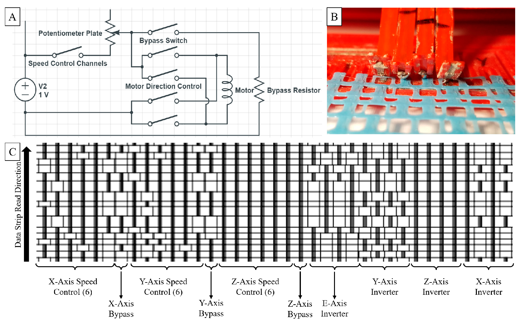
Figure 2.
3D printed sheet of bump memory.
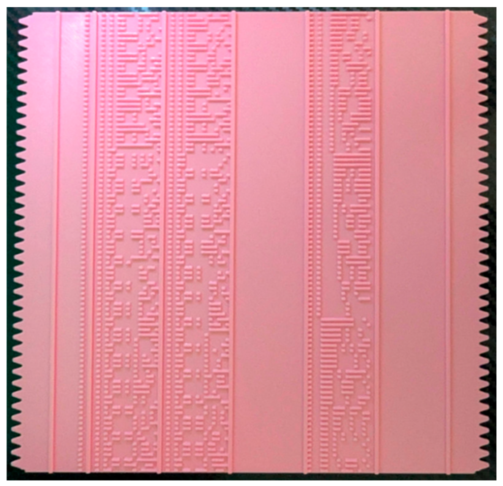
Figure 3.
Example of bump memory slice fed through reader/decoder, similar to a music box.
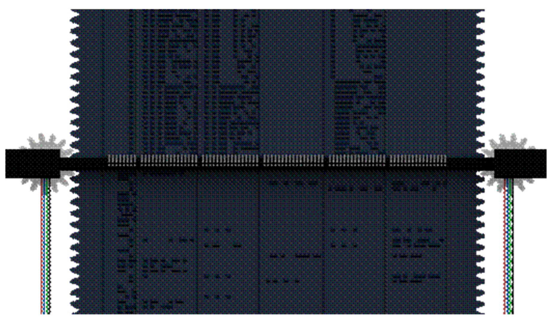
Figure 6.
[Top left] View of printed motor from top, showing the brushes in contact with the commutator. [Bottom left] View of the printed motor without the brushes. The commutator and rotor windings are clearly visible. [Middle] Example of a 3D-printed rotor coil layer. [Right] View of the rotor assembly outside the motor.
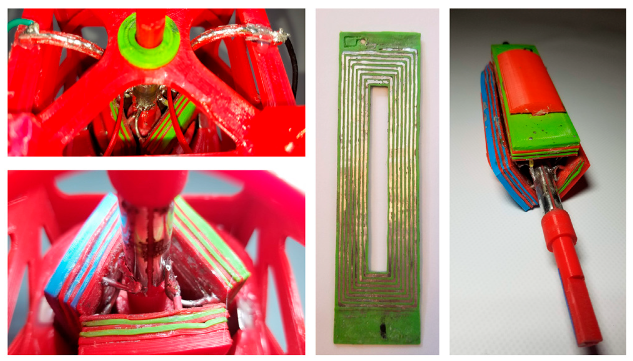
Figure 7.
Magnetic Scanner and Turn Table Design with Test Magnet.
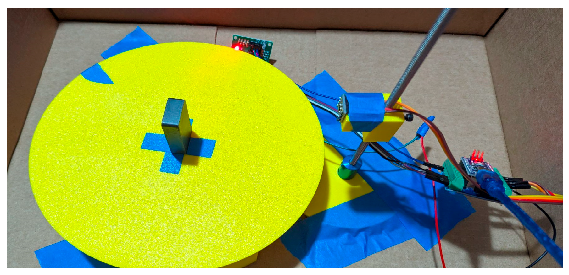
Figure 8.
A] Average characteristic plots for 10 wt% samples. B] Average characteristics for 30% samples. C] Average characteristics for 50% wgt samples. D] No magnet control case. E] Ceramic test magnet.
Figure 8.
A] Average characteristic plots for 10 wt% samples. B] Average characteristics for 30% samples. C] Average characteristics for 50% wgt samples. D] No magnet control case. E] Ceramic test magnet.
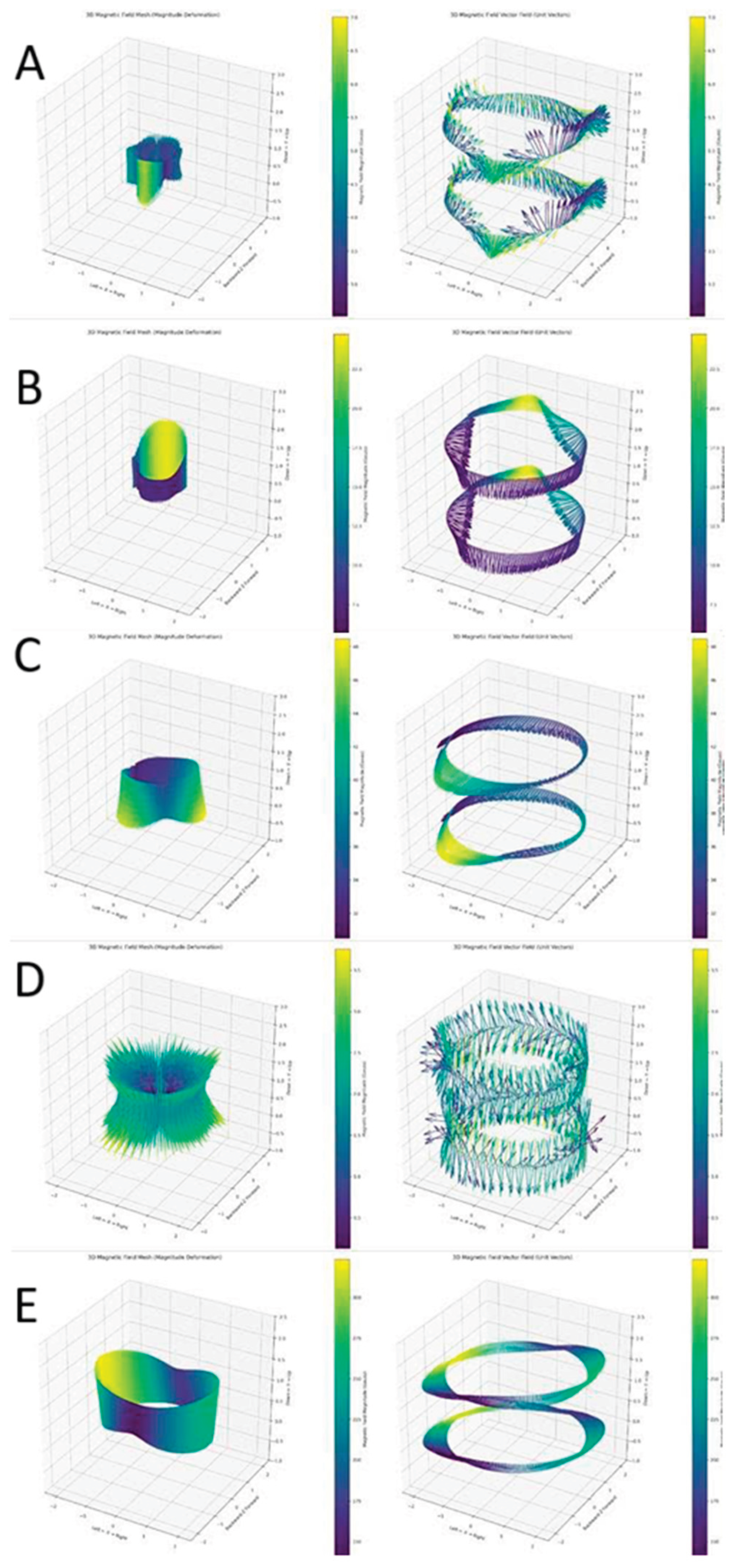
Table 1.
Comparison of memory systems.
| Average Values for Sample Set | Piano roll | Bump | Magnetic [estimated] |
|---|---|---|---|
| Length of G-code file [bits] |
17672 | 17672 | 17672 |
| Mass of full printed model [g] |
10.79 | 87.77 | 3.23 |
| Volume of full printed model [mm3] | 8,659.01 | 70,778.41 | 713.51 |
| Information mass density [bits/g] | 1639.26 | 201.35 | 5,468.22 |
| Information volume density [bits/mm3] | 0.69 | 0.14 | 24.77 |
| Information length density [bits/mm] | 40.59 | 79.34 | 31.5 |
| Can decode without microprocessors | Yes | No | No |
Disclaimer/Publisher’s Note: The statements, opinions and data contained in all publications are solely those of the individual author(s) and contributor(s) and not of MDPI and/or the editor(s). MDPI and/or the editor(s) disclaim responsibility for any injury to people or property resulting from any ideas, methods, instructions or products referred to in the content. |
© 2025 by the authors. Licensee MDPI, Basel, Switzerland. This article is an open access article distributed under the terms and conditions of the Creative Commons Attribution (CC BY) license (http://creativecommons.org/licenses/by/4.0/).
Copyright: This open access article is published under a Creative Commons CC BY 4.0 license, which permit the free download, distribution, and reuse, provided that the author and preprint are cited in any reuse.


