
Submitted:
17 June 2025
Posted:
19 June 2025
You are already at the latest version
Abstract
This paper catalogues a series of experiments we conducted to explore how to 3D print a DC electric motor. The individual parts of the electric motor were 3D printed but assembled by hand. First, we focused on the rotor with soft magnetic properties for which we adopted ProtoPastaTM which is a commercial off-the-shelf PLA filament incorporating iron particles. Second, we focused on the stator permanent magnets which were 3D printed through binder jetting. Third, we focused on the wire coils for which we adopted a form of laminated object manufacture of copper wire. The chief challenge was in 3D printing the coils because the winding density is crucial to the performance on the motor. We have demonstrated that DC electric motors can be 3D printed as assembled into a functional system. Although the performance was poor due to the wiring problem, we showed that the other 3D printing processes were consistent with high performance. Nevertheless, we demonstrated the principle of 3D printing electric motors. We regard this as a significant step towards implementing universal construction and, by proxy, self-replicating machines.
Keywords:
additive manufacturing
; universal constructor
; 3D printed motor
; self-replicating machines
1. Introduction
We are interested in building a universal constructor - a machine that, given the appropriate resources (material, energy and information), can construct any machine, including a copy of itself. The key to the universal constructor to exploit its versatility through its reconfigurability [6]. According to von Neumann [1], an abstract self-replicating machine comprises four functional systems: (A) a constructing arm (modelled as a robotic arm) that builds any machine specified by a program of instructions D; (B) a copying machine that can copy the program of instructions D; (C) a universal computing machine (modelled as a set of logic gates) that controls A by reading D for implementation and B for reading D for copying; (D) a program of instructions that may specify any machine including itself (A+B+C), i.e. a self-replicating machine. From von Neumann’s model, universal construction is a sufficient (but not necessary [2]) condition for self-replication. The universal constructor is, in essence, a set of robotic machines that manipulate its environment according to its instructions., i.e. the universal constructor constitutes a suite of robotic machines to convert raw material into specified robotic products that may include load-haul-dumpers, conveyors, ball mills, pumps, 3D printers, manipulators, etc. All the major physical acquisition and processing techniques required to convert raw material into products require actuators. Other than structure, the essence of all these robotic machines are mechatronic components – sensors, actuators and control systems. They are kinematic machines in that they are different kinematic configurations of motors each controlled by electronic circuits using feedback from sensors. Universal construction implies the automatic construction of robotic machines of production from raw material. A key component of universal construction is additive manufacturing (colloquially, 3D printing) which is capable of manufacturing highly sophisticated structures. To demonstrate that 3D printing constitutes universal construction, we must be able to 3D print the mechatronic triad components of robotics – actuators, sensors and controllers, i.e. 3D print robotic machines of any kinematic configuration. One such configuration is the cartesian robot of which the 3D printer is a type.
Figure 1 is a schematic that encapsulates the critical importance of electric motors and their controllers to the self-replication process (assumed to be implemented on the Moon [3]). The red arrows follow a production sequence: a rover with a scoop to excavate resources which are then processed mechanically and then (electro)chemically into feedstock that is 3D-printed. From this, the 3D printer(s) prints mechatronic components (represented here as an electric motor and an analogue neural network controller circuit). In its universal construction capacity, these comprise crucial components of any product machine, in this case, a small spacecraft with avionics and reaction wheels. The yellow arrows indicate that the motor and electronics are central components to its production machines – rover vehicle and its outboard equipment, mechanical processing/beneficiation, pumps to drive unit chemical processors and the 3D printer itself plus any other associated fabrication machines. The centrality of motor systems to the universal constructor/self-replicating machine is clear.
2. Additive Manufacturing
We are currently investigating the use of 3D printing (additive manufacturing) to convert the materials into useful products to demonstrate that manufactured parts can be built using a short processing sequence from raw material to final product. A central component of the universal constructor (and, by implication, the self-replicator) is a generalised additive manufacturing facility representing a versatile, efficient and powerful technique of manufacture [4]. Additive manufacturing (colloquially, 3D printing) is different to traditional subtractive manufacturing such as casting, forging, turning, milling, etc. It can manufacture complex geometries in a single location, unattainable through milling or other methods (Figure 2). 3D printing employs zero tooling and generates very little material waste compared with traditional subtractive machining. 3D printing technology aids in observing the matter, energy and information closure constraint between generations necessary for self-replicating systems [5]. To ensure maximum efficiency of the universal constructor, our intent is to minimise non-3D printing processes that impose significant infrastructure and energy costs, e.g. casting into moulds, forging with compressive dies, joining activities, etc. The RepRap 3D printer is an exemplar of an extrusion-based 3D printer in that it was capable of manufacturing some of its own structural (plastic) parts [4], i.e. partially self-replicating (Figure 2).
The RepRap 3D printer, like many 3D printing machines, is in essence a cartesian robot, and, indeed, the universal constructor has been envisaged as a cartesian robot assembler [7]. The cartesian (or delta) form of 3D printer may be converted into such an assembling system by replacing the 3D printing nozzle with a three degree-of-freedom wrist. Self-replication of a 3D printer requires the ability to 3D print all the parts that constitute itself. All robotic machines are in essence kinematic configurations of feedback-controlled actuators, the 3D printer being a cartesian configuration of DC electric motors.
Our hypothesis is that if we can 3D print an electric motor, we have progressed significantly towards a universal construction capability. A major leap towards such a universal constructor would be a demonstration that motors, electronics and sensors can be 3D printed within a single module of a self-assembling system [8]. In-situ manufacture of robotic systems requires the manufacture of electric motors, electronics and sensors. A complete motor system comprises motor, gearing, sensors and controller. The universal constructor is a robotic system implying that realisation of the self-replicating machine requires self-construction of mechatronic components from feedstocks. Here, we shall consider only electric motors – sensors and computational electronics as the second and third components of the mechatronic triumvirate are considered elsewhere [9,10]. We briefly review actuators and attempts to 3D print them, primarily as smart materials, and find that DC electric motors have yet to be 3D printed in their entirety until the work presented here.
There are a multitude of options for creating 3D printed actuators. Rigid/flexible polymers can be 3D printed to form fluidic channels for hydraulic actuation such as bellows, pumps and other printable hydraulics [71]. 3D printed actuators include exploitation of spark-initiated combustion of butane/oxygen enclosed within a rubber-like cavity for jumping [72]. It used non-3D printed components including pneumatic solenoid valves, etc. However, most efforts to date in 3D printing actuators have focused on 3D printing smart materials, especially polymers to take advantage of extrusion-based 3D printing. Smart materials are programmable matter as they can behave replicably and reversibly according to different stimuli by executing stored programs as shape memory [11]. This includes electrorheological and magnetorheological fluids, ferrofluids and shape memory materials often in conjunction with elastomers. Programmable matter integrates sensing and actuation into the control of physical material shape as the embodiment of a computer program. Computation is thus a reversible physical process in programmable matter. Smart materials that form the basis of soft robotics include artificial muscles premised on variable stiffness actuation. A comprehensive review of artificial muscles is given in [12]. A variable impedance module with variable stiffness and damping may supplement a DC motor and gearing [13]. There are several artificial muscle candidates – McKibben actuators that use compressed air to generate high forces; shape memory materials whose small strain may be amplified by coiled spring geometries; dielectric elastomer (such as silicone) and ionic polymer metal composite actuators which require high voltage but offer low stress. The silicone PDMS (polydimethylsiloxane) is overwhelmingly the most popular elastomer for its stretchability, high thermal stability and resistance to chemical and radiative insult, e.g. Ecoflex. Shape memory alloys (SMA) are metals that memorise their original form when thermal stimulus is applied [14]. By far the most prevalent is NiTi alloy which is more stable and higher-performing than iron-based or copper-based SMAs. NiTi alloy exhibits both shape memory (Ti>Ni) and superelasticity (Ni>Ti) in response to strains due to solid transformations between its martensitic and austenitic phases. When heated, the lower temperature martensitic phase transforms into the higher temperature austenitic phase. There is an austenitic-start temperature As at which contraction begins that is completed by the austenitic-finish temperature Af. On cooling, reversion to the martensitic phase starts at the martensitic start temperature Ms and is complete at the martensitic finish temperature Mf. The shape memory effect is hysteretic as the transition temperatures are different between heating and cooling ~20-40oC typically. Actuation is the reversible transformation from martensitic to austenitic phases through the application of thermal energy. Wire can be coiled into a spring which increases stroke but lowers actuation force as tension is converted into shear. 4D printing refers to 3D printed structures that can alter their shape on stimulation subsequent to printing, i.e. 3D printed smart structures [15]. Three air-cooled SMA wires in series with a linear spring fixed to a cam generated rotary motion at 0.2 Hz [16]. Another rotary actuator was constructed, driven by six SMA wires arranged radially within a flexspline [17]. Activation of opposing pairs of SMA wires sequentially drove the flexspline within the outer gear wheel. NiTi shape memory alloy powder mixed in thermoplastic binder has been extruded into shape memory functional 3D printed actuators [18]. NiTi alloy has been additively manufactured into complex structures unachievable through traditional powder metallurgy using powder-bed additive manufacturing (such as selective laser sintering or melting) and/or directed energy deposition requiring a minimum energy density of 200 J/mm3 [19]. Laser input energies of 155-292 J/mm3 melted for optimal part densities with high tensile strength of 776 MP and 5% recoverable strain [20]. Selective laser melting of NiTi has fabricated complex trusses and lattices with controllable elasticity for vibration suppression [21]. Selective laser melting of NiTi alloys has created inchworm-based crawling robots actuated by an SMA spring actuator [22]. Smart polymer materials including thermoresponsive polymers can be 3D printed [62] offering the promise of 3D printed robots. PMMA (polymethyl methacrylate) is suitable for fused deposition modelling and has been 3D printed to form cam shafts for opening and closing of valves [23]. PEEK (poly(ether ether ketone)) is a high temperature-tolerant shape memory polymer that can be trained at room temperature to induce a residual strain of 30% [24]. Smart material polymer actuators may be 3D printed within a silicone matrix. Different types of silicones can be 3D printed with differential properties to yield shape-shifting multimaterial bilayers [25]. A simple robotic arm of rigid PLA with integrated polyurethane pneumatic actuators was printed by a single multi-material fused deposition modelling printer by switching between printing tools [26]. Both materials were thermoplastics. A polyurethane pneumatic chamber embedded within an extrusion-printed finger measured the pressure (volume) change induced by touch contact adding touch sensing to pneumatic actuation [27]. A PI controller used the feedback to alter actuation force in real-time. Ionic polymer metal composites may be 3D printed in precursor form and then electro-activated through hydrolysis in potassium hydroxide and dimethyl sulphoxide aqueous solution followed by metal plating. Smart materials can typically be used as actuators or sensors. For tactility, actuation is tightly correlated with stretchable tactile sensing for measuring actuator deformation [28]. Direct ink writing was employed using two viscoelastic inks – an ionically conductive hydrogel and an insulating silicone – that were extruded from separate nozzles and then photopolymerised into stretchable capacitive pressure sensing “skin” to measure elastomeric actuation [29]. However, hydrogels often suffer from slow response rates. Emerging tactile sensing technology may be combined with vision-based methods to detect actuator deflection [30]. Although commonly used as sensors, piezoelectric motors use piezoelectric material to generate cyclic mechanical motion by the application of an electric field and are magnetic field-immune. Similarly, ultrasonic motors use resonance to amplify the vibration of a piezoelectric stator to drive the rotor. For example, 3D printing of bidirectional (forward and inverse) piezoelectric systems comprised of a 3D network of struts may be used to create actuating structures with proprioceptive feedback control [31]. High resolution microstereolithography adopted UV-photocurable methacrylate co-polymer networks to 3D print shape memory polymers with higher strains than achievable otherwise [32]. These are examples of metamaterials, synthetic architectures of 3D printed repeated patterns that generate specific functional properties [33]. Such approaches to soft robotics suffer from limited utility. Despite the promise of smart materials as actuators, they do not provide the combination of stroke and torque magnitude that electric motors provide. We have illustrated this limitation of poor stroke and low frequency of actuation by smart materials in a rotational implementation of artificial muscles using NiTi shape memory alloy wire (Figure 3). A simple three-SMA wire rotary motor was constructed, each wire mounted onto cams that were excited sequentially to turn the rotor (Figure 3a). The lengths of the SMA wires had to be long enough to provide sufficient stroke to turn the rotor limited by NiTi’s low strain capacity (Figure 3b). Furthermore, thermal dissipation limited the rotary frequency to ~1 Hz.
One option to increase stroke and frequency is to drive an inflatable elastomer with a 3D printed micro-internal combustion engine [34]. The complexity of this approach returns us to the electric motor. Electric motors are superior to both artificial and biological muscles due to their work capacity being multiplied by repeated rotational strokes rather than the single stroke of a linear motor [35,36].
Electric motors include electrical elements, so we briefly review 3D printed electronics [63]. Conducting polymers such as PEDOT, polyacetylene, polyaniline or polypyrrole conduct through π electrons – these are intrinsically conductive polymers but they are limited in current load. Conducting polymers are prone to degradation over time. Similarly, organic semiconductors such as P3HT (poly-3-hexylthiophene) have π-conjugated backbones - they are less stable than inorganic metal oxide semiconductors (such as WS2, WSe2 and MoS2 and p-type CuO and n-type ZnO for forming pn junctions) though the latter require thermal treatment. Extrinsically conductive polymers incorporate conductive powder within an insulating polymer matrix – we shall examine this approach later. A minimum concentration of conductive particles is required to ensure a conducting path through the polymer matrix. Organometallic inks have high concentrations of metal organic complex such as silver acetate dissolved in organic solution such as ethanolamine for fabricating conductive patterns through thermal sintering at 150-200oC. Their conductivity is typically inferior to conducting polymers. Graphene and CNT (rolled up graphene) may be incorporated into inks but they are prone to aggregation and nozzle clogging requiring polymer additives with hydrophilic/hydrophobic side groups. Inkjet 3D printing of an ink of >50% metal nanoparticle can print vertical metal interconnects with high aspect ratio which can be subsequently encapsulated in a polymer resin [64]. Nanoparticles are susceptible to oxidation unless protected by polymer insulation.
All so-called 3D printed motors to date (in press releases rather than refereed literature), when scrutinised, have not been fully 3D printed but only partially 3D printed. The closest to a 3D printed motor concept was a pancake DC motor with a dual PCB layer pancake rotor with etched copper coils and two pancake stators with a circumferential array of permanent magnets [37]. It was constructed through conventional means but presented the idea of 3D printability. Structural aspects of the stator and rotor of an axial flux motor have been 3D printed before [38] and printed pancake motor rotors are well established [39]. Photolithographically-printed copper wiring on the epoxy-glass laminate stator is parallel to the rotor which carries alternating currents to generate rotor spin. Alternatively, the flat current winding is etched onto a flat armature of plastic/ceramic circuit board [40] (Figure 4a,b).
Printing of spiral coils with rhomboidal turns avoids crowding at the inner radius of the armature [41] (Figure 5c). A 3D printed version of a Halbach cylinder motor was based on a 3D printed structure in PLA which was tested at 5700 rpm but the magnets and the coils were not 3D printed [42]. This would be particularly crucial for a Halbach motor because a Halbach array comprises alternating main and transit permanent magnets arranged around the rotor. The magnetic configuration is crucial to the Halbach motor operation - the magnetic field is concentrated by almost twice as much on one side of the array and reduced to near-zero on the other. Similarly, a Halbach cylinder with high power-to-volume density concentrates its magnetic field toward its centre through its arrangement of magnets to interact with its radial ferrite coils.
There are several approaches to 3D printing of bonded permanent magnets. Direct ink writing of elastomeric silicone rubber composite with embedded ferromagnetic (NdFeB) microparticles and silica nanoparticles (for viscosity control) offers patterned magnetic properties by applying magnetic fields ~2-3 T to the extrusion nozzle [43]. Such patterning could be exploited for 3D morphological reconfigurability. Binder jetting has been employed to 3D print near-net-shape Nd2Fe14B permanent magnets [44]. The binder jetting process uses an inkjet nozzle to deposit a polymer binder over a bed of NdFeB powder (average ~70 μm diameter) followed by application of a heat lamp to solidify the layer. Each 0.2 mm thick layer of magnetic powder and polymer is successively added to form the green part which is then cured at 100-150oC for 4-6 h. The cured green part is then dip-coated with low viscosity urethane resin to fully saturate the porous magnet (46% resin by volume) and reduce its brittleness. Alternatively, infiltration by low melting point eutectic alloy (Nd3Cu0.25Co0.75 and Pr3Cu0.25Co0.75) improves densification by 46% and improves the mechanical strength and intrinsic coercivity [45].
3. 3D Printing Electric Motors
We present a fully 3D printed DC electric motor which utilised several 3D printing methods and was subsequently assembled by hand. It is important to note that we are 3D printing a DC electric motor from suitable feedstock. A basic DC electric motor comprises a fixed stator within which spins the rotor controlled via a commutator assembly. Enamelled copper wire connects the commutator to the electrical power source; a commutator/wire brush assembly cyclically reverses the supply current to the rotor; a stator mounts permanent magnets which provide magnetic flux without power consumption; a coiled copper wire wound around a soft ferromagnetic core armature acts as an electromagnet which consumes power. The interaction between the two magnetic fields generates a Lorenz torque on the rotor. The stationary brushes connect to the commutator switches and reverse the coil current every half revolution through slip rings. In the brushless DC motor, the permanent magnets are in the rotor and the coils are wound around stator. The use of ferrites over rare earth permanent magnets results in a larger motor for the same torque. Energy losses in the soft magnetic material are due to: (i) hysteresis loss which can be reduced by low coercivity; (ii) eddy current loss which can be reduced by low electrical conductivity; (iii) anomalous losses which can be reduced by using homogeneous material to permit magnetic domain migration. It is essential that hysteresis in the electromagnet is minimised to ensure that no magnetic field is retained on removal and reversal of the electric current. This requires soft magnetic materials for the magnetic core - ferromagnetic material such soft iron or ferrites. Iron’s electrical conductivity makes it susceptible to eddy currents and heating losses. To suppress eddy currents, the core may be constructed from thin insulated sheets forming a laminated core, e.g. sequences of iron layers which are surface oxidised and sandwiched to limit eddy current transmission. Alternatively, micron-sized iron powder may be embedded in an insulating matrix - this minimises eddy currents while magnetic field generation and magnetic threading is maximised. Although eddy currents are a nuisance in electric motors, it is worth noting that they are exploited in induction heating furnaces, non-contact braking, metal proximity sensors and metal crack detection. Induction heating involves passing a current through a coil around the sample to be heated. The electric current frequency depends on the sample mass and is generally more efficient than resistance heating. We adopted the DC electric motor as our 3D printed motor model because all other motors are derived from it through reconfigurations of the same functional components. For example, synchronous AC motors generate torque using either permanent magnets, magnetic reluctance or a combination (they are generally more efficient than AC induction motors when operated at constant speed). For most of our extrusion-based 3D printing, we used an Anet A8 3D printer based on the Prusa i3 with a 0.4 mm nozzle and 0.1-0.2 mm position resolution. Our 3D CAD models were built using PTC Creo CAD software which was converted to STL format for slicing into layers using Cura. We used a 15-18 V DC power supply for our 3D printed motors.
3.1. Motor Testing Apparatus
Our motor test apparatus evolved over time. For our early tests which focused on 3D printing rotors, we adopted a simple but effective apparatus that involved mounting the rotors within a simple stator frame with mounted rare earth magnets. The shaft was connected directly to the motor holder of an off-the-shelf MiniPro R/C Car Inertia Motor V2 Dynamometer (Figure 5).
As the project progressed, we adopted an increasingly sophisticated test apparatus. The dynamometer required direct mechanical mating of the motor shaft which was inconvenient when we worked with dual excitation and pancake motors. We replaced it with a B+K Precision DC Regulated Power Supply 1671A (0-30 V and 0-5 A range) with voltage/current resolution of 0.1 V and 0.01 A respectively and an AstroAI DM6000AR Multimeter (6000 counts) with voltage/current resolution of 5 mV at 30 V and 0.5 mA at 3 A respectively for more precise control (Figure 6a) and, for the fully printed DC motor, we supplemented this setup with a Siglent SDS 1104X-E digital oscilloscope (Figure 6b).
We used an automatic wire winding system to wind high turn-number coils around stator poles that was implemented using a custom-modified Sherline 4410 mini-lathe (Figure 7).
3.2. 3D Printing Soft Magnets for Rotors
Our earliest efforts concentrated on the soft magnetic rotor which was 3D printed with 8 slots to accommodate four-pole rotor windings of 95 turns/pole of 30 MAG copper wire. A 3D printed PLA commutator was mounted with four sets of copper sheet with two brushes of 20 Ga bare copper wire. For the wire-wound rotor, the commonest soft magnetic material is silicon steel (Fe-3% Si). Typically, it reduces the incidence of eddy currents and is either laminated with insulation material such as polymer or silicon steel particles are embedded with high loading in a polymer matrix. Binder jetting of magnetically soft silicon steel (Fe91Si9) yields potentially higher magnetic permeability than powder metallurgy of soft magnetic composite powders [46-22]. Other possibilities include new soft magnetic material with low coercivity/high electrical resistivity such as coarse particles of multicomponent alloy (Fe32.6-Ni27.7-Co27.7-Ta5.0-Al7.0) dispersed within a ferromagnetic matrix [47]. Our first 3D printed rotor cores were printed in Fe-3Si and Fe-6.5Si with 40 mm diameter by 14 mm length by NRC-Boucherville (Figure 8b and 8c respectively). These comprised 50% Fe-Si particles in 50% PLA matrix by volume. We 3D printed motor cores of commercial off-the-shelf ProtoPastaTM (http://www.proto-pasta.com) magnetic PLA with the same geometry through extrusion (Figure 8a). The ProtoPastaTM filament comprised 50% iron particles in 50% PLA by weight, i.e. considerably lighter than loading by volume.
The 3D printed motor cores were wound with copper windings for the rotor and mounted into a stator structure to accommodate embedded permanent magnets (Figure 9). They were tested within a two-pole stator assembly using a dynamometer for measuring voltage, current, rpm, power and torque output.
The bonded Fe-6.5%Si steel impregnated PLA gave superior performance over the traditional bonded Fe-3%Si steel impregnated PLA. However, the performance results clearly show that the ProtoPastaTM magnetic PLA rotor offers superior performance in terms of RPM and torque output than the silicon steel rotors (Figure 10). We attribute this to the higher weight of the Fe-Si particle impregnated rotors (136 g) compared to the ProtoPastaTM rotors (71 g). The increased inertia of the 50% steel particle rotor by volume was not offset by the increased magnetically induced torque yielding a reduction in rotation speed [48].
Future work might search if there an optimal cross-over between the two bookend conditions of 50:50 by mass/volume by systematically reducing the iron from the 50% by volume condition. We did not conduct such an investigation.
3.3. 3D Printing Dual Excitation Motors
Reluctance motors have a rotating magnetic field around the stator concentrated at the poles (which are magnetically isolated from each other) and drives the rotation of a soft magnetic rotor due to magnetic reluctance. We experimented with ProtoPastaTM to 3D print a variable reluctance motor (Figure 11) but we did not benchmark it. Our interest was to explore motors without permanent magnets but we anticipated that the multi-coil design of the reluctance motor would present subsequent challenges for 3D printing.
Given the demonstrable success with ProtoPastaTM, we investigated the dual-excited DC motor using magnetic PLA material for both rotor and stator magnets. Dual excitation motors eliminate permanent magnets by adopting separately-excited coils on electromagnetic poles and the electromagnetic rotor but they still require brushes to transmit energy to the rotor. An open geometry stator was insufficiently powerful to generate torque so a closed magnetic loop stator was printed with ProtoPastaTM (Figure 12a,b). The rotor was wound with 70 turns/pole and the stator was wound with 100 turns/pole using an automatic wire winding system. The only non-3D printed parts were the steel motor shafts and the copper coils. We also set up the 3D printed dual excitation motor with a 3D printed PLA step-down gear to demonstrate closing of a hinged panel (as a proxy for self-deployment of structural panels [49]) (Figure 12c).
3.4. 3D Printing Permanent Magnets for Stators
We explored the adoption of 3D printed permanent magnets for the DC motor stator. The cheapest permanent magnetic material is ferrite in which dominant Fe2O3 particles are supplemented with SrCO3, BaCO3 or Co additives and subjected to powder metallurgy. Our 3D printed electric motor used 3D printed high-strength rare earth element (30% Nd – 66.8% Fe – 1.0% B – 0.4% Al – 0.8% Nb – 1% Dy) permanent magnets manufactured by Oak Ridge National Laboratory (Figure 10). Oak Ridge National Laboratories’ big area additive manufacturing (BAAM) facility uses melt extrusion of thermoplastic composite mounted onto a gantry system for unbounded size [50]. Extrusion from pellets of 65% NdFeB plate-shaped powder of 20-200 μm diameter with a 35% nylon-12 binder by volume at 285oC (lower than the NdFeB Curie temperature of 360oC) onto a heated aluminium bed at 95oC) increased the magnetic density and eliminated the porosity impregnation step. The 3D printed NdFeB permanent magnets from using BAAM outperform conventional injection-moulded magnets with a remanence of 0.51 T and ultimate tensile strength of 6.60 MPa. High magnetic alignment of NdFeB particles in a polymer binder is enhanced by an applied magnetic field on the binder during its transition from high elasticity to lower viscosity at <100oC [51]. BAAM was used to extrude a high NdFeB loading fraction of 70% in 30% nylon binder into 3D printed permanent magnets with superior properties (ultimate tensile strength of 12.6 MPa and remanence of 0.58 T) which was demonstrated in a 12 V dc electric motor assembly (not 3D printed) [52]. A silica ceramic coating provided thermal stability to oxidation at high temperature. Our permanent magnets were similarly 3D printed by Oak Ridge using the same BAAM technology and specifications (Figure 13a). These were used in several motor configurations including the fully 3D printed DC motor (Figure 13b).
Magnetisation of a permanent magnet involves applying an external magnetic field to saturation which is then slightly demagnetised for stabilisation. The external field is generated by a capacitor bank to yield a very short current pulse through a coil. After printing, our rare earth magnets were exposed to a short current pulse to generate an applied magnetic field 4-5 times its coercive force through a magnetising coil (Table 1):
3.5. Challenge of 3D Printing Wire Coils
The wiring and wire coils were the most challenging to address with 3D printing technologies. We briefly investigated liquid metals such as the gallium-based alloy GaIn (melting point 15.5oC) that may be 3D printed as pressurised ink through a nozzle into highly conductive tracks with conductivity of 3.4x10⁶ S/m into silicone channels [65]. The problem of leakage was considered too problematic. Metal wire may be embedded into a 3D printed plastic substrate by heating the wire with a thermal probe that melts the plastic only locally [66]. This was unnecessary as we printed the DC rotor with wire grooves. To investigate 3D printing of wire coils, we used a pancake (axial flux) motor configuration [53] (Figure 14).
We adopted a stator with embedded permanent magnets on either side of a disk-shaped double-sided PCB rotor [54,55]. We tested several methods for printing the coil patterns on the rotor. Printing spiral coils with rhomboidal turns avoids crowding at the inner radius of the armature [41]. This is more difficult to manufacture, We initially etched double-sided copper-clad PCBs with a simpler geometry of octagonal spiralling coils (Figure 15). A 600 dpi laser printer was used to print the coil schematic onto transparent film 416-T mask. Photoresist MG 416-X was used to treat the PCB and then exposed to UV light through the mask. The board was immersed into MG Chemical developer solution which removed the UV-exposed resist. The exposed copper was removed by immersion in MG 415 etchant leaving the armature winding pattern.
The number of spirals per layer equates to the number of rotor poles P. Each octagon winding comprises of nine turns with traces and spacing of 1 mm giving 18 turns/pole. A single double-sided and two double-sided PCBs were separated by 3D printed polymer spacing. They were mounted into a stator with embedded off-the-shelf permanent magnets yielding an increase in performance from 500 rpm to 700 rpm. We anticipated that this photolithographic approach would be difficult to adapt to a traditional DC motor configuration with orthogonal wiring.
Our next approach was to 3D print a pancake rotor using two filaments deployed from a single printer head. The substrate was printed using ProtoPastaTM and cooled followed by deposition of Electrifi conductive copper filament with a resistivity of 0.006 Ω.cm. The copper filament comprised copper-impregnated PLA plastic to print conductive tracks (Figure 16). Printing the copper-impregnated filament required reducing the print speed to 15 mm/s and maintaining a minimum 0.2 mm gap between the nozzle and the printing surface. A more efficient spiral coil geometry was printed because the rotor coils lie parallel to the rotor disk.
Such materials are suited to electrical conduction of data at low voltages/currents but power electronics impose high voltages/currents. On connecting to a DC power supply to test conductivity of the tracks, an applied voltage of 3.4 V generated hot spots on contact due to increased resistance of 17 Ω with 200 mA currents. Such conductive filaments are unsuited to electrical power applications such as motors. Our motor runs at 12 V which would melt the polymer matrix. This limitation applies to all current conductive polymers as well as they are developed for low-voltage data electronics. The wires and wire coils of motors cannot be polymer-based due to poor current-carrying capacity requiring instead conductive metals. There is the further problem of thermally sintering of copper-impregnated pastes without melting the substrate. One approach would be to create microchannels of silicone which is tolerant of significant temperatures up to ~300oC. 3D printing of microfluidic systems requires submillimetre scale manufacture of silicone for the enclosing channels [56]. Silicone moulds and templates may be 3D printed using SLA in the shape of microchannels with sub-100 nm features. The microchannels may then be filled with room temperature liquid metals such as mercury or gallium. However, we considered this approach to be too complex to manufacture. An alternative approach is to print metal directly onto a substrate: for high precision, fine channels may be etched to guide the metal tracks with subsequent milling. Metal conductive tracks are commonly 3D printed using nanoparticle conductive inks. Laser annealing is necessary to create fully metallic conductive tracks on a substrate. This has been the approach for 3D printing of electronic devices including conductive wiring such as conductive strips on conformal antennas. The difficulty with these approaches is lifting such conductive tracks to wrap them around a DC motor in the transverse direction to rotor printing.
Metal conductors were required so we adopted a variant on laminated object manufacture (LOM) for the wire and wire coils of the motor (Figure 17). A layer of metal foil with thin adhesive backing acting as an insulating layer (in this case, copper but could be substituted with aluminium foil) was applied to a worktop and rolled flat. A Cricut Explore Air 2 cutting machine was programmed with the wire coil design to cut a 0.0762 mm layer of copper sheet into the desired shape (Figure 17a). The excess copper was removed by hand leaving only the desired shaped 2D layer. The four-quadrant design minimises the number of soldering points to four compared with a traditional radial pattern of pancake motors which require not far short of 100 solder points depending on the size of the rotor cross section. The copper winding trace was taped onto both sides of the 3D printed pancake rotor of magnetic PLA and mounted into a stator assembly with embedded permanent magnets for testing (Figure 17b,c). Its performance was similar to the PCB motor with photolithographically-printed copper as expected.
A mounted Hall effect sensor measured the back EMF from the rotor spin to permit the control electronics to synchronise pulsing of the coils (neither the permanent magnets nor the Hall sensor were 3D printed). In LOM, further adhesive layers are added and heated with the hot roller to bond the layers together to build up the 3D part. In our case, we required only a single layer of foil to form the conducting ribbons while retaining their thin adhesive layer. This approach is consistent with 3D fabrication of electronic components such as resistors, capacitors and inductors with multiple layers of conductive strips.
3.6. Assembly of Fully 3D Printed DC Motor
We return to the fully 3D printed DC electric motor configuration to combine all the earlier elements. The basic structural components (bracket), motor shaft, bearings and bolts were 3D printed using PLA (Figure 18a). The stator structure that holds the Oak Ridge-printed permanent magnets and the rotor were printed using ProtoPastaTM magnetic PLA (Figure 18a). Four 3D printed NdFeB bonded permanent magnets from Oak Ridge National Laboratory were embedded into the stator. Once again, the chief problem was the copper coils. If the ribbons were too thin, they could not be manually wound around the rotor without breaking. Hence, we printed wider ribbons of 5 mm width which were more durable enabling them to be wrapped around the rotor with 17 turns/pole after coating with silicone conformal coating for durable insulation (Figure 18b).
The entire 3D printed DC motor was assembled manually (Figure 19).
The fully 3D printed DC motor operated successfully although its performance in terms of both angular speed and torque output (no-load) was significantly inferior to any commercial motor of similar size due to the minimal number of wiring turns [57] (Figure 20). The RPM plateaued at a sedentary 700 rpm but the torque curve clearly demonstrates a high degree of stiction before settling at a very low 0.1-0.2 Nm no-load torque output.
This was a successful proof-of-concept for a 3D printed motor but too inferior for practical utility. The few-turn wire coils were the culprit for the poor performance as shown below in subsequent experiments. Although fully 3D printed, it required three different 3D printing techniques and required sophisticated assembled by hand. There have been attempts to minimise assembly operations for electrical machines. A functional soft magnetic core solenoid of stacked plates was printed from a single multi-material FDM printer extruding filaments and pellets [58]. Each plate comprised alternating spiral conductors from a central soft iron core separated by insulating plates. The conductive spiral was formed by introducing conductive connections through the insulator between the stacked plates. Three materials were printed – pure PLA for insulating structures, PLA impregnated with copper particles for electrical conductors and PLA or nylon impregnated with Fe or FeSiAl particles respectively for soft magnetic cores. The advantage of this approach is that it exploits a single 3D printer to minimise assembly but the copper-impregnated conductive elements were limited to 60 mA so the maximum field generable was ~1 G which is very low. The current tradeoff is between motor performance which requires the adoption of different 3D printing methods for different materials against the complexity of assembly. One can envisage adopting a single FDM approach in which ProtoPastaTM was adopted for magnetic elements and copper-impregnated PLA for conductive elements of an entirely polymer-based motor but such a motor would have such a poor performance that it is questionable whether it could function at all.
3.7. Benchmarking a Partially 3D Printed Motor
It was not possible to make direct comparison of our fully 3D-printed DC motor with a comparable commercial motor even if one could be sourced with a similar geometry as there would be too many variables to perform meaningful analysis. We alluded to the small number of coil turns around the rotor presenting a major limitation in the fully 3D printed motor. One way this could be circumvented is to supplement 3D printing with wire drawing through a series of dies. The wire may be copper or aluminium. Indeed, aluminium wiring is common in motors, generators and transformers. Insulation may be implemented coating with fused silica powder and cured thermally (enamelling), wrapping with fiberglass or silicone polymer tape or extrusion of silicone polymer or fused silica powder around the wire as it is drawn. Wire drawing is similar to extrusion except that it involves pulling rather than pushing through an orifice. It is not inconceivable that an extrusion nozzle of a 3D printer may be adapted to wire drawing. To compromise, we benchmarked a partially 3D printed motor (eliminating the problem of matching copper coils) against an off-the-shelf Dynamite DYN 1171 brushed permanent magnet DC motor which was disassembled to extract its physical parameters (Figure 21). This allowed us to determine the performance of the partially 3D printed motor on the basis of its 3D printed magnets, both hard and soft by eliminating the wiring factor.
This off-the-shelf motor was used as a reference to 3D print versions from ProtoPastaTM magnetic PLA that were as similar as possible (Figure 22a) – this required high resolution 3D printing at a 0.15 mm setting with 100% infill at low printing speed for the 3D printed version. The same number of turns, copper coil gauge and core dimensions were adopted for the 3D printed version (Figure 22b).
The armature employed lap winding that ensures that the number of parallel conducting paths and poles are the same. The same wiring configuration was adopted for the 3D printed version – wiring was not 3D printed but the same gauge wire was used (32 AWG) (Figure 23). The test equipment was the dynamometer, voltage and current sensors. Two versions were tested – a partially 3D printed motor (3D printed rotor only) using the off-the shelf stator and “fully” 3D printed motor using the Oak Ridge permanent magnets (but with conventional coils).
The 3D printed motor using the Oak Ridge magnets and ProtoPasta rotor yielded the same characteristic form (unlike the 3D printed rotor only motor) as the commercial motor but with diminished performance of 54% of rpm (Figure 24). The difference between the two 3D printed motors is interesting – the 3D printed magnets yield stabilised (though diminished) performance over the commercial stator magnets which showed enhanced RPM output with the 3D printed rotor over the commercial product. It is important to note that we were proving a concept – that 3D printed motors can be constructed rather than optimising their performance against a commercial grade production motor.
4. Future Developments
Our approach to 3D printing the DC motor relied on multiple 3D printing approaches followed by manual assembly of the motor. The next stage would be to merge: (i) 3D printing technologies of different materials into a single 3D printing mechanism; (ii) incorporate non-3D printing processing technologies where appropriate such as wire extrusion/drawing; (iii) eliminate manual assembly with integrated manufacture and automated self-assembly. 3D printing of multimaterial parts represents a considerable challenge in integrating 3D printing into a more general fabrication process. Different 3D printing methods are appropriate to different engineering materials. In general, polymers such as ABS, PEEK, etc. are printed through fused deposition modelling (except for photosensitive resins which are printed using ultraviolet stereolithography). Metals such as steels, titanium alloys, aluminium alloys, etc. may be printed using selective laser sintering/melting and electron beam additive manufacturing (the latter is restricted to metals only). Ceramics are typically processed as particles within a matrix material but they present challenges for 3D printing [59]. There are several strategies that might be employed to implement multimaterial fabrication using different 3D printing methods [60]. In extrusion and direct ink writing, different materials may be pre-mixed into a blend for extrusion. Stereolithography may implement multiple vats of different photopolymers on a carousel. Direct energy deposition may similarly use pre-mixed powders which can implement functionally graded materials from a single nozzle by gradually modifying processing parameters. Additive manufacturing of metals offers the possibility of graded metal composition within single parts. Directed energy deposition – selective laser sintering/melting and electron beam additive manufacturing have been used to print metals with continuous alloying gradients in 3D parts especially with multi-material wire feed. For example, metal alloy chemical composition may be tuned through laser printing into graded physical properties such as magnetism [61]. Such methods may be adopted to 3D print integrated and blended magnetic areas within a load-bearing structure designed with other favourable properties such as vibration suppression. These approaches to multimaterial 3D printing are limited to variations on the same type of material – polymer-polymer, metal-metal and polymer-composite. Composites with metal or ceramic particles embedded within a plastic matrix are a variation on multimaterial 3D printing. Hybrid 3D printing combines multiple 3D printing techniques to 3D print different materials. Extrusion-based 3D printing, direct ink writing and a 3.5 W laser may be integrated into a single 5 degree of freedom unit to 3D print different functional materials such as circuits, sensors and electromagnets within 3D structures [73]. Thermoplastic polymer such as polycarbonate is initially extruded onto a substrate which is then laser-processed into graphene followed by direct writing of functional inks such as silver citrate which is further laser processed into silver metal (for circuitry). Other metals may be written in ink form such as Fe, Ni and Co to impart magnetic properties. Further polymer layers may be extruded to encapsulate the metal/graphene layers. The technique successfully printed and encapsulated a four-layer silver coil with an inner iron core to form an electromagnet which was integrated into a non-3D printed motor assembly. This represents a promising approach to integrated multi-material 3D printing to minimise assembly but its scalability is unclear.
The chief problem with multi-material parts is that there are sharp material interfaces – typically an adhesive bond - between different materials which can exhibit high stress concentrations. One approach is to introduce arrays of small interlocking joints such as dovetails or similar. Further challenges for metal-ceramic and metal-plastic occur due to their different thermo-mechanical properties, especially differing melting points. We have been developing a method for 3D printing molten aluminium onto silicone plastic substrates to demonstrate simultaneous use of metal and plastic in a 3D printing context (Figure 25a).
We are currently developing an in-house custom multi-material 3D printer that will combine silicone extrusion and aluminium powder bed fusion with a milling head integrated into a single unit (Figure 25b). Some non-3D printing processes may be integrated into 3D printing such as subtractive machining by integrating a two- or four-axis CNC milling tool (z degree of freedom is provided by the work platform) for surface finishing of rough 3D printed parts. This introduces a potential problem of jigs if the part is not bonded to the work platform. Other non-3D printing processes may be more challenging to integrate but are nonetheless necessary such as hot isostatic pressing to relieve internal stresses generated by lamination. Clearly, there are significant challenges to 3D printing multiple components comprising multiple materials – this is the holy grail of 3D printing.
Multi-material 3D printing is still immature [67]. SLA (and its variants) involves UV curing of liquid polymer layer-by-layer into solid within a vat of liquid polymer. Glass powder and fibreglass fabrics may be incorporated into composites through pre-mixing. It is limited to photopolymers and multimaterial printing requires switching between different vats. Extrusion-based 3D printing involves mechanical ejection of paste through a nozzle, e.g. FDM extrusion of thermoplastic may be pre-embedded with additives such as glass powder or fibre for structural reinforcement or carbon for many functional materials. However, the most promising approach to multi-material 3D printing appears to be Direct Writing (DIW), based on the extrusion of liquid inks with characteristic shear-thinning involving decreasing viscosity with increasing shear rate. The design of inks provides high versatility such as the deposition of different ink layers, i.e. multi-material 3D printing. DIW printing requires low viscosity to prevent nozzle clogging but higher viscosity after deposition. The stability of the ejected fluid is determined by the dimensionless reciprocal of Ohnesorge’s number 1<Z<10 (ratio of viscosity to inertia and surface tension):
5. Conclusions
We have demonstrated that a functional DC electric motor may be 3D printed but there are several challenging tasks that must be solved to robustify and automate the process. This step will be crucial to render 3D printed motors practical. Furthermore, to round out the electric motor into a full motor system, we must incorporate integrated sensors and computational electronics. Although conductive and semiconductor polymers offer potential, their deployment for power distribution is debatable. Nevertheless, 3D printing all mechatronic components including suites of sensors and active electronics opens the possibility of 3D printing robots and other kinematic machines. If so, other kinematic machines may be 3D printed including different types of 3D printers, milling machines, lathes, drills, etc. These are machines of production. 3D printing motor systems would constitute a universal construction capability in building generic machines of production. By definition, universal construction implies that self-replicating machines are implicitly realisable. But the first step is to demonstrate 3D printing of mechatronic components including electric motors.
Author Contributions
Conceptualization, A.A.E; methodology, A.A.E.; software, A.E.; validation, A.E.; investigation, A.E.; resources, A.A.E, P.P. and F.B.; writing—original draft preparation, A.A.E.; writing—review and editing, A.A.E, A.E, P.P and F.B.; supervision, A.A.E.; project administration, A.A.E. All authors have read and agreed to the published version of the manuscript.
Funding
This research received no external funding.
Data Availability Statement
Data is contained within the article.
Acknowledgments
This work was partly supported by the US Department of Energy, Office of Energy Efficiency & Renewable Energy, Wind Energy Technologies Office Program. This manuscript has been authored in part by UT-Battelle LLC under contract DE-AXC05-00OR22725 with the US Department of Energy (DOE). The United Sates Government retains and the publisher, by accepting the article for publication, acknowledges that the US Government retains a non-exclusive, paid-up, irrevocable, world-wide license to publish or reproduce the published form of this manuscript or allow others to do so, for US Government purposes. The DOE will provide public access to these results of federally sponsored research in accordance with the DOE Public Access Plan. All the authors have no competing financial interests. We wish to thank Kevin Sankar at Carleton University for running repeat experiments with the fully 3D printed motor. The authors have reviewed and edited the output and take full responsibility for the content of this publication.
Conflicts of Interest
The authors declare no conflicts of interest.
References
- Burkes A, von Neumann J. Theory of Self-Reproducing Automata; University of Illinois Press: Champaign, IL, USA, 1966. [Google Scholar]
- Langton C. Self-reproduction in cellular automata. Physica 1984, 10D, 135–144. [Google Scholar]
- Ellery A. Are self-replicating machines feasible? AIAA J Spacecraft & Rockets 2016, 53, 317–327. [Google Scholar]
- Jones R, Haufe P, Sells E, Iravani P, Olliver V, Palmer C, Bowyer A. RepRap – the replicating rapid prototyper. Robotica 2011, 29, 177–191. [Google Scholar] [CrossRef]
- Ellery A (2024) “Vertical closure constraints on self-replicating machines” Proc Living Machines Conf (Lecture Notes in AI), Chicago, USA.
- Ellery A. Are there biomimetic lessons from genetic regulatory networks for developing a lunar industrial ecology? Biomimetics J 2021, 6, 50. [Google Scholar] [CrossRef] [PubMed]
- Moses M, Ma H, Wolfe K, Chirikjian G. Architecture for universal construction via modular robotic components. Robotics & Autonomous Systems 2014, 62, 945–965. [Google Scholar]
- Ellery A, Elaskri A (2025) “3D printing modules for self-assembling space systems” in press with Progress in Aerospace Sciences.
- Ellery A. Bio-inspired strategies are adaptable to sensors manufactured on the Moon. Biomimetics J 2024, 9, 496. [Google Scholar]
- Ellery A. Bootstrapping neural electronics from lunar resources for in-situ artificial intelligence applications. Proc 42nd SGAI Int Conf on Artificial Intelligence - Lecture Notes in Artificial Intelligence 2022, 13652, 83–97. [Google Scholar]
- Chafik A, Gaber J, Tayane S, Ennaji M, Bourgeois J,El Ghazawi T. From conventional to programmable matter systems: a review of design, materials and technologies. ACM Computing Surveys 2024, 56, article 210. [Google Scholar]
- Greco C, Kotak P, Pagnotta L, Lamuta C. Evolution of mechanical actuation: from conventional actuators to artificial muscles. Int Materials Reviews 2022, 67, 575–619. [Google Scholar] [CrossRef]
- Exley T, Johnson D, Jafari A. Novel variable impedance actuator utilizing adjustable viscoelastic properties of thermos-responsive polycaprolactone. Robotics Reports 2023, 1, 57–66. [Google Scholar] [CrossRef]
- Jani M, Leary M, Subic A, Gibson M. Review of shape memory alloy research, applications and opportunities. Materials & Design 2014, 56, 1078–1113. [Google Scholar]
- Gul Z, Sajid M, Rehman M, Siddiqui U, Shah I, Kim K-H, Lee J-W, Choi H. 3D printing for soft robotics – a review. Science & Technology of Advanced Materials 2018, 19, 243–262. [Google Scholar]
- Nespoli A, Besseghini S, Piiaccio S, Villa E, Viscuso S. High potential of shape memory alloys in developing miniature mechanical devices: a review in shape memory alloy mini-actuators. Sensors & Actuators A 2010, 158, 149–160. [Google Scholar]
- Nespoli A, Besseghini S, Piiaccio S, Villa E, Viscuso S. High potential of shape memory alloys in developing miniature mechanical devices: a review in shape memory alloy mini-actuators. Sensors & Actuators A 2010, 158, 149–160. [Google Scholar]
- Wagner M, Ocana-Pujol J, Hadian A, Clemens F, Spolenak R. Filament extrusion-based additive manufacturing of NiTi shape memory alloys. Materials & Design 2023, 225, 111418. [Google Scholar]
- Elahinia M, Moghaddam S, Andani T, Amerinatanzi A, Bimber B, Hamilton R. Fabrication of NiTi through additive manufacturing: a review. Progress in Materials Science 2016, 83, 630–663. [Google Scholar] [CrossRef]
- Lu H, Yang C, Luo X, Ma H, Song B, Li Y, Zhang L. Ultrahigh performance TiNi shape memory alloy by 3D printing. Materials Science & Engineering A 2019, 763, 138166. [Google Scholar]
- Haberland C, Elahinia M, Walker J, Meier H, Frenzel J. On the development of high quality NiTi shape memory and pseudoelastic parts by additive manufacturing. Smart Materials & Structures 2014, 23, 104002. [Google Scholar]
- Yao T, Wang Y, Zhu B, Wei D, Yang Y, Han X. 4D printing and collaborative design of highly flexible shape memory alloy structures: a case study for a metallic robot prototype. Smart Materials & Structures 2021, 50, 015018. [Google Scholar]
- Jaiganesh V, Christopher A, Mugilan E. Manufacturing of PMMA cam shaft by rapid prototyping. Procedia Engineering 2014, 97, 2127–2135. [Google Scholar] [CrossRef]
- Wu X, Huang W, Ding Z, Tan H, Yang W, Sun K. Characterisation of the thermoresponsive shape memory effect in poly(ether ether ketone) (PEEK). J Applied Polymer Science 2014, 2014, 39844. [Google Scholar]
- Grassi G, Sparrman B, Paoletti I, Tibbits S. 4D soft materials. Proc 2021 DigitalFutures 2022, 201–210. [Google Scholar]
- Conrad S, Speck T, Tauber F. Multi-material FDM 3D printed arm with integrated pneumatic actuator. Lecture Notes in AI 2022, 13548, 27–31. [Google Scholar]
- Faris O, Tawk C, Hussain I. SoPCAS finger: a three-dimensional printed soft finger with pneumatic chambers for simultaneous actuation, sensing and controlled grasping. ,Robotics Reports 2024, 2.1, 32–42. [Google Scholar]
- Kumar S, Chen P-Y, Ren H. Review of printable flexible and stretchable tactile sensors. Research 2019, 2019, 3018568. [Google Scholar]
- Robinson S, O’Brien K, Zhao H, Peele B, Larson C, MacMurray B, van Meerbeek I, Dunham S, Shepherd R. Integrated soft sensors and elastomeric actuators for tactile machines with kinaesthetic sense. Extreme Mechanics Letters 2015, 5, 47–53. [Google Scholar] [CrossRef]
- Othman W, Lai Z-H, Abril C, Barajas-Gamboa J, Corcelles R, Kroh M, Qasaimeh M. Tactile sensing for minimally invasive surgery: conventional methods and potential emerging tactile technologies. Frontiers in Robotics & AI 2022, 8, article 705662. [Google Scholar]
- Cui H, Yao D, Hensleigh R, Lu H, Calderon A, Xu Z, Davaria S, Wang Z, Mercier P, Tarazanga P, Zheng X. Design and printing of proprioceptive three-dimensional architected robotic metamaterials. Science 2022, 376, 1287–1293. [Google Scholar] [CrossRef]
- Ge O, Sakhaei H, Dunn C, Fang N, Dunn M. Multimaterial 4D printing with tailorable shape memory polymers. Scientific Reports 2016, 6, 31110. [Google Scholar] [CrossRef]
- Rafsanjani A. Turning materials into robots. Science 2022, 376, 1272–1273. [Google Scholar] [CrossRef]
- Aubin C, Heisser R, Pretz O, Timko J, Lo J, Helbling F, Sobhani S, Gat A, Shepherd R. Powerful, soft combustion actuators for insect-scale robots. Science 2023, 381, 121–1217. [Google Scholar]
- Hawkes E, Xiao C, Peloquin R-A, Keeley C, Begley M, Pope M, Niemeyer G. Engineered jumpers overcome biological limits via work multiplication. Nature 2022, 604, 611–657. [Google Scholar]
- Bergbreiter S. Jumping robot bests biology. Nature 2022, 604, 627–629. [Google Scholar] [CrossRef]
- Moses M, Chirikjian M (2011) “Design of an electromagnetic actuator suitable for production by rapid prototyping” Proc ASME Int Design Engineering Technical Conf & Computers and Information in Engineering Conf, DETC2011-48602.
- Bugeja C. Printable motor. IEEE Spectrum 2018, 18–19. [Google Scholar]
- Burr R. Printed motor: a new approach to intermittent and continuous motion devices in data processing equipment. Proc IRE-AIEE-ACM Computer Conf 1960, 6.5, 325–342. [Google Scholar]
- Gyani G; Parkash O. Design and technological aspects of printed motor armatures. IEE-IERE Proc – India 1977, 64–68. [Google Scholar]
- Gambetta D; Ahfock A. Designing printed circuit stators for brushless permanent magnet motors. IET Electrical Power Applications 2009, 3, 482–490. [Google Scholar] [CrossRef]
- Maamer B, Tounsi F, Kaziz S, Jaziri N, Boughamoura A. Halbach cylinder-based system for energy harvesting from rotational motion for high power density. Sensors & Actuators A: Physical 2022, 337, 113428. [Google Scholar]
- Kim Y, Yuk H, Zhao R, Chester S, Zhao X. Printing ferromagnetic domains for untethered fast-transforming soft materials. Nature 2018, 558, 274–279. [Google Scholar] [CrossRef]
- Paranthaman P, Shafer C, Elliott A, Siddel D, McGuire M, Springfield R, Martin J, Fredette R, Ormerod J. Binder jetting: a novel NdFeB bonded magnet fabrication process. J Minerals, Metals & M Materials Society 2016, 68, 1978–1982. [Google Scholar]
- Ki L, Tirado A, Conner B, Chi M, Elliott A, Rios O, Zhou H, Paranthaman P. Novel method combining additive manufacturing and alloy infiltration for NdFeB magnet fabrication. J Magnetism & Magnetic Materials 2017, 438, 163–167. [Google Scholar]
- Pham T, Do T, Jwon P, Foster S. Additive manufacturing of high performance ferromagnetic materials. Proc IEEE Energy Conversion Congress & Exposition 2018, Portland, 4303–4308. [Google Scholar]
- Han L, Maccarri F, Filho I, Peter N, Wei Y, Gault B, Gutfleisch O, Li Z, Raabe D. Mechanically strong and ductile soft magnet with extremely low coercivity. Nature 2022, 608, 310–316. [Google Scholar] [CrossRef] [PubMed]
- Elaskri A, Ellery A (2018) “Developing techniques to 3D print electric motors” Proc Int Symp Artificial Intelligence Robotics and Automation in Space, Madrid, Spain.
- llery A, Elaskri A (2025) “3D printing modules for self-assembling space systems” in press with Progress in Aerospace Sciences.
- Li L, Tirado A, Nlebedim I, Rios O, Post B, Kinc V, Lowden R, Lara-Curzio E, Fredette R, Ormerod J, Lograsso T, Paranthaman P. Big area additive manufacturing of high performance bonded NdFeB magnets. Nature Scientific Reports 2016, 6, 36212. [Google Scholar] [CrossRef]
- Nlebedim I, Ucar H, Hatter C, MCallum R, McCall S, Kramer M, Paranthaman P (2017) “Studies on in-situ magnetic alignment of bonded Nd-Fe-B alloy powders” J Magnetism & Magnetic Materials 422, 168-173 Nlebedim I, Ucar H, Hatter C, MCallum R, McCall S, Kramer M, Paranthaman P (2017) “Studies on in-situ magnetic alignment of bonded Nd-Fe-B alloy powders” J Magnetism & Magnetic Materials 422, 168-173.
- Li L, Jones K, Sales B, Pries J, Nlebedim I, Jin K, Bei H, Post B, Kesler M, Rios O, Kune V, Fredette R, Ormerod J, Williams A, Lograsso T, Paranthaman P. Fabrication of highly dense isotropic NdFeB nylon bonded magnets via extrusion-based additive manufacturing. Additive Manufacturing 2018, 21, 495–500. [Google Scholar] [CrossRef]
- Hamitsch R, Belmann R, Stephan R. Small axial flux motor with permanent magnet excitation and etched airgap winding. IEEE Trans Magnetics 1994, 30, 592–594. [Google Scholar] [CrossRef]
- Moreels D, Lijnen P. Turning the electric motor inside out. IEEE Spectrum 2019, 42–45. [Google Scholar]
- Guedes-Pinto P. Axial flux motor for an electrified world. IEEE Spectrum 2022, 38–43. [Google Scholar]
- Sochol R, Sweet E, Glick C, Wu S-Y, Yang C, Restaino M, Lin L. 3D printed microfluidics and microelectronics. Microelectronic Engineering 2018, 189, 52–68. [Google Scholar] [CrossRef]
- Elaskri A, Ellery A. 3D printed electric motors as a step towards self-replicating machines. Proc Int Symp Artificial Intelligence, Robotics and Automation in Space 2020, paper no 5020. [Google Scholar]
- Canada J, Kim H, Velasquez-Garcia F. Three-dimensional soft magnetic cored solenoids via multi-material extrusion. Virtual & Physical Prototyping 2024, 19, e2310046. [Google Scholar]
- Ellery A. Are 3D printers universal constructors? In Proc ASCE Earth & Space Conf; Florida International University: Miami, FL, USA, 2024; p. paper 3666. [Google Scholar]
- Hasanov S, Alkunte S, Rajeshirke M, Gupta A, Huseynov O, Fidan I, Alifui-Segbaya F, Rennie A. Review on additive manufacturing of multi-material parts: progress and challenges. J Manufacturing & Materials Processing 2022, 6, 4. [Google Scholar]
- Hofmann D, Kolodziejska J, Otis R, Liu Z-K, Borgonia J-P. Compositionally graded metals: a new frontier of additive manufacturing. J Materials Research 2014, 29, 1899–1910. [Google Scholar] [CrossRef]
- Shahbazi M, Jager H, Ettelaie R, Mohammadi A, Kashi A. Multimaterial 3D printing of self-assembling smart thermo-responsive polymers into 4D printed objects: a review. Additive Manufacturing 2023, 71, 103598. [Google Scholar] [CrossRef]
- Tan W, Choong C, Kuo N, Low Y, Chua K. 3D printed electronics: processes, materials and future trends. Progress in Materials Science 2022, 27, 100945. [Google Scholar]
- Sowade E, Polomoshnov M, Willert A, Baumann R. Toward 3D printed electronics: inkjet-printed vertical metal wire interconnects and screen-printed batteries. Advances in Engineering Materials 2019, 21, 1900568. [Google Scholar] [CrossRef]
- Lin z, Li T, Yang S, Ji B, Wang Z. Revolutionising flexible electronics with liquid metal innovations. Device 2024, 2, 100331. [Google Scholar] [CrossRef]
- Kim C, Sullivan C, Hillstrom A, Wicker R. Intermittent embedding of wire into 3D prints for wireless power transfer. Int J Precision Engineering & Manufacturing 2021, 22, 919–931. [Google Scholar]
- Rafiee M, Farahani R, Therriault D. Multi-material 3D and 4D printing: a survey. Advanced Science 2020, 7, 1902307. [Google Scholar] [CrossRef]
- Xu S, Ahmed S, Momin M, Hossain A, Zhiu T. Unleashing the potential of 3D printing soft materials. Device 2023, 1, 100067. [Google Scholar] [CrossRef]
- Hardin J, Grabowski C, Lucas M, Durstock M, Berrigan D. All-printed multilayer high voltage capacitors with integrated processing feedback. Additive Manufacturing 2019, 27, 327–333. [Google Scholar] [CrossRef]
- Yan A, Yuan X, Li Z, Yang J, Ren K, Dong S. 3D printed flexible, multilayered ceramic-polymer composite grid with integrated structural self-sensing function. Sensors & Actuators A Physical 2921, 332, 113187. [Google Scholar]
- MacCurdy R, Katzschmann R, Kim Y, Rus D. Printable hydraulics: a method for fabricating robots by 3D co-printing solids and liquids. Proc IEEE Int Conf Robotics & Automation 2016, 3878–3885. [Google Scholar]
- Bartlett N, Tolley M, Overveide J, Weaver J, Mosadegh B, Bertoldi K, Whitesides G, Wood R. 3D printed functionally graded soft robot powered by combustion. Science 2015, 349, 161–165. [Google Scholar] [CrossRef]
- Zheng B, Xie Y, Xu S, Meng A, Wang S, Wu Y, Yang S, Wan C, Huang G, Tour J, Lin J. Programmed multimaterial assembly by synergized 3D printing and freeform laser induction. Nature Communications 2024, 15, 4541. [Google Scholar] [CrossRef]
Figure 1.
Electric motors and computational circuitry are the core to any kinematic machine of production – they are the basis of universal construction but constitute essential components of self-replication.
Figure 1.
Electric motors and computational circuitry are the core to any kinematic machine of production – they are the basis of universal construction but constitute essential components of self-replication.
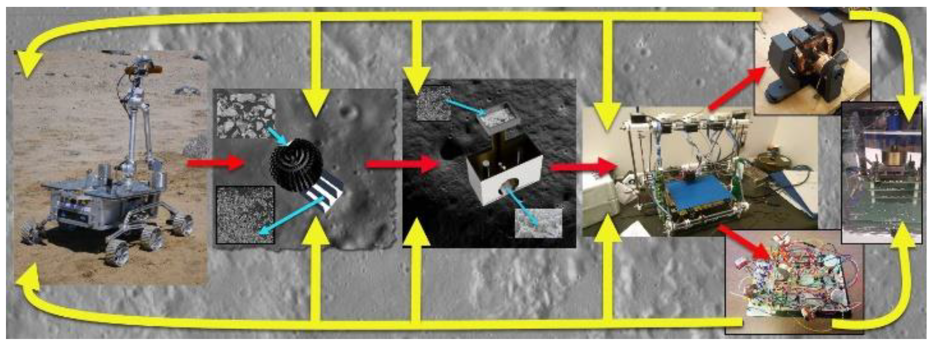
Figure 2.
RepRap 3D printer capable of printing its white plastic structural components.
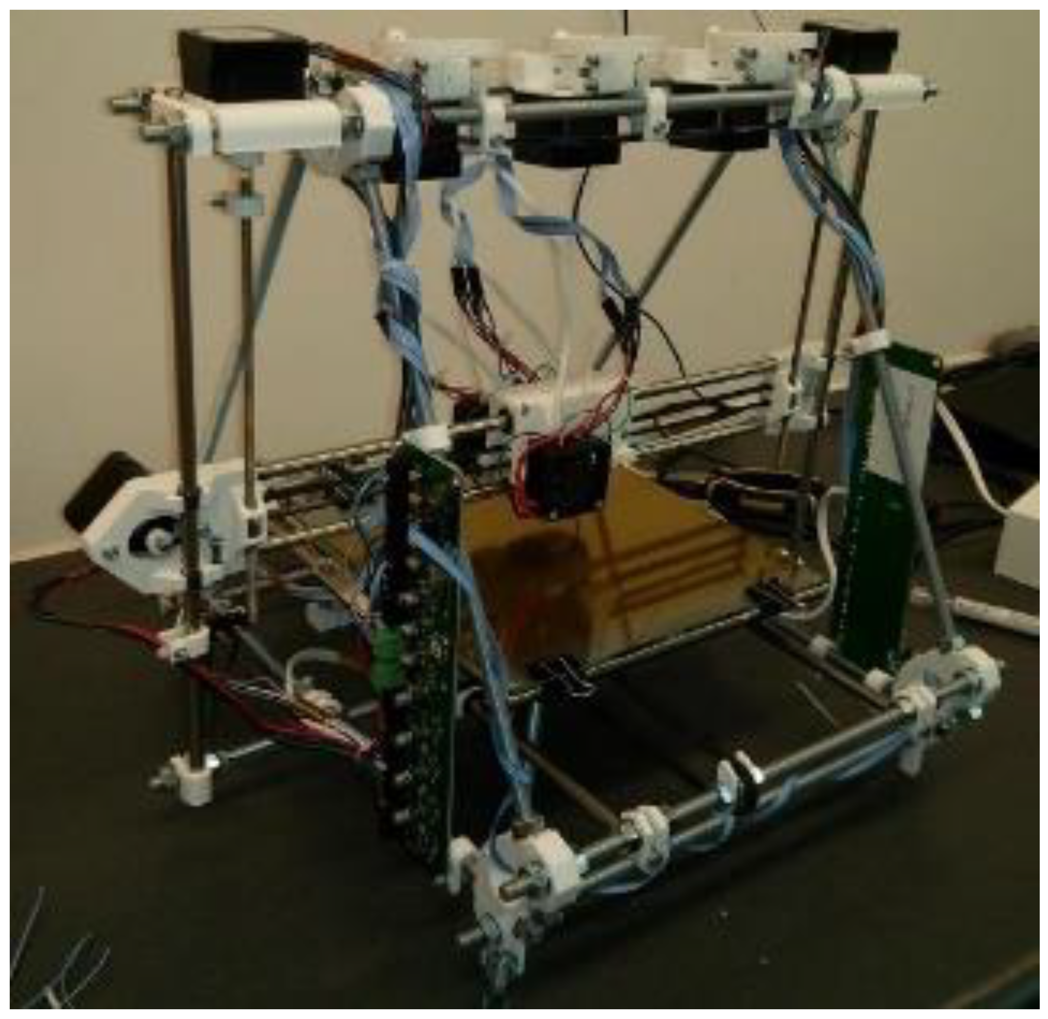
Figure 3.
(a) Nitinol wire-driven rotor based on driving cams; (b) Nitinol wire length required for sufficient stroke to drive the cams.
Figure 3.
(a) Nitinol wire-driven rotor based on driving cams; (b) Nitinol wire length required for sufficient stroke to drive the cams.
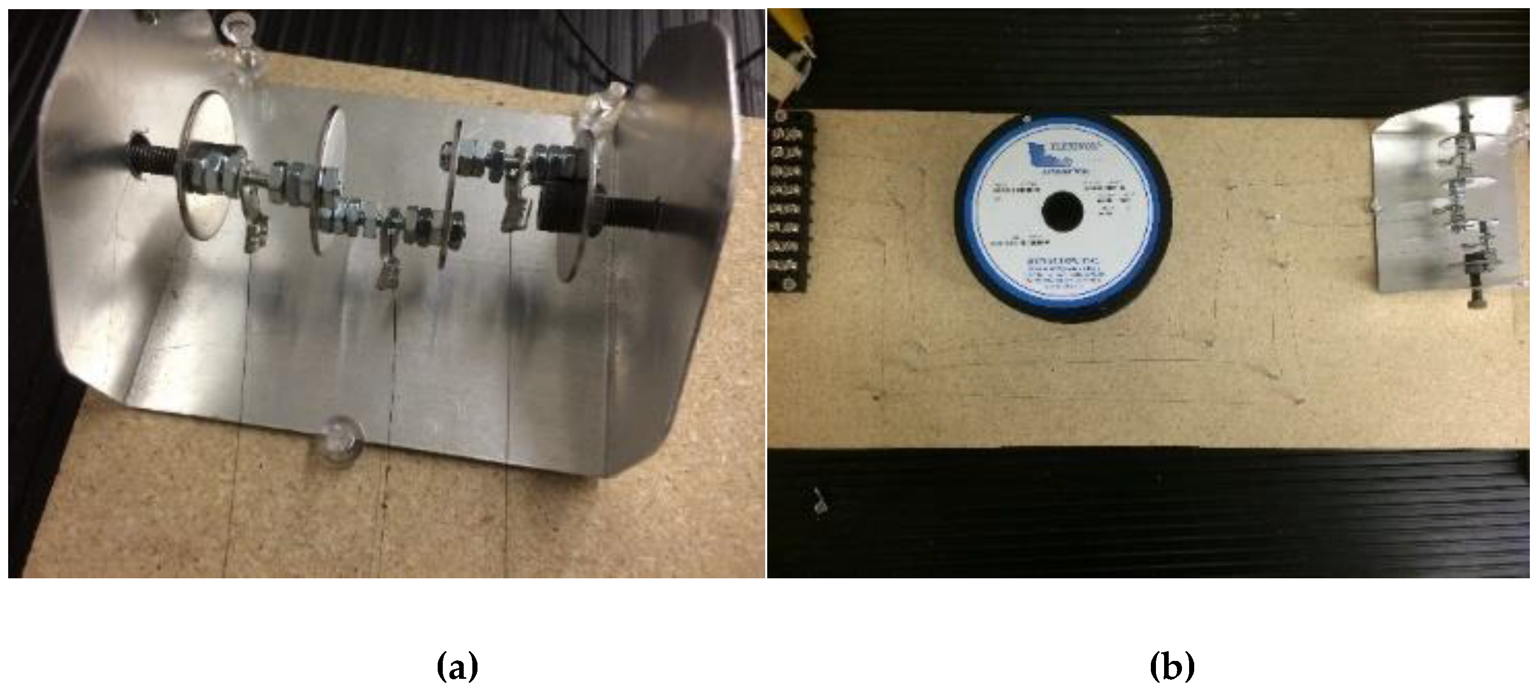
Figure 4.
Armature windings of each layer are angled to the radial direction allowing more conductors to be accommodated: (a) single layer; (b) multiple layers (from [40]); (c) spiral conductor pattern (from [41]).
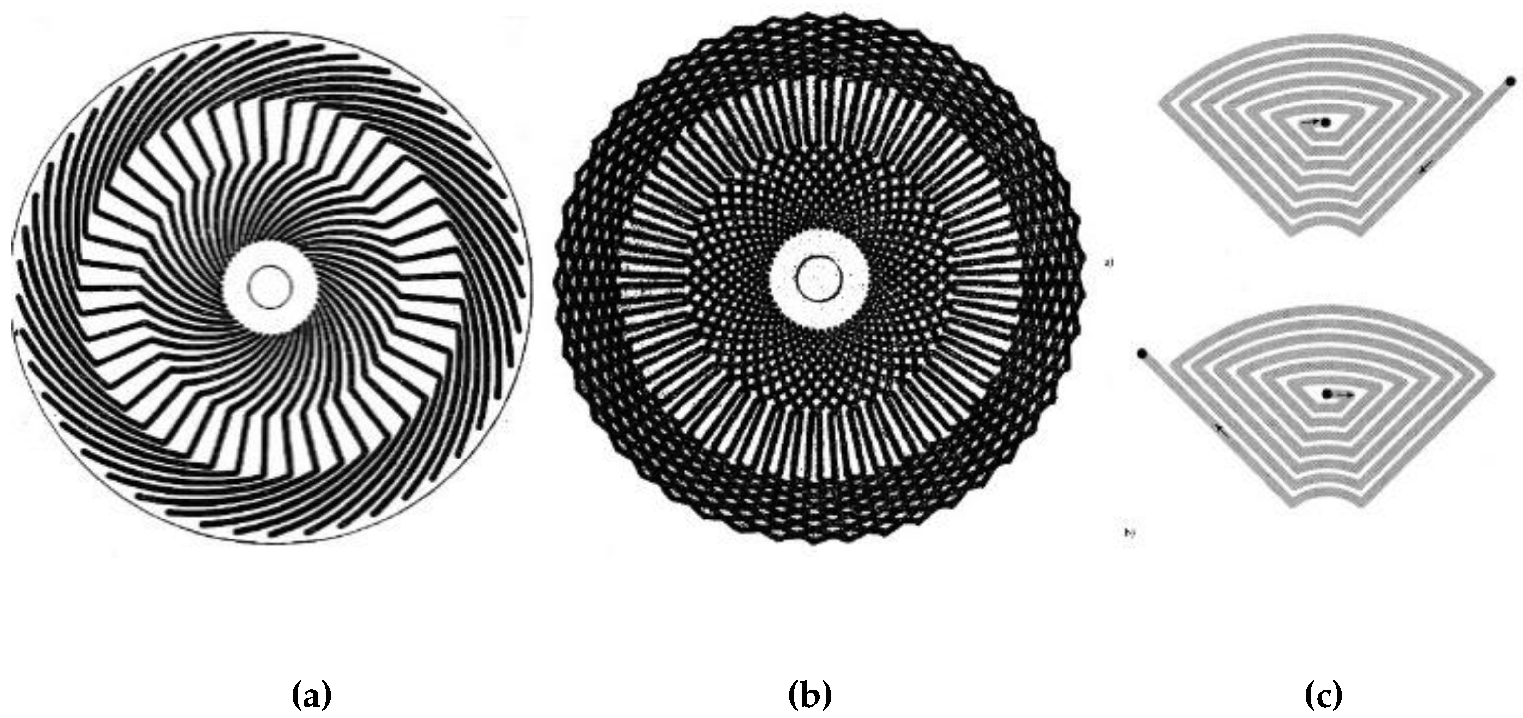
Figure 5.
Dynamometer test apparatus.
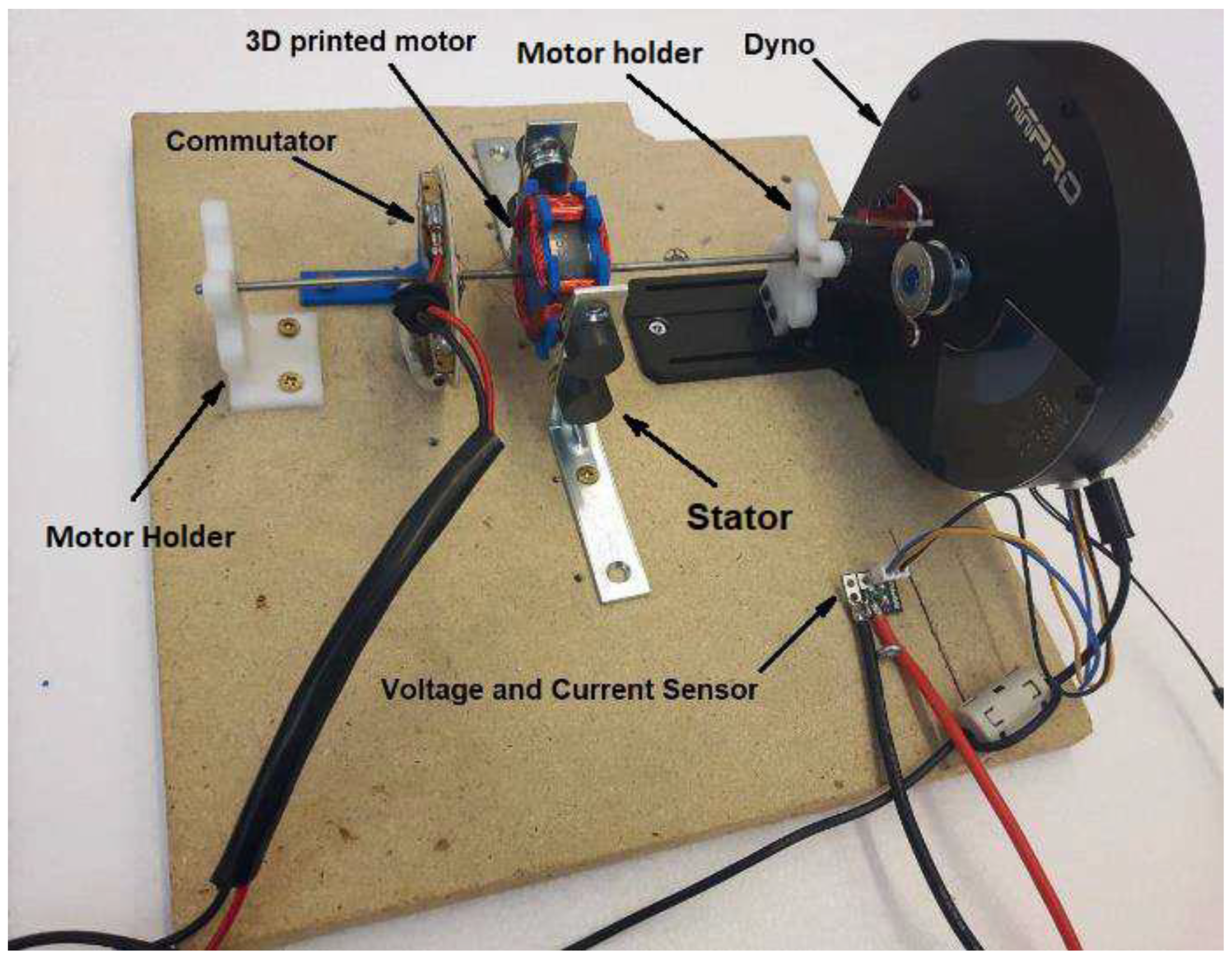
Figure 6.
(a) Power supply and multimeter test apparatus; (b) Power supply, multimeter and oscilloscope.
Figure 6.
(a) Power supply and multimeter test apparatus; (b) Power supply, multimeter and oscilloscope.
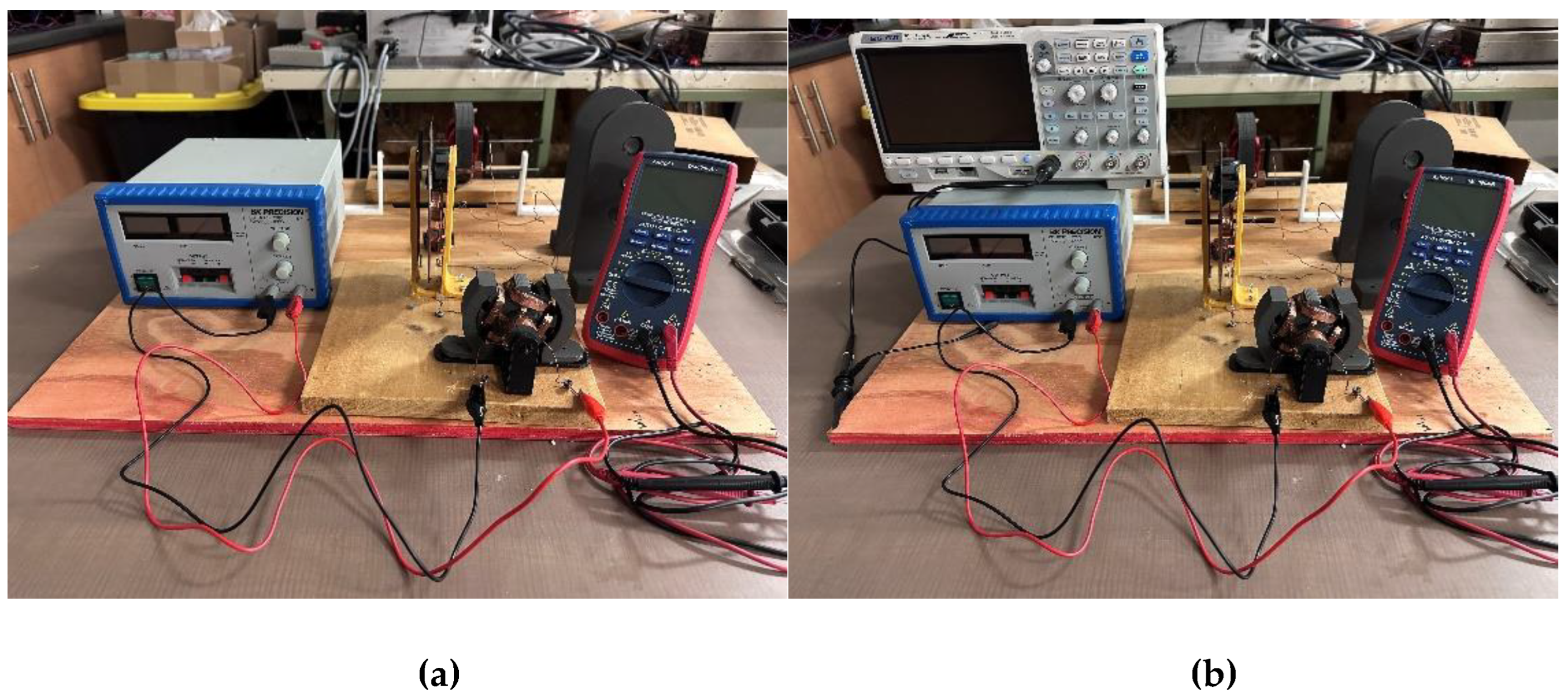
Figure 7.
Automatic wire winder.
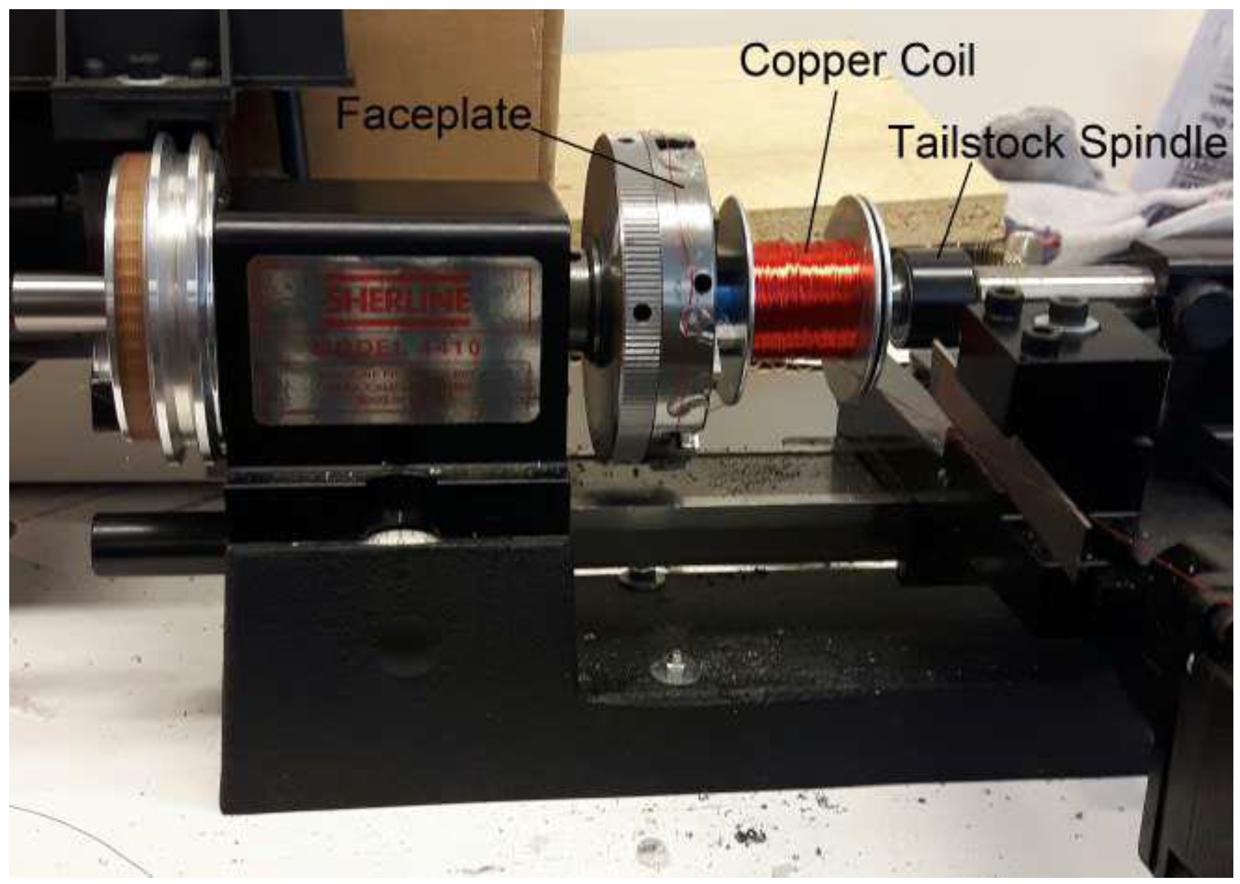
Figure 8.
3D printed rotors with PLA endcaps and commutators: (a) ProtoPastaTM magnetic PLA, (b) PLA with Fe-3%Si, (c) PLA with Fe-6.5%Si.
Figure 8.
3D printed rotors with PLA endcaps and commutators: (a) ProtoPastaTM magnetic PLA, (b) PLA with Fe-3%Si, (c) PLA with Fe-6.5%Si.
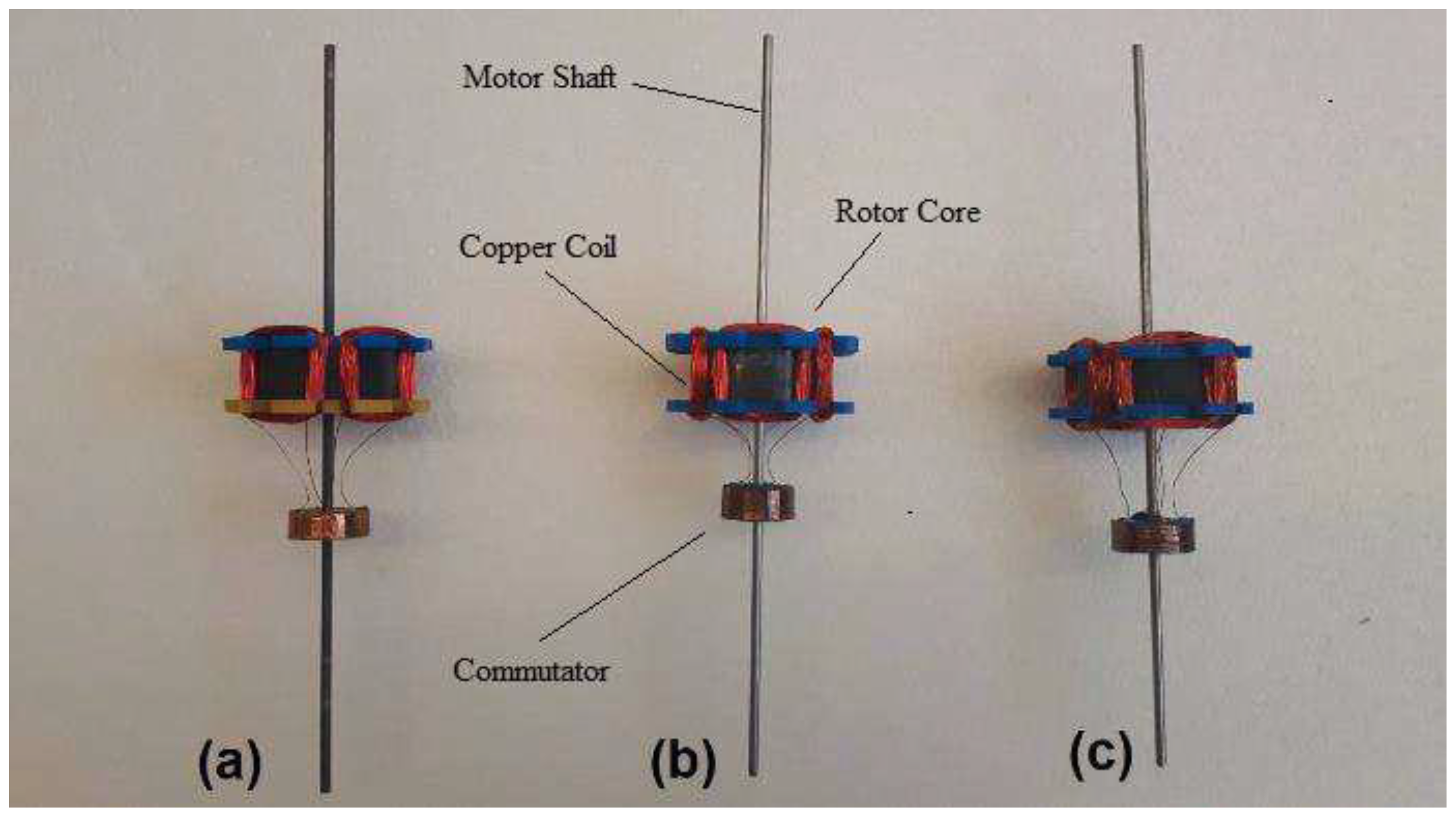
Figure 9.
3D printed Proto-PastaTM rotor.
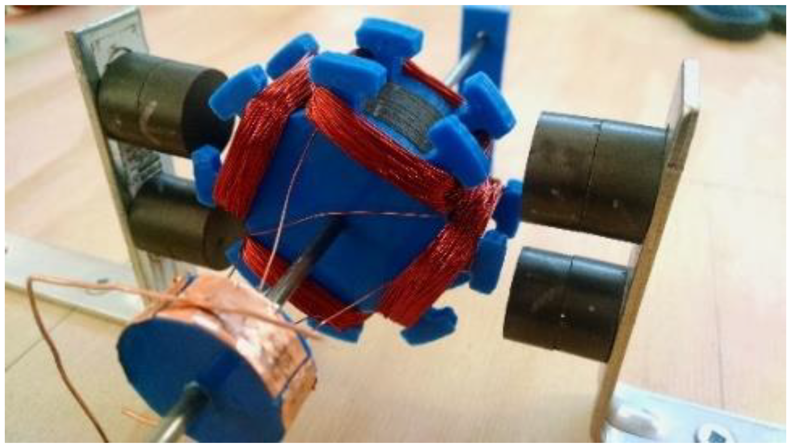
Figure 10.
(a) rotor RPM characteristics; (b) rotor torque characteristics.
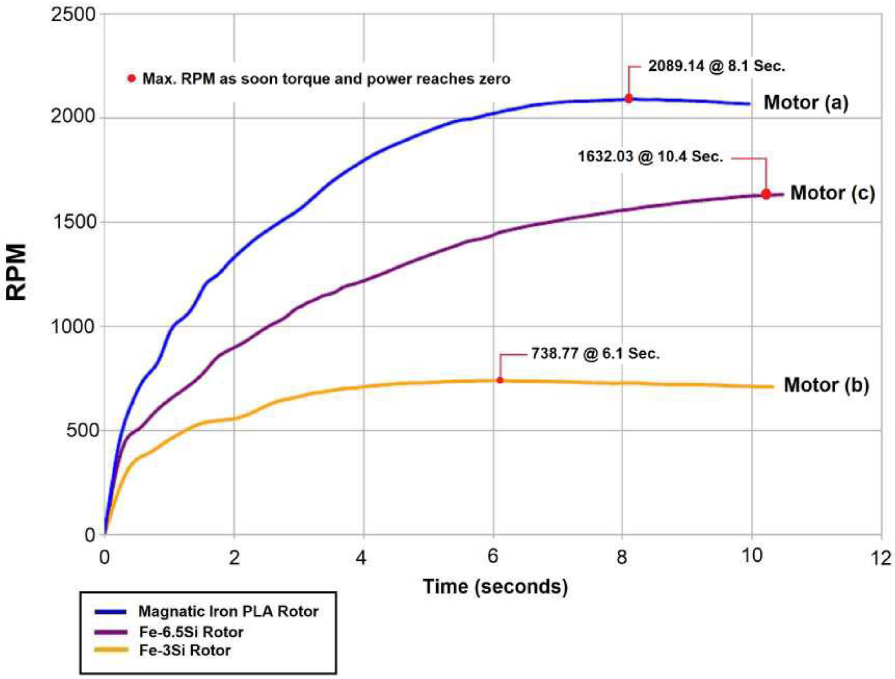
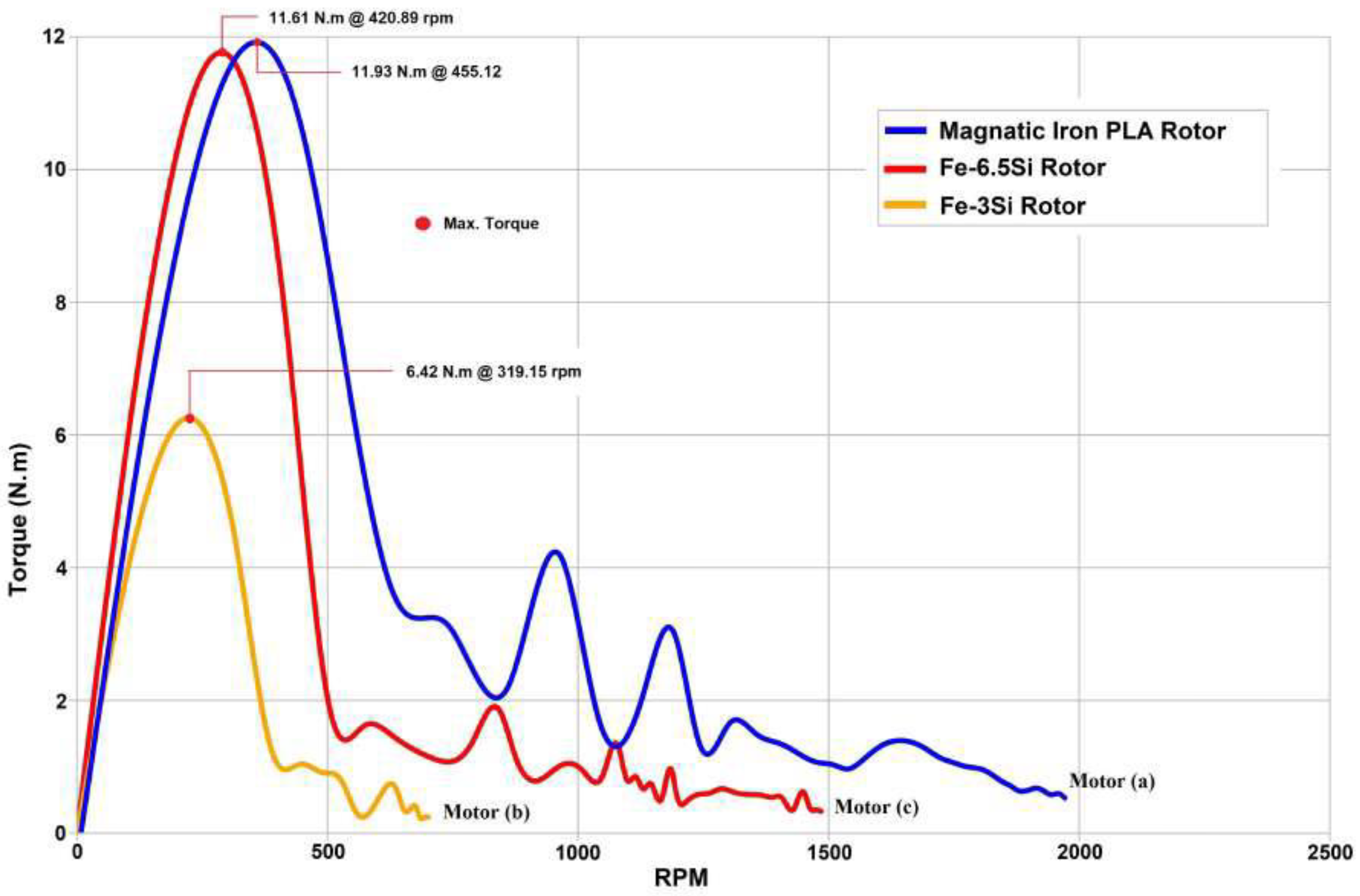
Figure 11.
3D printed variable reluctance motor.
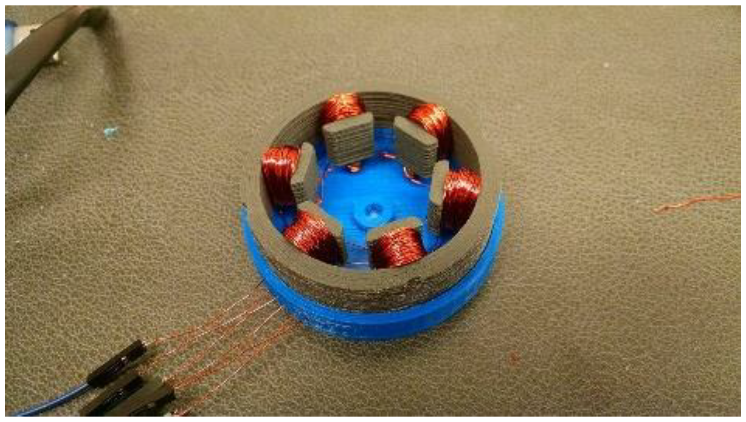
Figure 12.
(a) 3D printed dual excitation motor using only soft magnetic material; (b) its dimensions; (c) 3D printed motor in a self-deployment configuration.
Figure 12.
(a) 3D printed dual excitation motor using only soft magnetic material; (b) its dimensions; (c) 3D printed motor in a self-deployment configuration.
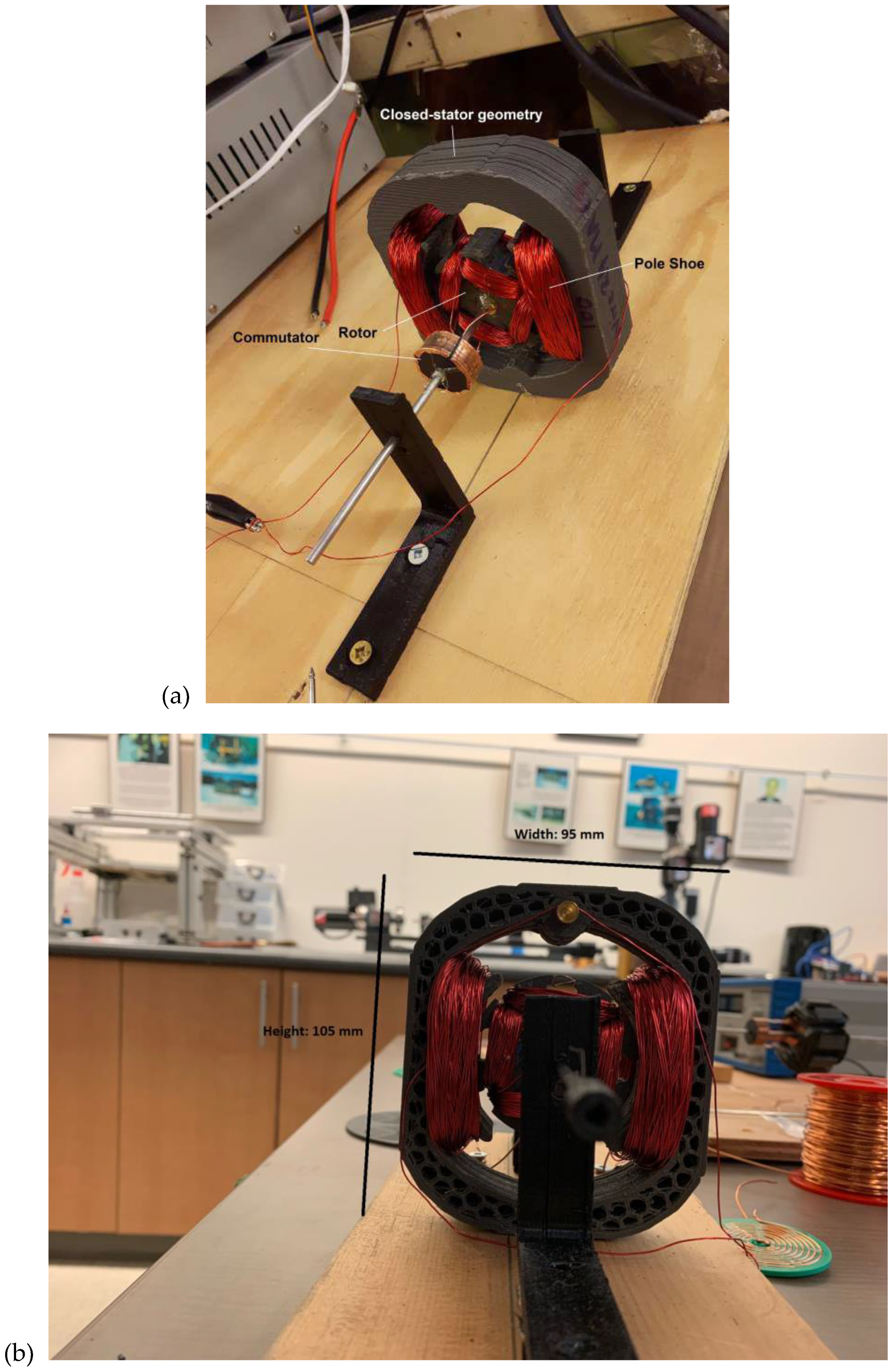
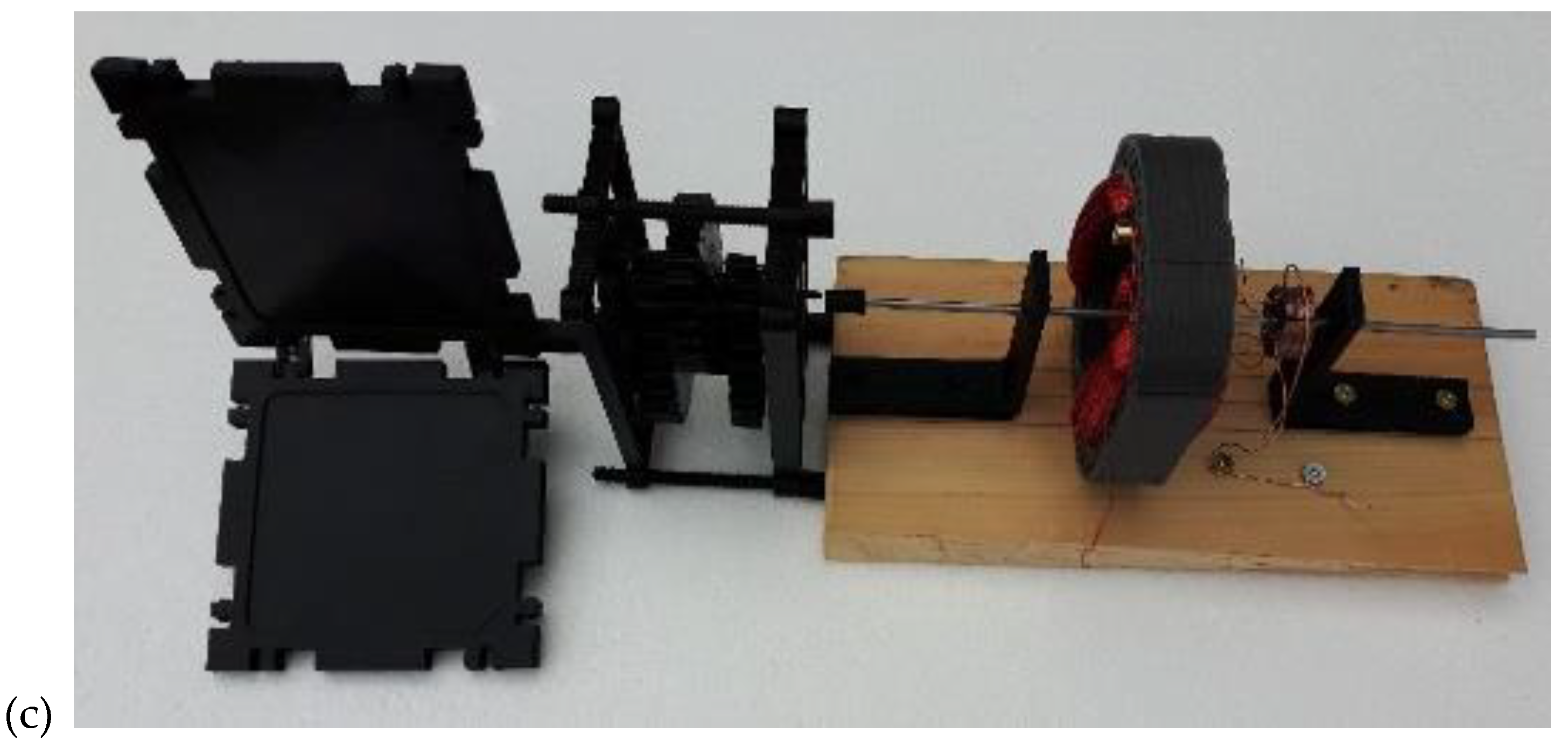
Figure 13.
(a) Oak Ridge 3D printed rare earth bonded permanent magnets; (b) 3D printed magnets embedded in 3D printed magnetic PLA stator.
Figure 13.
(a) Oak Ridge 3D printed rare earth bonded permanent magnets; (b) 3D printed magnets embedded in 3D printed magnetic PLA stator.
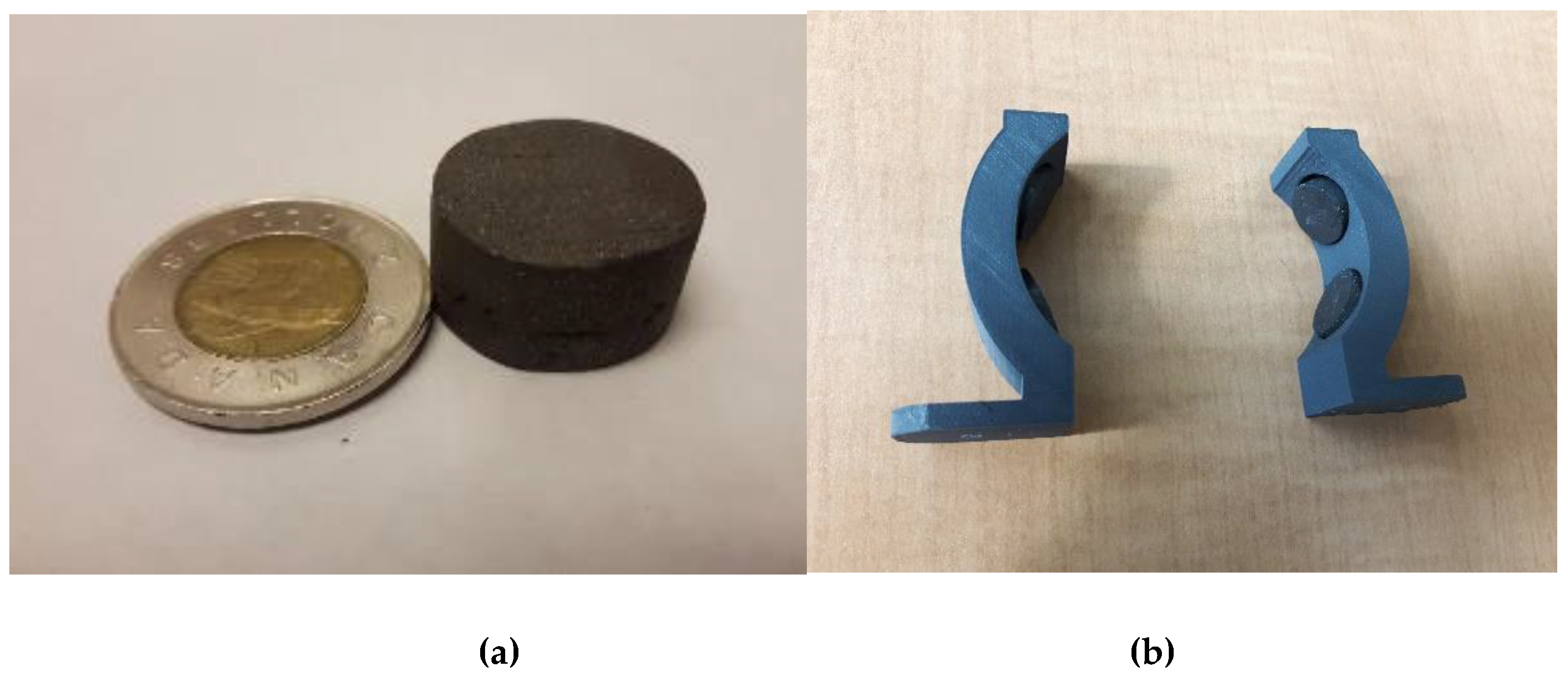
Figure 14.
Pancake motor configuration.
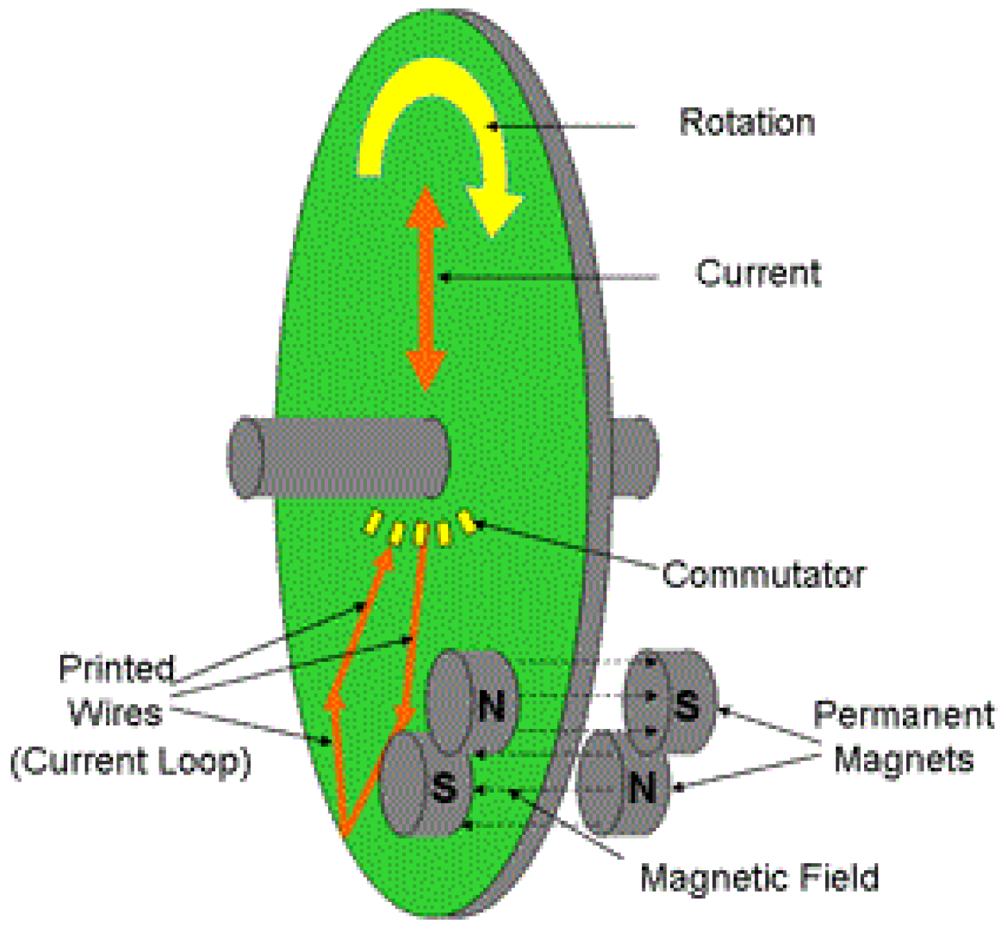
Figure 15.
(a) photolithographically-etched PCB; (b) pancake rotor comprising two double-sided PCBs.
Figure 15.
(a) photolithographically-etched PCB; (b) pancake rotor comprising two double-sided PCBs.
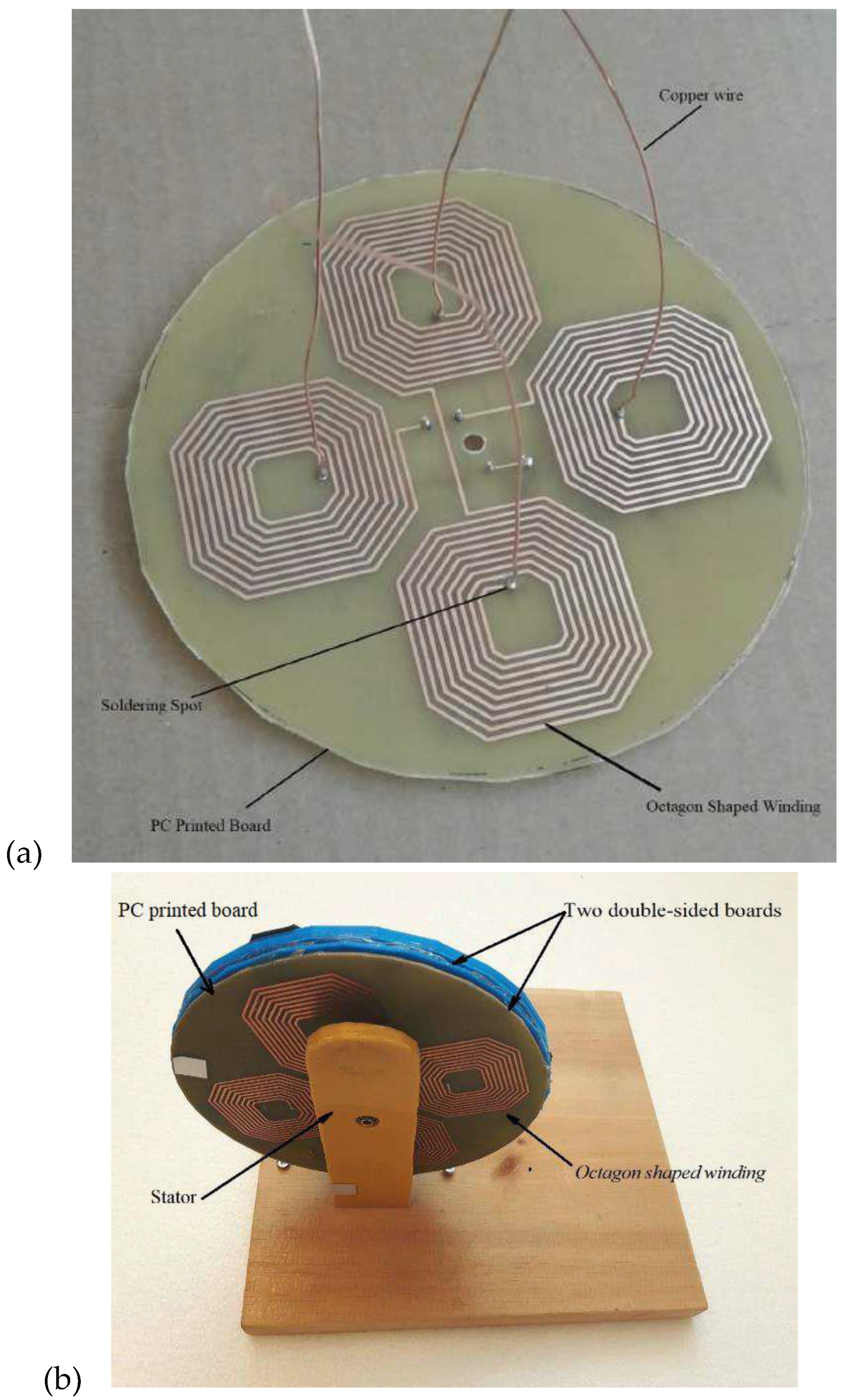
Figure 16.
Copper impregnated PLA coils extruded onto a ProtoPastaTM pancake rotor.
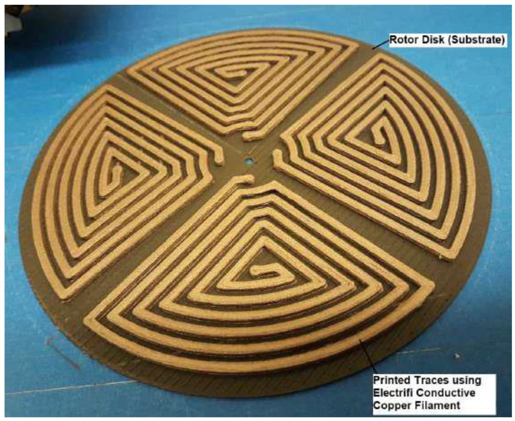
Figure 17.
(a) Cricut Explorer Air 2 cutter; (b) LOM-type copper coils on pancake rotor; c) rotor mounted into a stator with commutator .
Figure 17.
(a) Cricut Explorer Air 2 cutter; (b) LOM-type copper coils on pancake rotor; c) rotor mounted into a stator with commutator .
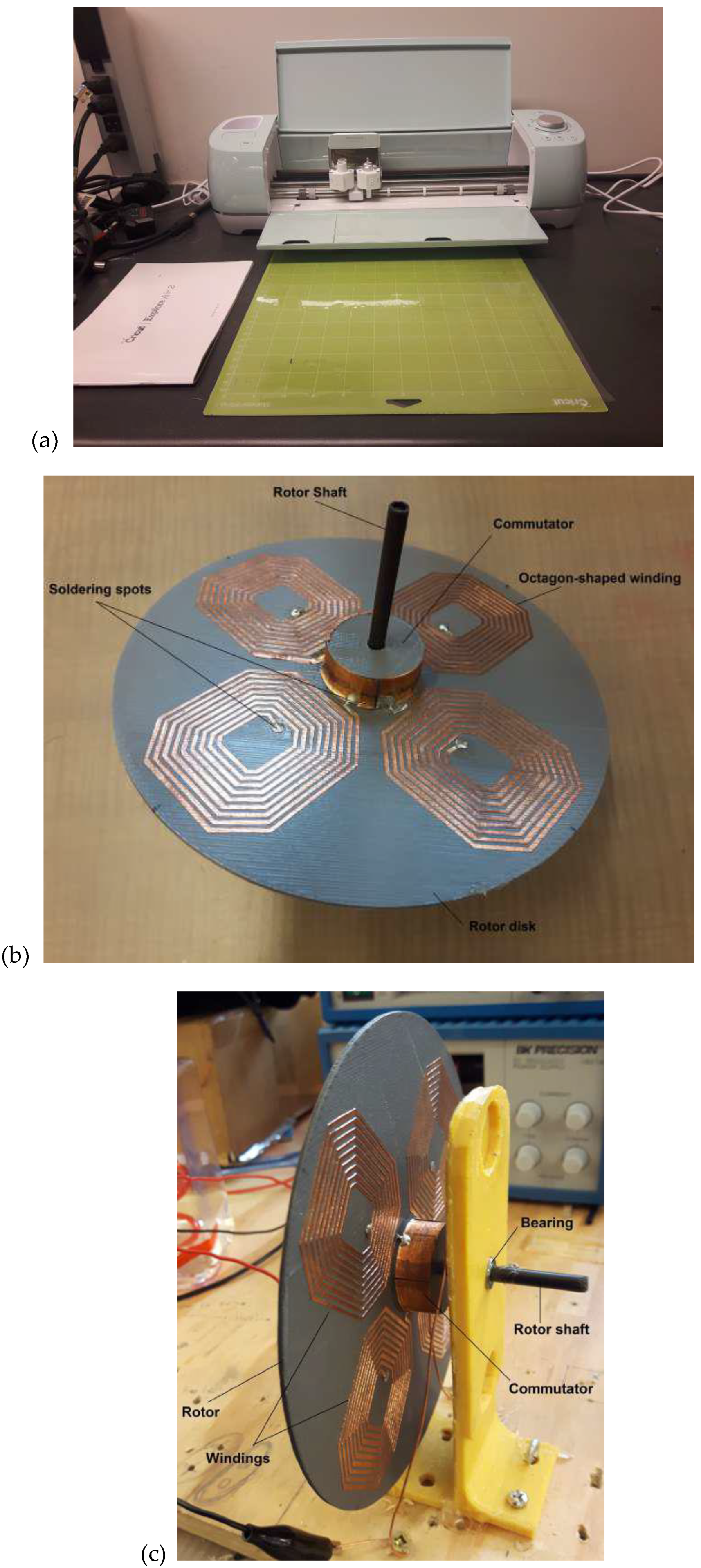
Figure 18.
(a) 3D printed parts of the 3D printed DC motor less coils and commutator; (b) 3D printed rotor with wound copper coils and commutator.
Figure 18.
(a) 3D printed parts of the 3D printed DC motor less coils and commutator; (b) 3D printed rotor with wound copper coils and commutator.
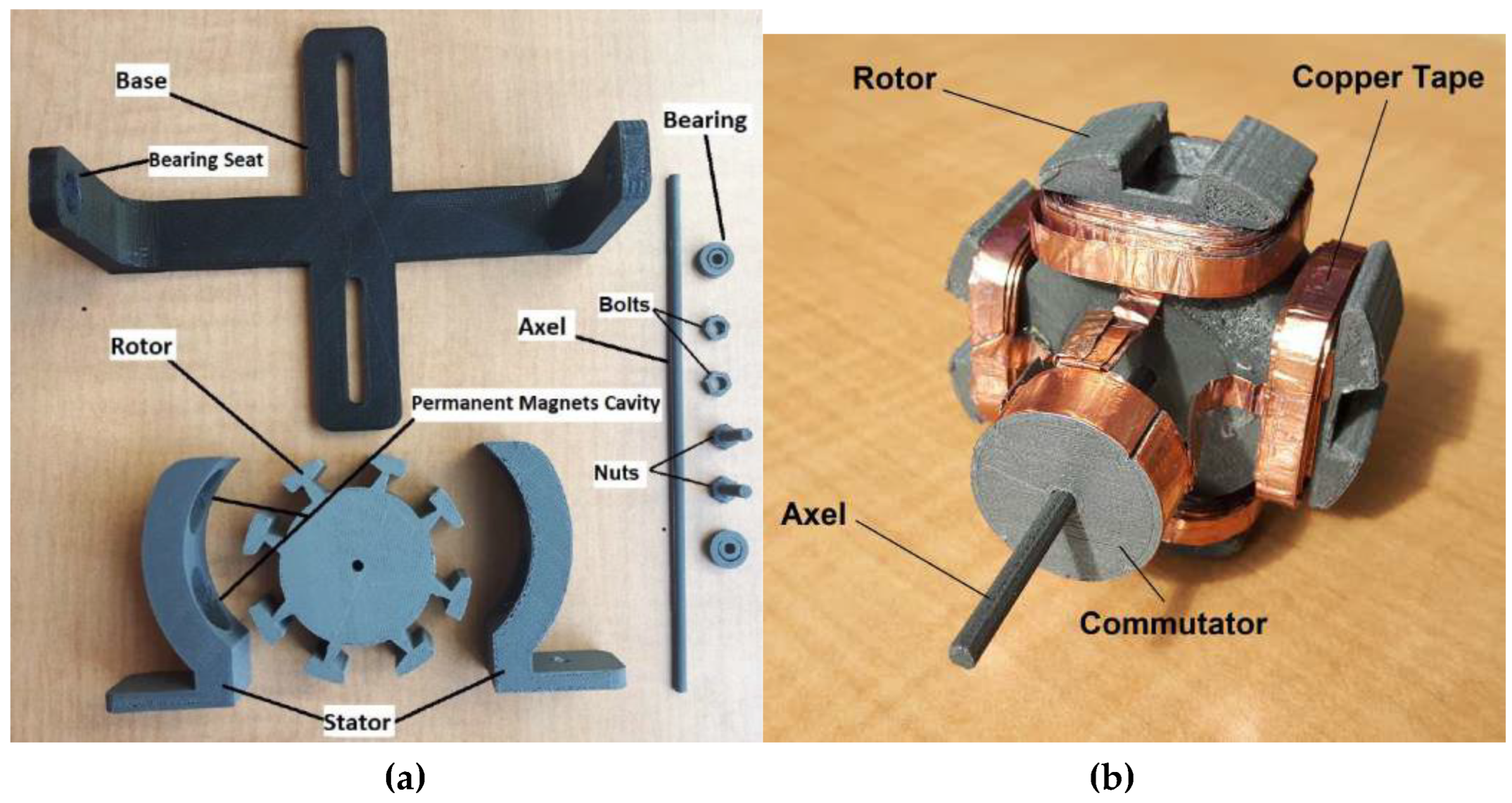
Figure 19.
3D printed DC motor.
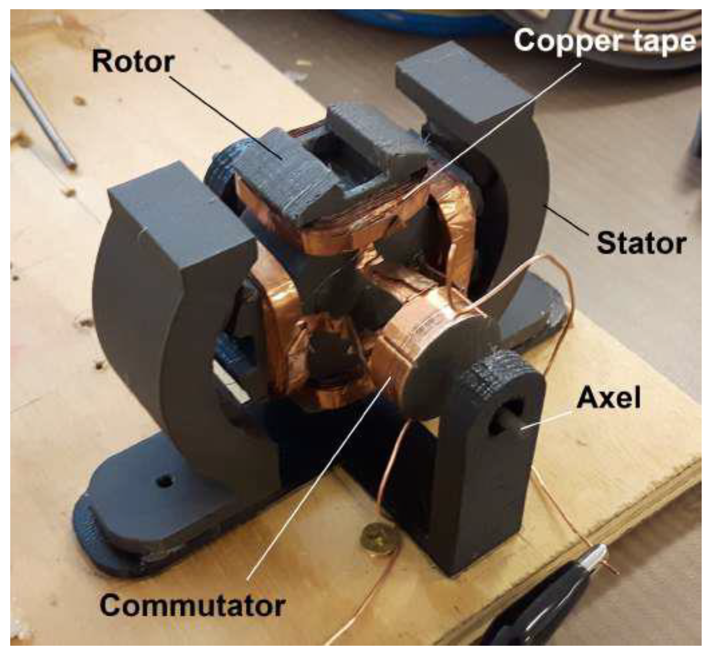
Figure 20.
Performance characteristics of the fully 3D printed DC motor: (a) angular speed-time curve; (b) torque-time curve.
Figure 20.
Performance characteristics of the fully 3D printed DC motor: (a) angular speed-time curve; (b) torque-time curve.
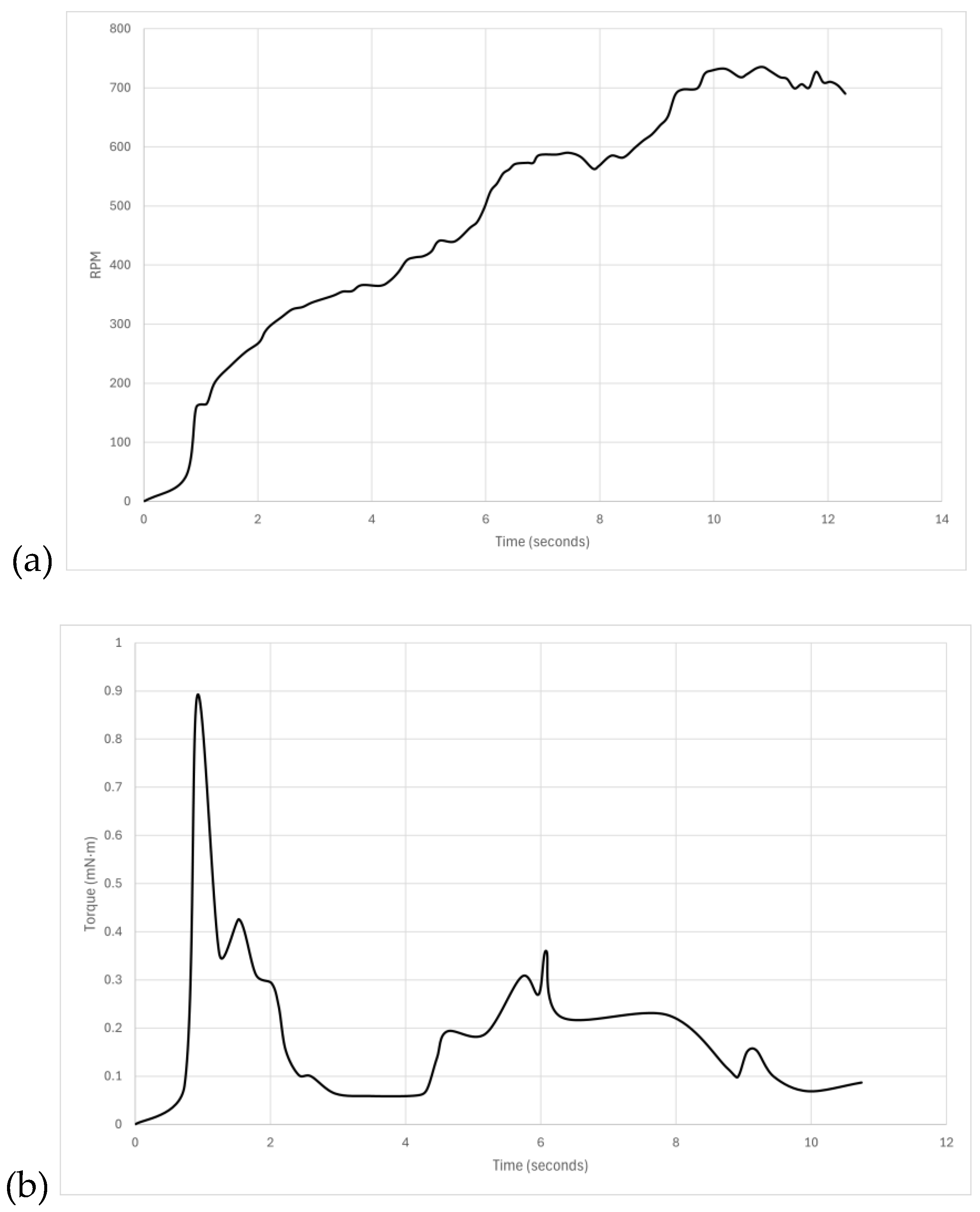
Figure 21.
Disassembled Dybamite DYN 1171 motor.
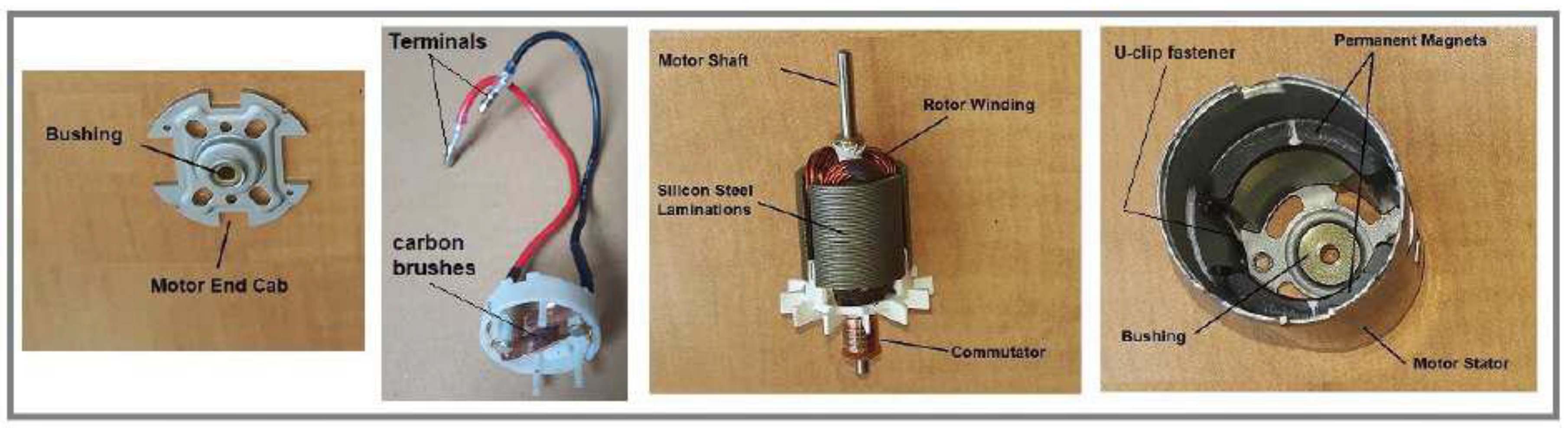
Figure 22.
(a) 3D printed parts of motor; (b) partially assembled and wound with copper wire.
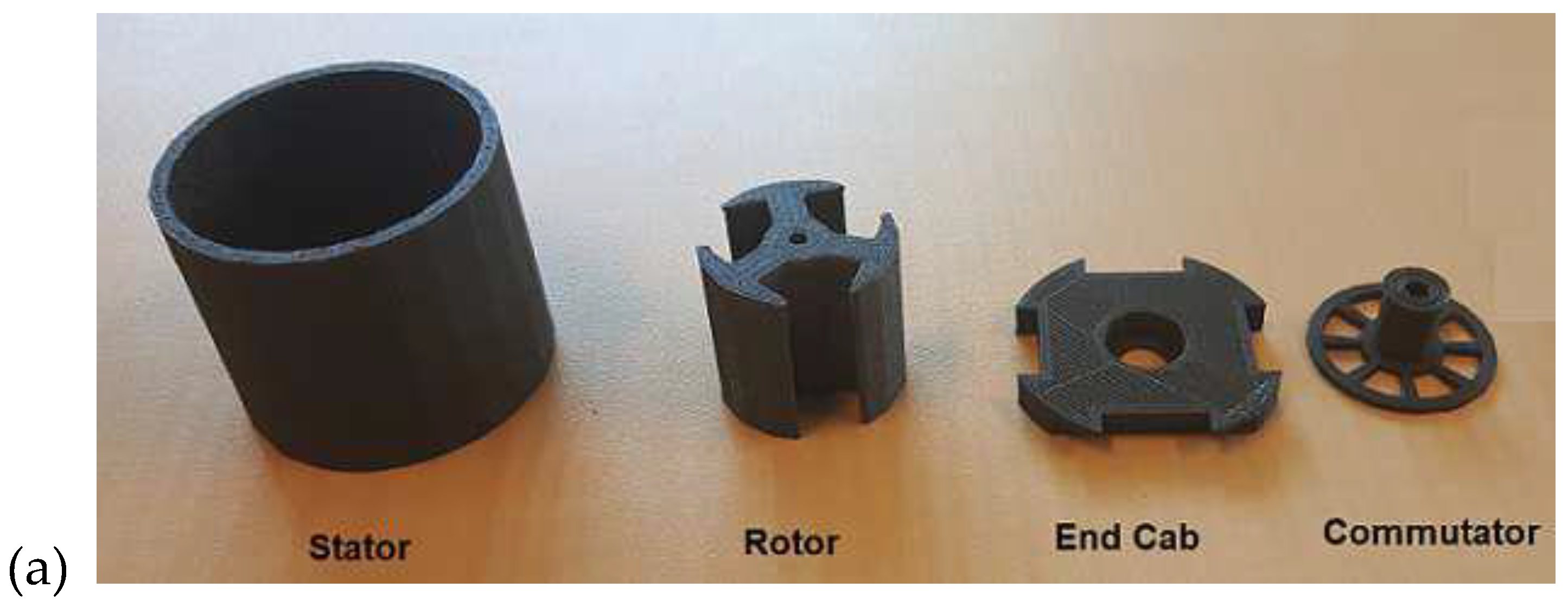
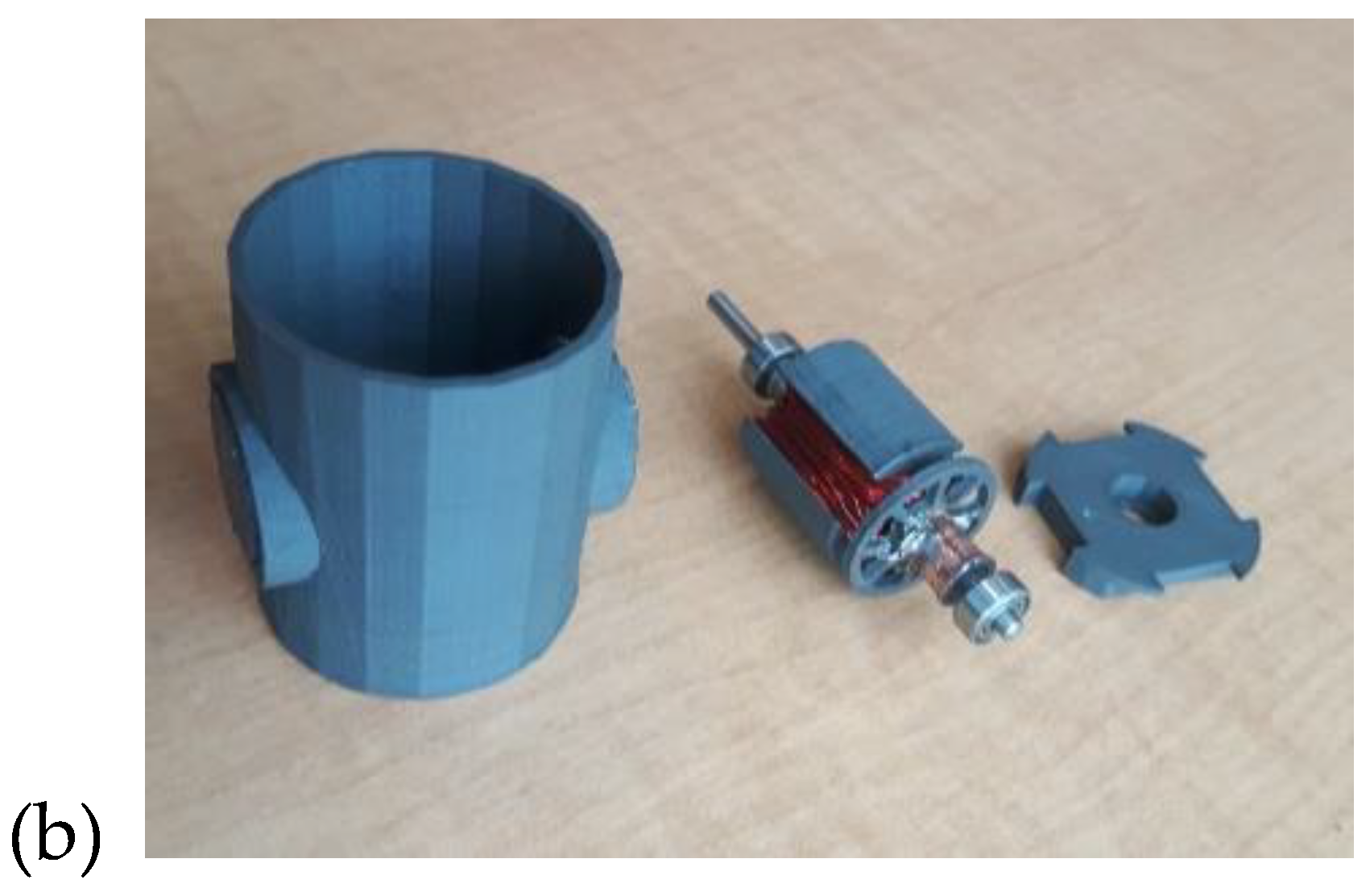
Figure 23.
(a) Off-the-shelf motor; (b) 3D printed version (excluding stator casing).
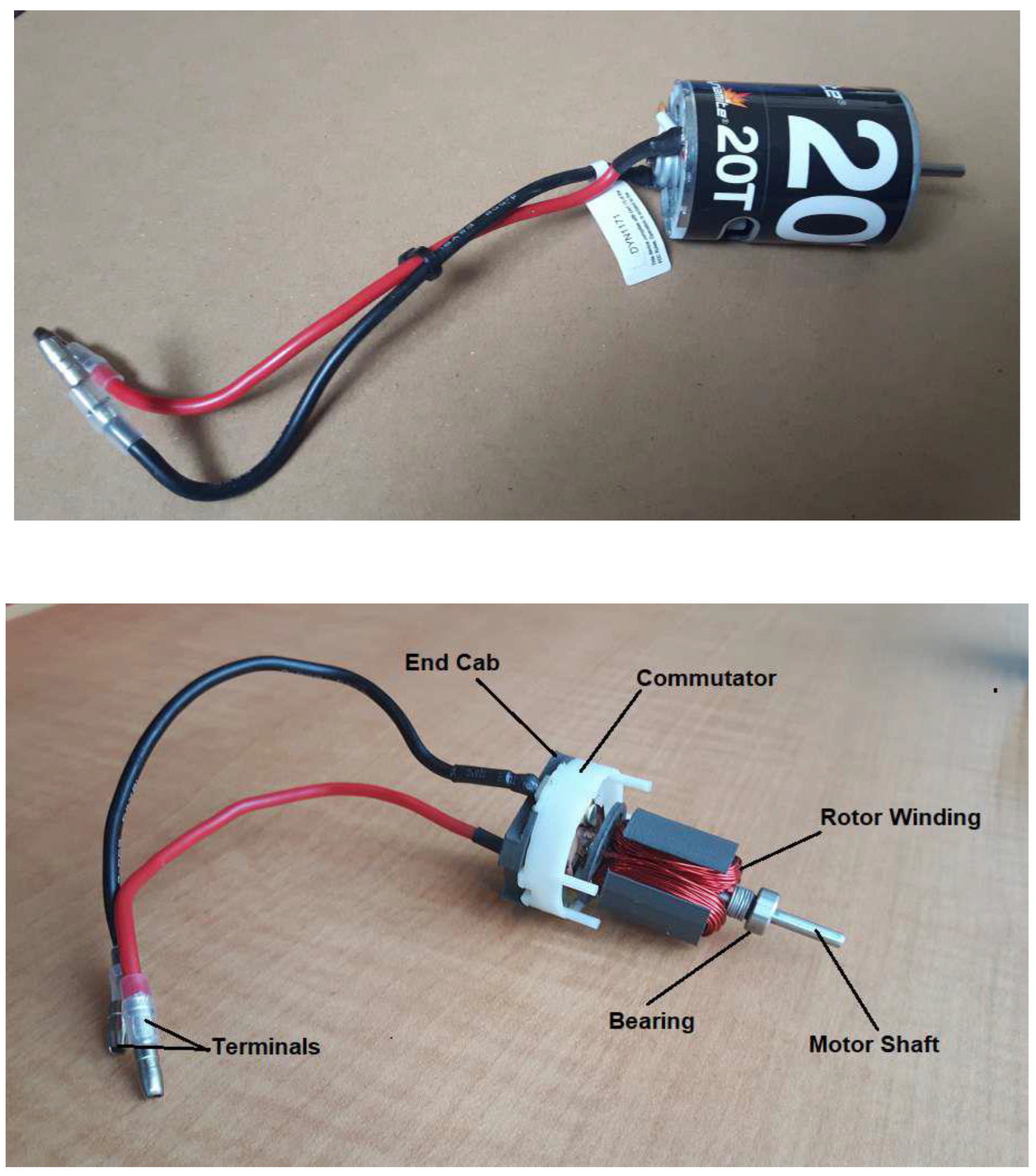
Figure 24.
RPM characteristics of 3D printed versions of a commercial production motor.
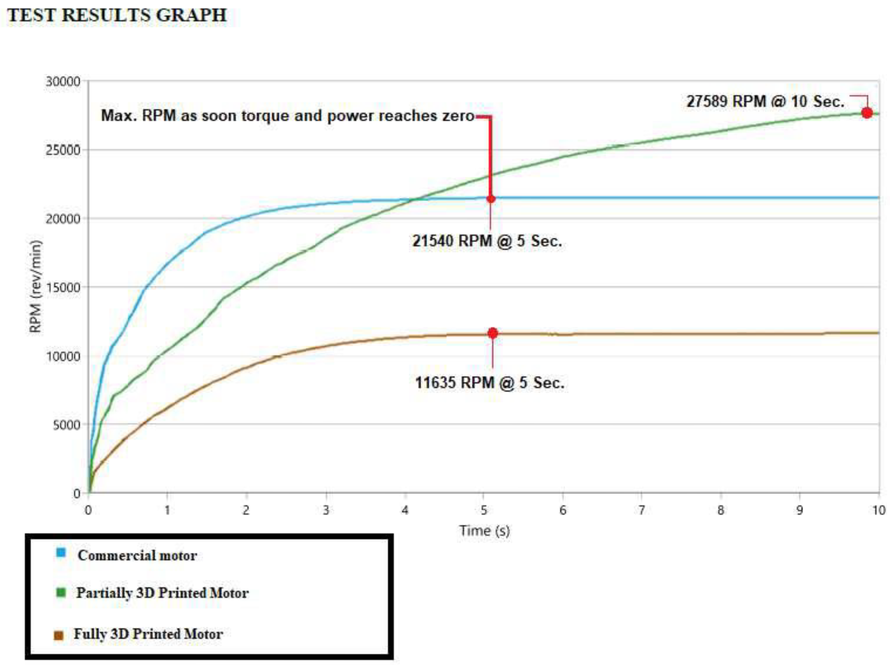
Figure 25.
(a) Molten aluminium track melted onto silicone substrate; (b) In-house custom multi-material 3D printer prototype under development .
Figure 25.
(a) Molten aluminium track melted onto silicone substrate; (b) In-house custom multi-material 3D printer prototype under development .
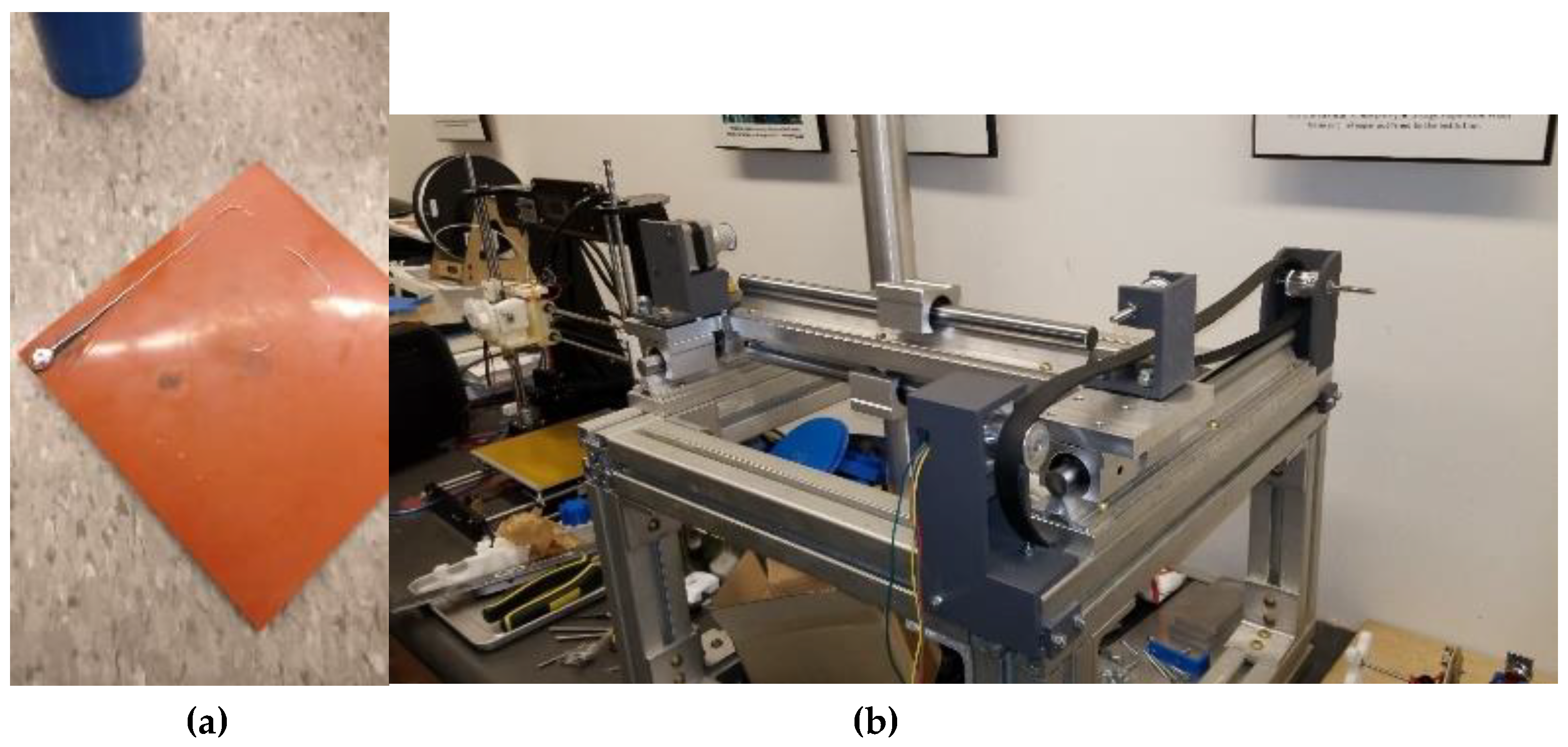

Table 1.
Maximum magnetic energy density in airgap (BHmax) and coercive force of permanent magnets.
| Permanent magnetic material | BHmax | Coercive force (kA/m) |
|---|---|---|
| NdFeB | 10-40 | 750-2000 |
| Ferrite | 3.5 | 100-300 |
| Alnico 1 or 2 | 5.5 | 37-45 |
Disclaimer/Publisher’s Note: The statements, opinions and data contained in all publications are solely those of the individual author(s) and contributor(s) and not of MDPI and/or the editor(s). MDPI and/or the editor(s) disclaim responsibility for any injury to people or property resulting from any ideas, methods, instructions or products referred to in the content. |
© 2025 by the authors. Licensee MDPI, Basel, Switzerland. This article is an open access article distributed under the terms and conditions of the Creative Commons Attribution (CC BY) license (http://creativecommons.org/licenses/by/4.0/).
Copyright: This open access article is published under a Creative Commons CC BY 4.0 license, which permit the free download, distribution, and reuse, provided that the author and preprint are cited in any reuse.


