Preprint
Article

This version is not peer-reviewed.

A Controlled System for Parahydrogen Hyperpolarization Experiments

A peer-reviewed article of this preprint also exists.

Submitted:

11 October 2025

Posted:

13 October 2025

You are already at the latest version

Abstract

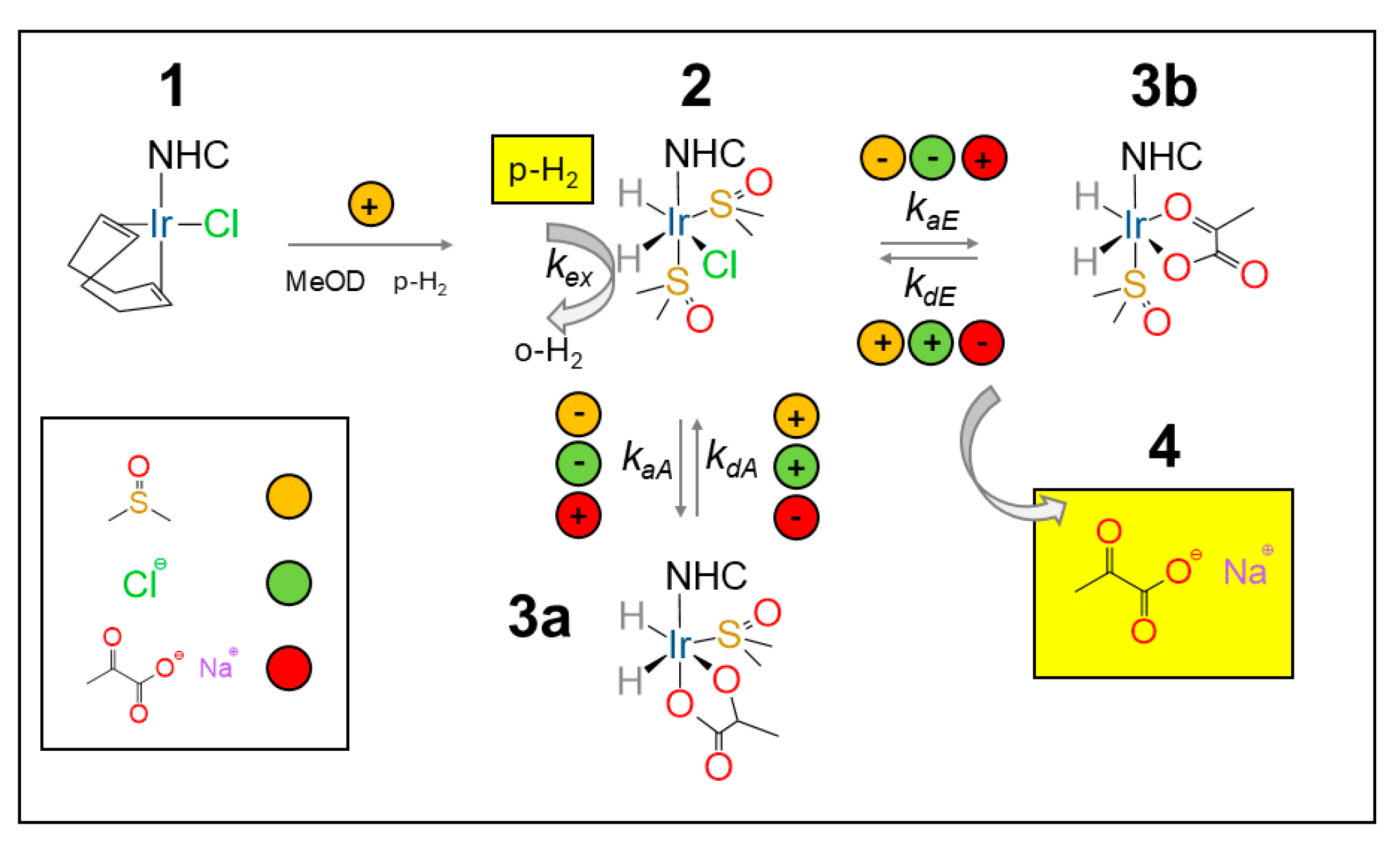
Parahydrogen-induced hyperpolarization (PHIP) was introduced nearly four decades ago as an elegant solution to one of the fundamental limitations of nuclear magnetic resonance (NMR) — its notoriously low sensitivity. By converting the spin order of parahydrogen into nuclear spin polarization, NMR signals can be boosted by several orders of magnitude. Here we present a portable, compact and cost-effective setup that brings PHIP and Signal Amplification By Reversible Exchange (SABRE) experiments within easy reach, operating seamlessly across ultra-low-field (0–10 μT) and high-field (>1 T) conditions at 50% parahydrogen enrichment. The system provides precise control over bubbling pressure, temperature, and gas flow, enabling systematic studies of how these parameters shape hyperpolarization performance. Using the benchmark Ir-IMes catalyst, we explore the catalyst activation time and response to parahydrogen flow and pressure. Polarization transfer experiments from hydrides to [1-13C]pyruvate leading to the estimation of heteronuclear J-coupling are also presented. We further demonstrate the use of Chloro(1,5-cyclooctadiene)[1,3-bis(2,6-diisopropylphenyl)imidazolidin-2-ylidene]iridium(I) (Ir-SIPr), a recently introduced catalyst that can also be used for pyruvate hyperpolarization. The proposed design is robust, reproducible, and easy to implement in any laboratory, widening the route to explore and expand the capabilities of parahydrogen-based hyperpolarization.

Keywords: 
;  ;  ;  

1. Introduction

Nuclear magnetic resonance (NMR) and magnetic resonance imaging (MRI) are valuable techniques used throughout chemistry, physics, and medicine [1,2,3]. Yet, their impact is inherently limited by low sensitivity and poor signal-to-noise ratio (SNR). The nuclear spin polarization, representing the fractional imbalance between energy levels responsible for the NMR signal, follows a simple expression, proportional to ℏγB0/2kT, where ℏ is the reduced Planck constant, γ the gyromagnetic ratio, B0 the magnetic field, k the Boltzmann constant, and T the temperature [4]. Conventional strategies to overcome this limitation rely on higher fields and/or lower temperatures. Brute-force nuclear hyperpolarization follows this route [5,6,7,8]. Reaching very high fields, however, is technically demanding. Commercial NMR magnets based on superconducting alloys such as NbTi or Nb₃Sn require cooling with liquid helium. The largest commercially available systems operate at ~28 T, weigh several tons, and cost millions of euros, yet still cannot break the fundamental scaling granting only up to about 1 proton spin over 104 to contribute to the NMR signal. On the other side, cryoprobes and microcoils reduce noise on the detection side [9,10]
Hyperpolarization provides an alternative [11,12,13]. Several distinct methods have been developed, depending on the source of polarization (i.e., the signal) to be transferred to the nuclear spins: from electron spins, as in Dynamic Nuclear Polarization (DNP) [12,14,15,16,17,18,19,20]; from parahydrogen, as in Parahydrogen-Induced Polarization (PHIP) and Signal Amplification by Reversible Exchange (SABRE) [21,22,23,24,25,26]; from noble gases, as in Xe- and He-polarization [27]; or from quantum tunneling effects, as in Quantum Rotor-Induced Polarization [28,29]. DNP remains the most widely adopted method, capable of yielding signal enhancements of several hundredfold—either in solids under magic-angle spinning at cryogenic temperatures or in liquids via stochastic electron–nuclear interactions (Overhauser effect) [17,30,31,32,33,34]. Dissolution DNP (dDNP) extends this signal amplification to several thousand fold to solution-state NMR by polarizing frozen samples at ~1.2 K and rapidly dissolving them, enabling enhanced detection of metabolic probes such as pyruvate [3,15,18,35,36]. Despite its impact, DNP remains complex, expensive, and difficult to maintain.
Parahydrogen-based methods offer a simpler path [21,22]. PHIP and its variant PHIP Side Arm Hydrogenation (PHIP-SAH) [37,38] can match the performance of dDNP for many targets, while SABRE [25,26] allows repeated experiments on the same sample at a fraction of the cost. These techniques can hyperpolarize nuclei in seconds to minutes, without cryogenics or high-power microwaves. Their efficiency, however, depends critically on controlling key variables: magnetic field, parahydrogen enrichment, bubbling time, pressure, and flow rate.
In this work, we present an easily implementable parahydrogen and bubbling apparatus that provides control over pressure, flow rate, and temperature during parahydrogen-based hyperpolarization experiments.
Several systems for parahydrogen at different enrichment levels have been reported in the literature. Some operate at pressures around 490 psi (≈33 bar) and reach enrichments above 48%, up to nearly 100%, with designs aimed at clinical applications [39,40,41,42,43,44,45]. Commercial solutions are also available from Bruker (e.g., the BPHG90, delivering ≈87% parahydrogen at a cost above €100 000), Hyperspin Scientific (http://www.hyperspin.biz/), and Xeus Technologies (https://www.xeus-technologies.com/), which additionally offers a complete parahydrogen distribution system.
Our goal here is not to introduce an alternative method, but rather to demonstrate that a wide range of experiments—with full control over key experimental parameters—can be performed in almost any research environment, including for educational purposes, using relatively modest resources.
In many laboratories, parahydrogen experiments are still performed by manually shaking a J-Young NMR tube in the fringe field of a magnet, followed by detection at high magnetic field. While this approach can be effective, it raises questions about how well-controlled such experiments can truly be. Conversely, the full automation of parahydrogen bubbling may appear as a technical barrier — one that this work aims to overcome. We describe in detail the construction of a custom switch box that can be operated manually for parahydrogen experiments, while also enabling fully automated high-field operation through the TTL trigger signals available from most NMR spectrometer consoles. Practical examples of implementation are also provided, including pulse sequences used on Bruker instruments.
The proposed system is then employed to evaluate the performance of a recently developed SABRE catalyst for sodium [1-13C]pyruvate experiments, Chloro(1,5-cyclooctadiene)[1,3-bis(2,6-diisopropylphenyl)imidazolidin-2-ylidene]iridium(I) (Ir-SIPr), using a 1.4 T benchtop NMR spectrometer (Oxford XPulse), demonstrating ¹³C hyperpolarization under controlled bubbling conditions, although the sample transfer to the detection field was still performed manually. The same setup is used to perform fully automated high-field experiments (9.4 T) with the well-known Ir-IMes, Chloro(1,5-cyclooctadiene)[1,3-bis(mesityl)imidazolin-2-ylidene]iridium(I), to accurately monitor the catalyst activation time by following the hydride ¹H signals, to conduct polarization transfer experiments from parahydrogen protons to the ¹³C nucleus of [1-¹³C]pyruvate, and to study the dependence of the ¹³C signal intensity on hydrogen flow at 6 bar pressure. Overall, the system presented here—operating even with a 50% parahydrogen fraction—enables a broad range of experiments both at low magnetic fields typical of benchtop systems and at high magnetic fields, thereby significantly widening the applicability of parahydrogen-based hyperpolarization methods.

2. Description of the System

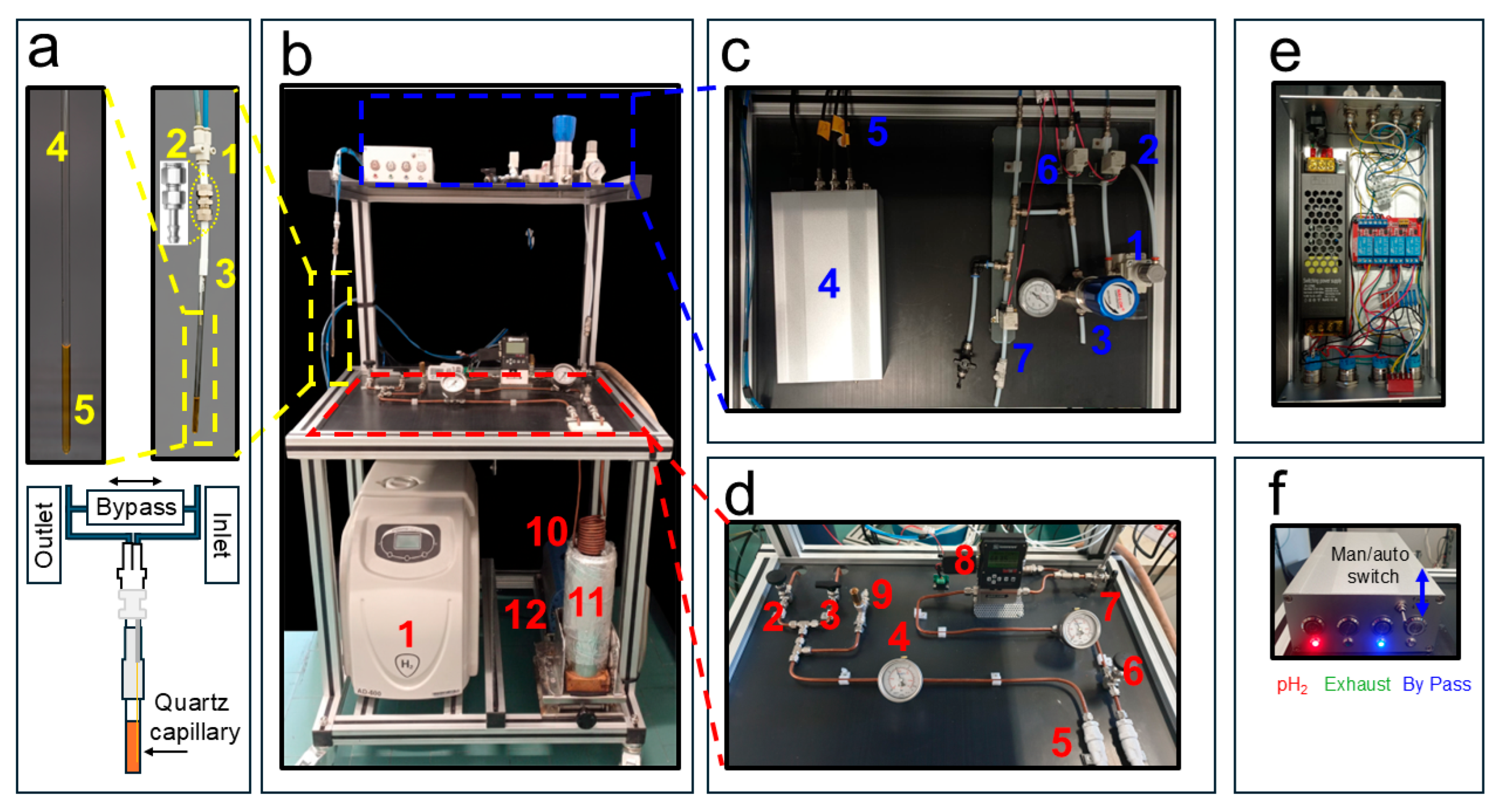
2.1. Parahydrogen Generator

In many laboratories, the hydrogen source is typically represented by high-pressure gas cylinders (≈200 bar), which are commercially available at relatively low cost. In our case, however, considerations related to logistics, safety regulations, and the desire to design a compact and easily transportable setup—allowing parahydrogen experiments to be performed on different NMR instruments—led us to adopt a different solution. A detailed list of components and estimated costs (< 10 k € excluding the hydrogen generator) is provided in Appendix A.
Hydrogen gas is provided by a commercial hydrogen generator (AD-600 Cinel SRL- Italy) (Figure 1b(1)). This unit produces high-purity (> 99.99999%) H2 gas via a PEM (Proton Exchange Membrane) electrolytic H2 generator using deionized water (low conductivity (<1µS/cm). In our case the H2 gas flow is 600 mL/min and it is produced at a user-controllable pressure up to 10 bars. In our experiments, the hydrogen pressure was set to 7.5 bar. The gas produced by the generator was delivered through a 1/8″ Teflon tube, which was subsequently coupled to a 6 mm o.d. copper line. A S-Lok manual ball valve (S-Lok SBV1-3B-S-6M) regulated the gas flow into the system (Figure 1d(2)), while a first pressure gauge (Figure 1d(4))monitored the internal pressure (Swagelok PGI-63B-BG16-CASX). In parallel with the gas inlet, a second 6 mm o.d. outlet copper line is connected via a second manual valve (S-Lok SBV1-S-6M) (Figure 1d(3)) to a diaphragm pump (Vacuubrand Model MZ 1C) (Figure 1b(12)), which is activated only at the end of the experimental session to purge residual H₂ gas from the circuit. To prevent system over pressurization when residual gas in the line warms from liquid-nitrogen to room temperature, a safety pressure relief valve (IMI Norgren 1002/BR008) (Figure 1d(9)) with an automatic release at 14 bar was installed.
Hydrogen gas enters a soft annealed copper serpentine (Figure 1b(10)) into which approximately 21 g of Iron(III) oxide powder (Merck, 371254-50G, 30–50 mesh, CAS 20344-49-4) had been manually introduced and packed prior to coiling the tube.
The serpentine consists of 10.5 turns with an outer diameter of 65 mm. On both ends of the copper coil, compressed cotton wool plugs (approximately 20 mm in length) were inserted to retain the catalyst within the tubing.
Before loading, the Iron(III) oxide powder was washed to remove fine particles that could otherwise be transported downstream and promote back-conversion of parahydrogen to orthohydrogen. Specifically, the powder was poured onto a glass funnel fitted with a Whatman No. 1 filter paper (retention ~11 µm) and washed three times with n-Hexane until the filtrate appeared clear. The powder was then dried overnight at 60 °C in an air oven.
The resulting copper serpentine filled with the cleaned Iron(III) oxide catalyst is immersed in a 2 L Dewar (Isotherm DSS 2000) (Figure 1b(11)) containing liquid nitrogen at 1 bar and 77 K, where it acts as the parahydrogen conversion unit. At both the inlet and outlet of the copper serpentine, two 50 µm in-line filters (Parker M6A-F4L-50-SS) (Figure 1d(5)) are installed to further minimize the likelihood of iron particles migrating into the warm horizontal section of the parahydrogen generator shown in Figure 1d. A pressure gauge monitors, after a S-Lok manual ball valve (Figure 1d(6)), the gas pressure downstream of the Iron(III) oxide-filled serpentine (Figure 1d(7)). A mass flow controller (Sierra Instruments C100, connected to a 24 VDC power supply) (Figure 1d(8)) is used to regulate the flow of gas entering the distribution system. During SABRE-SHEATH catalyst activation, a low flow rate of approximately 20–30 sccm, adjustable and displayed on the mass-flow controller, is maintained for 20 minutes to prevent excessive solvent evaporation. During hyperpolarization experiments, the flow is typically set to ~80 sccm and can be increased up to 150 sccm.

2.2. The pH2 Distribution System

The distribution system is part of the apparatus responsible for delivering the pH2 gas from the parahydrogen generator to the NMR tube (see Figure 1c). The 7.5 bar pH2 pressure after the mass flow controller is reduced to 6 bars by pressure regulator valve (Festo MS2-LR-QS6-D6-AR-BAR-B) (Figure 1c(1)). However, we have also successfully tested a final pressure of 8 bar at the NMR tube during the test experiments. In order to deliver the pH2 gas in a controlled way to the NMR tube three valves are necessary: an inlet, an exhaust and a bypass valve. Although we used manual valves during the initial testing session, in the actual setup they have been all replaced with solenoid valves (SMC SMVDW20HA) (Figure 1c(2, 6, 7)) that can be remotely controlled as described below. They require a 24 V DC power supply unit (in the expansion of Figure 1c(4)). The inlet and exhaust lines, schematically sketched in (Figure 1a), guide the pH2 through the NMR tube creating the desired bubbling when the bypass valve is closed. When it is open, the bypass valve connects the inlet and outlet and the bubbling stops while keeping the system under pressure (see Figure 1a). The desired pressurization of the system is guaranteed by a backpressure regulator (Rometec SRL - Back Pressure Regulator, 1/4" NPTF, body 316 SS, seat retainer PEEK, diaphragm 316 SS, o-ring Viton, 0-17 bar) equipped with an in-line pressure gauge (Figure 1c(3)) that is manually adjusted in order to keep the pressure slightly below the value dictated by the pressure regulator valve (Figure 1c(1)).
The 4 mm o.d. flexible tubings used for the inlet and outlet gas lines were connected via a push-in Y-adapter (two 4 mm and one 6 mm ports in Figure 1a(1)). The 6 mm port was fitted with a Teflon tube terminated with a nickel-plated brass compression fitting, allowing easy disconnection when required (Figure 1a(2)). The nickel-plated brass compression fittings were used to ensure a secure and leak-tight connection between the 6 mm o.d. Teflon lines (with tubing in Figure 1c) and the 4 mm o.d. flexible tubing used to deliver the gas to the NMR tube. The nickel-plated brass connectors (Figure 1a(2)) were also utilized in the experiments reported below at magnetic fields of 9.4 T, displaying no observable magnetic behavior. We employed a portable H2 gas detector to monitor possible leaks in the apparatus (see Appendix A RS COMPONENTS - RS GD38).
To minimize field inhomogeneities in the NMR detection region, a 250 µm i.d. quartz capillary (Molex, Part Number: 1068150026) was glued to a 1/16″o.d. flexible Teflon tube, which was then inserted and bonded to the inner wall of the 4 mm o.d. tube using a two-component epoxy adhesive.
The core of the distribution system is represented by the control unit in Figure 1c(4) (expanded in Figure 1e,f). It operates from a standard AC 110/220 V, 50 Hz mains input, converted to 24 V DC (250 W) through a regulated power supply as detailed in the schematic diagram in Figure 2. The DC output feeds a four-pole double-throw (4PDT) MAN/AUTO switch, allowing the operator to select between manual and automatic operating modes. In manual mode, four illuminated pushbuttons (red, green, blue, and white — see also Figure 1f) provide direct activation of each output channel. Each button lights up when pressed, indicating that the corresponding circuit is energized. In automatic mode, control is transferred to a four-channel relay board (24 V DC, opto-isolated), equipped with electromechanical relays rated for up to 10 A at 250 V AC or 30 V DC. Each relay drives a 24 V DC solenoid valve that regulates gas flow within the system. The optocoupler interface ensures electrical isolation between the control logic and the load lines. When the system operates automatically, as in the 9.4 T experiments reported below, a series of LED switch on to indicate which valves are active, thus providing consistent visual feedback across both operating modes.
All components are housed within an aluminum enclosure (approximately 200 × 150 × 80 mm) with front-panel indicators, MAN/AUTO switch and connectors for external wiring. The design enables straightforward transition between manual testing and automated operation, ensuring robust and reproducible control of the solenoid valves under low-voltage (24 V DC) conditions. Although the solenoid valves heat up if kept active for extended periods (e.g., bubbling times longer than 1 min), potentially leading to malfunctions in their opening and closing mechanisms, no such issues were observed so far during our experiments, even for bubbling durations up to 10 minutes and continuous operation over several hours. In automatic mode, the solenoid valves are automatically deactivated at the end of each bubbling cycle.

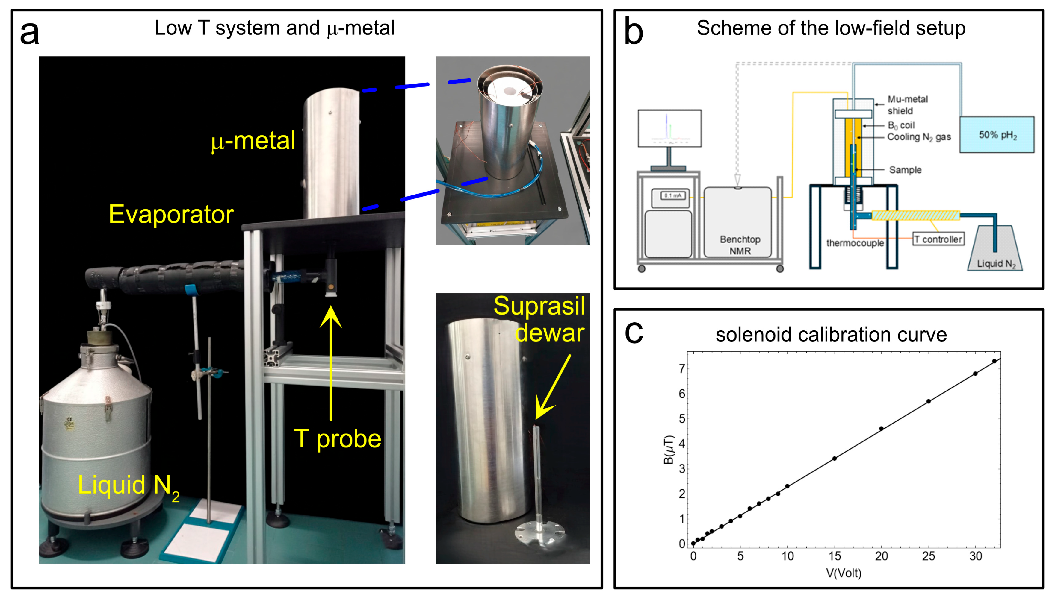
2.3. The Temperature Control unit and Mu-Metal for SABRE-SHEATH Experiments

The temperature control unit consists of a Wilmad suprasil VT dewar (see Figure 3a). This insert (outer diameter 10.5 mm; lower section length 242 mm; upper section length 72 mm) is constructed from high-purity Suprasil® fused silica (quartz glass). It is designed as a non-silvered, unslotted insert, offering excellent optical purity, structural stability, and very low thermal expansion over a broad temperature range (rating from ~120 K up to ~600 K in standard use). In our experimental setup (see Scheme in Figure 3b), this Suprasil VT Dewar is connected to a liquid-nitrogen reservoir via an evaporator. At the bottom of the suprasil dewar a thermocouple measures the temperature (T probe in Figure 3a). The temperature probe is mounted to be in contact with the outer wall of the NMR tube to monitor the temperature of the gas directly. That sensor is interfaced with an external control unit Bruker BVT2000 which dynamically adjusts the flow of N2 gas from the evaporator to regulate the temperature. Through this feedback scheme, we have observed temperature stability better than ± 0.1 K over periods of several hours. The Wilmad dewar is placed at the centre of the µ-metal shield (Sas Ateliers Soudupin, Zero gauss chamber, model: ZG-100-300-3-0 with 3 layers μ-metal thickness 1mm internal diameter : 100 mm length : 300 mm) which contains a solenoidal coil (364 turns of 1 mm copper wire wound in two layers for a total length of 18.5 cm) coupled via a 10 kΩ resistance to DC power supply (model Keysight E36231A) (Figure 3a) to generate the requested magnetic field for hyperpolarization experiments. Wilmad suprasil VT dewar is connected to a liquid nitrogen tank via an evaporator line. The sub microtesla magnetic field necessary for SABRE-SHEATH experiments was measured via a flux gate magnetometer (Bartington – MAG-03MC 1000 and Bartington MAGMETER 2). The calibration curve in Figure 3c was performed returning a good linearity between the applied voltage and the measured magnetic field.

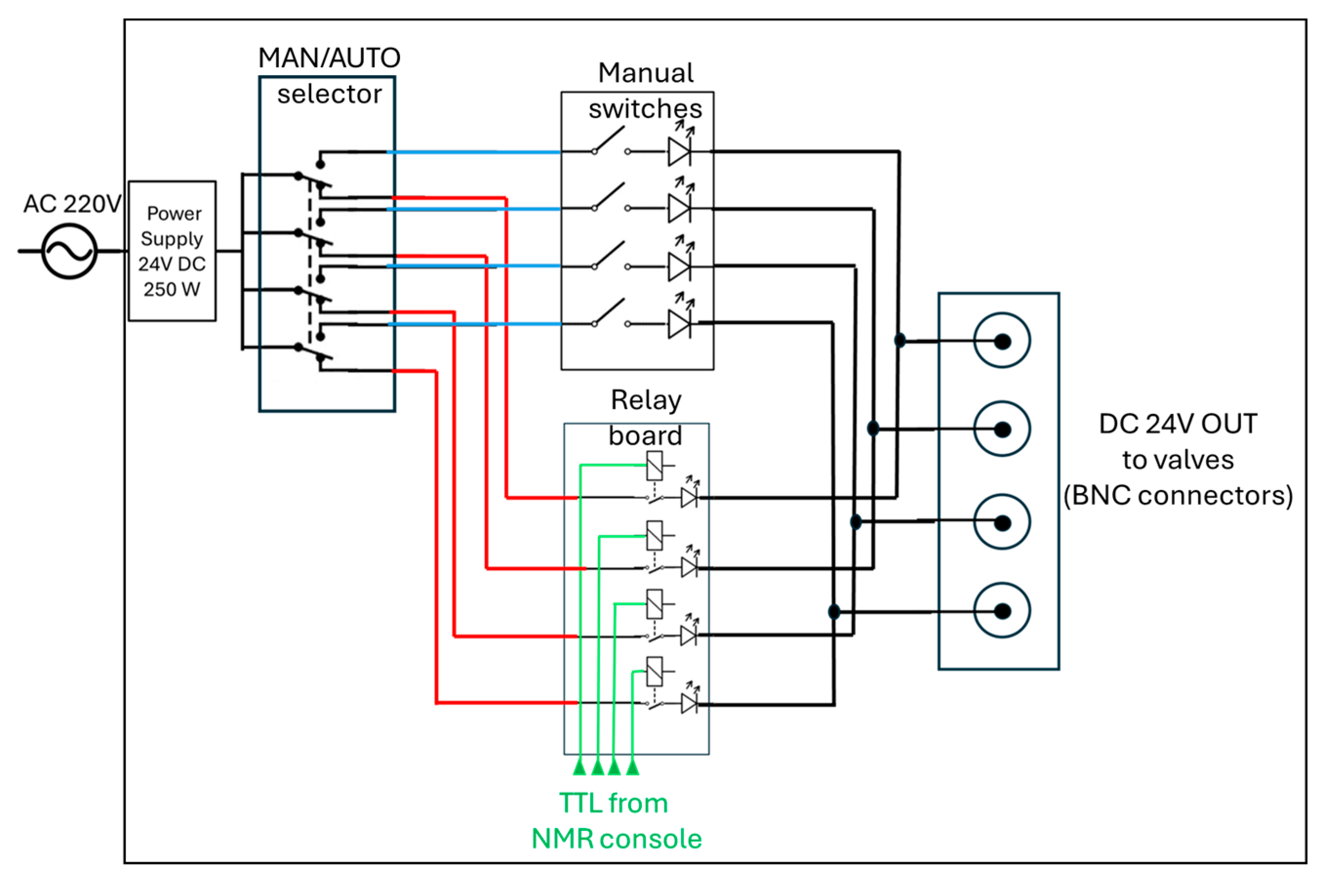
2.4. How to Cable the for Automatic Parahydrogen Experiments at High Magnetic Fields

To perform high-field NMR experiments (i.e. 9.4 T for us), it is advantageous to employ a controlled bubbling system that can be directly operated and regulated by the pulse program initiating the NMR experiment itself. Here, we describe how the TTL output lines of the Bruker NMR console were used to control the state of the solenoid valves via the custom-built switch box shown in Figure 1c(4). In our setup, the Bruker Ascend 400 MHz spectrometer equipped with an Avance III NanoBay console provides four TTL output channels that can serve as trigger signals to control the solenoid valves. Since three valves were required for our system, only three of these lines were utilized. According to the Bruker manual (IPSO AQS Unit Technical Manual), several TTL lines—depending on the specific console configuration—can be assigned to transmit or receive trigger signals.
The implementation simply requires connecting the corresponding console pins to the switch box via BNC cables and editing the Avance.incl file to define the logical state (HIGH or LOW) of each valve during the pulse sequence execution. Once this configuration is established, the valve state can be controlled directly within the TopSpin pulse program by inserting the instruction TTL1 HIGH or TTL1 LOW for the valve associated with trigger 1 (and similarly for the trigger 2 and 3). Example of a pulse sequence used for bubbling and detection is provided in the Appendix B.
For Bruker NMR users, the first step is to consult the table listing the pin assignments for the RCP and Control signals of the T-controller on the IPSO AQS (see Table 4 in the Avance III NanoBay IPSO AQS Unit Technical Manual). In our setup, the console allows sending an output signal through pin V6. Table 3 of the same manual identifies the V bundle and the corresponding V6 pin. The signal from this pin can be routed through a BNC connector cable and coupled to the output of the switch box illustrated in Figure 1c,e, and Figure 2. To correctly use the V6 pin as a trigger output, the Avance.incl file must be modified. First, locate the Avance.incl file; then, refer to the appropriate Table in the Avance III NanoBay IPSO AQS Unit Technical Manual to find the setnmr number corresponding to the desired pin, and define the TTL line accordingly, as described in the Bruker manual. For instance, in our case the Avance.incl is located at: C:\Bruker\TopSpin3.7.0\exp\stan\nmr\lists\pp, and the TTL line for pin V6 can be defined as follows:
/*trigger outputs 1*/
#define TTL1_LOW setnmr4|14
#define TTL1_HIGH setnmr4^14
A similar syntax has been used for the other TTL lines.

3. Results and Discussion

As a demonstration of the versatility of the setup described above, we present a series of characterization experiments on the SABRE catalyst Ir-SIPr and gold standard Ir-IMes, synthesized in our laboratory. The Ir-SIPr complex features an NHC ligand bearing 2,6-diisopropylphenyl substituents and lacks the backbone unsaturation typical of its analog IPr. Together, these catalysts proved to be alternatives to the benchmark Ir-IMes, which remains, however, the best performing NHC catalyst at the moment [46]. The sample was prepared as detailed in the Materials and Methods section.
Figure 4. Pyruvate hyperpolarization by SABRE. Free pyruvate (4) is obtained as a reversible process via [Ir(H)22-pyruvate)(DMSO)(NHC)] (3), whereas hydrogen exchange is mediated by ([IrCl(H)2(DMSO)2(NHC)]) (2) as detailed by Duckett et al. in ref.47,48.
Preprints 180443 g004
The SABRE mechanism for pyruvate follows the description by Duckett and co-workers [47,48]. The NHC precatalyst (either Ir-SIPr or Ir-IMes) (1) is activated in methanol-d4 under a continuous parahydrogen flow (≈30 sccm) at 6 bar, with the activation times estimated below for Ir-IMes at 265 K (see Figure 5c). The co-ligand DMSO, at an optimal 5 equivalent concentration with respect to the catalyst, is instrumental to the reversible pyruvate to catalyst binding. In absence of co-ligand no pyruvate hyperpolarization is observed. Upon binding, the resulting sulfoxide complexes [Ir(H)₂(κ²-pyruvate)(DMSO)(NHC)] (3) (see Figure 4) act as the active polarization-transfer species for ¹³C-pyruvate, while [IrCl(H)₂(DMSO)₂(NHC)] (2) (see Figure 4) mediates hydrogen exchange. Two coordination geometries can be identified for pyruvate binding: 3a (axial) and 3b (equatorial).

3.1. Experiments at 1.4 T with a Benchtop NMR and at 9.4 T

Here we report SABRE-SHEATH experiments conducted at 1.4 T and complementary 1H and 13C measurements at 9.4 T using Ir–SIPr and Ir–IMes catalysts with the setup described above.
Differences between NHC–Ir catalysts can be rationalized in terms of their electronic and steric properties [49,50]. The Tolman Electronic Parameter (TEP) [51], derived from ν(CO) stretching frequency in [Ni(CO)₃L], and the Huynh Electronic Parameter (HEP) [52], obtained from the ¹³C chemical shift of the carbene carbon in [PdBr₂(NHC)(pyridine)], respectively report on the σ-donor/π-acceptor balance and σ-donor strength of a given NHC ligand. Additional probes such as the 77Se NMR shift of NHC–Se adducts or the 13C shift of the free carbene carbon provide complementary information on the electronic density at the metal center.
Steric effects are usually quantified by the percent buried volume (%Vbur), which describes the fraction of the coordination sphere occupied by the ligand, or, less commonly, by the Tolman cone angle, which represents the solid angle subtended by the ligand at the metal center. Taken together, these descriptors explain the distinct behavior of Ir–IMes and Ir–SIPr complexes, the latter being both a stronger σ-donor and more sterically demanding.
In SABRE-SHEATH, when bubbling is performed at the level-anticrossing (LAC) magnetic field (~0.33 μT), polarization is spontaneously transferred from parahydrogen to the J-coupled ¹³C nuclei. As a result, two main classes of signals are observed: one corresponding to the free substrate (4 in Figure 4) and up to two associated with substrate molecules bound to the catalyst (3a and 3b in Figure 4).
This behavior reflects the sterically constrained dynamics imposed by the bulky diisopropylphenyl groups of the SIPr ligand, which hinder formation or stabilization of the 3a isomer. A similar trend was found for the unsaturated analogue Ir–IPr, consistent with earlier observations linking ligand rigidity and donor strength to SABRE efficiency [48].
Figure 5a shows the temperature dependence of the 13C hyperpolarization for Ir–SIPr between 240 K and 305 K. Each sample was bubbled with parahydrogen for 25 s at 6 bar and 80 sccm, then manually transferred in 3 s to the 60 MHz benchtop NMR system for a 90° 13C pulse and signal acquisition. A 10 min delay between experiments allowed full thermal equilibration. The temperature at which each species reaches its maximum signal intensity—260 K for the bound 3b and 272.5 K for free pyruvate—highlights the distinct exchange dynamics governing carbon hyperpolarization.
Precise timing of the bubbling process, enabled by the switch box, allows accurate estimation of the build-up time for 13C polarization. Figure 5b reports experiments at 280 K, 6 bar, and 80 sccm with bubbling times from 1 s to 180 s. Integration of the free pyruvate (left peak in sub panel 5b) and equatorially bound 3b (right peak in sub panel 5b) peaks yields build-up times of 33.8 ± 3.8 s and 16.8 ± 3.3 s, respectively.
In addition, the effect of parahydrogen pressure at different temperatures was investigated for Ir-IMes, as shown in Figure 5c,d. The concentration of H₂ in methanol-d₄ solutions is expected to increase linearly with pressure within the explored temperature range [53]. Consistently, the signals corresponding to both free pyruvate (4) and the equatorially bound species (3b) increase with pressure, although the overall enhancement in signal intensity from 2 bar to 6 bar is only about 20%. However, the pressure dependence of the hyperpolarized signal can be significantly steeper for ¹H species, underscoring the importance of accurately controlling this parameter.
The switch box (see Figure 1c,e,f and Figure 2) can be either operated manually as for the experiments at 1.4 T or automatically via Topspin pulse program as for the experiments at 9.4 T. It enables precisely controlled bubbling directly inside the NMR probe at high magnetic field. Again, we tested the system using Ir-SIPr and the Ir-IMes catalysts. We first monitored the ¹H hydride signal as a function of bubbling time to assess catalyst activation at 265 K, and once the catalyst activation was achieved, we investigated the polarization transfer from hydrides to carbon via the SEPP-INEPT pulse sequence [54,55,56].
When the spectra at 9.4 T are normalized to the most intense resonance in the 0–10 ppm range, two conclusions emerge. (i) Ir-SIPr exclusively exhibits 3b hydrides (hydride protons corresponding to 3b at around -27.2 ppm and -29.1 ppm) consistently with what we found in Figure 5a,b, while Ir-IMes shows both 3a (hydride protons corresponding to 3a at around -24.0 ppm and -14.9 ppm) and 3b species (hydride protons corresponding to 3b at around -27.2 ppm and -29.1 ppm) together with signals from 2 (hydride protons corresponding to 2 at around -15.5 ppm and -21.5 ppm), consistently with what already reported in literature [46]. (ii) The integrated intensities of the 3b hydrides indicate a ratio of approximately 6.7 between Ir-IMes and Ir-SIPr (Figure 6a,b), with an activation time for Ir-IMes of ~1 min at 265 K and 6 bar pressure (Figure 6c).
Overall, these results show that stronger σ-donation and steric bulk in Ir-SIPr stabilize hydride species but limit exchange dynamics, reducing pyruvate hyperpolarization efficiency. In contrast, the less hindered IMes ligand promotes faster exchange between 3a, 3b, and 2, leading to higher polarization transfer at comparable conditions.
This mechanistic understanding also underscores the value of precisely controlled and automated experimental conditions, as subtle differences in ligand dynamics can only be probed reliably when gas flow, timing, and field exposure are accurately synchronized.
Building on these findings, the experimental setup allows polarization-transfer experiments at high magnetic field (9.4 T for us) to be conducted in a fully automated mode, offering the possibility to explore pulse sequences designed to convert hydride-derived two-spin order into heteronuclear magnetization. In particular, polarization can be transferred between the longitudinal two-spin order I1zI2z (where I1 and I2 denote the nuclear hydrides’ spin) and the heteronuclear spin Sx, the transverse spin operator associated to ¹³C in [1-¹³C]pyruvate) (Figure 6e).
One such experiment is the SEPP-INEPT sequence (Figure 6e), recently analyzed by Assaf et al. [54], which enables controlled transfer of hydride polarization to 13C. Without delving into technical details, the sequence converts hydride magnetization into 13C coherence, and the intensity of the resulting bound-form 13C signal depends on the hydride–13C J-coupling and the evolution delay τ2. Using the automated switch box, we implemented this sequence to acquire 13C spectra. For Ir-IMes, the polarization of the 3b species was sufficiently high to detect the bound 13C resonance at 168.5 ppm (τ1 = 20 ms, τ2 = 60 ms), which can be compared to the one-pulse-detection 13C spectrum showing the free pyruvate signal at ~170 ppm (Figure 6e). In contrast, for Ir-SIPr, no detectable ¹³C signal was observed, consistent with the lower polarization level of the 3b form evident in Figure 6a,b. The 2SyFz operator, antiphase magnetization on 13C spin, present before the 90° pulses on ¹H and ¹³C is modulated by the J coupling between the two hydrides during τ1, and by the J coupling between one of the hydrides and 13C during τ2. By fixing τ1 at 20 ms and varying τ2 between 10 ms and 600 ms, we can, as introduced by Assaf et al. [54], estimate the heteronuclear J coupling. The signal is overall modulated according to the function Sin[2π JSF τ2] × Exp[–2 τ2 R], where R represents the relaxation rate. The blue fitting in Figure 6e employing the above function, yields a J coupling between the hydride at –29.1 ppm and the 13C nucleus of bound (3b) pyruvate of approximately ~1.3 Hz. This value should be regarded as an estimate, whose accuracy can be improved by increasing the number of τ₂ points used in the experiment.
These results confirm that efficient hydride–substrate exchange dynamics are a prerequisite for detectable heteronuclear polarization transfer, highlighting how the interplay between electronic donation and steric hindrance dictates both catalytic activity and polarization efficiency.

4. Materials and Methods

A solution containing 6 mM Ir-NHC catalyst, 20 mM sodium [1-13C]pyruvate (Merck SRL, CAS: 87976-71-4) and 30 mM DMSO is prepared in methanol-d4. In the case of 1.4 T experiments the sample was bubbled with 50% parahydrogen at 6 bars for 20 minutes at ambient temperature for catalyst activation. In the case of 9.4 T experiments the sample was prepared in an identical way but the activation was followed by repeated bubbling for 20 seconds for Ir-IMes. The Ir-SIPr and Ir-IMes were synthesized as described in the SI of reference [46]

5. Conclusions

We have presented a cost-effective and versatile setup for performing parahydrogen-based hyperpolarization experiments at 50% parahydrogen enrichment under precisely controlled pressure, temperature, and flow conditions. The system integrates a custom-built switch box that can be operated either manually or automatically through TTL triggers directly synchronized with the NMR console, thus enabling fully automated experiments at high magnetic field. The design is compatible with both benchtop and superconducting NMR instruments, extending the applicability of PHIP and SABRE techniques across a broad range of operating conditions.
The functionality of the setup has been demonstrated by investigating the hyperpolarization of sodium [1-¹³C]pyruvate in methanol-d4 using Ir-SIPr and Ir-IMes as catalysts. At 1.4 T, we performed variable-temperature experiments in manual mode using both Ir-SIPr and Ir-IMes, while precisely controlling the bubbling time and maintaining temperature stability within ±0.1 K. For Ir-IMes, we further explored the dependence of the hyperpolarized signal not only on temperature but also on bubbling pressure, revealing the expected direct correlation between pressure and signal intensity.
At 9.4 T the activation of Ir-IMes catalyst was investigated at 265 K where we estimated to about 1 min the build-up time of the polarization via the hydrides signals. In addition, polarization transfer experiments from hydrides to 13C via the SEPP-INEPT sequence were demonstrated. Through the SEPP-INEPT sequence we have estimated the heteronuclear J interaction between one of the hydride and carbon 13 in 3b form to be in the 1 Hz range. Beyond demonstrating the feasibility of heteronuclear polarization transfer under SABRE conditions, the ability to run automated SEPP-INEPT experiments enables systematic optimization and quantitative analysis of spin transfer pathways, offering direct insight into the nature and dynamics of the active catalytic species.
Overall, the proposed system provides an accessible, reproducible, and scalable platform for PHIP and SABRE studies. By combining mechanical simplicity with electronic automation, it facilitates systematic investigations of catalyst performance and polarization dynamics—thereby contributing to the broader adoption and standardization of parahydrogen hyperpolarization methods in both research and teaching laboratories.

Author Contributions

Conceptualization, G.S.; methodology, G.S., F.F., A. F., L.F., M. R., S.M., C. T.; formal analysis, G.S.; investigation, F.F., A. F., G. S., L. F., M. R., C. T.; writing—original draft preparation, G.S.; writing—review and editing, G.S., F.F., A. F., L.F., M. R., S.M., C. T.; supervision, G.S., C.T.; project administration, G. S.; funding acquisition, G.S and C.T. . All authors have read and agreed to the published version of the manuscript.

Funding

This research has been funded/co-funded by the European Union (ERC StG, HYPMET, 101117082). Views and opinions expressed are however those of the author(s) only and do not necessarily reflect those of the European Union or the European Research Council. Neither the European Union nor the granting authority can be held responsible for them.

Institutional Review Board Statement

Not applicable.

Data Availability Statement

NMR data for this article are available at Zenodo at https://doi.org/. (to be completed upon acceptance).

Acknowledgments

GS acknowledges the internal mechanical and electrical workshop, specifically Lorenzo Dainese, Roberto Inilli and Claudio Comaron for their assistance in building the parahydrogen generator and the distribution system. GS also acknowledges Prof. Fabrizio Mancin and Prof. Federico Rastrelli from Università degli Studi di Padova (IT) for the use of the XPulse benchtop NMR spectrometer.

Conflicts of Interest

The authors declare no conflicts of interest.

Abbreviations

The following abbreviations are used in this manuscript:
PHIP Parahydrogen Induced Hyper Polarization
SABRE Signal Amplification By Reversible Exchange
DNP Dynamic Nuclear Polarization

Appendix A. Estimated Component Costs for the Parahydrogen Generator and Control System

We include a list of materials for parahydrogen generator:
ITEM NAME Q. ESTIMATED PRICE/€
H2 GENERATOR AD-600 Cinel SRL 1 6000.00
Iron(III) oxide catalyst Merck, 371254-50G, 30–50 mesh, CAS 20344-49-4 1 120.00
LN2 Dewar ISOTHERM DSS 2000 1 430.00
Mu-metal Shield Zero gauss chamber, model: ZG-100-300-3-0 1 3800.00
Back pressure regulator ROMETEC SRL 1 500.00
Mass Flow Controller Sierra Instruments C100 1 2300.00
Portable H2 gas detector RS COMPONENTS - RS GD38 1 150.00
Filters M6A-F4L-50-SS RS COMPONENTS 2 250.00
Solenoid valves SMC SMVDW20HA 6 180.00
Safety relief valve S-Lok SRV30-S-6M 1 160.00
Ball valve S-Lok SBV1-S-6M 2 150.00
Tube fitting S-Lok SNV2-S-6M 2 130.00
Two-way ball valve S-Lok SBV1-3B-S-6M 1 90.00
Soft copper 4 mm O.D. -15 m- 1 25.00
Soft copper 6 mm O.D. -15 m- 1 40.00
SMC pneumatic fitting RS COMPONENTS - 771-5920 10 30.00
Flow regulators RS COMPONENTS – 748-0712 10 90.00
Pressure gauge MANS063010BR04NG 4 80.00
Pressure regulators RS COMPONENTS – 204-0053 4 150.00
Nickel-plated brass compression fittings TECNOCAM 10 20.00
Capillary fiber TUBING .010" ID SILICA 1=10M 1 120.00
Tubing PTFE, Polyurethane, nylon 1 100.00
Push in fittings RS COMPONENTS 121-6243 1 35.00
Push in fittings RS COMPONENTS 364-190 1 40.00
Relays DC 24 V 4-Channel Relay Module with Optocoupler Isolation 1 10.00
Power supply 24V, 250 W V-TAC 3273 1 25.00
Push Buttons with LED 16 mm Self-Locking Push Button Switch, 12–24 V, 3 A 4 50.00
Cables and other components 1 150.00
TOTAL 15260.00 - (including hydrogen generator; excluding NMR hardware)

Appendix B. Pulse Sequence for Automated Bubbling and Acquisition

We include below, for completeness, the pulse program that can be used to perform a bubbling and acquisition at high magnetic field.
;zgPHIP.gs : pulse sequence to perform automatized bubbling and acquisition
;avance-version (2/10/18)
;$CLASS=HighRes
;$DIM=1D
;$TYPE=
;$SUBTYPE=
;$COMMENT=
#include <Avance.incl>
#include <Delay.incl>
#include <Grad.incl>
"p2=p1*2"
"p4=p3*2"
; Definitions
;;;;;;;;;;;;;;;;;;;;;;;;;;;;;;;;;;;;;;;;;;;;;
define delay dByPass
"dByPass=cnst2"
define delay dPressurization
"dPressurization=cnst3"
define delay dBubbling
"dBubbling=cnst4"
define delay dExhaust
"dExhaust=cnst5"
define delay dStabilization
"dStabilization=cnst6"
;;;;;;;;;;;;;;;;;;;;;;;;;;;;;;;;;;;;;;;;;;;;;
; Pulse sequence
1 ze
2 30m
d1
; Operations at the switch box
TTL1_HIGH ; Set the "By Pass" valve to off
TTL2_HIGH ; Set the "pH2" valve to off
TTL3_HIGH ; Set the "Exhaust" valve to off
TTL4_HIGH ; Set the "N2" valve to off
dByPass TTL1_LOW ; Activate "By Pass Valve"
2s
dPressurization TTL2_LOW ; Pressurization with pH2
dBubbling TTL1_HIGH ; Bubbling Period
TTL1_LOW ; Stop bubbling
1s
TTL2_HIGH ; Stop pH2
;;;;;;;;;;;;;;;;;;;;;;;;;;;;;;;;;;;;;;;;;;;;;
dStabilization ; Stabilization after bubbling
4u pl1:f1 ;power on F1
(p1 ph1):f1
go=2 ph31
30m mc #0 to 2 F0(zd)
100m
dExhaust TTL3_LOW ; Release pressure
TTL3_HIGH
TTL1_HIGH
exit
ph1 = 1
ph31 = 0
;pl1 : f1 channel - power level for pulse (default) HETERONUCLEAR
;pl2 : f2 channel - power level for pulse (default) PROTON
;p1 : f1 channel - 90 degree high power pulse HETERONUCLEAR
;p2 : f1 channel - 180 degree high power pulse HETERONUCLEAR
;p3 : f2 channel - 90 degree high power pulse PROTON
;p4 : f2 channel - 180 degree high power pulse PROTON
;d1 : relaxation delay
;cnst2 : switch on ByPass Valve (1s is OK)
;cnst3 : Pressurization of the system (>120s)
;cnst4 : Bubbling time
;cnst5 : Exhaust time
;cnst6 : Stabilization after bubbling
Comments:
In zgPHIP.gs, dByPass defines the duration for which the bypass valve is activated, while dPressurization specifies the time required for the system to reach the desired pressure, depending on the mass flow controller settings. dBubbling corresponds to the bubbling duration, and dStabilization represents the delay time allowed for the bubbles to dissipate and the system to reach equilibrium before acquisition.

References

  1. Luchinat, E.; Cremonini, M.; Banci, L. Radio Signals from Live Cells: The Coming of Age of In-Cell Solution NMR. Chem. Rev. 2022, 122, 9267–9306. [CrossRef]
  2. Sakakibara, D.; Sasaki, A.; Ikeya, T.; Hamatsu, J.; Hanashima, T.; Mishima, M.; Yoshimasu, M.; Hayashi, N.; Mikawa, T.; Wälchli, M.; et al. Protein structure determination in living cells by in-cell NMR spectroscopy. Nature 2009, 458, 102–105. [CrossRef]
  3. Gallagher, F.A.; Bohndiek, S.E.; Kettunen, M.I.; Lewis, D.Y.; Soloviev, D.; Brindle, K.M. Hyperpolarized 13C MRI and PET: In Vivo Tumor Biochemistry. J. Nucl. Med. 2011, 52, 1333–1336. [CrossRef]
  4. Abragam A. Principles of nuclear magnetism. Clarendon Press, Oxford; 1961.
  5. Gadian, D.G.; Panesar, K.S.; Linde, A.J.P.; Horsewill, A.J.; Köckenberger, W.; Owers-Bradley, J.R. Preparation of highly polarized nuclear spin systems using brute-force and low-field thermal mixing. Phys. Chem. Chem. Phys. 2012, 14, 5397–5402. [CrossRef]
  6. Owers-Bradley JR, Horsewill AJ, Peat DT, Goh KSK, Gadian DG. High polarization of nuclear spins mediated by nanoparticles at millikelvin temperatures. Phys Chem Chem Phys. 2013;15(25):10413.
  7. Hirsch, M.L.; Kalechofsky, N.; Belzer, A.; Rosay, M.; Kempf, J.G. Brute-Force Hyperpolarization for NMR and MRI. J. Am. Chem. Soc. 2015, 137, 8428–8434. [CrossRef]
  8. Peat, D.T.; Hirsch, M.L.; Gadian, D.G.; Horsewill, A.J.; Owers-Bradley, J.R.; Kempf, J.G. Low-field thermal mixing in [1-13C] pyruvic acid for brute-force hyperpolarization. Phys. Chem. Chem. Phys. 2016, 18, 19173–19182. [CrossRef]
  9. Kovacs, H.; Moskau, D.; Spraul, M. Cryogenically cooled probes—a leap in NMR technology. Prog. Nucl. Magn. Reson. Spectrosc. 2005, 46, 131–155. [CrossRef]
  10. Jones, C.J.; Larive, C.K. Could smaller really be better? Current and future trends in high-resolution microcoil NMR spectroscopy. Anal. Bioanal. Chem. 2011, 402, 61–68. [CrossRef]
  11. Overhauser AW. Polarization of Nuclei in Metals. Phys Rev. 1953 Oct 15;92(2):411–5.
  12. Carver, T.R.; Slichter, C.P. Polarization of Nuclear Spins in Metals. Phys. Rev. B 1953, 92, 212–213. [CrossRef]
  13. Eills, J.; Budker, D.; Cavagnero, S.; Chekmenev, E.Y.; Elliott, S.J.; Jannin, S.; Lesage, A.; Matysik, J.; Meersmann, T.; Prisner, T.; et al. Spin Hyperpolarization in Modern Magnetic Resonance. Chem. Rev. 2023, 123, 1417–1551. [CrossRef]
  14. Henstra, A.; Dirksen, P.; Wenckebach, W. Enhanced dynamic nuclear polarization by the integrated solid effect. Phys. Lett. A 1988, 134, 134–136. [CrossRef]
  15. Ardenkjaer-Larsen, J.H.; Fridlund, B.; Gram, A.; Hansson, G.; Hansson, L.; Lerche, M.H.; Servin, R.; Thaning, M.; Golman, K. Increase in signal-to-noise ratio of > 10,000 times in liquid-state NMR. Proc. Natl. Acad. Sci. USA 2003, 100, 10158–10163. [CrossRef]
  16. Wenckebach WT. The Solid Effect. Appl Magn Reson. 2008 Aug;34(3–4):227.
  17. Lesage, A.; Lelli, M.; Gajan, D.; Caporini, M.A.; Vitzthum, V.; Miéville, P.; Alauzun, J.; Roussey, A.; Thieuleux, C.; Mehdi, A.; et al. Surface Enhanced NMR Spectroscopy by Dynamic Nuclear Polarization. J. Am. Chem. Soc. 2010, 132, 15459–15461. [CrossRef]
  18. Jannin, S.; Bornet, A.; Colombo, S.; Bodenhausen, G. Low-temperature cross polarization in view of enhancing dissolution Dynamic Nuclear Polarization in NMR. Chem. Phys. Lett. 2011, 517, 234–236. [CrossRef]
  19. Corzilius B. Theory of solid effect and cross effect dynamic nuclear polarization with half-integer high-spin metal polarizing agents in rotating solids. Phys Chem Chem Phys. 2016;18(39):27190–204.
  20. Wenckebach WTh. Dynamic nuclear polarization via thermal mixing: Beyond the high temperature approximation. J Magn Reson. 2017 Apr;277:68–78.
  21. Bowers, C.R.; Weitekamp, D.P. Transformation of Symmetrization Order to Nuclear-Spin Magnetization by Chemical Reaction and Nuclear Magnetic Resonance. Phys. Rev. Lett. 1986, 57, 2645–2648. [CrossRef]
  22. Bowers CR, Weitekamp DP. Para-Hydrogen and Synthesis Allow Dramatically Enhanced Nuclear Alignment. J Am Chem Soc. 1987 Sept 2;109(18):5541–2.
  23. Natterer J, Bargon J. Parahydrogen induced polarization. Prog Nucl Magn Reson Spectrosc. 1997 Nov;31(4):293–315.
  24. Koptyug, I.V.; Kovtunov, K.V.; Burt, S.R.; Anwar, M.S.; Hilty, C.; Han, S.-I.; Pines, A.; Sagdeev, R.Z. para-Hydrogen-Induced Polarization in Heterogeneous Hydrogenation Reactions. J. Am. Chem. Soc. 2007, 129, 5580–5586. [CrossRef]
  25. Adams, R.W.; Aguilar, J.A.; Atkinson, K.D.; Cowley, M.J.; Elliott, P.I.P.; Duckett, S.B.; Green, G.G.R.; Khazal, I.G.; López-Serrano, J.; Williamson, D.C. Reversible Interactions with para-Hydrogen Enhance NMR Sensitivity by Polarization Transfer. Science 2009, 323, 1708–1711. [CrossRef]
  26. Atkinson, K.D.; Cowley, M.J.; Elliott, P.I.P.; Duckett, S.B.; Green, G.G.R.; López-Serrano, J.; Whitwood, A.C. Spontaneous Transfer of Parahydrogen Derived Spin Order to Pyridine at Low Magnetic Field. J. Am. Chem. Soc. 2009, 131, 13362–13368. [CrossRef]
  27. Kauczor, H.-U.; Surkau, R.; Roberts, T. MRI using hyperpolarized noble gases. Eur. Radiol. 1998, 8, 820–827. [CrossRef]
  28. Meier B, Dumez JN, Stevanato G, Hill-Cousins JT, Roy SS, Hakansson P, et al. Long-lived nuclear spin states in methyl groups and quantum-rotor-induced polarization. J Am Chem Soc. 2013 Dec 18;135(50):18746–9.
  29. Dumez, J.-N.; Vuichoud, B.; Mammoli, D.; Bornet, A.; Pinon, A.C.; Stevanato, G.; Meier, B.; Bodenhausen, G.; Jannin, S.; Levitt, M.H. Dynamic Nuclear Polarization of Long-Lived Nuclear Spin States in Methyl Groups. J. Phys. Chem. Lett. 2017, 8, 3549–3555. [CrossRef]
  30. Corzilius, B.; Smith, A.A.; Barnes, A.B.; Luchinat, C.; Bertini, I.; Griffin, R.G. High-Field Dynamic Nuclear Polarization with High-Spin Transition Metal Ions. J. Am. Chem. Soc. 2011, 133, 5648–5651. [CrossRef]
  31. Corzilius B. Theory of solid effect and cross effect dynamic nuclear polarization with half-integer high-spin metal polarizing agents in rotating solids. Phys Chem Chem Phys. 2016 Oct 5;18(39):27190–204.
  32. Corzilius, B. High-Field Dynamic Nuclear Polarization. Annu. Rev. Phys. Chem. 2020, 71, 143–170. [CrossRef]
  33. Jardón-Álvarez, D.; Leskes, M. Metal ions based dynamic nuclear polarization: MI-DNP. Prog. Nucl. Magn. Reson. Spectrosc. 2023, 138-139, 70–104. [CrossRef]
  34. Javed, A.; Jabbour, R.; Sadasivan, S.V.; Alsaghir, S.; Alhussni, A.; Jhamnani, M.; Equbal, A. Dynamic nuclear polarization: State of the art and future possibilities with light activation. Chem. Phys. Rev. 2025, 6. [CrossRef]
  35. Albers, M.J.; Bok, R.; Chen, A.P.; Cunningham, C.H.; Zierhut, M.L.; Zhang, V.Y.; Kohler, S.J.; Tropp, J.; Hurd, R.E.; Yen, Y.-F.; et al. Hyperpolarized 13C Lactate, Pyruvate, and Alanine: Noninvasive Biomarkers for Prostate Cancer Detection and Grading. Cancer Res. 2008, 68, 8607–8615. [CrossRef]
  36. Capozzi, A.; Hyacinthe, J.-N.; Cheng, T.; Eichhorn, T.R.; Boero, G.; Roussel, C.; van der Klink, J.J.; Comment, A. Photoinduced Nonpersistent Radicals as Polarizing Agents for X-Nuclei Dissolution Dynamic Nuclear Polarization. J. Phys. Chem. C 2015, 119, 22632–22639. [CrossRef]
  37. Reineri, F.; Boi, T.; Aime, S. ParaHydrogen Induced Polarization of 13C carboxylate resonance in acetate and pyruvate. Nat. Commun. 2015, 6, 5858–5858. [CrossRef]
  38. Di Matteo, G.; Bondar, O.; Carrera, C.; Cavallari, E.; Mishra, S.; Reineri, F. Improving the Catalyst Efficiency for Hyperpolarization of Pyruvate Derivatives by Means of Hydrogenative PHIP. ChemMedChem 2025, 20, e202500379. [CrossRef]
  39. Kiryutin, A.S.; Sauer, G.; Hadjiali, S.; Yurkovskaya, A.V.; Breitzke, H.; Buntkowsky, G. A highly versatile automatized setup for quantitative measurements of PHIP enhancements. J. Magn. Reson. 2017, 285, 26–36. [CrossRef]
  40. Birchall JR, Coffey AM, Goodson BM, Chekmenev EY. High-Pressure Clinical-Scale 87% Parahydrogen Generator. Anal Chem. 2020 Dec 1;92(23):15280–4.
  41. Nantogma, S.; Joalland, B.; Wilkens, K.; Chekmenev, E.Y. Clinical-Scale Production of Nearly Pure (>98.5%) Parahydrogen and Quantification by Benchtop NMR Spectroscopy. Anal. Chem. 2021, 93, 3594–3601. [CrossRef]
  42. Chapman, B.; Joalland, B.; Meersman, C.; Ettedgui, J.; Swenson, R.E.; Krishna, M.C.; Nikolaou, P.; Kovtunov, K.V.; Salnikov, O.G.; Koptyug, I.V.; et al. Low-Cost High-Pressure Clinical-Scale 50% Parahydrogen Generator Using Liquid Nitrogen at 77 K. Anal. Chem. 2021, 93, 8476–8483. [CrossRef]
  43. Ellermann, F.; Pravdivtsev, A.; Hövener, J.-B. Open-source, partially 3D-printed, high-pressure (50-bar) liquid-nitrogen-cooled parahydrogen generator. Magn. Reson. 2021, 2, 49–62. [CrossRef]
  44. Schmidt, A.B.; Bowers, C.R.; Buckenmaier, K.; Chekmenev, E.Y.; de Maissin, H.; Eills, J.; Ellermann, F.; Glöggler, S.; Gordon, J.W.; Knecht, S.; et al. Instrumentation for Hydrogenative Parahydrogen-Based Hyperpolarization Techniques. Anal. Chem. 2022, 94, 479–502. [CrossRef]
  45. Duchowny, A.; Denninger, J.; Lohmann, L.; Theis, T.; Lehmkuhl, S.; Adams, A. SABRE Hyperpolarization with up to 200 bar Parahydrogen in Standard and Quickly Removable Solvents. Int. J. Mol. Sci. 2023, 24, 2465. [CrossRef]
  46. Mamone S, Floreani F, Faramawy A, Graiff C, Franco L, Ruzzi M, et al. (De)coding SABRE of [1-13C]Pyruvate. Phys Chem Chem Phys. 2025;10.1039.D5CP01773D.
  47. Tickner, B.J.; Lewis, J.S.; John, R.O.; Whitwood, A.C.; Duckett, S.B. Mechanistic insight into novel sulfoxide containing SABRE polarisation transfer catalysts. Dalton Trans. 2019, 48, 15198–15206. [CrossRef]
  48. Tickner, B.J.; Semenova, O.; Iali, W.; Rayner, P.J.; Whitwood, A.C.; Duckett, S.B. Optimisation of pyruvate hyperpolarisation using SABRE by tuning the active magnetisation transfer catalyst. Catal. Sci. Technol. 2020, 10, 1343–1355. [CrossRef]
  49. Verlinden K, Buhl H, Frank W, Ganter C. Determining the Ligand Properties of N-Heterocyclic Carbenes from 77Se NMR Parameters. Eur J Inorg Chem. 2015 May;2015(14):2416–25.
  50. Clavier, H.; Nolan, S.P. Percent buried volume for phosphine and N-heterocyclic carbene ligands: steric properties in organometallic chemistry. Chem. Commun. 2010, 46, 841–861. [CrossRef]
  51. Tolman CA. Steric effects of phosphorus ligands in organometallic chemistry and homogeneous catalysis. Chem Rev. 1977 June 1;77(3):313–48.
  52. Teng, Q.; Huynh, H.V. A unified ligand electronic parameter based on 13C NMR spectroscopy of N-heterocyclic carbene complexes. Dalton Trans. 2016, 46, 614–627. [CrossRef]
  53. Descamps, C.; Coquelet, C.; Bouallou, C.; Richon, D. Solubility of hydrogen in methanol at temperatures from 248.41 to 308.20K. Thermochim. Acta 2005, 430, 1–7. [CrossRef]
  54. Assaf, C.D.; Gui, X.; Auer, A.A.; Duckett, S.B.; Hövener, J.-B.; Pravdivtsev, A.N. J Coupling Constants of <1 Hz Enable 13C Hyperpolarization of Pyruvate via Reversible Exchange of Parahydrogen. J. Phys. Chem. Lett. 2024, 15, 1195–1203. [CrossRef]
  55. Assaf, C.D.; Gui, X.; Salnikov, O.G.; Brahms, A.; Chukanov, N.V.; Skovpin, I.V.; Chekmenev, E.Y.; Herges, R.; Duckett, S.B.; Koptyug, I.V.; et al. Analysis of chemical exchange in iridium N-heterocyclic carbene complexes using heteronuclear parahydrogen-enhanced NMR. Commun. Chem. 2024, 7, 1–10. [CrossRef]
  56. Salnikov, O.G.; Assaf, C.D.; Yi, A.P.; Duckett, S.B.; Chekmenev, E.Y.; Hövener, J.-B.; Koptyug, I.V.; Pravdivtsev, A.N. Modeling Ligand Exchange Kinetics in Iridium Complexes Catalyzing SABRE Nuclear Spin Hyperpolarization. Anal. Chem. 2024, 96, 11790–11799. [CrossRef]
Figure 1. Description of the liquid-nitrogen parahydrogen generator and the gas distribution system. In a) the push-in Y fitting connecting the inlet and outlet gas lines (1), nickel-plated brass compression fittings module (2), PTFE tube (3), NMR tube (4) and quartz capillary for gas bubbling (5). In b) the H2 gas generator (1), the liquid nitrogen vessel (11) that can be lifted to immerse the 6 mm o.d. copper serpentine (10) containing the Iron (III) catalyst for ortho- to parahydrogen conversion; diaphragm pump (12). In c) the distribution system with pressure reg-ulator (1), solenoid valves (2, 6, 7), back pressure regulator (3), Switchbox (4), BNC TTL cables to NMR console (5). In d) expansion of the parahydrogen generator with two-way and single manual ball valve (2, 3), pressure gauge (4), in-line microfilters (5), manual ball valve (6), pressure gauge (7), mass flow controller (8). In e) Top and open view of the switchbox shown in c(4). In f) front view with push button LED of the switch box in c(4).
Preprints 180443 g001
Figure 2. A schematic diagram of the control unit used to drive the solenoidal valves in the parahydrogen distribution section (Figure 1c(4)). The 24V DC used to switch four valves is routed by a manual switch (4PDT) either to a manual control set of buttons (Manual switches) or to an automatic control sytem trough an array of relays (Relay board) controlled by the TTL signals coming from the NMR console (or from any TTL compatible unit, e.g. Arduino). See also Figure 1e,f.
Preprints 180443 g002
Figure 3. In a) Suprasil dewar, μ-metal shield enclosing the solenoid coil to produce the B0 magnetic field in the 0 μT to 10 μT range, , Evaporator with temperature sensor (T-probe) and Liquid N2 dewar. In b) a simplified scheme of the experimental set-up and in d) the calibration curve for the solenoid winding to produce the desired B0 in the μT range...
Preprints 180443 g003
Figure 5. Experiments with Ir-SIPr catalyst. The sample includes 6 mM SIPr, 20 mM sodium [1-13C]pyruvate and 30 mM DMSO for a total volume of 700 μL. The sample was bubbled for 25 s at 6 bars and 80 sccm at 0.35 μT and manually shuttled at 1.4 T for signal detection. The recovery time between experiments was set to 5 minutes. In a) Temperature profile experiments in the range 240 K – 305 K. In b) the bubbling time was varied from 1s to 180s in consecutive experiments to evaluate 13C hyperpolarization build-up kinetics. Ir-IMes temperature profiles in the 240 K to 310 K range at parahydrogen bubbling pressures of 2 (red), 4 (green) and 6 (blue) bars in c) for the free pyruvate form (4) and in d) for the equatorially-bound 3b form.
Preprints 180443 g005
Figure 6. ¹H spectra acquired after 25 s of bubbling 50% parahydrogen with a 45° pulse for the solutions containing Ir–SIPr (a) and Ir–IMes (b). In the shadowed boxe in (a), the signals correspond to species 3b, with hydride resonances observed at approximately –27.2 ppm and –29.1 ppm. In the shadowed boxe in (b), both 3a (hydride protons at –24.0 ppm and –14.9 ppm) and 3b species (hydride protons at –27.2 ppm and –29.1 ppm) are detected, together with signals from species 2 (hydride protons at –15.5 ppm and –21.5 ppm). In c) activation profile of Ir–IMes obtained by progressively bubbling H₂ into the solution and monitoring the hydrides ¹H signal. The data points represent the integrals of one of the two hydride 3b resonances. (d) ¹H spectra of the dissolved H₂ region (≈4.59 ppm) and the hydride region of 3b recorded at increasing flow rates from 7sccm to 105 sccm. (e) SEPP-INEPT pulse sequence with the corresponding quantum operators (I,S indicate hydrides and F indicates 13C) at different steps and ¹³C pulse-acquisition sequence, along with the ¹³C spectra at 265 K for Ir–SIPr and Ir–IMes using τ₁ = 20 ms and τ₂ = 60 ms. By varying τ₂, the integral of the 3b peak is plotted, allowing estimation of the J coupling between the hydride at –29.2 ppm and the ¹³C at 168.5 ppmUsing Ir–SIPr, as shown in our work [46], we clearly detect, by 13C NMR, the free pyruvate signal at ~170 ppm (4) and the equatorially bound species at ~168.5 ppm (3b), while the axially bound pyruvate (3a) appears only as a weak shoulder.
Preprints 180443 g006
Disclaimer/Publisher’s Note: The statements, opinions and data contained in all publications are solely those of the individual author(s) and contributor(s) and not of MDPI and/or the editor(s). MDPI and/or the editor(s) disclaim responsibility for any injury to people or property resulting from any ideas, methods, instructions or products referred to in the content.
Copyright: This open access article is published under a Creative Commons CC BY 4.0 license, which permit the free download, distribution, and reuse, provided that the author and preprint are cited in any reuse.
Prerpints.org logo

Preprints.org is a free preprint server supported by MDPI in Basel, Switzerland.

Subscribe

Disclaimer

Terms of Use

Privacy Policy

Privacy Settings

© 2025 MDPI (Basel, Switzerland) unless otherwise stated