Submitted:
10 October 2025
Posted:
13 October 2025
You are already at the latest version
Abstract
The paper deals with the problem of local instability of sandwich panels, which consist of two thin but relatively stiff facings and a thick but shear-deformable core. Such structures are commonly used in civil engineering, as well as in the aerospace, aviation, and automotive industries. A case is presented when one of the facings is deep-profiled. Due to typical mechanical or thermal interactions, this facing is subjected to compression. The thick core of the sandwich panel plays a stabilizing role; however, at a specific critical load, local stability is lost, which is a typical form of damage in sandwich panels. In the case of a deep-profiled facing, the geometry of the facing must also be taken into account, specifically the fact that the bends resulting from profiling constitute a significant limitation to its deformation. In the paper, expressions are derived that enable the determination of the critical (wrinkling) stress, taking into account the geometry of the compressed facing bands and various boundary conditions defined along their edges. The energy approach will be used to solve the problem. The presented solution to the problem will be illustrated with examples. The obtained results indicate that the use of narrow bands is particularly effective, but they also allow for determining the maximum benefits resulting from deep profiling of the facings. This information is essential when considering changes to the geometry of industrially produced sandwich panels or optimizing the load-bearing capacity of individual sandwich elements.
Keywords:
sandwich panels
; local instability
; wrinkling
; strain energy
1. Introduction
This paper concerns sandwich panels, which consist of two thin, stiff facings and a thick but shear-deformable core. The facings, usually made of metal, serve as protective layers. From a mechanical point of view, their main task is to transfer the normal stresses resulting from the bending of the panel. The core of the panel provides thermal insulation and is made from materials with lower elastic moduli, such as PIR (polyisocyanurate) foam, EPS (expanded polystyrene), or MW (mineral wool). The core is susceptible to deformation, but transfers shear stresses and separates the facings, which gives the panel flexural rigidity.
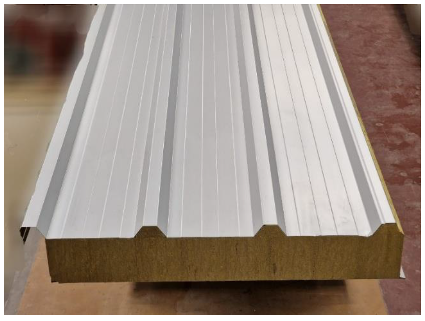
Sandwich panels are a universal solution that combines thermal insulation, lightness, durability, and quick installation. These types of elements are widely used in construction and many other industries, including aviation, space, and automotive. An example of a sandwich panel used for roofing is shown in Figure 1.
Figure 1.
Sandwich panel with deep-profiles steel facing.
The sandwich elements can fail in various ways, but their load-bearing capacity is most commonly limited by local instability, often in the form of wrinkling of the compressed facing. The compressive stress may result from axial compression, bending moments, or thermal effects. Accurately determining the panel's load-bearing capacity requires identifying the critical stress level at which wrinkling occurs.
For decades, researchers have been studying how to predict wrinkling stress in sandwich structures. This is a crucial issue because it plays a critical role in ensuring structural stability. One of the earliest analytical solutions was proposed in [1], where the energy method and a linear decay function were used to describe the core deformation. This approach was developed in [2] by introducing an exponential decay function. In [3], a different approach was used, formulating the wrinkling problem using differential equations.
The classical approaches presented above are still used and extended to more complex problems. The issue of wrinkling of sandwich panels with composite facings under biaxial load was investigated in [4]. The local instability of a thin orthotropic layer was analyzed in [5]. Effects of anisotropy and multiaxial loading on the wrinkling of sandwich panels were discussed in [6]. Another interesting problem is the local instability in the case of a bi-modular core [7]. The stiffness of such a core differs in tension and compression, which obviously affects the structure's behavior. The effect of transverse core compressibility was considered in [8], where the static and dynamic responses of layered structures, including the wrinkling phenomenon, were examined. A similar problem concerning local dynamic instability, i.e., large-amplitude, small-wavelength lateral vibrations, was addressed in [9], where the criterion for the onset of dynamic wrinkling and a critical value of the facing damping coefficient were presented for the elastic foundation model. The damping of sandwich composites, expressed as the logarithmic decrement, damping ratio, and loss factor, can be determined experimentally using the free vibration decay effect, evaluated by the logarithmic decrement and half-power bandwidth methods [10].
The application of the extended high-order sandwich panel theory to the problem of sandwich panels wrinkling was presented in [11]. The authors demonstrated good agreement between the theoretical and experimental results. The behavior of structures with a functionally graded core material in the context of local instability was analyzed in [12]. A new method for predicting the wrinkling stress in sandwich panels was proposed in [13]. This method can be easily applied to compute the wrinkling stress of panels with functionally graded material cores.
Scientific research on wrinkling of thin facing is still of great interest because the problem of local instability is important in many applications. The issue of local buckling in the context of using sandwich panels in light aviation was discussed in [14], where, among other things, experimental methods and failure scenarios were examined. The analysis of sandwich structures, which have been widely applied in the wings and horizontal tails of aircraft, was presented in [15]. This paper proposed a reasonable strategy for resisting wrinkling deformation of sandwich structures. New applications of sandwich structures often necessitate the development of new materials or structural solutions. In [16], structures made of unidirectional carbon/epoxy facings and aluminum honeycomb and closed-cell PVC foam cores were studied. The experimental results confirmed that failure by wrinkling is prevalent in cases of low through-thickness stiffness and long beam spans. According to [17, 18], it is also found that due to the influence of production parameters and operating conditions, extensive experimental studies are necessary to accurately predict sandwich panel damage, enabling the reliable application of advanced models and failure criteria.
Slightly different structures, namely those made of printed PLA, were studied in [19]. Three honeycomb core topologies were subjected to bending: conventional, re-entrant auxetic, and chiral. Different failure mechanisms were identified for each of these structures, including local loss of stability. The problem of the compression behavior of sandwich elements was also discussed in [20]. In this case, an aluminum honeycomb structure filled with ethylene vinyl acetate copolymer foam was investigated.
Both new applications of sandwich panels and the introduction of new material solutions require detailed strength analyses. This is particularly applicable to products manufactured on a large scale. The article addresses the problem of damage to the facing of deep-profiled panels. The inspiration for conducting this research was the expectation of sandwich panel manufacturers regarding the effectiveness of introducing deep-profiled facings. The solution presented in the paper considers the impact of all the most significant parameters of sandwich panels on damage, specifically wrinkling. A novelty in relation to previous theoretical solutions is the use of a two-dimensional model of the facing (band) with the simultaneous possibility of introducing various boundary conditions (including elastic support) on the edges of this band.
2. Formulation of the Problem
The sandwich panel shown in Figure 1 is usually used as a roof covering element placed on purlins. In such a case, the panel is loaded with, among others, its own weight, wind and snow actions, and, which is very important, various thermal impacts. As a result of these loads, a complex state of stress occurs in each component of the sandwich panel (top facing, core, bottom facing). In the facing, tension or compression dominates along the direction of the panel, which results from the bending of the sandwich panel. The purpose of the core is to transfer shear stresses and ensure cooperation between the facings.
This article focuses on the deep-profiled facing (top facing in
Figure 1
). When the facing is stretched, its load-bearing capacity is relatively high. When the facing is compressed, the problem of its local instability occurs. This is due to the high slenderness of the element. The typical thickness of the facing is 0.5 mm, whereas the span of the panel is of the order of 3 m. It is also worth noting that bending the panel shown in
Figure 1
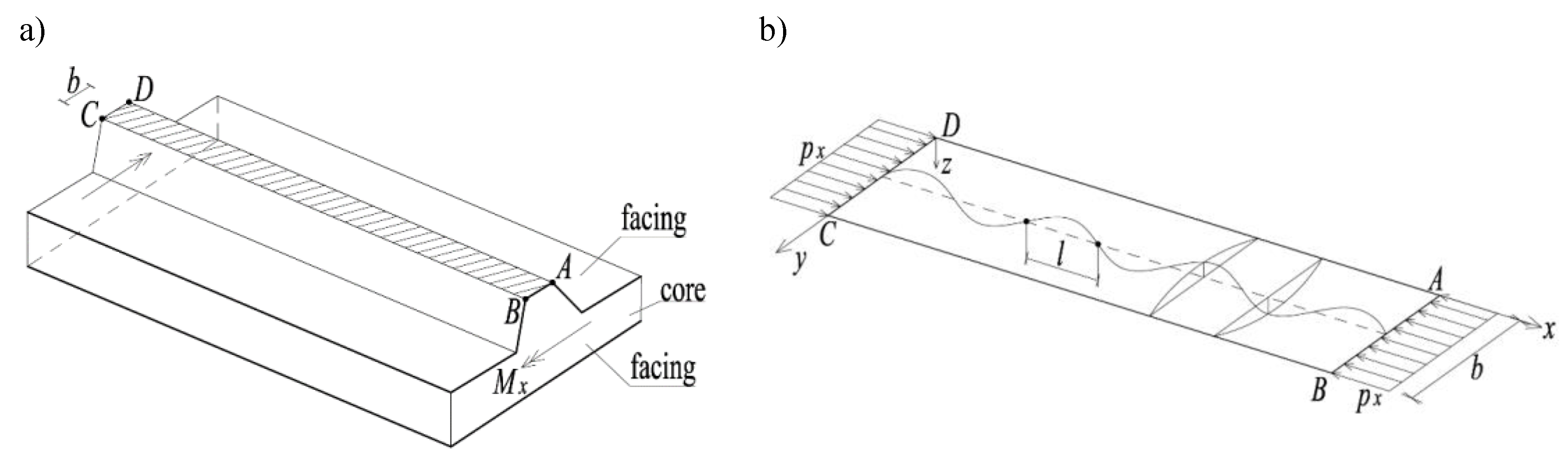
results in the greatest stresses in the parts furthest from the center of the neutral plane, i.e., in the case of a deep-profiled facing – in the narrow ridge bands. One of such bands is marked in
Figure 2
a (band ABCD).
In this paper, the case of a perfectly flat band ABCD, which is uniformly unidirectionally compressed in its plane, is considered. It is assumed that this band rests on an infinite core. Although this assumption may seem controversial at first, numerous studies have confirmed that core deformations disappear very quickly across their thickness. From a practical point of view, it can be assumed that deformations at a depth greater than 2 cm measured from the surface of the compressed facing are negligible [21, 22].
As a result of uniaxial compression of the ABCD band of width , at a specific load , local instability occurs, which has the form of periodic wrinkling (Figure 2b) in the x-direction. The edges of the band limit the form of deformation in the y-direction. The critical load is sought, which causes wrinkling of the facing. Determining this load is essential because the wrinkling phenomenon is the primary failure mechanism of a sandwich panel. The key issue of this paper is to determine the influence of the band width and the support conditions on the longitudinal edges of the analyzed band (BC, AD) on the critical load.
In the analyses, it was assumed that the materials of the facings and the core are homogeneous and that linear constitutive laws are valid. For the sake of generality, it was assumed that the core modulus of elasticity (in the z-direction – perpendicular to the facing plane) is independent of the core shear moduli and (moduli in the x-z and y-z planes, respectively).
Figure 2.
A band of facing (ABCD) being analyzed: a) a section of a deep-profiled sandwich panel, b) deformations of a facing band subjected to uniform, unidirectional compression.
Figure 2.
A band of facing (ABCD) being analyzed: a) a section of a deep-profiled sandwich panel, b) deformations of a facing band subjected to uniform, unidirectional compression.
3. Determination of the Critical Stress
In order to find the critical load px, and the respective critical (wrinkling) stress, the energy approach was used. As in [2, 12], core deformations in the longitudinal direction (along the -direction) were not included in the energy equilibrium equation. The justification for this approach can be found, inter alia, in [23].
Assume, that the facing deformation has a sinusoidal form in the x-direction:
where denotes the amplitude of deformation and is the length of the half-wave of the sine function in the x-direction. The function representing the variation of deformation in the y-direction is given here in an arbitrary form to obtain a possibly general solution. The form of the function should reflect the boundary conditions established for the longitudinal edges of the facing band. In the simplest form corresponding to a simply supported band, .
The core deformation disappears exponentially (), which in a sense justifies the rapid disappearance of these deformations at the core depth:
The following energy balance equation should be satisfied for the system shown in Figure 2b:
where the symbols mean:
– the strain energy of the facing due to bending,
– the strain energy of the core,
– the work done by applied load .
Equation (3) can be written taking into account the bandwidth and the half-wavelength of the sinusoid. The strain energy of the facing, which should be treated as a plate, is expressed as:
For the facing thickness , the modulus of elasticity of the facing material and the Poisson ratio , the bending stiffness (per unit width):
The work done by the external load is:
The strain energy of the core consists of three terms corresponding to the z-direction deformation and two shear deformations:
The normal stress and the shear stresses and in the core can be expressed using partial derivatives of the function (2):
After substituting (4-10) into (3) and several transformations, an expression for the load is obtained:
in which:
The condition for such a simplified solution is to meet following condition:
To satisfy condition (15), it is enough that the function or its first derivative is zero at the edges of the facing band, which is quite natural. It is also worth noting that the terms C, D, and E have different units: C [m], D [m-1], and E [m-3].
In equation (11), apart from the material constants and the expressions that depend on the assumed function , there are only two unknowns, namely and . The critical load is obtained by simultaneously satisfying two equations representing the optimality conditions:
If the parameters and are determined from the system of equations (16), the critical stress is obtained from (11), and the corresponding wrinkling stress is:
The presented solution to the problem is easy to apply, and thanks to the general form of , it allows for the analysis of the influence of different stiffness of the support of the facing band on the value of the wrinkling stress. Thanks to this, one can obtain, among other things, the upper limit of critical stress, which is of great importance when making decisions regarding changes in the sandwich panel production program.
4. Results and Discussion
4.1. The Exponential Function
So far, the form of the function describing the variation of the deformation field along the width of the facing band has been presented in a general form. Of course, the form of this function affects the critical load value. A continuous function satisfying the appropriate boundary conditions at the edges of the band is sought. Recall that (15) was assumed, although the entire derivation of (11) can be performed without this assumption; however, he solution will be slightly more complex. From an engineering point of view, the function that results in the lowest critical load value is sought, as this is when the buckling of the facing band will occur. The simplest approach to the issue of defining the function is to rely on solutions of the form of buckling of a compressed rod. The classic solution for a supported rod of length is:
The assumption of a sinusoid with a larger number of half-waves
is only of a cognitive nature, because for the case the critical load is greater than for and is not realized in practice.
The second solution is to adopt the form of a function corresponding to the deformation of a compressed rod that is fixed on both sides. This is an extreme case, but it indicates an upper limit of the critical load value. The appropriate function in this case is:
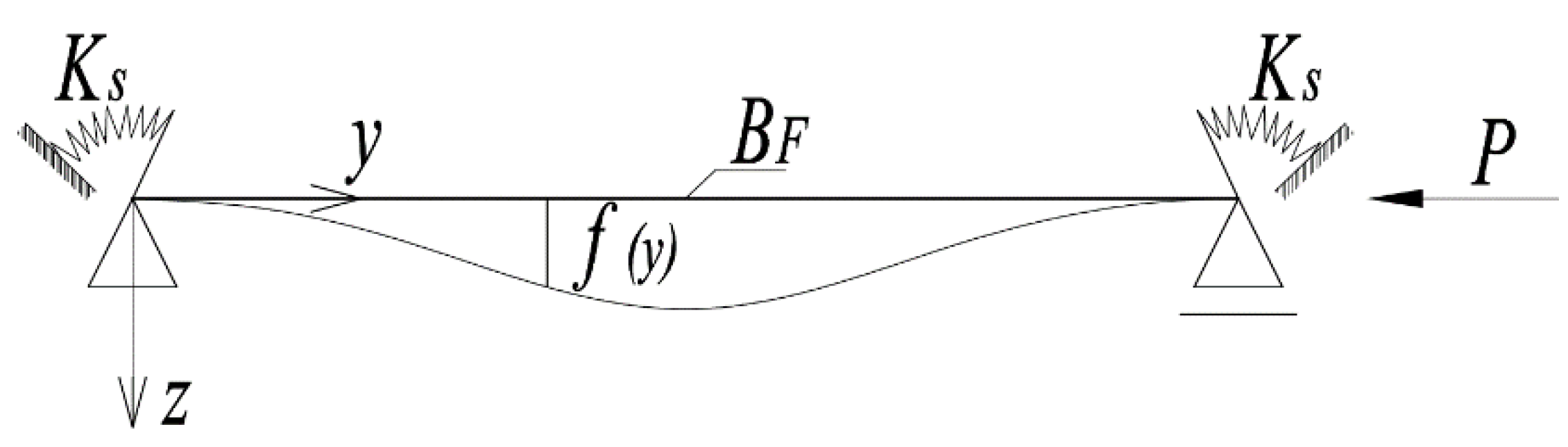
It should be expected that in practice, the best representation of the facing band deformation will be the application of the deformation as for a simply supported rod, with an additional elastic restriction of rotation (Figure 3). In this case, the solution depends, among other things, on the relationship between the facing stiffness (5) and the stiffness of the elastic support per unit length of the band (hereinafter designated as ).
Figure 3.
A rod with elastic rotational support on supports.
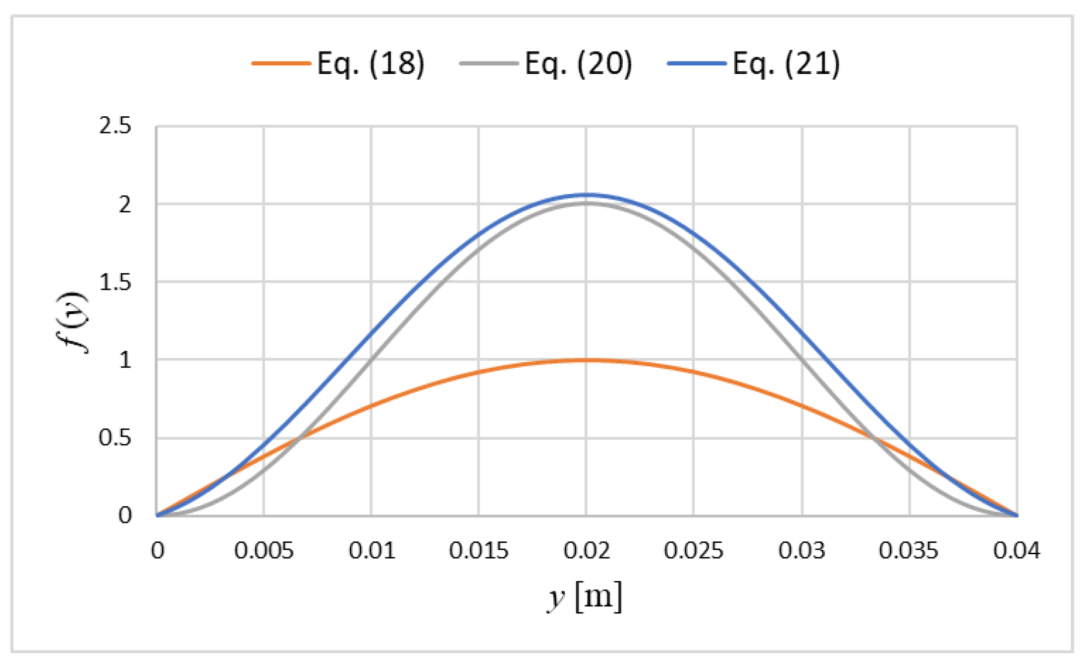
To find the deformations shown in Figure 4, for given values of , and , one should determine corresponding to buckling. Then, using any three independent boundary conditions, the following function is found:
Functions (18), (20), and (21) are illustrated in Figure 4.
Figure 4.
Examples of functions of deformation (18), (20), and (21).
4.2. Wrinkling Stress as a Function of Width
To maintain the generality of the considerations, the solution for the function (19), i.e., the function that takes into account the possibility of multiple half-waves of the sine wave, is presented below. Equations (11) and (16) then take the form:
The optimal and are best found numerically, and then substituted into (22) and the wrinkling stress determined from (17). For and the following data: kNm, MPa, MPa, Figure 5 illustrates the critical stress as a function of the facing band width . The graph corresponding to function (19) is described as ‘simply supported edges’. It is worth adding that the parameters assumed above correspond to typical values of manufactured sandwich panels.
Proceeding similarly as above, for the more general form of (20) , the load function
and the optimality conditions
are obtained. The solution in the form of critical stress as a function of the facing band width is shown in Figure 5 and marked as ‘fixed edges’.
Figure 5.
Wrinkling stress as a function of width .
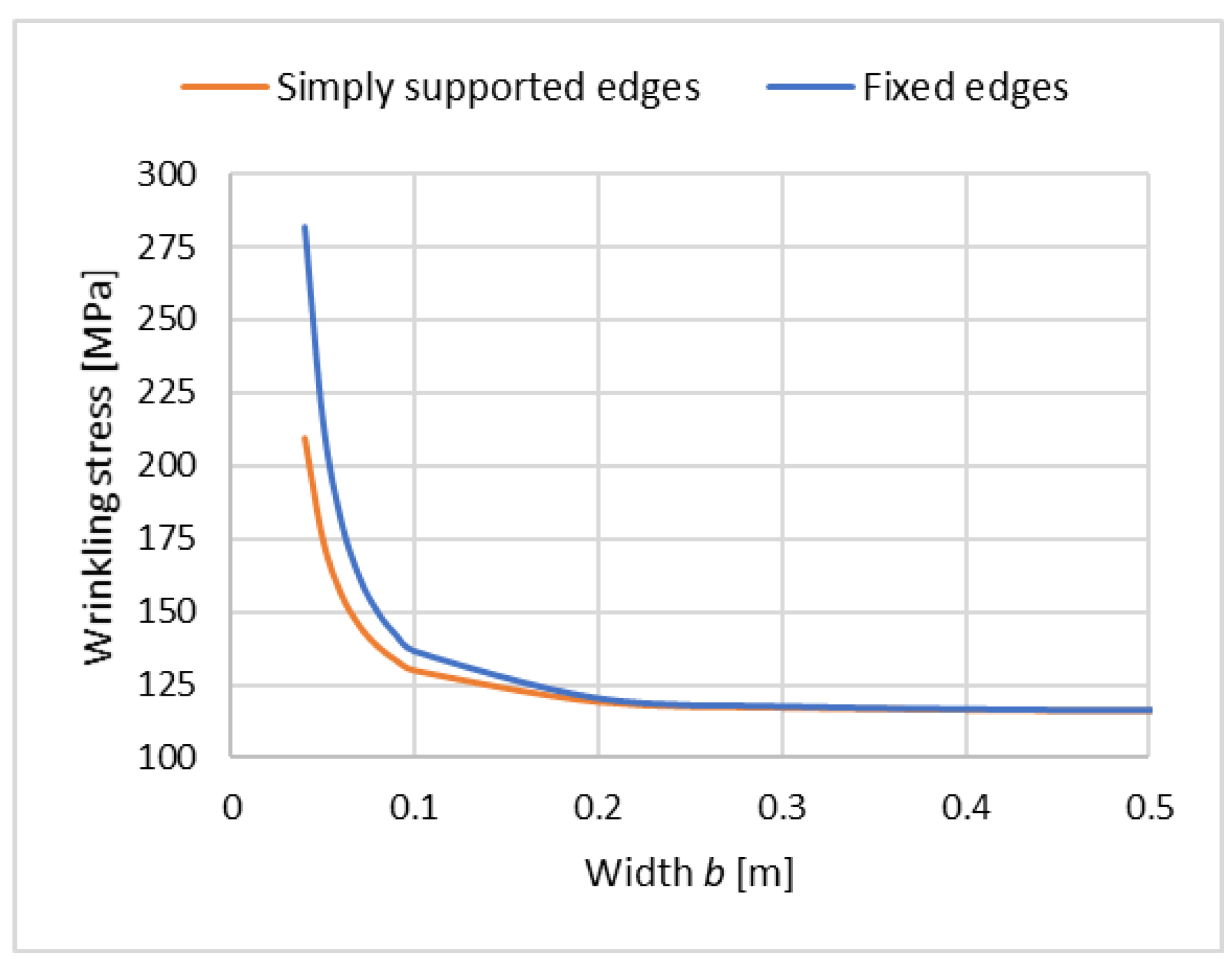
Several important conclusions can be drawn from the analysis of the results presented in Figure 5. First of all, it turns out that changing the band width in the range of up to 0.1 m has no significance for the critical stress. The load-bearing capacity of the band (and consequently also of the sandwich panel) increases only when the width of the band becomes smaller than 0.1 m, and this is basically independent of the way of supporting the edges of the band.
Comparison of the wrinkling stresses for simply-supported edges and fixed edges of the band shows that, of course, the stresses are higher for the fixed edges. However, more importantly, for the given material parameters and for the specified static scheme, the wrinkling stress has a particular, specific value. For m, with the simply supported edges of the band, the wrinkling stress is 209.38 MPa, and with the fixed edges, it is 281.71 MPa. For elastic restriction of rotation at the edges of the band, the stress value will be between these values. Therefore, sandwich panel manufacturers can obtain a higher wrinkling stress by slightly reducing the width of the band or modifying (improving) the material parameters. It is worth adding that the stress values obtained in the presented examples are consistent with the order of stress values obtained in experimental tests. In the case of good-quality sandwich panels, the wrinkling stress of the analyzed facing band reaches a value of approximately 280 MPa.
4.3. Parametric Analysis
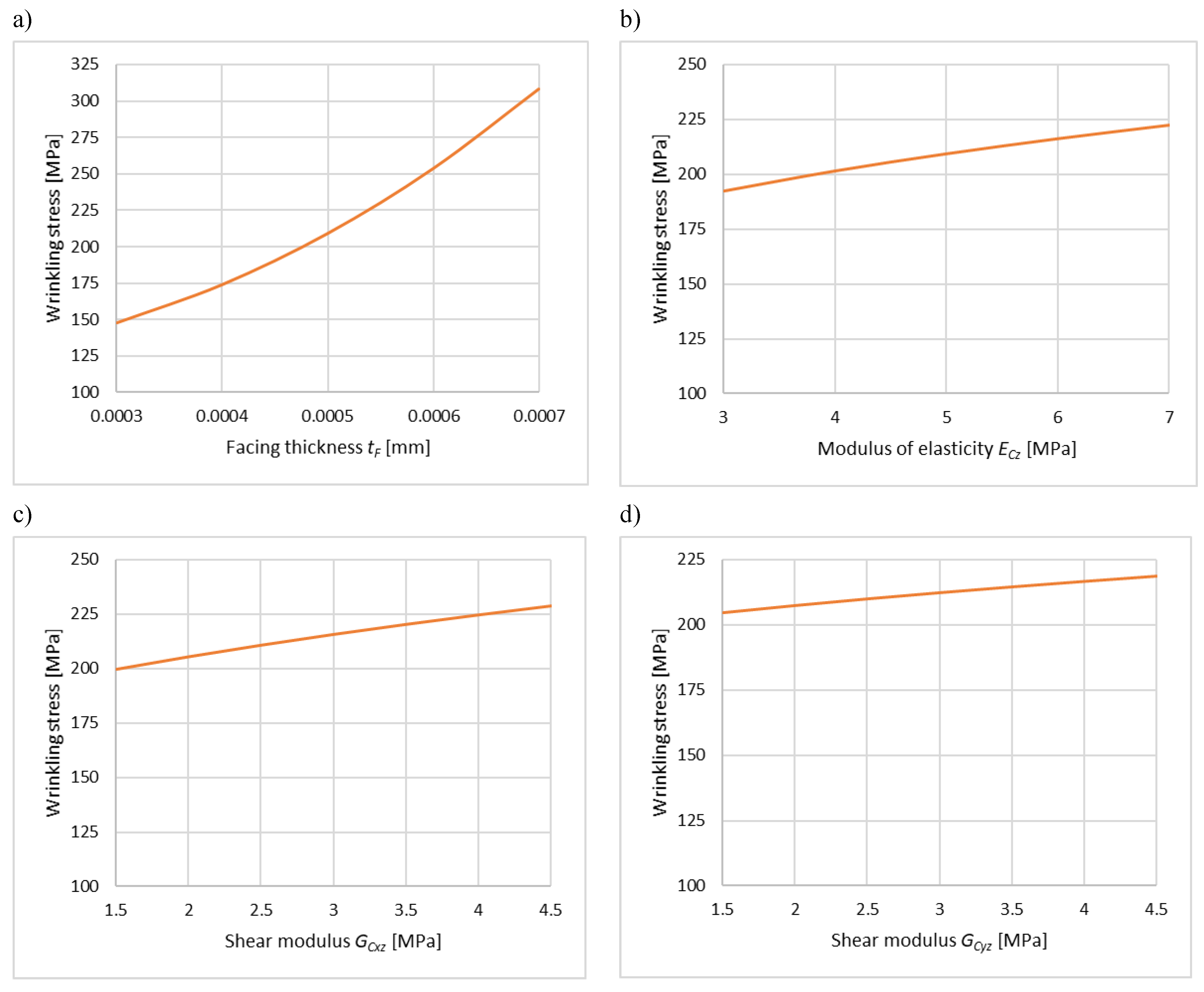
To provide a more comprehensive analysis of the obtained solution, the corresponding parametric analysis is presented below. Figure 6 presents the values of the wrinkling stress as a function of the variation of: the facing thickness in the range from 0.30 mm to 0.70 mm (Figure 6a), the modulus of elasticity of the core in the range from 3.0 MPa to 7.0 MPa (Figure 6b), and the shear moduli and in the range from 1.5 MPa to 4.5 MPa (Figure 6c and Figure 6d, respectively). These analyses were performed for a band width of m. For the presented parametric analyses, in the case of variation of one of the parameters, the remaining ones were set as given in Section 4.2.
Most of the observations made from Figure 6 are, of course, in line with expectations. The higher the core stiffness, the higher the wrinkling stresses. Wrinkling stresses are moderately sensitive to the change of , and modules. However, it is worth noting that the critical stresses clearly increase with the increase in the thickness of the facing (Figure 6a). Of course, the critical load must be greater because the thickness of the facing is greater; however, the significant increase in stress is somewhat surprising. All the more so because the standard [24] assumes an inverse relationship, i.e., when converting the wrinkling stress from a thinner to a thicker facing according to the standard procedures, the wrinkling stress decreases.
Figure 6.
Stress wrinkling the facing band as a function of variation of: a) facing thickness , b) modulus of elasticity of the core , c) shear modulus of the core , d) shear modulus of the core .
Figure 6.
Stress wrinkling the facing band as a function of variation of: a) facing thickness , b) modulus of elasticity of the core , c) shear modulus of the core , d) shear modulus of the core .
5. Conclusions
The problem of local instability (wrinkling) of the facing band of a sandwich panel was analyzed in the paper. The facing band rests on a shear-deformable core and can be treated as supported on its edges due to the deep profiling of the facing. Both the support of the band on the core and the support of the band edges stabilize the band deformations. In this paper, the case of uniaxial compression of the facing band, which is caused by typical mechanical actions, was considered.
In the first part of the paper, an energy approach was applied to the problem, which enabled the determination of the compressive load function of the facing band and the calculation of the optimality conditions leading to the calculation of the wrinkling stress. The solution was presented in a general form for an arbitrary function describing the deformation of the facing band.
In the next stage of considerations, the derived equations were used, and exemplary solutions for the basic forms of the deformation function were presented. The presented theoretical approach allowed to show that the significant increase in wrinkling stresses occurs for band width less than 0.10 m. In addition, values corresponding to different support conditions of the band were obtained, thanks to which the range of wrinkling stress obtained in practice was known. To the authors' knowledge, the presented results have not been previously obtained on the basis of theoretical considerations.
Based on the derived equations, an analysis of the wrinkling stress variation as a function of the change in the facing thickness and parameters describing the core stiffness was carried out. One observation is that the wrinkling stresses increase strongly with the increasing thickness of the facing. This relationship, although logical, is inconsistent with the current normative provisions concerning sandwich panels.
The considerations presented in the article explain the issue of the influence of the band width on wrinkling stress. The derived equations can be directly used when planning a change in the production program of sandwich panels. The presented analyses indicate both the real possibilities of improving the load-bearing capacity of sandwich panels and the limitations related to increasing this capacity.
Author Contributions
conceptualization, Z.P. and J.P.; methodology, Z.P. and J.P.; software, J.P. and Z.M.; validation Z.P. and D.C.; formal analysis, Z.P. and Z.M.; investigation, Z.P. and J.P.; resources, Z.P. and D.C.; data curation, J.P. and Z.M.; writing—original draft preparation, Z.P. and J.P.; writing—review and editing, Z.M. and D.C.; visualization, J.P. and D.C.; supervision, Z.P. and Z.M.; project administration, J.P. and D.C.; funding acquisition, Z.P. All authors have read and agreed to the published version of the manuscript.
Funding
The presented research was funded by the Ministry of Science and Higher Education in Poland as part of a grant for the Poznan University of Technology, projects No. 0213/SBAD/0122 and 0411/SBAD/0012.
Institutional Review Board Statement
Not applicable.
Informed Consent Statement
Not applicable.
Data Availability Statement
The data presented in this study are available on request from the corresponding author.
Conflicts of Interest
The authors declare no conflict of interest. The funders had no role in the design of the study, in the collection, analysis, or interpretation of data, in the writing of the manuscript, or in the decision to publish the results.
References
- Hoff, N.J.; Mautner, S.E. Buckling of Sandwich Type Panels. Journal of the Aeronautical Sciences 1945, 12, 285–297. [Google Scholar] [CrossRef]
- Plantema, F.J. Sandwich Construction; the bending and buckling of sandwich beams, plates and shells; John Wiley & Sons, Inc.: New York, USA, 1966. [Google Scholar]
- Allen, H.G. Analysis and Design of Structural Sandwich Panels; Pergamon Press: Oxford, UK, 1969. [Google Scholar]
- Birman, V.; Bert, C.W. Wrinkling of composite-facing sandwich panels under biaxial loading. Journal of Sandwich Structures & Materials 2004, 6, 217–237. [Google Scholar] [CrossRef]
- Koissin, V.; Shipsha, A.; Skvortsov, V. Wrinkling in sandwich panels – an analytical approach. Journal of Sandwich Structures & Materials 2011, 13, 705–730. [Google Scholar] [CrossRef]
- Fagerberg, L; Zenkert, D. Effects of anisotropy and multiaxial loading on the wrinkling of sandwich panels. Journal of Sandwich Structures & Materials 2005, 7, 177–194. [Google Scholar] [CrossRef]
- Birman, V.; Jeffrey, L. Wrinkling in sandwich panels with bi-modular core. Zeitschrift für Angewandte Mathematik und Mechanik 2020, 100, 1–13. [Google Scholar] [CrossRef]
- Hohe, J.; Librescu, L. Recent results on the effect of the transverse core compressibility on the static and dynamic response of sandwich structures. Composites. Part B: Engineering 2008, 39, 108–119. [Google Scholar] [CrossRef]
- Birman, V. Dynamic wrinkling in sandwich beams. Composites. Part B: Engineering 2004, 35, 665–672. [Google Scholar] [CrossRef]
- Murčinková, Z.; Živčák, J.; Zajac, J. Experimental study of parameters influencing the damping of particulate, fibre-reinforced, hybrid, and sandwich composites. International Journal of Materials Research 2020, 111, 688–697. [Google Scholar] [CrossRef]
- Phan, C.N.; Bailey, N.W.; Kardomateas, G.A.; Battley, M. A. Wrinkling of sandwich wide panels/beams based on the extended high-order sandwich panel theory: formulation, comparison with elasticity and experiments. Archive of Applied Mechanics 2012, 82, 1585–1599. [Google Scholar] [CrossRef]
- Birman, V.; Vo, N. Wrinkling in sandwich structures with a functionally graded core. Journal of Applied Mechanics 2017, 84, 021002. [Google Scholar] [CrossRef]
- Su, W.; Liu, S. New method for predicting the wrinkling stress in sandwich panels. Archive of Applied Mechanics 2025, 95. [Google Scholar] [CrossRef]
- Ginot, M.; Bouvet, C.; Castanié, B.; Serra, J.; Mahuet, N. Local buckling on large sandwich panels used in light aviation: experimental setup and failure scenarios. Composite Structures 2023, 304, 116439. [Google Scholar] [CrossRef]
- Ren, X.; Zhang, S; Wu, Z. A strategy resisting wrinkling of sandwich structures reinforced using functionally-graded carbon nanotubes. Chinese Journal of Aeronautics 2023, 36, 243–255. [Google Scholar] [CrossRef]
- Gdoutos, E.E.; Daniel, I.M.; Wang, K.A. Compression facing wrinkling of composite sandwich structures. Mechanics of Materials 2003, 35, 511–522. [Google Scholar] [CrossRef]
- Steineck, S.; Lange, J. Material Behavior of PIR Rigid Foam in Sandwich Panels: Studies beyond Construction Industry Standard. Materials 2024, 17, 418. [Google Scholar] [CrossRef]
- Pradhan, E.M.; Lange, J. Warping Torsion in Sandwich Panels: Analyzing the Structural Behavior through Experimental and Numerical Studies. Materials 2024, 17, 460. [Google Scholar] [CrossRef]
- Indreș, A.I.; Constantinescu, D.M.; Mocian, O.A. Bending behaviour of 3D printed sandwich beams with different core topologies. Material Design & Processing Communications 2021, 3, e252. [Google Scholar] [CrossRef]
- Atalay Kalsen, T.S.; Karadağ, H.B.; Eker, Y.R. The Out-Of-Plane Compression Behavior of In Situ Ethylene Vinyl Acetate (EVA)-Foam-Filled Aluminum Honeycomb Sandwich Structures. Materials 2023, 16, 5350. [Google Scholar] [CrossRef]
- Hassinen, P.; Misiek, T. Einfluss von Inhomogenitäten im Kernwerkstoff von Sandwichelementen auf die Tragfähigkeit. Stahlbau 2012, 81, 935–943. [Google Scholar] [CrossRef]
- Pozorski, Z.; Pozorska, J. Influence of the Heterogeneity of the Core Material on the Local Instability of a Sandwich Panel. Materials 2022, 15, 6687. [Google Scholar] [CrossRef]
- Pozorski, Z.; Pozorska, J.; Kreja, I.; Smakosz, Ł. On Wrinkling in Sandwich Panels with an Orthotropic Core. Materials 2021, 14, 5043. [Google Scholar] [CrossRef]
- EN 14509:2013; Self-supporting double skin metal faced insulating panels – Factory made products – Specifications. European Committee for Standardization: Brussels, 2013.
Disclaimer/Publisher’s Note: The statements, opinions and data contained in all publications are solely those of the individual author(s) and contributor(s) and not of MDPI and/or the editor(s). MDPI and/or the editor(s) disclaim responsibility for any injury to people or property resulting from any ideas, methods, instructions or products referred to in the content. |
© 2025 by the authors. Licensee MDPI, Basel, Switzerland. This article is an open access article distributed under the terms and conditions of the Creative Commons Attribution (CC BY) license (https://creativecommons.org/licenses/by/4.0/).
Copyright: This open access article is published under a Creative Commons CC BY 4.0 license, which permit the free download, distribution, and reuse, provided that the author and preprint are cited in any reuse.


