Submitted:
07 October 2025
Posted:
08 October 2025
You are already at the latest version
Abstract
In this paper, we focus on the performance of reverse electrodialysis stacks and suggest new designs to improve power density and fuel efficiency by using fractal concepts. Two methods are discussed, namely membrane profiling and the assembly of stacks from a number of smaller stacks.
Keywords:
salinity gradient energy
; renewable energy
; reverse electrodialysis
; electrodialysis
; fractal design
; stack design
1. Introduction
There are a handful of techniques for converting the Gibbs free energy contained in salinity gradients into usable electrical energy. The most important are pressure-retarded osmosis (PRO) and reverse electrodialysis (RED) [1]. PRO is based on the selective permeability of water through membranes, while RED uses membranes capable of transporting ions. In this paper, we limit ourselves to RED and also highlight the possibilities for electrodialysis (ED). RED is performed in stacks consisting of alternating anion exchange membranes (AEMs) and cation exchange membranes (CEMs). Membranes are separated from each other by porous structures known as spacers, which provide access to the feedwaters, i.e., a low-concentration solution (LC) and a high-concentration solution (HC). The spacers between the membranes have a dual purpose: they supply the feedwater and ensure mixing within the feedwater compartments. The concept of RED is shown in Figure 1a. The rinse solution contains the salts FeCl2 and FeCl3 dissolved in a NaCl bulk solution. The redox couple Fe2+/Fe3+ ensures that the ion current in the stack is converted into an electrical current at the electrodes.
Energy can also be harvested from salinity gradients if only one type of ion exchange membrane (IEM) is available. The concept was described by Clampitt and Kiviat in 1976 [2] and is shown in Figure 1b. In principle, such cells can be stacked as proposed in Figure 1c. Because the Ag/AgCl electrodes are active parts of the process, the process should be reversed by switching the feedwater supplies after some time. It is clear that silver electrodes are costly, pose a threat to the environment and also present challenges to both performance and long-term stability. Instead the combination of inert electrodes with a redox couple, capacitive electrodes can also be used as shown in Figure 1d. When the activated carbon of these electrodes becomes saturated after a while, the current direction must be periodically reversed, which is accomplished by switching the feedwaters [3]. Capacitive electrodes can also be used if only one type of IEM is available (Figure 1e). Such a system was been described by Wu et al. [4]. In theory, such a system can also be stacked (Figure 1f); however, this has not been reported anywhere in the scientific literature.
Figure 2 shows the various flow options through the compartments [6]. For co- and counterflow, supply through channels within the stack perpendicular to the membranes is necessary, as is the case for the point-to-point cross-flow stack. A new feature is the cross-flow stack with inflow from the sides, as developed by REDstack B.V. (Heerenveen, the Netherlands). This stack is marketed in a round housing [7]. The stacks described in the literature for RED are all plate-and-frame types. However, spiral-wound modules have been developed for ED [8] and for electro-deionization (EDI) [9], but have not yet been applied to RED until now.
The two most important parameters that describe the behavior of a RED stack include the generated power density and the efficiency of the process. The net power density (Pdnet) is the produced electrical power (Pel ) minus the hydrodynamical losses (Phydr) per square meter active of membrane (A) (both AEM and CEM).
The net efficiency is achieved from the net power Pnet and the theoretical maximum energy of the reversible mixing process (Pth).
Especially with river water and seawater as feedwaters, it is more convenient to use, instead of the efficiency, the net river water yield Znet: the net produced energy per m3 river water:
In optimizations where both power density and yield play a role, the net response product RPZ is a useful parameter:
Sometimes, a power density is assigned to a single membrane. This Pdmem can be approximated by measuring the membrane areal resistance Ra and the membrane voltage E, also known as the open circuit voltage (OCV).
Here isc stands for the short-circuit current, E1/2 for half of E and i1/2 for half of Isc. Measuring isc can sometimes be problematic. In practice, the OCV is often measured first and then the measuring circuit is loaded in such a way that the membrane potential drops to half. At that time, the current is i1/2. Especially, measurements on small membrane areas can be confusing. Derkenne et al. found a strong negative relation between the membrane area and power density [10]. Probably this effect also plays a role in measurements on the extremely small openings in micro- and nano-pores.
2. Higher Power Density and Efficiency
Extensive research into power density has been conducted Vermaas et al. with feedwaters containing NaCl solutions of 1 and 30 g/L. Applying 100 μm spacers and 50 μm membranes, they harvested 1.2 Watts per m2 membrane. (Pdel=2.2 W/m2 and Pdhydr=1.0 W/m2) with an efficiency of about 30% [11]. To put this into perspective: A cell pair has a thickness of 300 μm. A cube-shaped stack of 10×10×10 cm3 (about 1 kg excluding the housing etc.) can contain 3.33 m2 of these cell pairs or 6.67 m2 membranes and delivers with Pdnet=1.2 W/m2 a net power of 8 Watts. For comparison: Tour de France cyclist Pogačar produced a power of 6.9 Watts per kg body weight for 15 minutes toward the end of a 5-hour long Tour de France stage [12]. The question is how we can achieve better performance with a RED stack. Solutions can be found in optimizing the stack design, improving the membranes used, and developing new feed channel designs with profiled membranes. In this chapter, we will review several options as described in the literature.
2.1. Stack Optimization
An important point with the classic construction of RED and ED stacks according to the plate-and-frame method is that the ions that only diffuse through the membranes at the end of a flow channel must have completed a journey through the entire compartment along with the solvent at the price of substantial hydrodynamic losses. It is therefore clear that the scale has a negative influence on performance. This effect was investigated by Veerman et al. [13]. They modeled a stack in co-flow operation that was successively equipped with four different combinations of spacers and membranes. For the spacers, ideal spacers were used (i.e., spacerless compartments) and real woven spacers; for the membranes ideal membranes (without electrical resistance and 100% permselective) and real commercial membranes (Qianqiu) were taken. Maximum net power density (Pdnet) was found by adjusting the thickness of both (HC and LC) flow channels and both flow rates. Table 1 shows the net power density for the four cases for stacks with feedwater channel lengths of 0.01 m, 0.1 m, and 1 m. It is clear that the scale negatively impacts the RED performance.
Scale also has a large influence on the required thickness of the flow channels. Table 2 shows the results of the fit procedure for stacks with flow channels of 0.01 m, 0.1 m and 1 m. The first three data columns are achieved when the net power density (Pdnet) is maximized and the last three columns are the result of maximizing the response product (RPZ) [14]. Table 2 shows that the response product is more suitable than the net power density as an optimization parameter. The river water yield then remains more or less the same with a changing feedwater length. Furthermore, it appears that much thinner spacers can be used if shorter feedwater channels are applied.
Going from a flow channel of 1 to 0.1 meter while maintaining the same membrane width, the individual membrane surface area decreases by a factor of 10. To achieve the same total membrane surface area, the stack must therefore have 10 times more cell pairs. The membranes remain the same thickness, but the spacers become approximately 3 times thinner, resulting in a stack height increase of approximately 5 times.
Although these considerations are derived for a co-flow fed RED stack, they are also indicative for counter- and cross-flow stacks. For modern cross-flow stacks (with side-flow feed, such as the stacks from REDstack bv, for example), the lengths of the seawater and river water channels are independent. Because the seawater compartments can be thicker due to the high conductivity of seawater, they can also be longer than those of the river water. In practice, the question arises whether an excess of seawater is even desirable because the stack model does not account for the effort required to pre-purify and transport the seawater. In practice, this may even mean that an under sizing (ΦS/ΦR<1) is more advantageous. A final consideration is that extreme miniaturization will defeat the purpose because part of the membrane surface is inactive due to the seals present. Asymmetric stacks also have the disadvantage that capacitive electrodes cannot be used because the feedwater switch does not result in the desired flow reversal.
2.2. Classical Ion Exchange Membranes
Ion exchange membranes (IEMs) were originally based on organic polymers. Homogeneous IEMs contain chemically bonded anions such as ~NR3+ in an AEM or cations such as ~SO3- in a CEM; in contrast, heterogeneous IEMs contain organic acids or bases mixed with a neutral polymer matrix. Abidin et al. summarized the properties of a number of commercial ion exchange membranes [15]. Figure 3 shows the results of the membrane power density Pdmem. Concerning the CEMs, there was one membrane with excellent properties: Nafion-117 with Pdmem = 4.2 W/m2. The average value for the CEMs without this Nafion-117 was 1.3 W/m2 for a range between 0.4 and 2.3 W/m2. The average of the AEMs was 0.9 W/m2 for a range between 0.3 and 1.5 W/m2.
2.3. New Membranes
In 2010 Kim et al. published their experiments with ion-selective nanochannels etched in a silica chip [16]. They achieved an electrical power density of 7.7 W/m2 with a concentration ratio of 1000. This power density was much higher than was possible with classical membranes. This result triggered researchers all over the world to improve this value with nanochannels in other materials. In 2013, Siria et al. published a paper describing the ion conductivity in a single boron nitride nanotube [17]. A huge power density was predicted based on the measured i–E curve. A value of 6000 W/m2 was estimated with solutions with high pH (pH 9.5) and a high concentration ratio (CHC/CLC) of 1000. However, for conditions more similar to Blue Energy conditions (seawater with river water), i.e., pH = 5.5 and a concentration ratio of 30, the power density was only 20 W/m2. A few years later, Feng et al. published a paper in which an extraordinary power density of 106 W/m2 was reported [18]. Measurements were performed on a single nanopore in a MoS2 substrate.
Since then, there has been a great search for new materials for IEMs. In particular, two-dimensional materials are good candidates. Examples are graphene, hexagonal boron nitride, transition metal dichaicogenides, mono-elemental Xenes, and covalent organic frameworks [19,20]. For the year 2024, we found the results listed in Table 3. It is remarkable that there are only two AEMs among them, both with good but not excessive properties.
The performance of a classical RED stack according to Figure 1a is greatly influenced by the less-performing membrane. Combination of an extremely good CEM with a normal AEM will therefore add little to the overall performance. In contrast, an equipment that consists of a single membrane (such as in Figure 1b and c will, however, experience the limitations that have been outlined in Table 1 even when it concerns an excellent membrane. For a stack of 10×10 cm2, a power density of 19 W/m2 is a theoretical limit that is not to be crossed. However, there is another limitation and that is the performance of the electrode system. In all reported tests of nanopores, relatively large Ag/AgCl electrodes were used together with a single micro-pore or with a very small membrane. In these cases, the power density was not limited by the electrode system. However, for practical applications, the electrode area should be equal to the individual membrane area as seen in Figure 1b and c. This implies that the resistance of the electrode system (capacitive or Ag/AgCl) plays the same role in performance as the membranes. Little is currently known about the behavior of these electrode systems at high current densities and therefore, the application of CEM-only will still face many challenges. So some skepticism about highly claimed power densities in nano power generation (NPG) is desirable. Wang et al. even arrive at shockingly low performances of this technique, if operated on a larger scale [40] The authors estimate a power density of less than 0.1 W/m2 in combination with a net specific extractable energy (SEEnet) of less than 0.025 kWh/m3.
2.4. Profiled Membranes
The task of spacers in RED and ED is to keep the membranes at a distance from each other and thus create a fluid channel. Moreover, the spacer also serves as a mixing promoter. However, the better the stirring function, the greater the pressure losses. Spacers are in most cases woven or extruded structures that are not ion-conductive, which results in an increased electrical resistance by the so-called shadow effect. Instead of spacers, feed channels can also be created by applying profiles in or on the membranes. Profiled membranes does not have this shadow disadvantage and also open up a wide range of possible shapes for the flow channels. Profiled membranes are also known as micro-structured, corrugated, or patterned membranes. Many structures are implemented in practice, for example with chevrons [41], ridges [42] pillars [43], waves [44] or other objects [45,46,47]. The aim is always to combine a low electrical resistance with a low hydrodynamic resistance and a high power density. The function as a mixing promoter must also be taken into account with the aim of minimizing the concentration polarization. Computational fluid dynamics (CFD) shows the advantages of profiling [48,49,50,51].
Nikoneno et al. [52] launched the technique of membrane profiling in 2008 for electrodialysis and more or less at the same time a publication by Larchet et al. appeared in which this application was compared with other methods of improving the flow channels [53]. Membranes were profiled by hot pressing the heterogeneous commercial MA-40 AEM. Compared to woven or extruded spacers, profiled membranes have a number of advantages. Vermaas et al. introduced profiled membranes in the RED technology [42]. They used the commercial heterogeneous membranes Ralex CMH and AMH (Mega a.s. Czech Republic). The main conclusion was that the hydrodynamic resistance decreased significantly due to the profiling. This is an important result with a view to future increases in scale. Also with hot pressing, using the same membranes, Pawlowski et al. succeeded in producing chevron-profiled as well as pillar-profiled membranes for RED [43]. It was found that the stack with chevrons delivered the highest power density which was attributed to a better mixing in the compartments.
Initially, membrane profiling was only performed by hot pressing but in 2016 Seo et al. published their experiments with 3D-printed anion exchange membranes by means of photoinitiated free radical polymerization followed by quaternization [54]. The membrane produced in this way was found to have a lower ionic resistance than unprofiled membranes with the same effective thickness. A third method to pattern membranes is casting. Güler et al. prepared, in this way, a CEM and an AEM for use in RED [44], whereas Liu et al. used membrane casting for improving their microbial reverse-electrodialysis cells [55]. Gurreri et al. introduced screen printing as a method to apply profiling [56]. By applying a cross-linked resin to an existing commercial membrane, two different types of profiling were applied in this way, namely overlapped crossed filament (OCF) and pillars.
3. Fractal Design
A fractal system is characterized by a structure that is repeated in smaller formats inside that structure. This multiplication can be repeated a limited number of times in physical systems and even infinitely times in mathematical models [57]. Fractal systems for mass transfer are common in animals and plants. Examples include the human lungs, which are fed via the trachea that branches into the bronchi and the bronchioles and in the aveoli where the gas exchange occurs. Blood vessels in the body and in the placenta are also examples of fractal systems as well as the roots and the branches of trees. It is therefore not surprising that fractal systems also are applied in chemical engineering [58].
3.1. Fractal Profiled Membranes
The first step in the direction of fractal systems in RED technology was taken by Veerman et al. [13,59]. They designed a stack in which the feed channels are created by applying profiles in a membrane. Figure 4 shows the concept.

Table 4.
Properties of Ralex membranes.
| Ralex membrane |
IEC | Perm-selectivity | Rarea | Swelling degree | Thickness dry |
Thickness wet |
| meq/g dry | % | Ω∙cm2 | % | μm | μm | |
| AMH-PES | 1.97 | 94.7 | 7.66 | 56 | 764 | |
| CMH-PES | 2.34 | 89.3 | 11.33 | 31 | 450 | 714 |
The conductivity of seawater is much higher than that of river water, and the extent to which this system is useful for both feedwaters is questionable. In addition to the inlet concentrations, the outlet concentrations must also be considered. Assuming inlet concentrations of 1 and 30 g/L and a salt transport of 4 g/L, this results in outlet concentrations of 5 and 26 g/L.
Figure 5 shows the areal resistances at three locations through the membrane: through the entire unprofiled membrane (A), through the thin membrane with the deep feed channel (B), and through the slightly compressed membrane with a thin water layer (C). For river water, route C appears to be more advantageous, but for seawater, this advantage disappears entirely. The conclusion is therefore that a stack can be equipped with these fractal membranes for the river water compartment, but for the seawater compartment it is more practical to use either a traditional woven spacer or one of the profiled membranes as described in Section 2.4.
Based on Figure 4, the question is how this design can be applied to a membrane in a cross-flow stack. Figure 6d shows a design with very deep feed channels (colored orange) and shallow channels in the reactor part (blue). The feed channels are adapted to the local flow rate, resulting in a wide inlet as the channel gradually narrows; the reverse is true for the outlet channels. Figure 6b is a slight variation on this. It may be necessary to add a few support pillars to the feed channels.
This idea is further elaborated in Figure 7. A Ralex CEM (CHM-PES) measuring 15.5×5.5 cm2 was used, with one segment shown. The membrane accommodates 10 of these segments. Assuming a wetted thickness of 0.8 mm, feed channels were pressed into the membrane to a depth of 0.6 mm, while the reactor section has a depth of 0.1 mm. The calculations show that hydraulic losses are very low.
3.2. Fractal Stacks
Instead of applying the fractal concept at membrane level, a more obvious option is to apply it to the entire stack. Figure 8a shows such a fractal stack, composed of 16 classic RED stacks. For clarity, the feeder channels have been omitted. These are visible in the top view in Figure 8b. These channels do take up a large part of the space, and Figure 8c shows that the feeder channels can be made considerably thinner.
Furthermore, the compartments for seawater can be thicker and longer than those for river water because the conductivity is considerably higher than that of river water. The flow rates for river water and seawater can also differ in an optimized design. Figure 8d shows that these asymmetric stacks can be stacked in the same way.
4. Conclusions and Outlook
Many processes in chemical engineering are most efficient at large scales, while others are even more efficient at small scales. RED is an example of the latter. Fractal designs open up new possibilities for generating large power outputs while maintaining high efficiency. A challenge here is integrating two fluid flows with an electrical circuit. Solutions can be explored at both the membrane and stack levels. Such designs can also be beneficial for related technologies, such as conventional electrodialysis (ED).
Funding
This research received no external funding.
Data Availability Statement
The original contributions presented in the study are included in the article, further inquiries can be directed to the corresponding author.
Acknowledgments
This work was facilitated by REDstack BV in The Netherlands. REDstack BV aims to develop and market RED and the ED technology. The author would like to thank his former colleagues from the REDstack company for fruitful discussions.
Conflicts of Interest
Author J.V. was formerly employed by REDstack bv. REDstack bv had no role in the design of the study; in the collection, analyses, or interpretation of data; in the writing of the manuscript, or in the decision to publish the results.
Abbreviations
| AEM | anion exchange membrane |
| CEM | cation exchange membrane |
| CFD | computer fluid dynamics |
| cRED | capacitive RED |
| ED | electrodialysis |
| HC | high concentration feedwater |
| IEM | ion exchange membrane |
| LC | low concentration feedwater |
| OCF | overlapped cross filaments |
| RED | reverse electrodialysis |
| SEE | specific extractable energy |
| NPG | nanopore power generation |
References
- Veerman, J. Harvesting salinity gradient energy by diffusion of Ions, liquid water, and water vapor. Processes 2025, 13, 554. [Google Scholar] [CrossRef]
- Clampitt, B.H.; Kiviat, F.E. Energy recovery from saline water by means of electrochemical cells. Science 1976, 194, 719–720. [Google Scholar] [CrossRef]
- Vermaas, D.A.; Bajracharya, S.; Sales, B.B.; Saakes, M.M. Clean energy generation using capacitive electrodes in reverse electrodialysis. Energy & Environmental Science 2013, 6, 643–651. [Google Scholar] [CrossRef]
- Wu, N.; Levant, M.; Brahmi, Y.; Tregouet, C.; Colin, A. Blue energy harvesting and divalent ions: Capacitive reverse electrodialysis cell with a single membrane opens a gateway to new application. Research Square 2024. [Google Scholar] [CrossRef]
- Veerman, J.; Kunteng, D. Inorganic pseudo ion exchange membranes—Concepts and preliminary experiments. Applied Sciences 2018, 8, 2142. [Google Scholar] [CrossRef]
- Veerman, J. Reverse electrodialysis: co-and counterflow optimization of multistage configurations for maximum energy efficiency. Membranes 2020, 10, 206. [Google Scholar] [CrossRef]
- Veerman, J.; Hack, P.; Siebers, R. Blue energy from salinity gradients. The Journal of Ocean Technology 2023, 18, 26–36. [Google Scholar]
- Winter, A.G.; Wright, N.C. Spiral-wound electrodialysis module. Patent UA2019/0111393A1 (2019).
- Dow. Omexell, Spiral wound electrodeionization. Available online: https://www.lenntech.com/Data-sheets/DOW%20-EDI-210-L.pdf (accessed on 5 August 2025).
- Derkenne, T.; Colin, A.; Tregouet, C. Macroscopic access resistances hinders the measurement of ion-exchange-membrane performances for electrodialysis processes. ACS Applied Energy Materials 2024, 7, 6621–6629. [Google Scholar] [CrossRef]
- Vermaas, D.A.; Saakes, M.; Nijmeijer, K. Doubled power density from salinity gradients at reduced intermembrane distance. Environmental Science & Technology 2011, 45, 7089–7095. [Google Scholar] [CrossRef]
- Kaloc, J. Power numbers in grand tours—Vingegaard and Pogačar breaking records. Available online: https://www.welovecycling.com/wide/2023/08/30/ (accessed on 29 May 2025).
- Veerman, J.; Saakes, M.; Metz, S.J.; Harmsen, G.J. Reverse electrodialysis: A validated process model for design and optimization. Chemical Engineering Journal 2011, 166, 256–268. [Google Scholar] [CrossRef]
- Veerman, J. Reverse Electrodialysis—design and optimization by modeling and experimentation. Doctoral thesis University of Groningen (2010); https://pure.rug.nl/ws/portalfiles/portal/2625515/13complete.pdf.
- Abidin, M.N.Z.; Nasef, M.M.; Veerman, J. Towards the development of new generation of ion exchange membranes for reverse electrodialysis: A review. Desalination 2022, 537, 115854. [Google Scholar] [CrossRef]
- Kim, D.-K.K.; Duan, C.; Chen, Y.-F.F.; Majumdar, A. Power generation from concentration gradient by reverse electrodialysis in ion-selective nanochannels. Microfluidics and Nanofluidics 2010, 9, 1215–1224. [Google Scholar] [CrossRef]
- Siria, A.; Poncharal, P.; Biance, A.-L.; Fulcrand, R.; Blase, X.; Purcell, S.T.; Bocquet, L. Giant osmotic energy conversion measured in a single transmembrane boron nitride nanotube. Nature 2013, 494, 455–458. [Google Scholar] [CrossRef]
- Feng, J.; Graf, M.; Liu, K.; Ovchinnikov, D.; Dumcenco, D.; Heiranian, M.; Nandigana, V.; Aluru, N.R.; Kis, A.; Radenovic, A. Single-layer MoS2 nanopores as nanopower generators. Nature 2016, 536, 197–200. [Google Scholar] [CrossRef] [PubMed]
- Manikandan, D.; Karishma, S.; Kumar, M.; Nayak, P.K. Salinity gradient induced blue energy generation using two-dimensional membranes. npj 2D Materials and Applications 2024, 8, 47. [Google Scholar] [CrossRef]
- Fan, F.R.; Wu, W. Emerging devices based on two-dimensional monolayer materials for energy harvesting. AAAS Research 2019, 2019, 7367828. [Google Scholar] [CrossRef]
- Liu, X.; Li, X.; Chu, X.; Zhang, B.; Zhang, J.; Hambsch, M.; Mannsfeld, S.C.; Borrelli, M.; Löffler, M.; Pohl, D.; Liu, Y. Giant blue energy harvesting in two-dimensional polymer membranes with spatially aligned charges. Advanced Materials 2024, 36, 2310791. [Google Scholar] [CrossRef] [PubMed]
- Mai, V.-P.; Fauziah, A.R.; Gu, C.-R.; Yang, Z.-J.; Wu, K.C.-W.; Yeh, L.-H.; Yang, R.-J. Two-dimensional metal–organic framework nanocomposite membranes with shortened ion pathways for enhanced salinity gradient power harvesting. Chemical Engineering Journal 2024, 484, 149649. [Google Scholar] [CrossRef]
- Liu, J.; Wang, L.M.J.; Feng, Z.; Li, X.; Cao, M. Highly conductive anti-fouling anion exchange membranes for power generation by reverse electrodialysis. Journal of Power Sources 2024, 598, 234176. [Google Scholar] [CrossRef]
- Guo, Y.; Sun, X.; Ding, S.; Lu, J.; Wang, H.; Zhu, Y.; Jiang, L. Charge-gradient sulfonated poly (ether ether ketone) membrane with enhanced ion selectivity for osmotic energy conversion. ACS Nano 2024, 18, 7161–7169. [Google Scholar] [CrossRef]
- Li, J.; Li, C.; Dou, H.; Zhang, X.; Dai, Y.; Xia, F. PET-hydrogel heterogeneous membranes that eliminate concentration polarization for salinity gradient power generation. Journal of Membrane Science 2024, 698, 122644. [Google Scholar] [CrossRef]
- Qin, S.; Yang, G.; Wang, S.; Ma, Y.; Wang, Z.; Wang, L.; Liu, D.; Lei, W. Tunable surface charge of layered double hydroxide membranes enabling osmotic energy harvesting from anion transport. Small 2024, 20, 2400850. [Google Scholar] [CrossRef]
- Chen, C.; Meng, L.; Cao, L.; Zhang, D.; An, S.; Liu, L.; Wang, J.; Li, G.; Pan, T.; Shen, J.; Chen, Z. Phase engineering of zirconium MOFs enables efficient osmotic energy conversion: structural evolution unveiled by direct imaging. Journal of the American Chemical Society 2024, 146, 11855–11865. [Google Scholar] [CrossRef]
- Awati, A.; Yang, R.; Shi, T.; Zhou, S.; Zhang, X.; Zeng, H.; Lv, Y.; Liang, K.; Xie, L.; Zhu, D.; Liu, M. Interfacial super-assembly of vacancy engineered ultrathin-nanosheets toward nanochannels for smart ion transport and salinity gradient power conversion. Angewandte Chemie International Edition 2024, 63, 202407491. [Google Scholar] [CrossRef]
- Cao, L.; Wu, H. Dual-network fiber-hydrogel membrane for osmotic energy harvesting. Frontiers in Chemistry 2024, 12, 1401854. [Google Scholar] [CrossRef]
- Ren, Z.; Zhang, Q.; Yin, J.; Jia, P.; Lu, W.; Yao, Q.; Deng, M.; Gao, Y.; Liu, N. Enhancing osmotic energy harvesting through supramolecular design of oxygen-functionalized MXene with biomimetic ion channel. Advanced Functional Materials 2024, 34, 2404410. [Google Scholar] [CrossRef]
- Wang, S.; Shan, Z.; Ahmad, M.; Li, Z.; Sun, Z. Robust holey graphene oxide/cellulose nanofiber composites for sustainable and efficient osmotic energy conversion. ACS Applied Nano Materials 2024, 7, 4265–14274. [Google Scholar] [CrossRef]
- Wu, C.; Wang, J.; Wu, R.; Zeng, H.; Chen, X.; Yao, C.; Zhou, J.; Kong, X.-Y.W.L.; Jiang, L. Three-dimensional hydrogel membranes for boosting osmotic energy conversion: Spatial confinement and charge regulation induced by zirconium ion crosslinking. Nano Today 2024, 58, 102468. [Google Scholar] [CrossRef]
- Gu, T.; Xu, J.; Zhu, F.; Ding, Z.; Luo, Y. Different hydrophilic bilayer membranes for efficient osmotic energy harvesting with high-concentration exfoliation. Applied Clay Science 2024, 261, 107577. [Google Scholar] [CrossRef]
- Li, G.; Ma, W.; Zhou, J.; Wu, C.; Yao, C.; Zeng; Wang, J. A composite hydrogel with porous and homogeneous structure for efficient osmotic energy conversion. Chinese Chemical Letters 2024, 36, 110449. [Google Scholar] [CrossRef]
- Chuang, C.-H.; Peng, Y.-H.; Chang, C.-K.; Chang, P.-Y.; Kang, D.-Y.; Yeh, L.-H. Crystal orientation control in angstrom-scale channel membranes for significantly enhanced blue energy harvesting. Chemical Engineering Journal 2024, 499, 155934. [Google Scholar] [CrossRef]
- Lin, C.; Jia, W.; Chang, L.; Ren, G.; Hu, S.; Sui, X.; Gao, L.; Sui, K.S.; Jiang, L. Anti-swelling 3D nanohydrogel for efficient osmotic energy conversion. Advanced Functional Materials 2025, 35, 2416425. [Google Scholar] [CrossRef]
- Zou, K.; Ling, H.; Wang, Q.; Zhu, C.; Zhang, Z.; Huang, D.; Li, K.; Wu, Y.; Xin, W.; Kong, X.-Y.; Jiang, L.; Wen, L. Turing-type nanochannel membranes with extrinsic ion transport pathways for high-efficiency osmotic energy harvesting. Nature Communications 2024, 15, 10231. [Google Scholar] [CrossRef]
- Wu, C.; Wu, R.; Zeng, H.; Yao, C.; Zhou, J.; Li, G.; Wang, J. High-performance hydrogel membranes with superior environmental stability for harvesting osmotic energy. Chemical Engineering Journal 2024, 499, 156681. [Google Scholar] [CrossRef]
- Wei, R.; Liu, X.; Cao, L.; Chen, C.; Chen, I.-C.; Li, Z.; Miao, J.; Lai, Z. Zeolite membrane with sub-nanofluidic channels for superior blue energy harvesting. Nature Communications 2024, 15, 1–11. [Google Scholar] [CrossRef]
- Wang, L.; Wang, Z.; Patel, S.Z.; Lin, S.; Elimelech, M. Nanopore-based power generation from salinity gradient: why it is not viable. ACS nano 2021, 15, 4093–4107. [Google Scholar] [CrossRef]
- Pawlowski, S.; Geraldes, V.; Crespo, J.G.; Velizarov, S. Computational fluid dynamics (CFD) assisted analysis of profiled membranes performance in reverse electrodialysis. Journal of Membrane Science 2016, 502, 179–190. [Google Scholar] [CrossRef]
- Vermaas, D.A.; S. M.; Nijmeijer, K. Power generation using profiled membranes in reverse electrodialysis. Journal of membrane science 2011, 385, 234–242. [Google Scholar] [CrossRef]
- Pawlowski, S.; Rijnaarts, T.; Saakes, M.; Nijmeijer, K.; Crespo, J.G.; Velizarov, S. Improved fluid mixing and power density in reverse electrodialysis stacks with chevron-profiled membranes. Journal of membrane science 2017, 531, 111–121. [Google Scholar] [CrossRef]
- Güler, E.; Elizen, R.; Saakes, M.; Nijmeijer, K. Micro-structured membranes for electricity generation by reverse electrodialysis. Journal of membrane science 2014, 458, 136–148. [Google Scholar] [CrossRef]
- Loza, S.; Loza, N.; Kutenko, N.; Smyshlyaev, N. Profiled ion-exchange membranes for reverse and conventional electrodialysis. Membranes 2022, 12, 985. [Google Scholar] [CrossRef]
- Pawlowski, S.; Crespo, J.G.; Velizarov, S. Profiled ion exchange membranes: A comprehensible review. International journal of molecular science 2019, 20, 165. [Google Scholar] [CrossRef]
- Tanaka, M.; Sugimoto, Y.; Higa, M. Power generation by reverse electrodialysis stack using profiled ion exchange membranes with novel concave-convex pattern. Salt and Seawater Science & Technology 2024, 4, 22–23. [Google Scholar]
- Gurreri, L.; Santoro, F.; Battaglia, G.; Cipollina, A.; Tamburini, A.; Micale, G.; Ciofalo, M. Investigation of reverse electroDialysis units by multi-physical modelling. COMSOL Conference.
- Gurreri, L.; Battaglia, G.T.A.; Cipollina, A.; Micale; Ciofalo, M. Multi-physical modelling of reverse electrodialysis. Desalination 2017, 423, 52–64. [Google Scholar] [CrossRef]
- La Cerva, M.F.; Di Liberto, M.; Gurreri, L.; Tamburini, A.; Cipollina, A.; Micale, G.; Ciofalo, M. Coupling CFD with a one-dimensional model to predict the performance of reverse electrodialysis stacks. Journal of Membrane Science 2017, 541, 595–596. [Google Scholar] [CrossRef]
- Ciofalo, M.; La Cerva, M.F.; Di Liberto, M.; Gurreri, L.; Cipollina, A.; Tamburini, A.; Micale, G. Coupling CFD with simplified 1-D models to predict the performance of reverse electrodialysis stacks. Submitted to Journal of Membrane Science, May 2017.
- Nikonenko, V.V.; Pismenskaya, N.D.; Istoshin, A.G.; Zabolotsky, V.I.; Shudrenko, A.A. Description of mass transfer characteristics of ED and EDI apparatuses by using the similarity theory and compartmentation method. Chemical Engineering and Processing: Process Intensification 2008, 47, 1118–1127. [Google Scholar] [CrossRef]
- Larchet, C.; Zabolotsky, V.I.; Nikonenko, P.N.V.V.; Tskhay, A.; Tastanov, K.; Pourcelly, G. Comparison of different ED stack conceptions when applied for drinking water production from brackish waters. Desalination 2008, 222, 489. [Google Scholar] [CrossRef]
- Seo, J.; Kusher, I.; H. M. A, “3D Printing of micropatterned anion exchange membranes,” ACS. Appl. Mater. Interfaces (2016). [CrossRef]
- Liu, J.; Geise, G.M.; Luo, X.; Hou, H.; Zhang, F.; Feng, Y.; Hickner, M.A.; Logan, B.E. Patterned ion exchange membranes for improved power production in microbial reverse electrodialysis cells. Journal of Power Sources (2014). [CrossRef]
- Gurreri, L.; Filingeri, A.; Ciofalo, M.; Cipollina, A.; Tedesco, M.; Tamburini, A.; Micale, G. Electrodialysis with asymmetrically profiled membranes: Influence of profiles geometry on desalination performance and limiting current phenomena. Desalination 2021, 506, 115001. [Google Scholar] [CrossRef]
- Mandelbrot, B.B. The fractal geometry of nature. Macmillan (1983). ISBN 978-0-7167-1186-5.
- Coppens, M.O. Nature inspired chemical engineering learning from the fractal geometry of nature in sustainable chemical engineering. Fractal Geometry and Applications: A Jubilee of Benoit Mandelbrot 2004, 72, 507–532. [Google Scholar]
- Veerman, J.; Metz, S.J. Membrane, stack of membranes for use in an electrode-membrane process, and device and method therefore. Patent WO2011/002288A1.
Figure 1.
(a) A RED stack with only one cell pair (the part in the dashed square) operating with river water and seawater. Commercial stacks include hundreds or thousands of these cell pairs. Symbols in the membranes represent fixed charges (e.g., ~SO3− in the CEM and ~NR3+ in the AEM). The direction of the water flow through the membranes is assigned to the normal osmotic flow, but may be in the opposite direction if the contribution of electro-osmosis exceeds this. The platinum electrodes are flushed with a solution of an FeCl2/FeCl3 mixture in a NaCl bulk. (b) The concentration cell with only one CEM. The Ag/AgCl electrodes act as chloride source and drain. Cathode: AgCl + e-→ Ag + Cl-; anode: Ag + Cl- → AgCl + e-. (c) A stack with only CEMs. The repeating unit is the part within the dashed square. The AgCl/Ag/AgCl electrode can be considered as an inorganic pseudo-membrane [5]. (d) A capacitive RED stack (cRED). (e) A cRED stack with only one CEM. (f) A stack with only CEMs using capacitive electrodes.
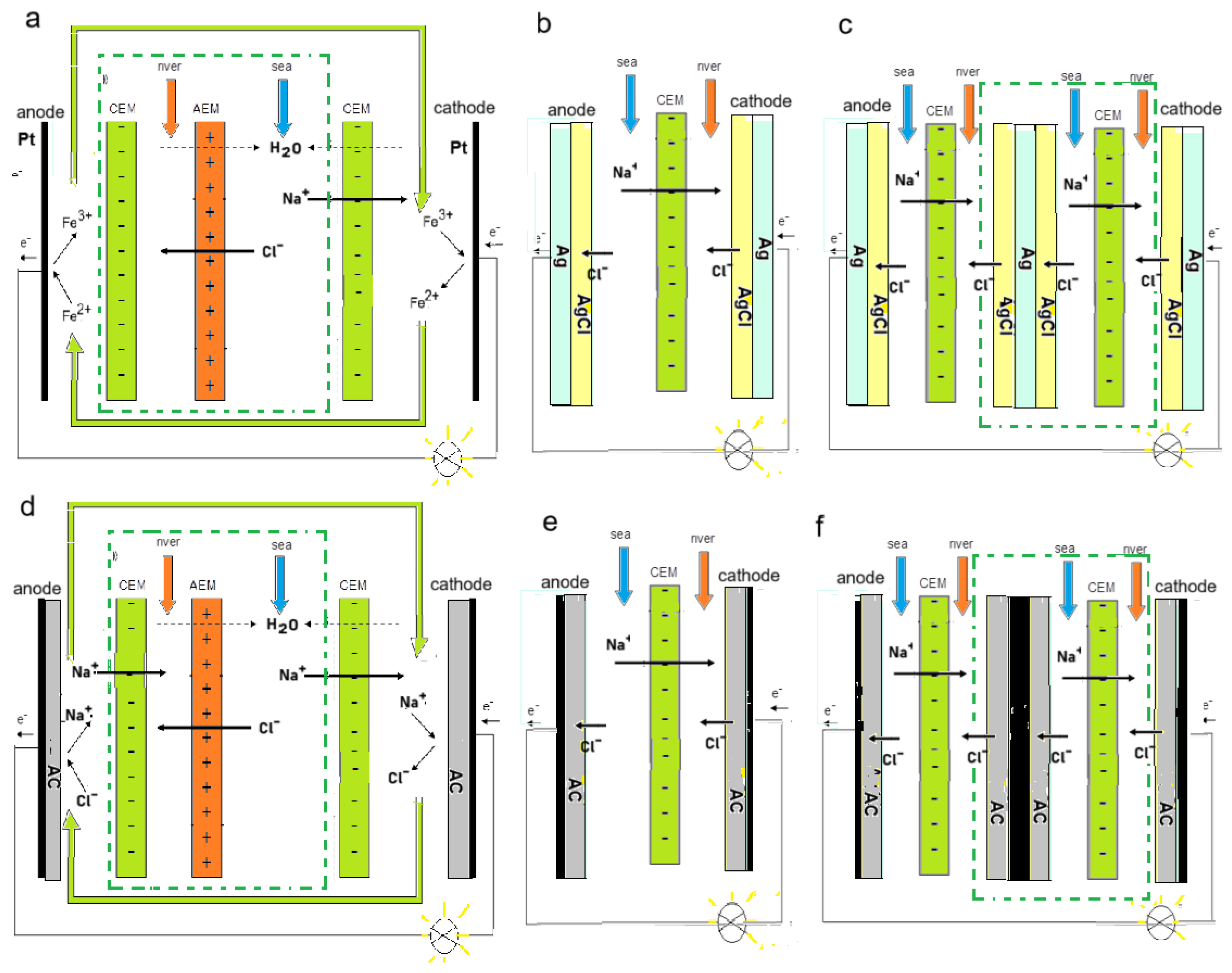
Figure 2.
Different flow directions in a RED stack: (a) co-flow, (b) counterflow, (c) point-to-point cross-flow, (d) cross-flow. Red arrows indicate the flow direction in the river water compartments and blue arrows indicate the direction in the seawater compartments. Modified from [6].
Figure 2.
Different flow directions in a RED stack: (a) co-flow, (b) counterflow, (c) point-to-point cross-flow, (d) cross-flow. Red arrows indicate the flow direction in the river water compartments and blue arrows indicate the direction in the seawater compartments. Modified from [6].
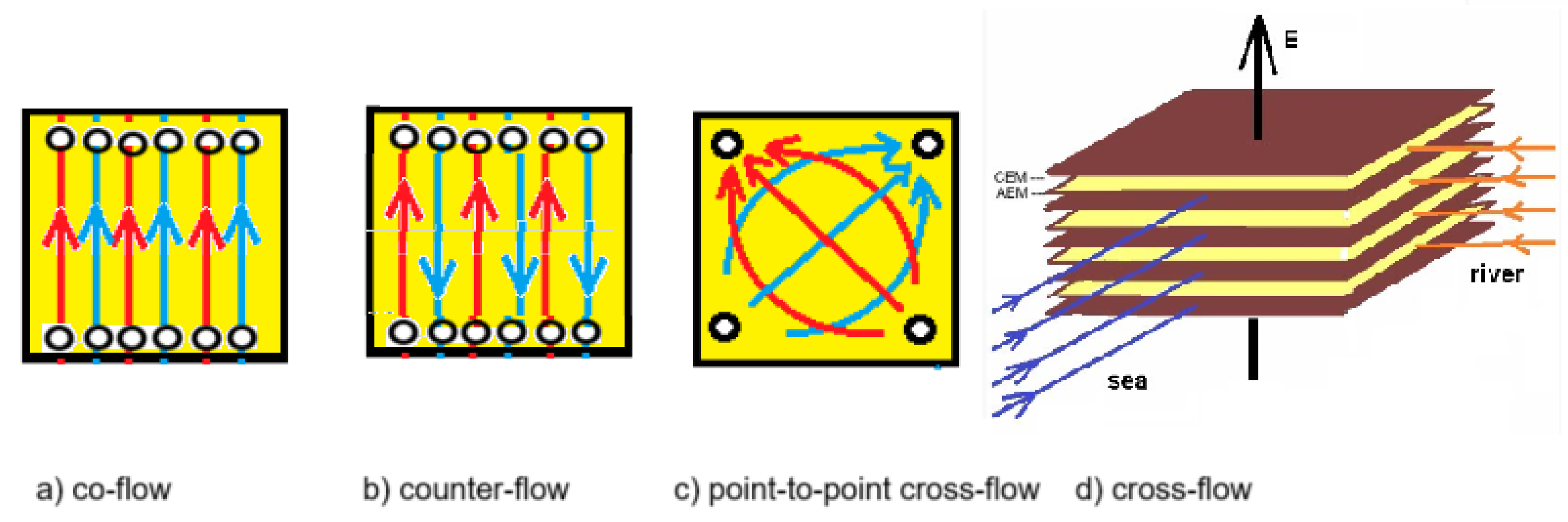
Figure 3.
Pdmem for commercial CEMs and AEMs [15].
Figure 3.
Pdmem for commercial CEMs and AEMs [15].
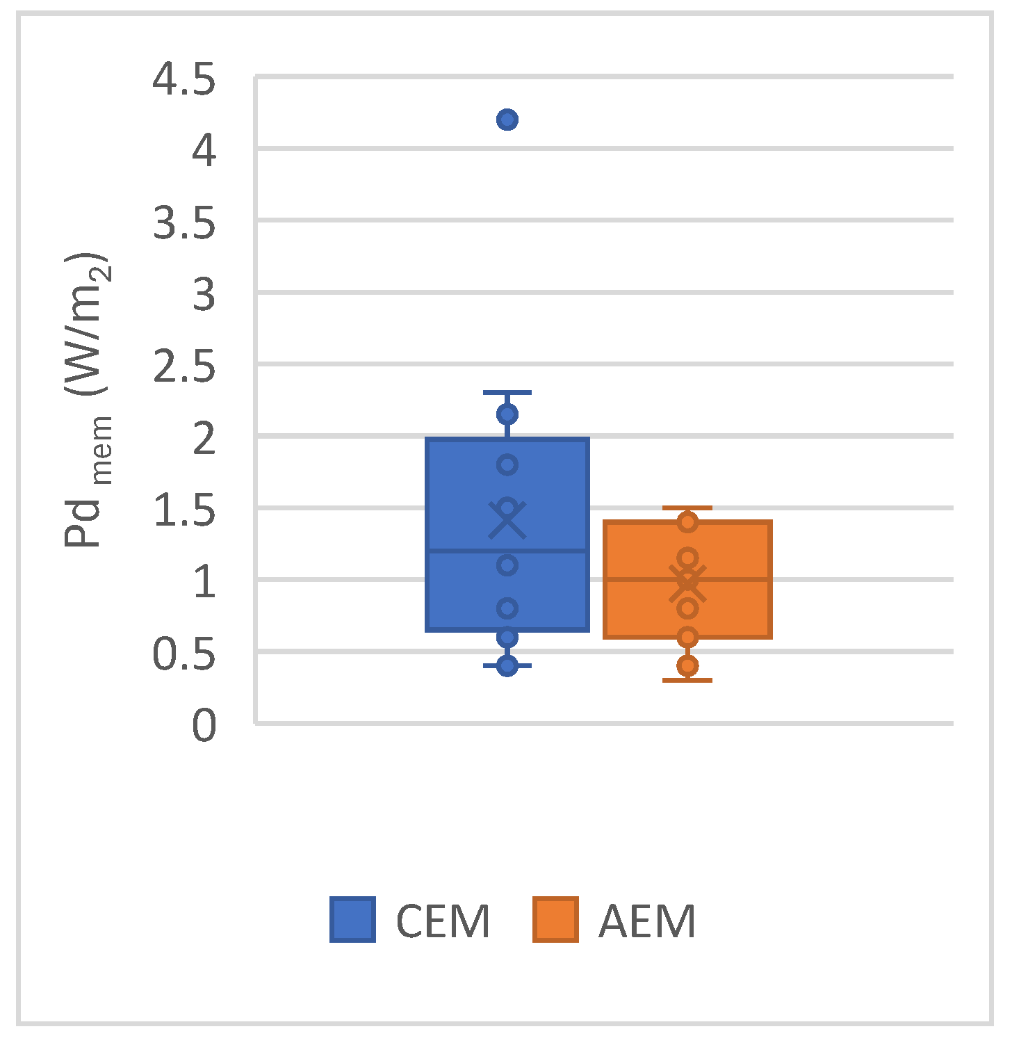
Figure 4.
A RED cell with fractal-profiled membranes. Feed channels are pressed into the membranes (thickness 0.8 mm) until a depth of 0.6 mm. Compartments are pressed with a depth of 0.1 mm. All cell dimensions are arbitrary, for illustration only. From [13]. In this design, all channels are placed within the membranes, realized with one of the profiling techniques (hot pressing, UV curing, screen printing, or casting). A proven technique is hot-pressing of the heterogeneous Ralex membranes [42]. The thickness of the Ralex CEM is 459 μm (dry) and 714 μm (wet) (Table 4).
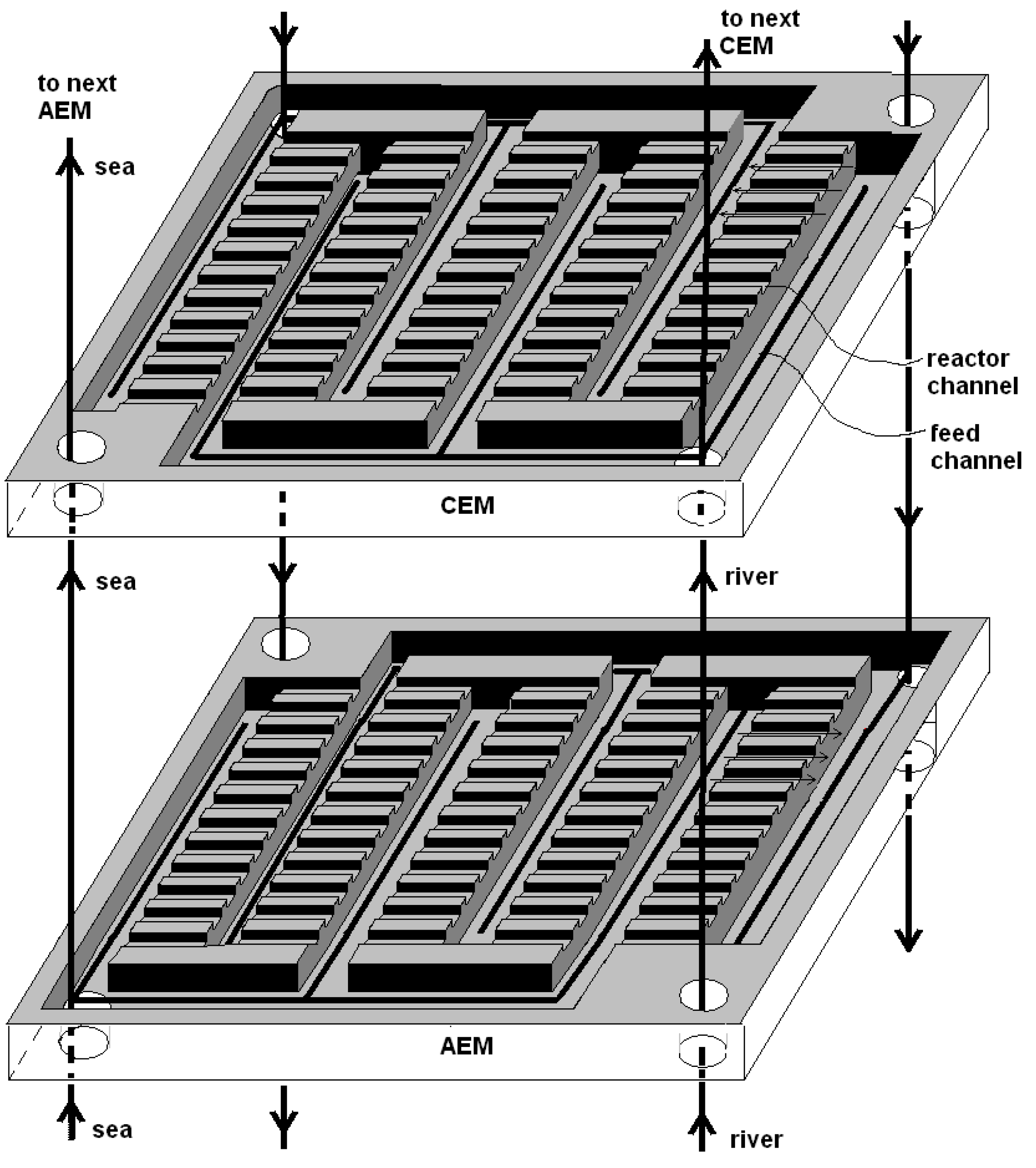
Figure 5.
Areal resistances in Ω∙cm2 for three trajectories through a profiled fractal membrane.
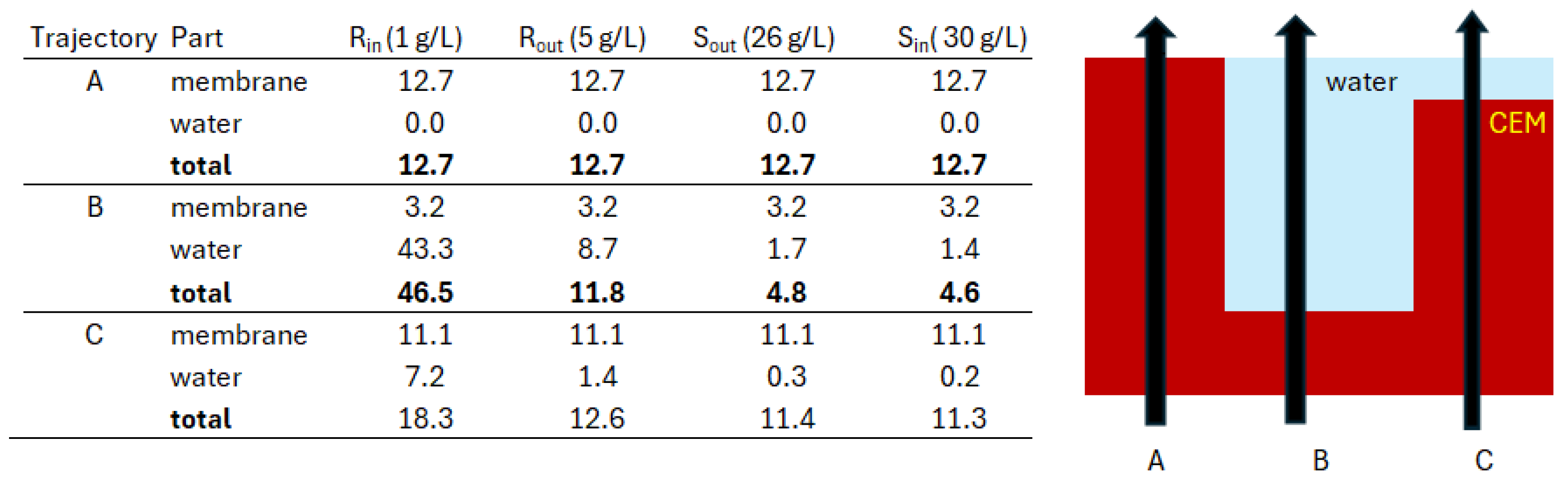
Figure 6.
Some designs for fractal feed within profiled membranes. Membrane thickness is 0.8 mm. Unimpressed parts (sides and ridges) are black, feed channels (yellow) are impressed to a depth of 0.6 mm and reactor channels (blue) are 0.1 mm deep. (a) Flat representation of the membrane from Figure 4, as designed for point-to-point cross-flow feed. (b) Design for a fractal membrane with feedwater supply. Feed channels are wider at the entrance and narrower at the end. (c) The same idea as the previous design but with an alternative design of the feedwater channels.
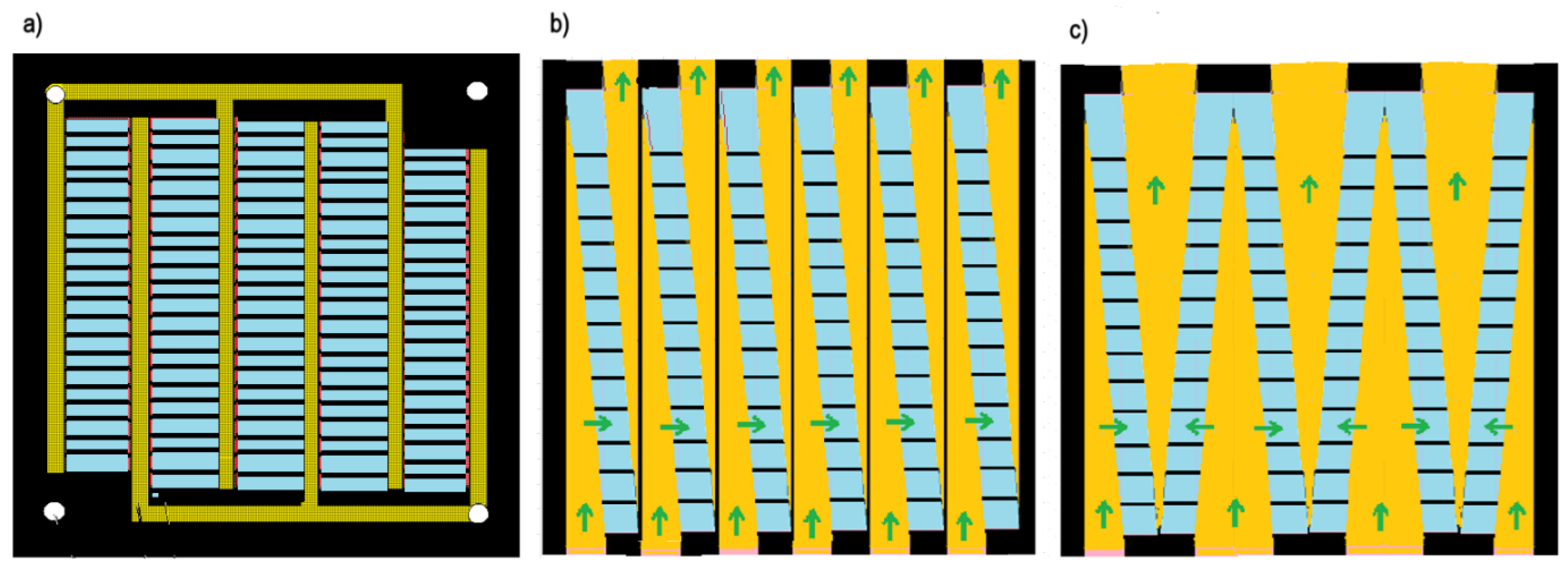
Figure 7.
One feed channel and reactor part from Figure 6b. The width of the feed channels (orange) is adjusted to the decreasing flow rate. The reactor part (blue) is supported by narrow ridges (black). For the calculation, the Ralex CMH-PES is used.
Figure 7.
One feed channel and reactor part from Figure 6b. The width of the feed channels (orange) is adjusted to the decreasing flow rate. The reactor part (blue) is supported by narrow ridges (black). For the calculation, the Ralex CMH-PES is used.
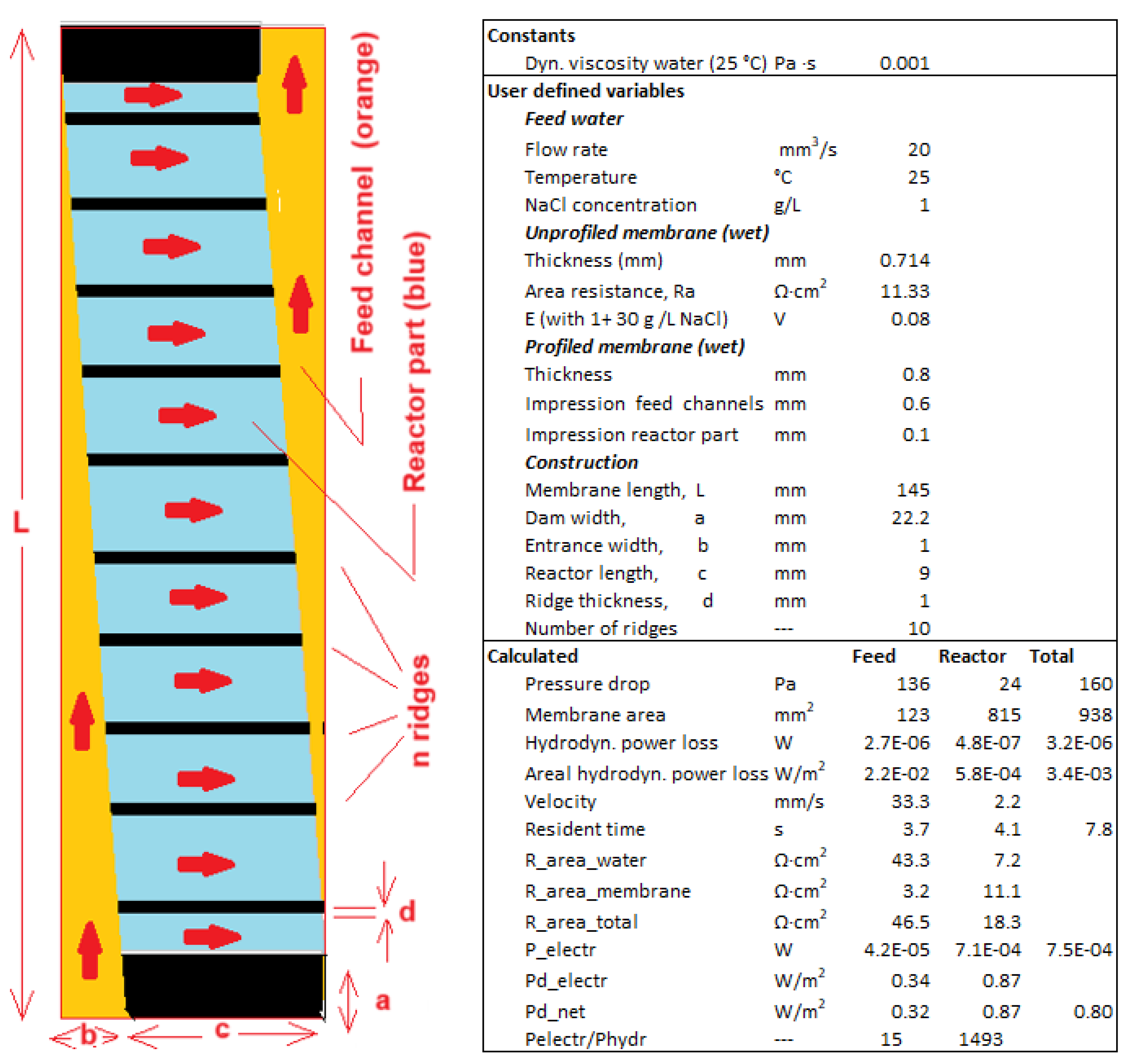
Figure 8.
Fractal stacks.(a) A fractal stack assembled from 16 smaller stacks. Feedwater manifolds are not shown but the sides of the stack are colored according feedwater flow: red (river water inlet), blue (seawater inlet), and gray (river and seawater outlet). (b) Top view of the stack with 16 sub-stacks containing river water feed channels (red), seawater feed channels (blue), and outlet channels (gray). White areas are empty and provide space for tie rods. (c) Top view of a stack with a more efficient ratio between volumes of stacks and feedwater channels. (d) Top view of a stack with an asymmetrical fractal design. Because seawater has a high conductivity, thicker spacers can be applied in the seawater compartments and longer compartments are possible.
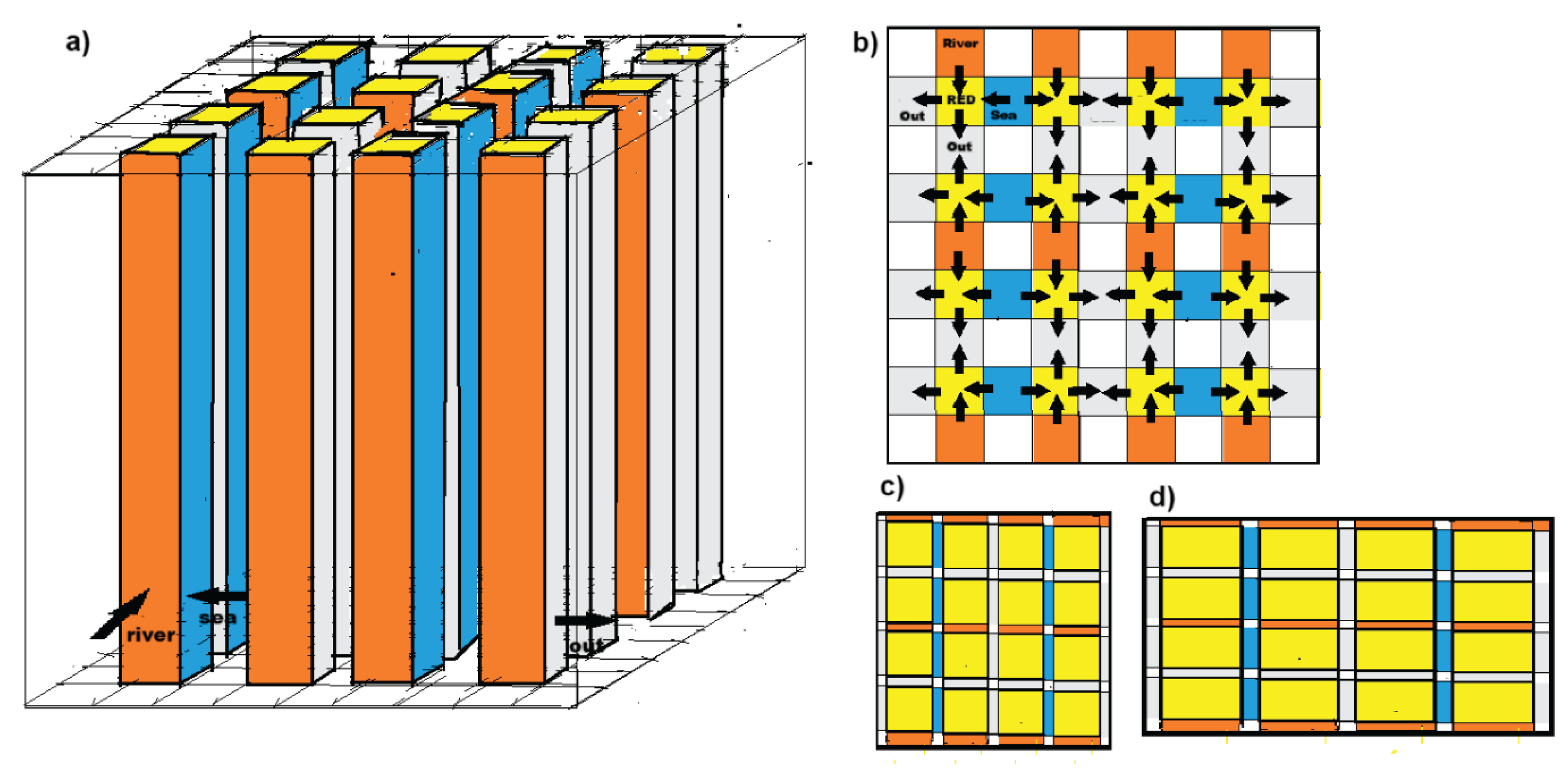
Table 1.
Effect of the length of the flow paths on the net power density in co-flow stacks equipped with real and ideal spacers and membranes. Stacks are optimized for maximum net power density (Pdnet).
Table 1.
Effect of the length of the flow paths on the net power density in co-flow stacks equipped with real and ideal spacers and membranes. Stacks are optimized for maximum net power density (Pdnet).
| Spacer | Membrane | Pdnet (W/m2) | Pdnet (W/m2) | Pdnet (W/m2) |
| @ 0.01 m | @ 0.1 m | @ 1 m | ||
| empty | ideal | 60.2 | 19.0 | 19.0 |
| woven | ideal | 11.58 | 3.66 | 3.66 |
| empty | Qianqiu | 2.43 | 1.91 | 1.91 |
| woven | Qianqiu | 1.63 | 0.99 | 0.99 |
Table 2.
Effect of flow path length of co-flow stacks equipped with Qianqiu membranes and woven spacers. The stack model is maximized for net power density (Pdnet) and for the response product (RPZ).
Table 2.
Effect of flow path length of co-flow stacks equipped with Qianqiu membranes and woven spacers. The stack model is maximized for net power density (Pdnet) and for the response product (RPZ).
| Parameter | - | - | Maximized Pdnet | Maximized RPZ | ||||
| Path length | L (m) | m | 0.01 | 0.1 | 1 | 0.01 | 0.1 | 1 |
| Net power density | Pd_net | W/m2 | 1.63 | 0.99 | 0.47 | 1.05 | 0.74 | 0.38 |
| Net river water yield | Znet | kJ/m3 | 78 | 126 | 156 | 298 | 299 | 272 |
| Flow ratio sea/river water | ΦS/ΦR | - | 0.90 | 1.11 | 1.36 | 5.76 | 3.82 | 3.03 |
| Thickness sea water comp. | δS | μm | 194 | 503 | 1430 | 240 | 590 | 1500 |
| Thickness river water comp. | δR | μm | 96 | 240 | 672 | 54 | 175 | 553 |
Table 3.
Publications in 2024 concerning membranes and micropores for RED (S/R stands for artificial seawater and river water).
Table 3.
Publications in 2024 concerning membranes and micropores for RED (S/R stands for artificial seawater and river water).
| Authors | Ref, | Type | CHC/CLC | Pd (W/m2) | Membrane |
| Liu et al. | [21] | CEM | S/R | 48.4 | Propidium iodide-based two-dimensional polymer |
| Mai et al. | [22] | CEM | 50 | 6.48 | Metal-organic framework |
| Liu et al. | [23] | AEM | S/R | 1.47 | Modified cross-linked alginat hydrogels |
| Guo et al. | [24] | CEM | 50 | 9.2 | Sulfonated poly(ether ether) keton membrane |
| Li et al. | [25] | CEM | 50 | 1.92 | PET-hydrogel heterogeneous membranes |
| Qin et al. | [26] | AEM | S/R | 2.31 | Layered double hydroxide membranes |
| Chen et al. | [27] | CEM | 50 | 10.08 | Zirconium based MOF |
| Awati et al. | [28] | CEM | S/R | 5.35 | VOLD/CNF wrapped carbon nanotubes |
| Cao and Wu | [29] | CEM | 50 | 4.84 | Dual-Network Fiber-Hydrogel Membrane |
| Ren et al. | [30] | CEM | S/R | 21.7 | Oxygen functionalized Mxene |
| Wang et al. | [31] | CEM | 500 | 1.25 | Hole-enriched graphene oxide and cellulose nanofibers |
| Wu et al. | [32] | CEM | 50 | 16.44 | Three-dimensional hydrogel |
| Gu et al. | [33] | CEM | - | 4.66 | Hydrophilic bilayers of vermiculite and Mxene |
| Li et al. | [34] | CEM | 50 | 13.73 | Composite hydrogel |
| Chuang et al. | [35] | CEM | S/R | 9.64 | MOF MIL-178 |
| Lin et al. | [36] | CEM | 500 | 48.5 | Anti-swelling nano-hydrogel |
| Zhou et a.l | [37] | CEM | S/R | 7.7 | Turing-type nanochannels |
| Wu et al. | [38] | CEM | 50 | 30.94 | PASH hydrogel |
| Wei er al. | [39] | CEM | 50 | 21.27 | NaX zeolite |
Disclaimer/Publisher’s Note: The statements, opinions and data contained in all publications are solely those of the individual author(s) and contributor(s) and not of MDPI and/or the editor(s). MDPI and/or the editor(s) disclaim responsibility for any injury to people or property resulting from any ideas, methods, instructions or products referred to in the content. |
© 2025 by the authors. Licensee MDPI, Basel, Switzerland. This article is an open access article distributed under the terms and conditions of the Creative Commons Attribution (CC BY) license (http://creativecommons.org/licenses/by/4.0/).
Copyright: This open access article is published under a Creative Commons CC BY 4.0 license, which permit the free download, distribution, and reuse, provided that the author and preprint are cited in any reuse.


