
Submitted:
08 October 2025
Posted:
08 October 2025
You are already at the latest version
Abstract
In this study, the process of diamond abrasive polishing monocrystalline silicon with circular inclusions was simulated by molecular dynamics. The variation in coordination number, polishing force, friction coefficient, potential energy, polishing temperature, and dislocation were analyzed and studied by changing the size of inclusions in monocrystalline silicon. The analysis of coordination number indicates that the number of silicon atoms with the coordination number of five increases with increasing inclusions, and the atoms mainly gather at the bottom of inclusions; the larger the inclusions, the deeper the subsurface damage; but after polishing, large inclusions increased the number of defective atoms recovered; the analysis of diamond structure revealed that the increase in the diameter of inclusions increases the number of damaged diamond structure atoms. The results show that the polishing force, normal force, and friction coefficient increase with increasing circular inclusion, but the effect of the size of the inclusion on the temperature is not significant; the potential energy of the system first increases obviously and then decreases slowly after reaching the peak; the number and length of dislocations decrease to 0 at first and then increase gradually.
Keywords:
molecular dynamics
; circular inclusion
; coordination number
; polishing mechanism
; dislocation
1. Introduction
Single crystal silicon chips have been widely used in devices from macro to nano level, mainly used for lighting, photoelectric detection, and solar energy conversion, attributing to their high direct bandgap, saturated electron velocity, and electron mobility [1]. However, monocrystalline silicon is type of brittle material with high brittleness, low plasticity, inclusion and crack at ambient temperature, and thus observing the evolution in the processing steps through experiments is very difficult [2]. In addition, carbides exist in most primary silicon crystals to varying degrees, and their amount is related to the carbon content and crystal position in the crystal. Silicon carbide is the most common inclusion. Especially, with the upgrading of electronic technology, national defense and other industries, the nano processing of monocrystalline silicon crystal materials has become a bottleneck problem. The key to solve this problem is to deeply investigate the polishing mechanism of single crystal silicon with defects [3]. Nano machining is mainly realized by nano diamond abrasive particles towards achieving the dimensional accuracy of the structure and the nanometer level size device [4]. Mastering the polishing mechanism of three body abrasive polishing of single crystal silicon can promote the large-scale development of single crystal silicon semiconductor with high precision, high efficiency, and low cost [5].
At present, molecular dynamics method has been used to study the ultra-precision polishing process, leading to significant achievements in material removal and deformation mechanism and machined surface formation mechanism [6,7]. Zhang et al. [8] established the simulation model of diamond cutting single crystal cerium by molecular dynamics simulation method and revealed that the dislocation and slip are the main mechanism of single crystal cerium deformation, and the removal process of single crystal cerium changes from furrow removal to large deformation removal with increasing cutting depth. Yang [9] et al. established a three-dimensional simulation model of diamond abrasive polishing single crystal copper and studied the transformation of single crystal copper removal mode from large deformation removal mode to furrow removal mode with increasing rotation speed. Moreover, the rotation speed of abrasive directly affects the surface quality and internal defect distribution of single copper crystal. Fang [10] et al. established the nanoindentation simulation model of single crystal germanium films and revealed that shear extrusion transformation deformation and dislocation slip are the main deformation mechanisms of single crystal germanium during nanoindentation. Although the material removal mechanism of nano polishing process has been deeply investigated with many outstanding results, the effect of polishing parameters on the material removal mechanism of monocrystalline silicon still needs to be further studied. Zhai [11] et al. found that ultrasonic assisted chemical mechanical polishing can effectively improve the polishing efficiency and surface quality of silicon workpiece. Fang [12] et al. studied the relationship between the shape of fixed abrasive particles and material removal, as well as the effect on the surface quality of single crystal silicon. Goel [13] et al. also investigated the wear mechanism of monocrystalline silicon during single point diamond turning by molecular dynamics simulation.
In contrast, most of the existing simulation studies focus on the ideal defect free crystal materials, but there are some defects such as inclusions, dislocations, and cracks in the actual manufacturing and use process. Defects have attracted the attention of many scholars. Qi and Yang [14] used molecular dynamics and function methods to study circular inclusions and cracks at any position, leading to the following numerical results: the geometry considered localizes underground high energy. In addition, some scholars studied the free vibration of composite films with hexagonal lattice circular inclusions and analyzed the effect of larger inclusion size [15]. Their numerical analysis shows that inclusions have an important effect on their research. Mattoni [16] et al. proved that the interaction between microcracks and hard inclusions (fibers) can improve the mechanical properties β-SiC. The strength of SiC lattice is beyond the linear range. They used surface elasticity to study the surface effect of defects on the deformation of composites. Luo and Wang [17] used the complex function method to analyze the stress field near an elliptical cylindrical inclusion with interface effect and its interaction with screw dislocation under in-plane shear loading. Mogilevskaya et al. [18,19] also used the complex function method to calculate the interaction between nano cylindrical inclusions with interface effect in infinite and semi-infinite bulk. However, the evolution mechanism of nano polishing process cannot be observed by experiments and numerical simulation. Moreover, continuum mechanics cannot be used to analyze the process of nanofabrication, thus necessitating to study the mechanism of nanofabrication from the perspective of atoms and molecules. Molecular dynamics simulation plays the role of bridge between macro characteristics and microstructure and has become the most important simulation method. Therefore, studying the polishing process of single crystal silicon with inclusions by molecular dynamics simulation is of great theoretical and practical value.
In this study, a model of polishing monocrystalline silicon workpiece with diamond abrasive particles containing different diameter silicon carbide inclusions was established, and the basic polishing characteristics, i.e., the effect of the size of silicon carbide inclusions on friction coefficient, flatness, and material removal rate was studied by molecular dynamics simulation. At the same time, the morphology of the workpiece surface and the damage of the sub surface were observed, and the thermodynamic information and mechanical properties were analyzed to understand the polishing mechanism of single crystal silicon with inclusion defects.
2. Molecular Dynamics Polishing Model
2.1. Building a System Model
In the early 1990s, BELAK et al. [20] first proposed the molecular dynamics simulation model of nanofabrication, which is still of widely used. The molecular dynamics model of three-dimensional diamond abrasive polishing monocrystalline silicon established in this study is shown in Figure 1. This model comprises a rigid diamond abrasive and a monocrystalline silicon workpiece containing silicon carbide inclusions. In the simulation process, the diamond abrasive was considered to be absolutely rigid, i.e., there will be no wear and deformation. Monocrystalline silicon workpiece consists of Newton layer, thermostat layer, and boundary layer. Among them, the boundary layer atoms are fixed to ensure lattice symmetry; the Newton layer atoms follow Newton’s second law; the thermostat layer was introduced to ensure that the heat generated in the polishing process can be transferred out in time, and the layer atoms are scaled to ensure constant temperature. The whole process was carried out under the NVE ensemble.
In order to accurately measure the thermodynamic changes such as temperature and potential energy in the polishing process, a measurement region, with the size of 8*11*16.29 nm3 along the X, Y, and Z directions, respectively, was established in the Newton layer. Before polishing, the preset distance between the abrasive particles and the workpiece is 1 nm, and the polishing depth is 4 nm. In order to study the effect of the size of inclusions in monocrystalline silicon on the material removal mechanism and sub surface formation mechanism in the polishing process, three control groups were set up in this simulation: the diameter of SiC inclusions were d = 3, 4, and 5 nm. The spherical inclusion is located at (200 122.9 81.45) (unit Å). The specific parameters of the model are listed in Table 1. The polishing process is divided into two steps: (i) relaxation process, (ii) polishing process. The relaxation of 100,000 time steps led to a stable workpiece. After that, the abrasive particles are polished along the [- 100] direction of the (001) surface of the workpiece at a spin speed of 100 m/s and a feed speed of 200 m/s. The polishing speed is much faster than the real polishing speed, with two purposes: (i) save operation time; (ii) improve the material removal efficiency.
2.2. Potential Function for Determining System Interactions
The interaction force was obtained by the derivation of the interaction potential between atoms. In molecular dynamics simulation, the selection of potential function directly determines the calculation workload and the approximation of the calculation model with the real system. In order to balance the accuracy and time in molecular dynamics simulation, nano processing is investigated by the empirical potential function method. There are many empirical potential functions, among which, the potential functions involved in single crystal materials can be divided into: (1) potential pairs; for example, the potential functions of L-J [22], EAM [23], Morse [24] are mainly applicable to single crystal copper and single crystal aluminum crystal; (2) multi body potential. For example, Tersoff [25], ABOP [26], Stillinger-Weber [27] and other multi body potential functions [28], applicable to single crystal silicon and single crystal germanium. Most researchers define diamond abrasive particles as rigid bodies, thus ignoring the interaction between carbon atoms in diamond abrasive particles, and diamond abrasive particles are also set as rigid bodies in this simulation. Morse potential function is simple in form and less expensive to calculate and is often used to describe the interaction between workpiece and abrasive atom (C–Si). Because of the very unstable structure of brittle materials , it cannot be expressed by simple potential function. In order to stabilize the crystal structure, the bond angle between three or more atoms must be considered in each step of calculation. Based on quantum mechanics, Tersoff potential function [29] considers that the strength of bond depends on its own environment, especially the more adjacent the atoms, the weaker the bond. In general, the multi body empirical potential of Morse potential function can more accurately describe the interaction force between atoms in a covalent system. Therefore, in this simulation, SiC_Erhart-Albe.tersoff was used to describe the atomic interaction (Si–Si, Si–C) in silicon carbide inclusions; Morse potential function is used to describe the interaction between abrasive atoms and workpiece atoms and the interaction between abrasive atoms and inclusion atoms. Other specific data are shown in Table 2.
2.3. Numerical Calculation of the System
In molecular dynamics simulation process, all atoms except the boundary layer conform to Newton’s second law [30]. Newton’s equations of motion were established to describe and simulate a pair of atoms i and j in the system, and their coordinates, velocities, and interaction forces at time t were analyzed as As shown by Eqs. (1), (2), and (3).
Velocity Verlet algorithm is widely used owing to its advantages of location and speed synchronization, low memory consumption, and parallel computing. Therefore, the Velocity Verlet algorithm with a time step of 1 fs was used to solve the above-mentioned second-order differential equations, leading to Eqs. (4), (5), and (6). represents the potential interaction function.
According to the actual simulation, the molecular dynamics simulation time is mainly focused on the calculation of the interaction between atoms. In order to shorten the simulation time without reducing the calculation accuracy, the truncation radius method is usually used to reduce the calculation time of the interaction between molecules. In this study, 2.6 Å was used as the truncation radius [31].
3. Results and Discussion
The effect of the diameter of round silicon carbide inclusions on the polishing process is discussed in this section. The coordination number, polishing force, friction coefficient, potential energy, polishing temperature, diamond structure surface morphology, and dislocation were analyzed in detail. The simulation results of this study are all from MD simulation of open-source software LAMMPS [32]. The MD simulation results were visualized by OVITO software [33] and processed by origin.
In the process of polishing, temperature is a very important physical characterization for studying polishing mechanism. The temperature is calculated according to the following formula [34]: . Where N represents the number of atoms, is the velocity of the ith atom, is the Boltzmann constant, and T represents the atomic temperature. The temperature changes mainly because of the friction and extrusion between diamond abrasive and single crystal wafer. In addition, inclusions in monocrystalline silicon also have an important effect on temperature. The change in the polishing temperature not only affects the service life of abrasive particles, but also affects the surface and sub surface quality of the workpiece to be polished. Therefore, the study of the change in polishing temperature is an important aspect of the study of material removal and surface formation mechanism. In order to better understand the evolution mechanism of the polishing process from the perspective of polishing temperature, as shown in Figure 2 (a), the polishing temperature increases with increasing polishing distance. Obviously, the larger the diameter of the inclusion causes the higher the polishing temperature in the measurement area. This is very well understood, because the larger the diameter of the inclusion, the larger the contact area and contact stress between the abrasive particles and the inclusion during polishing, increasing the extrusion shear deformation of the workpiece, and the energy released by the workpiece will increase accordingly, increasing the temperature change. However, the effect of the size of inclusions on the temperature difference is not very obvious. The main reason for the temperature change is the extrusion and friction of the abrasive particles and workpieces. Figure 2 (a) shows that the temperature difference caused by the size of inclusions increases when polishing to the 8 nm position, because the number of atoms in bct-5 and Si-II (CN=6) increases, the fracture of atomic bond, lattice deformation, and reconstruction increase the temperature. Notably, the temperature rises sharply and fluctuates in the initial stage of polishing because of the inclusion in the workpiece. Then, the grinding particles move forward, and the temperature changes tend to be stable. Obviously, when the abrasive particles move to the top of the inclusion, the inclusion makes the polishing process generate more heat, and the larger the inclusion, the more heat will be generated.
The potential energy of the measurement area varies with the polishing distance as shown in Figure 2 (b), indicating that when the polishing distance is less than 14 nm, the potential energy rises rapidly; when the polishing distance is more than 14 nm, the potential energy decreases, and tends to be in dynamic balance with the polishing process. When the diamond abrasive particles just contact the monocrystalline silicon atom, the covalent bond of the silicon atom is broken because of the squeezing of the silicon atom before and below the grinding grain. Moreover, the energy generated by the plough of diamond abrasive grains will be stored in the lattice of silicon in the form of lattice deformation energy, thereby the induced potential energy increases rapidly. Then, the potential energy decreases slowly because of the energy consumption of crystal reconstruction and elastic recovery of the machined surface. With increasing polishing process time, the potential energy tends to be in stable dynamic equilibrium state. It is worth noting that the potential energy is different in the initial stage of polishing, because of the difference of the size of inclusions. The larger the diameter of the inclusions, the smaller the initial potential energy, and the lower the average value of the potential energy. Figure 2 (b) also shows that after entering the polishing process, the potential energy increase rate of the system increases with increasing number of inclusions, because the effect of abrasive particles and inclusions increases with increasing number of inclusions; therefore, the number of atoms removed will increase, the lattice deformation of atoms and the energy released by amorphous phase transition increase, eventually increasing the potential energy change of the system.
In the nano polishing process, the main source of polishing force is the interaction between abrasive atoms and silicon workpiece atoms. In this study, the source of polishing force is not only the interaction between abrasive atoms and workpiece, but also the size of inclusions in workpiece. The polishing force is mainly composed of normal force and tangential force. Figure 3 (a) and (b) show the curves of tangential force and normal force varying with polishing distance, respectively, indicating that: (1) in the polishing process, the variation trend of tangential force and normal force is similar with some fluctuations; (2) in the initial stage of polishing, the growth rate of tangential force and normal force is higher, but the growth rate of the normal force is greater than the tangential force. When polishing to 10 nm, the force tends to be in a stable dynamic equilibrium, and the dynamic equilibrium value of normal force is greater than the tangential force. The crystal deformation and reconstruction of silicon atoms and the internal inclusions are the main reasons for the fluctuation. The elastic recovery of the machined surface also has a certain influence on it. Because of the inclusion in the workpiece, the normal force will be opposite to the normal force in the polishing process, resulting in a higher average value of the normal force. Because of the fluctuation of the force curve, the average force (tangential force and normal force) as shown in Figure 3 (c) is plotted to better represent the effect of different size inclusions on the force. Figure 3 more intuitively shows that the average normal force is greater than the average tangential force. The average force increases with increasing inclusion diameter. The friction coefficient is mainly used to characterize the ability of diamond particles to remove silicon surface materials. Figure 3 (d) shows that the friction coefficient increases with increasing number of inclusions. In the absence of any inclusion in monocrystalline silicon workpiece, the friction coefficient of monocrystalline silicon polished by diamond abrasive can reach 0.797 [35]. This study proved that the a certain size of inclusions in the workpiece can reduce the friction coefficient and increase the machinability of the material.
Different coordination numbers represent different crystal phases, which in turn leads to monocrystalline silicon with different properties. Therefore, the study of phase transition structure plays an important role in revealing the mechanism of mechanical polishing. According to Goel and Luo et al. [34], the transformation process between different phases under contact load is shown in Figure 4. In this study, SI-I phase is an atom with CN = 4; bct-5 phase is an atom with CN = 5; Si-II phase is an atom with CN = 6; and atoms with coordination number 7 or more is high pressure phases. The effect of inclusion diameter on the atomic phase transformation during polishing was investigated, the diagram of phase transformation atoms with polishing distance is shown in Figure 5. Obviously, the number of defect atoms in different phases increases with increasing polishing distance. With the progress of polishing distance, the diamond particles squeeze and rub the workpiece forward and downward, causing atomic bond fracture and lattice reconstruction of silicon atoms. Figure 5 (a) shows the evolution trend of atoms of bct-5 phase (CN = 5) with polishing distance when the diameter of SiC inclusion in silicon workpiece is different. Although the variation curves of the number of atoms in bct-5 phase are almost intertwined with each other at different inclusion diameters, the evolution trend is nearly the same. Larger inclusion diameter produced more defect atoms. The main reason for the formation of bct-5 phase (CN = 5) atoms is the stress concentration in the workpiece, and the increase in the inclusion size is the main reason for the increase of bct-5 phase atoms. In brief, the larger the diameter of the inclusion, the larger the stress concentration area, resulting in more bct-5 phase atoms. Figure 5 (b) and (c) show the changes of Si-II phase (CN = 6) atoms and high-pressure phase atoms, respectively. In the polishing process, the bct-5 phase (CN = 5) has the most atoms and the Si-II phase (CN = 6) has the least, because the Si-II phase silicon atoms are reversible and unstable, and is easy to transform into other phase atoms in the polishing process, also explaining the fluctuation of the number of silicon atoms with the coordination number of 6 and the reason of the least number. High temperature and high pressure near the abrasive particles are the main reasons for the occurrence of atoms with coordination number greater than or equal to 7. Figure. 5 (c) shows that the larger the inclusion diameter is, the fewer the number of atoms with a ligand greater than or equal to 7. Wang et al. [36] showed a certain degree of damage on the surface of the workpiece, which can in turn enhance the machinability of the workpiece. The presence of inclusions will cause atomic defects in the workpiece and reduce the cutting force, improve the extreme conditions near the abrasive particles, and reduce the generation of high-pressure phase atoms. Therefore, silicon carbide inclusions with a certain size can improve the machinability of monocrystalline silicon and reduce the surface and subsurface damage caused by machining.
The previous study of coordination number indicated that changing the diameter of SiC circular inclusion has an important effect on the coordination number of monocrystalline silicon. The distribution of atoms with different coordination endows different properties and surface characteristics of the workpiece. Herein, the inclusion diameters of 3 nm and 5 nm were chosen to study the effect the inclusion diameter on the surface morphology of the workpiece. As shown in Figure 6, when the inclusion diameter is 3 nm, the silicon atoms with different coordination numbers evolve with the polishing process. A comparison with Figure 7 shows that the larger the diameter of inclusions, the more atoms of bct-5 phase (CN = 5) and Si II phase (CN = 6) are produced when diamond grains contact with inclusions in the workpiece. The forward movement of the abrasive above the inclusion produces a large number of CN ≥ 7 phase atoms. The larger the diameter of the inclusion is, the CN≥ 7 phase atoms are produced, because the circular inclusion is directly under the abrasive particles, causing stress concentration, and a large number of high-pressure phase atoms are produced in the high-temperature and high-pressure environment. When the abrasive particles just contact with the circular inclusion, the defect atoms are mainly concentrated in the contact position of the abrasive particles and the circular inclusion. At this time, the bct-5 phase (CN = 5) atoms produced by the smaller inclusion are more than those produced by the inclusion with a diameter of 5 nm. When the abrasive particles move directly above the circular inclusion, the larger the diameter of the inclusion is, the more defect atoms are produced below the inclusion. In addition, the large inclusion leads to increased number of defect atoms in the subsurface layer after abrasive polishing. When the abrasive particles move to the final state, a large number of atoms of bct-5 phase (CN = 5) still gather under the inclusion when the inclusion is large, while the number of atoms of bct-5 phase (CN = 5) under the inclusion with small inclusion is less. The increase in inclusion size has little effect on the accumulation of surface materials and the height of surface bulge, and the inclusion mainly affects the subsurface damage depth of the workpiece. Figure 8 shows the subsurface damage depth in the final state at the inclusion diameters of 3, 4, and 5 nm. Obviously, the larger the inclusion diameter is, the deeper the subsurface damage depth is. In contrast, with increasing number of inclusions, no significant chip accumulation was observed on the surface of the silicon workpiece, i.e., there are certain inclusions in the silicon workpiece, which will not reduce its surface quality. Figure 8 shows that the damaged atoms are mainly concentrated in the contact area between the abrasive particles and the workpiece, among which the atoms of high-pressure phase (CN ≥ 7) and Si II phase (CN = 6) are the most significant, and some of the atoms of bct-5 phase (CN = 5) are located at the bottom of the abrasive polishing position and some around the impurity. With the movement of the abrasive particles, the atomic lattice of the silicon workpiece is squeezed by the polishing force, and the surface atoms are pushed by the abrasive particles. With the progress of polishing, the interaction between abrasive particles and inclusions intensifies, and the energy generated by lattice deformation is stored in the lattice of single crystal silicon. When the stored energy reaches a certain value but is not enough to form dislocation, the silicon atomic bond breaks, leading to lattice reconstruction and generation of more silicon atoms with different coordination numbers. With the increasing polishing time, subsurface gets damaged.
In order to distinguish hexagonal structure from the diamond structure, the second layer neighbor particles are considered in the method of identifying diamond structure. Common neighbor analysis (CNA) is usually used to distinguish FCC, HCP, and BCC structures, but it is not suitable to distinguish diamond structures, because there is no common neighbor between the first layer neighbors, and the second and third layers cannot be well distinguished. Because of the changing diameter of the inclusions at the same position in the polishing process, the motion process of the inclusions is similar to the evolution process of the damaged atoms. This part only discusses the final polishing effect in the case of d = 3 nm and 5 nm. Figure 9 (a) and (b) show the final state of the workpiece after interaction with the abrasive at the inclusion diameters of 3 and 5 nm, respectively. Obviously, the larger the diameter of the inclusion is, the more atoms of diamond structure will be destroyed. The larger the size of inclusions, the more prominent the stress concentration in the workpiece, and the more strong the interaction among the workpiece, abrasive particles and inclusions, destroying the diamond structure of the workpiece. Although the inclusion moves slightly along the polishing direction, it does not damage the diamond structure of SiC inclusion. Figure 9 shows that in the cubic diamond, the neighboring atoms of the first and second layers are arranged according to the lattice of BCC diamond. Cubic diamond (1st neighbor) means that the four neighbor atoms of the first layer are arranged according to cubic diamond, but at least one of the second layer is not. Cubic diamond (2nd neighbor) indicates that at least one of the first layer is missing or not in the lattice position. Other means hexagonal diamond structure and unknown coordination structure. In order to quantify the number of atoms in the damaged diamond structure, the pie chart as shown in Figure 9 (c) and (d) was drawn according to the silicon atoms of different structure types to indicate their proportion. A comparison of Figure 9 (c) and (d) indicated that increasing diameter of inclusions will indeed increase of the number of atoms in the damaged diamond structure. Therefore, in order to improve the surface quality of the workpiece after polishing, the presence of larger inclusions should be avoided.
The DXA (dislocation extraction algorithm) analysis of the simulation results lead to the following correct position error views. Figure 10 shows the number of dislocations in the atoms inside the silicon carbide workpiece with SiC inclusions and the total length of the dislocation segments changing with the polishing progress. The total length and number of dislocation segments decrease first and then increase. With increasing diameter of SiC inclusions, the number of dislocations increases, and the total length of dislocation section increases. The difference between the number of dislocation segments and the total length of the dislocation segments in the initial polishing period is smaller, mainly because the diamond abrasive particles have not been strongly affected by the internal inclusions; when polished to 9–12 nm, the number and total length of dislocation segments decreased to 0. Elastic recovery occurs during this period; then, with increasing inclusions, the difference between the number of dislocation segments and the total length is more and more obvious. In conclusion, the smaller the diameter of the inclusions, the less the number of dislocations and the shorter the total length of the dislocation section.
Figure 11, Figure 12 and Figure 13 (A1) shows dislocation graphs at the initial stage of polishing when the inclusion diameter is 3, 4, and 5 nm respectively. With increasing inclusion diameter, the total length of dislocation section is larger. Although the inclusions are the smallest, the dislocation types are the most. The dislocation diagram of the polishing medium period is shown in Figure 11-13 (B1) when the inclusion diameter is 3, 4, and 5 nm. At this time, the number of dislocations in three cases is very small. The dislocation diagram at the end of polishing is shown in Figure 11-13 (C1) after the completion of the polishing at the inclusion diameters of 3, 4, and 5 nm. When the diameter of the inclusion is 3 nm, the number of dislocations is very small; when the diameter of the inclusion is 4 nm, there are a lot of complex dislocation segments at the end of polishing, and the dislocation segments with Burgers vector of 1/6 < 110 > appear. The results show that the number and total length of dislocation segments increase with increasing number of inclusions.
4. Conclusions
In conclusion, a molecular dynamics simulation model of monocrystalline silicon with circular inclusions in diamond nano polishing was established by the molecular dynamics method. The effects of changing the size of inclusions in silicon workpiece on potential energy, temperature, polishing force, surface morphology, coordination number, and dislocation were studied and analyzed. The following conclusions can be drawn from this study:
(1) The larger the size of inclusions in the workpiece, the deeper the subsurface damage. The increase in inclusion size will increase the damage of diamond structure. At the same time, polishing process releases more heat, increasing the temperature, but to a certain extent, it can reduce the potential energy generated in the polishing process.
(2) The polishing force and normal force increase with increasing inclusion size. The larger the inclusion size is, the larger the friction coefficient is. However, the presence of a certain size of inclusions in the workpiece can reduce the friction coefficient and increase the machinability of the material.
(3) The defect atoms in the workpiece mainly exist in bct-5 phase, and the larger size of the inclusion results in a large number of bct-5 phase (CN = 5) atoms under the inclusion. The larger the inclusion diameter is, the less high-pressure phase (CN ≥7) atoms are produced, which can improve the machinability and surface quality of silicon workpiece.
(4) The DXA analysis shows that the smaller the diameter of the inclusion, the less the number of dislocations and the shorter the length of the dislocation segment. With increasing diameter of the inclusion, the more dislocation types and the more dislocations are produced.
Author Contributions
Yue haixia; Conceptualization. Tang Song, Chen xiaoqin and Tan yan; date curation.Dai houfu and all authors reviewed and approved the final manuscript. Wei song; visualization
Funding
①the Science and Technology Research Program of Chongqing Municipal Education Commission (KJQN202503509) ②National Natural Science Foundation of China (12162008, 52105178), ③Guangdong Provincial Natural Science Foundation General Project (2025A1515011447)
Data Availability Statement
Data will be made available on request.
Conflicts of Interest
The authors declare that they have no known competing financial interests or personal relationships that could have appeared to influence the work reported in this paper.
References
- Saga, T. Advances in crystalline silicon solar cell technology for industrial mass production. NPG Asia Mater. 2010, 2, 96–102. [Google Scholar] [CrossRef]
- Lee, H.; Park, S.; Jeong, H. Evaluation of environmental impacts during chemical mechanical polishing (CMP) for sustainable manufacturing. Journal of Mechanical Science & Technology 2013, 27, 511–518. [Google Scholar]
- Liang, B.; Liu, Y.; Xu, Y. Silicon-based materials as high-capacity anodes for next generation lithium ion batteries. Power Sour. 2014, 267, 469–490. [Google Scholar] [CrossRef]
- Lee, R.W.; Wang, H.; To, S.; Cheung, C.F.; Chan, C.Y. Mesoplasticity Approach to Studies of the Cutting Mechanism in Ultra-precision Machining. Chinese Journal of Mechanical Engineering 2014, 27, 219–228. [Google Scholar] [CrossRef]
- Wang, J.; Fang, F.; Zhang, X. Nanometric Cutting of Silicon with an Amorphous-Crystalline Layered Structure: A Molecular Dynamics Study. Nanoscale research Letters 2017, 12, 41. [Google Scholar] [CrossRef] [PubMed]
- Xu, F.; Fang, F.; Zhang, X. Hard particle effect on surface generation in nano-cutting. Applied Surface Science 2017, 425, 1020-1027. [Google Scholar] [CrossRef]
- Wu, Z.; Liu, W.; Zhang, L. Revealing the deformation mechanisms of 6H-silicon carbide under nano-cutting. Computational Materials Science 2017, 137, 282–288. [Google Scholar] [CrossRef]
- Zhang, J.; Shuai, M.; Zheng, H.; Li, Y.; Jin, M.; Sun, T. Atomistic and Experimental Investigation of the Effect of Depth of Cut on Diamond Cutting of Cerium. Micromachines 2018, 9, 26. [Google Scholar] [CrossRef]
- Yang, Y.; Zhao, H.; Zhang, L.; Shao, M.; Liu, H.; Huang, H. Molecular dynamics simulation of self-rotation effects on ultra-precision polishing of single-crystal copper. AIP Advances 2013, 3, 100. [Google Scholar] [CrossRef]
- Zhu, P.Z.; Fang, F.Z. Molecular dynamics simulations of nanoindentation of monocrystalline germanium. Applied Physics A 2012, 108, 415–421. [Google Scholar] [CrossRef]
- Zhai, K.; He, Q.; Li, L.; et al. Study on chemical mechanical polishing of silicon wafer with megasonic vibration assisted. Ultrasonics 2017, 80, 9–14. [Google Scholar] [CrossRef]
- Fang, C.; Zhao, Z.; Lu, L.; Lin, Y. Influence of fixed abrasive configuration on the polishing process of silicon wafers. International Journal of Advanced Manufacturing Technology 2016, 88, 1–10. [Google Scholar] [CrossRef]
- Goel, S.; Luo, X.; Reuben, R.L. Wear mechanism of diamond tools against single crystal silicon in single point diamond turning process. Tribology International 2013, 57. [Google Scholar] [CrossRef]
- Qi, H.; Yang, J. Dynamic analysis for circular inclusions of arbitrary positions near interfacial crack impacted by SH-wave in half-space. Eur. J. Mech. - A/Solids 2012, 36, 18–24. [Google Scholar] [CrossRef]
- Andrianov, I.V.; Awrejcewicz, J.; Markert, B.; Starushenko, G.A. Analytical Homogenization for Dynamic Analysis of Composite Membranes with Circular Inclusions in Hexagonal Lattice Structures. Int. J. Struct. Stab. Dyn. 2017, 17. [Google Scholar] [CrossRef]
- Mattoni, A.; Colombo, L.; Cleri, F. Atomistic study of the interaction between a microcrack and a hard inclusion in beta-SiC. Physical Review B 2004, 70, 094108. [Google Scholar] [CrossRef]
- Luo, J.; Wang, X. On the anti-plane shear of an elliptic nano inhomogeneity. Eur. J. Mech. A/Solid 2009, 28, 926–934. [Google Scholar] [CrossRef]
- Mogilevskaya, S.G.; Crouch, S.L.; Stolarski, H.K. Multiple interacting circular nano-inhomogeneities with surface/interface effects. J. Mech. Phys. Solids 2008, 56, 2298–2327. [Google Scholar] [CrossRef]
- Jammes, M.; Mogilevskaya, S.G.; Crouch, S.L. Multiple circular nano-inhomogeneities and/or nano-pores in one of two joined isotropic elastic half-planes. Eng. Anal. Boundary Elem. 2009, 33, 233–248. [Google Scholar] [CrossRef]
- Belak, J.; Boercker, D.B.; Stowers, I.F. Stowers. Simulation of Nanometer-Scale Deformation of Metallic and Ceramic Surfaces. MRS Bulletin 1993, 18. [Google Scholar] [CrossRef]
- Dai, H.; Li, S.; Chen, G. Comparison of subsurface damages on mono-crystalline silicon between traditional nanoscale machining and Laser-assisted nanoscale machining via molecular dynamics simulation. Nuclear Instruments & Methods in Physics Research 2018, 414, 61–67. [Google Scholar]
- Natchimuthu, V.; Jayalatha, K.A.; Ravi, S. Characterizing the molecular interaction of perfluorocarbons with carbamazepine and benzodiazepine using photo-acoustic studies. J. Mol. Liq. 2016, 218, 120–127. [Google Scholar] [CrossRef]
- Huang, P.H.; Wu, Y.F. Molecular Dynamics Studies of Cold Welding of FCC Metallic Nanowires. Adv. Mater. Res. 2014, 2949, 1367–1371. [Google Scholar] [CrossRef]
- Wang, Y.; Xu, J.; Zhang, J.; Chen, Q.; Ootani, Y.; Higuchi, Y.; Kubo, M. Tribo-chemical reactions and graphitization of diamond-like carbon against alumina give volcano-type temperature dependence of friction coefficients: A tight-binding quantum chemical molecular dynamics simulation. Carbon 2018, 133, 350–357. [Google Scholar] [CrossRef]
- Zhou, P.; Sun, T.; Shi, X.; Li, J.; Zhu, Y.; Wang, Z. Atomic-scale study of vacancy defects in SiC affecting on removal mechanisms during nano-abrasion process. Tribology International 2020, 145, 106136. [Google Scholar] [CrossRef]
- Erhart, P.; Albe, K. Analytical potential for atomistic simulations of silicon, carbon, and silicon carbide. Physical review B, Condensed Matter And Materials Physics 2005, 71, 035211.1–035211.14. [Google Scholar] [CrossRef]
- Mohammadi, K.; Madadi, A.A.; Bajalan, Z.; Pishkenari, H.N. Analysis of mechanical and thermal properties of carbon and silicon nanomaterials using a coarse-grained molecular dynamics method. Int. J. Mech. Sci. 2020, 187. [Google Scholar] [CrossRef]
- Plimpton, S.J.; Thompson, A.P. Thompson. Computational aspects of many-body potentials. MRS Bull. 2012, 37, 513–521. [Google Scholar] [CrossRef]
- Pastewka, L.; Klemenz, A.; Gumbsch, P.; Moseler, M. Screened empirical bond-order potentials for Si-C. Physical Review B 2013, 87, 205410. [Google Scholar] [CrossRef]
- Liu, Y.; Li, B.; Kong, L. Molecular dynamics simulation of silicon carbide nanoscale material removal behavior. Ceramics International 2018, 11910–11913. [Google Scholar] [CrossRef]
- Zhang, L.; Zhao, H.; Yang, Y.; Huang, H.; Ma, Z.; Shao, M. Evaluation of repeated single-point diamond turning on the de formation behavior of monocrystalline silicon via molecular dynamic simulations. Applied Physics A 2014, 116, 141–150. [Google Scholar] [CrossRef]
- Plimpton, S. Fast parallel algorithms for short-range molecular dynamics. Journal of computational physics 1995, 117, 1–19. [Google Scholar] [CrossRef]
- Stukowski, A. Visualization and analysis of atomistic simulation data with OVITO–the Open Visualization Tool. Modelling & Simulation in Materials Science & Engineering 2010. [Google Scholar]
- Goel, S.; Luo, X.; Agrawal, A.; Reuben, R.L. Diamond machining of silicon: A review of advances in molecular dynamics simulation. International Journal of Machine Tools and Manufacture 2015, 88, 131–164. [Google Scholar] [CrossRef]
- Dai, H.; Zhang, F.; Chen, J. A study of ultraprecision mechanical polishing of single crystal silicon with laser nano-structured diamond abrasive by molecular dynamics simulation. Int. J. Mech. Sci. 2019, 157-158, 254–266. [Google Scholar] [CrossRef]
- Wang, J.; Zhang, X.; Fang, F. Molecular dynamics study on nanometric cutting of ion implanted silicon. Computational Materials Science 2016, 117, 240–250. [Google Scholar] [CrossRef]
- Kovalchenko, A.; Gogotsi, Y.; Domnich, V.; Erdemir, A. Phase transformations in silicon under dry and lubricated sliding. Tribology. Trans. 2002, 45, 372–380. [Google Scholar] [CrossRef]
Figure 1.
schematic diagram of the MD simulation model.
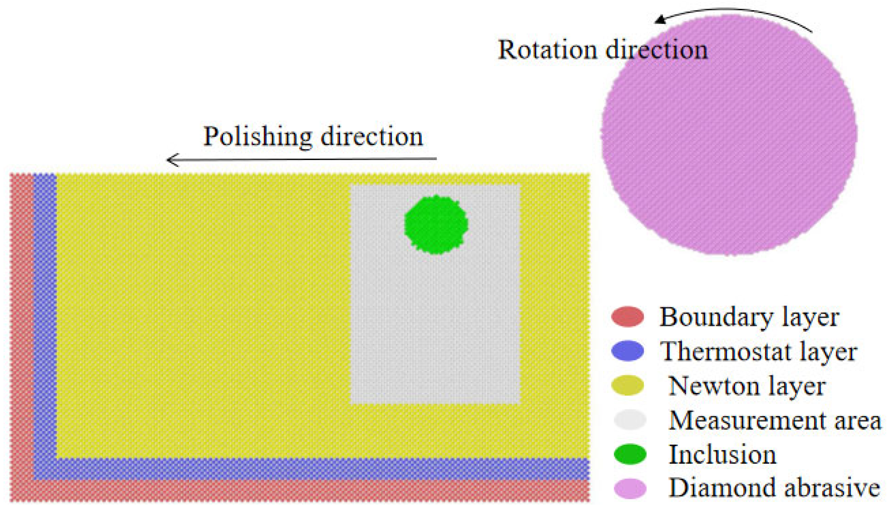
Figure 2.
Changes in temperature and potential energy.

Figure 3.
variation of force and friction coefficient.
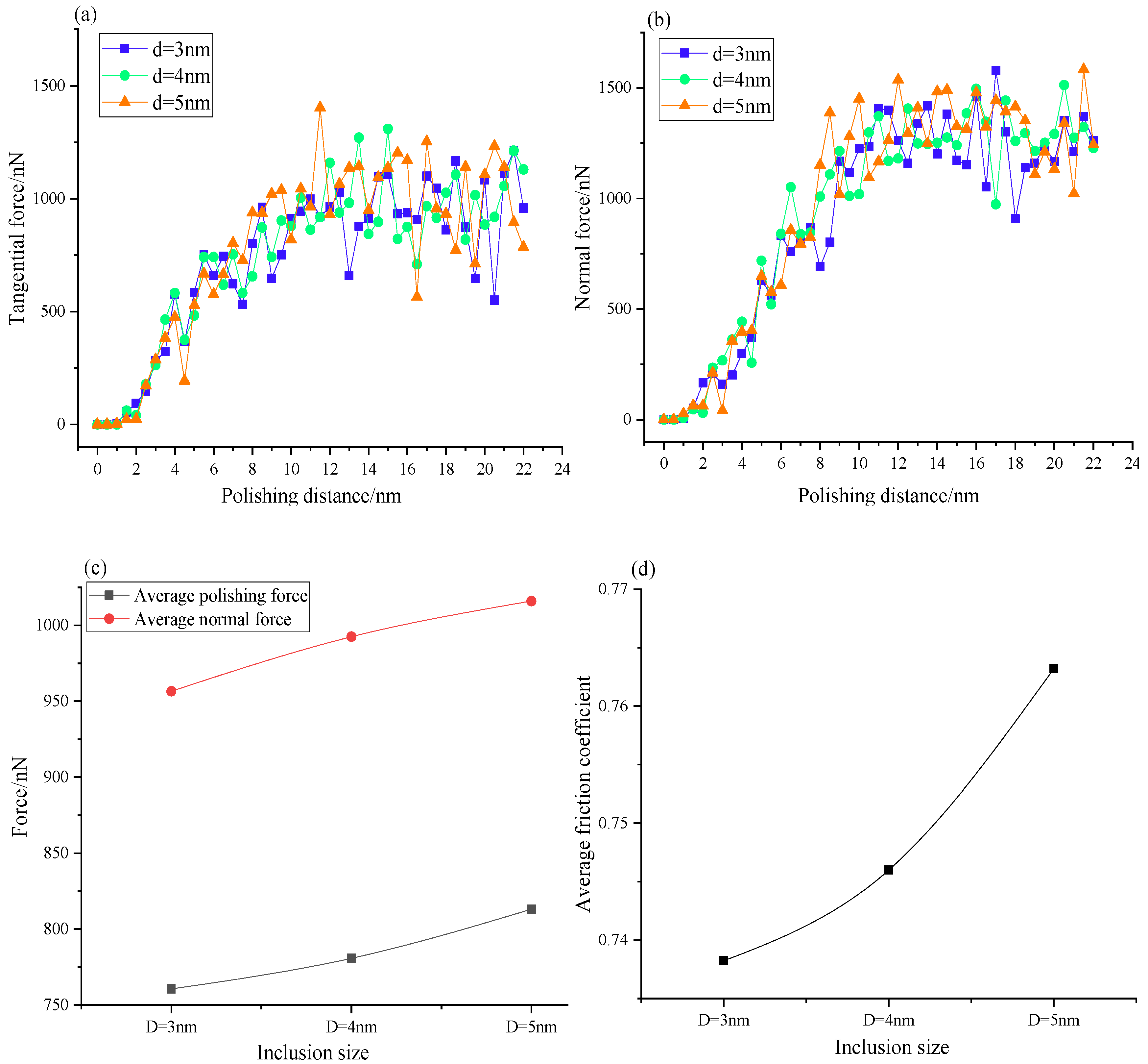
Figure 4.
Phase transition of silicon during contact loading.[37].
Figure 4.
Phase transition of silicon during contact loading.[37].
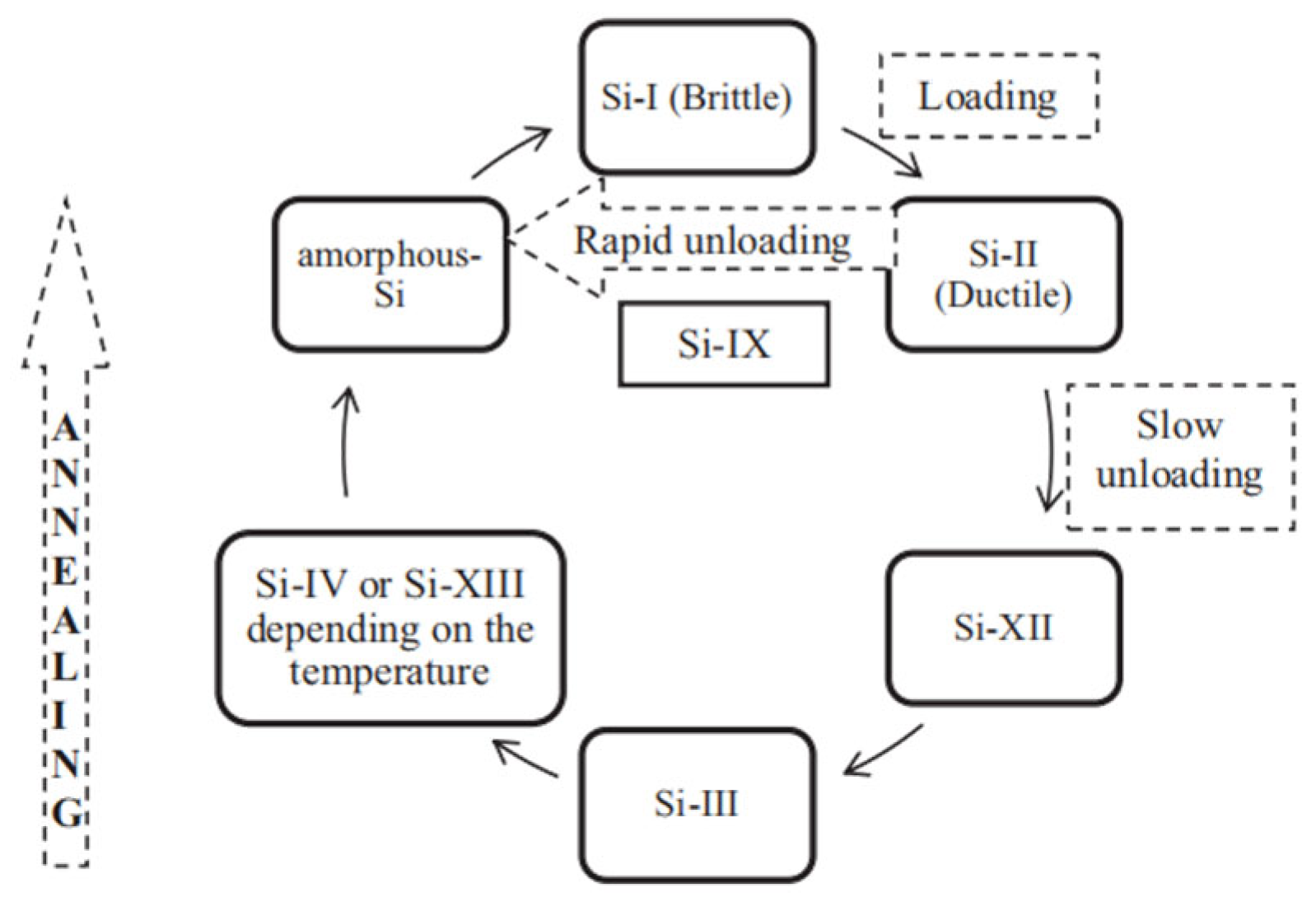
Figure 5.
The change in coordination number.
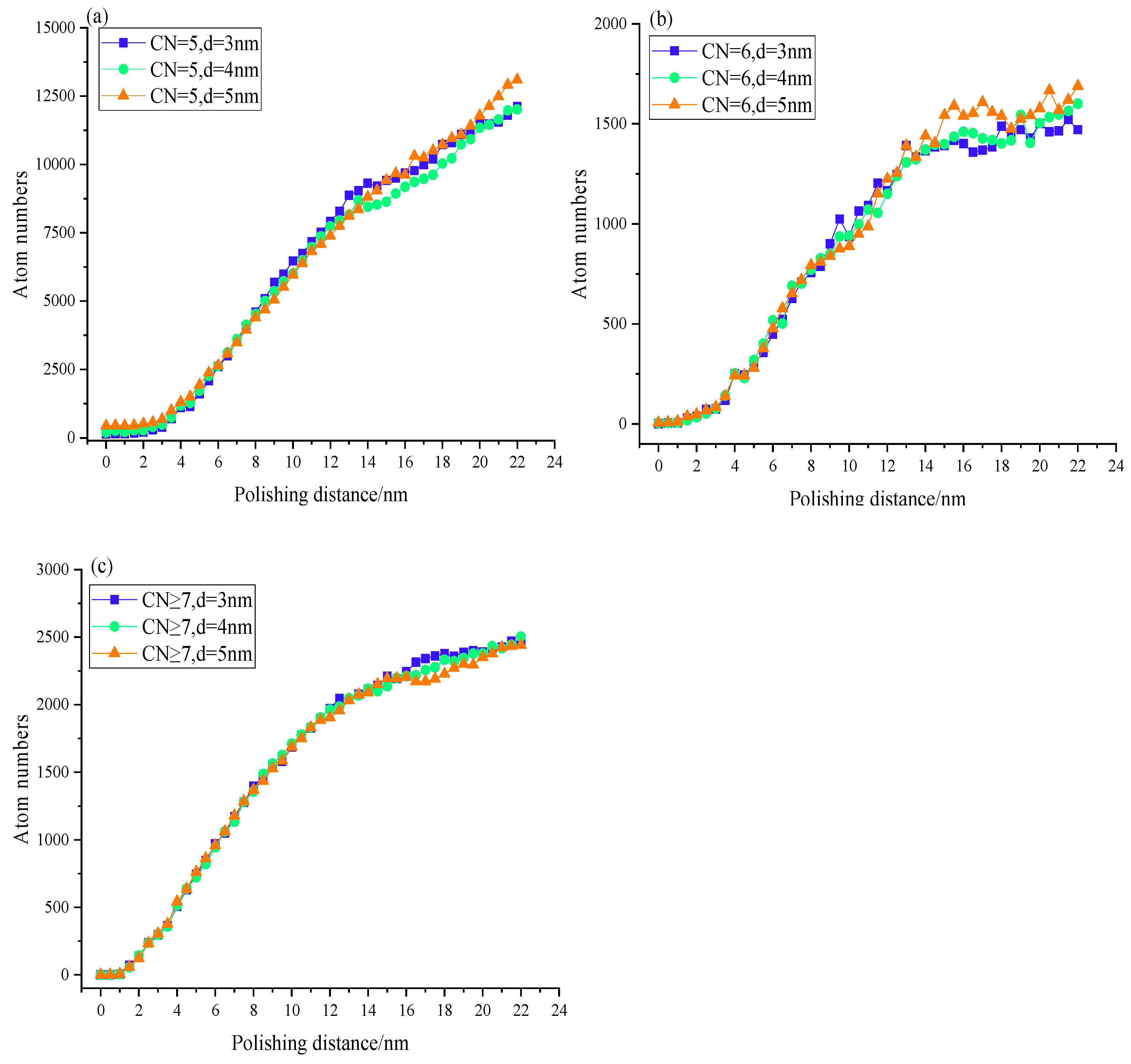
Figure 6.
Evolution of coordination number inclusion with a diameter of 3 nm.
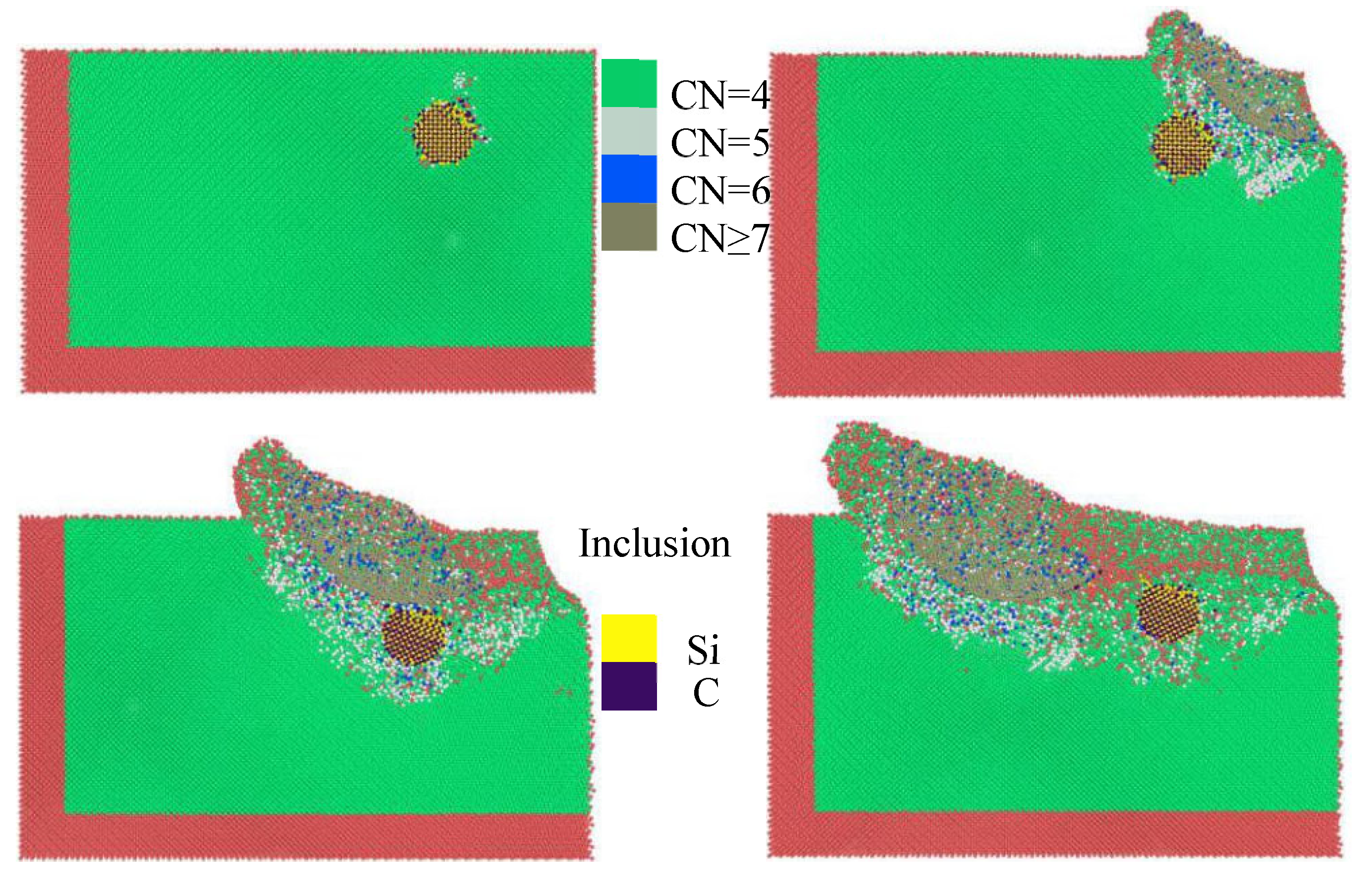
Figure 7.
Evolution of coordination number inclusion a diameter of 5nm.
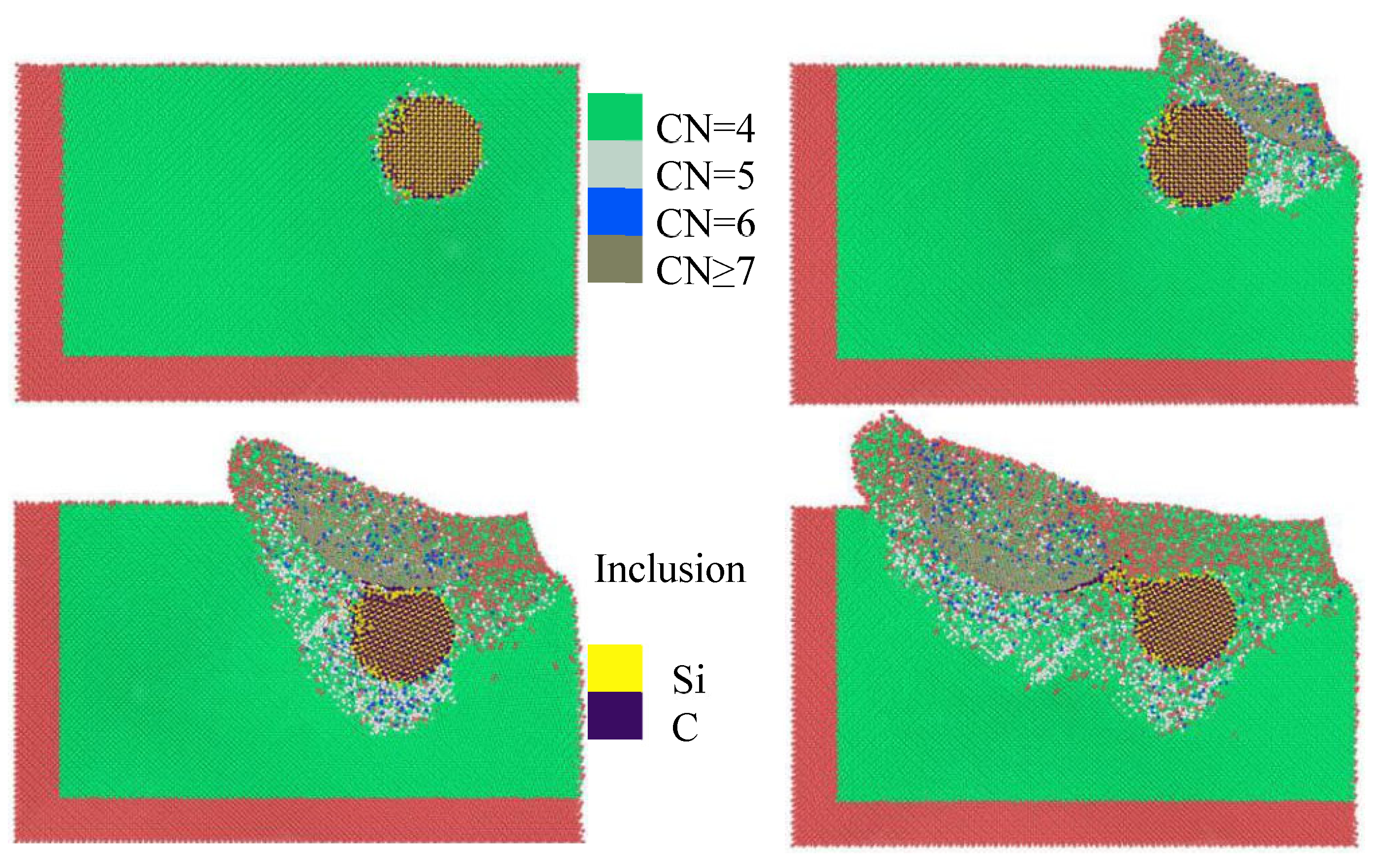
Figure 8.
Damage depth of subsurface with different inclusion diameters.
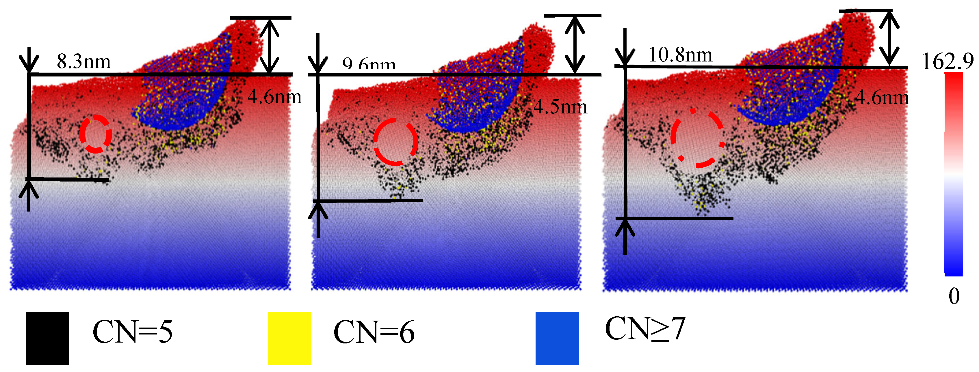
Figure 9.
Final state and proportion of different types of diamond structure analysis.
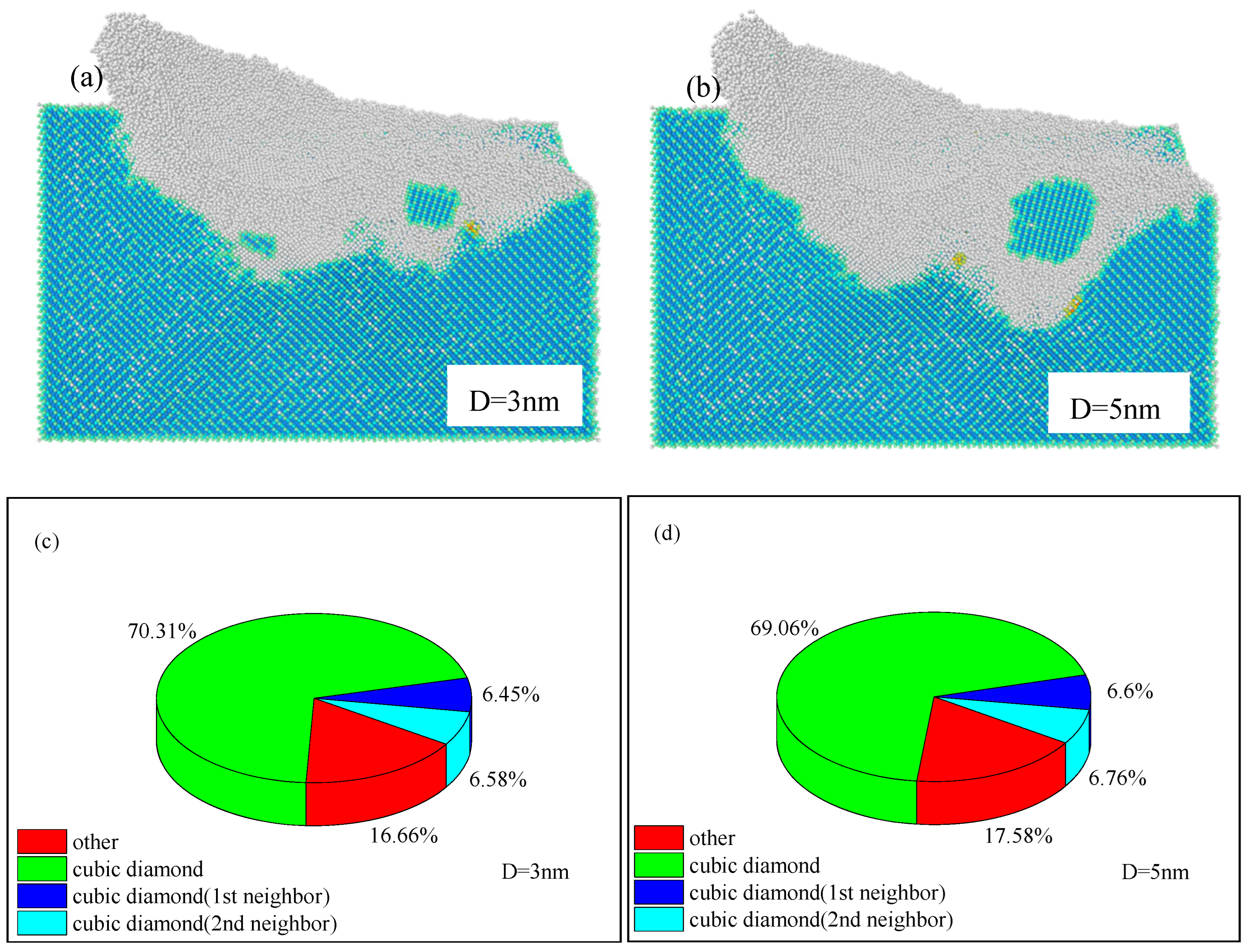
Figure 10.
variation of dislocation number and length.
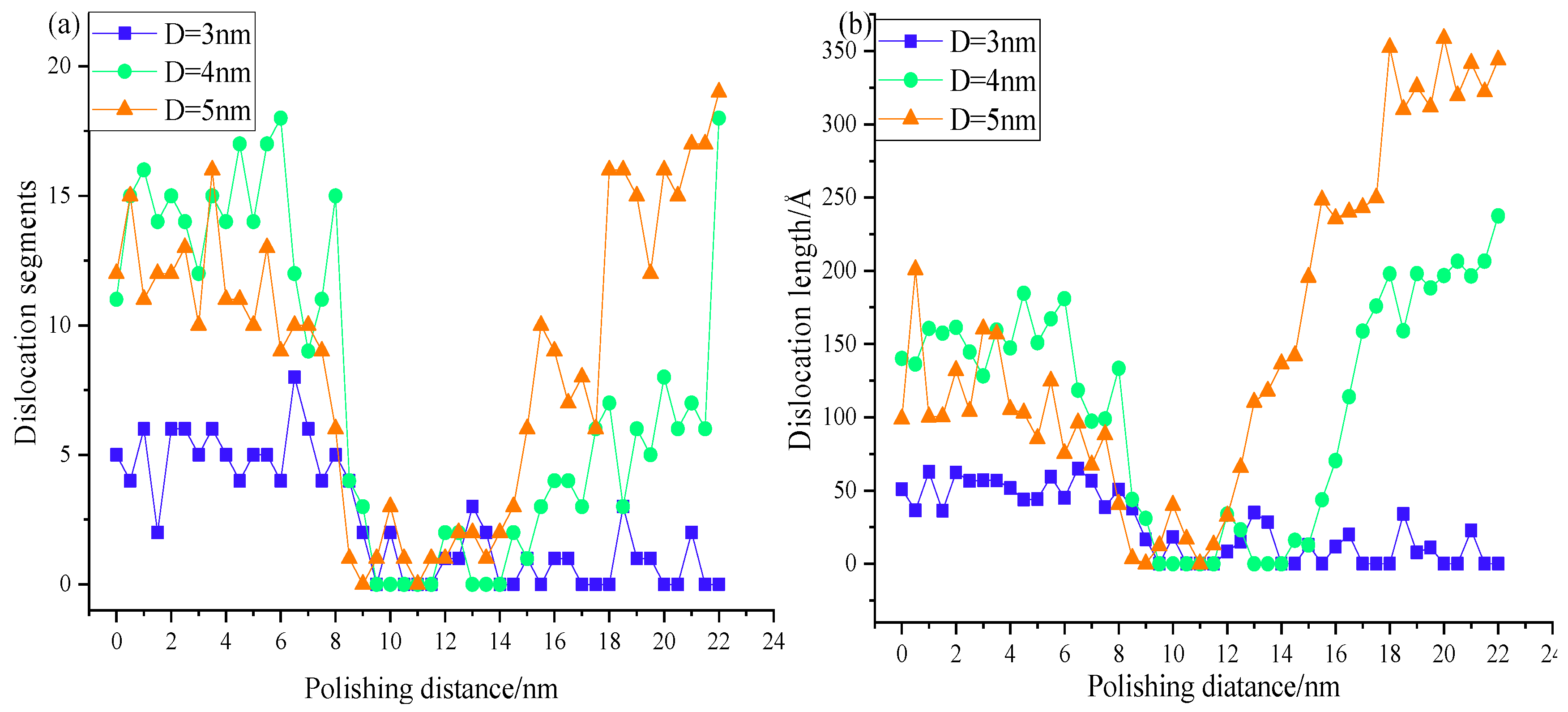
Figure 11.
evolution of dislocation with a diameter of 3 nm.
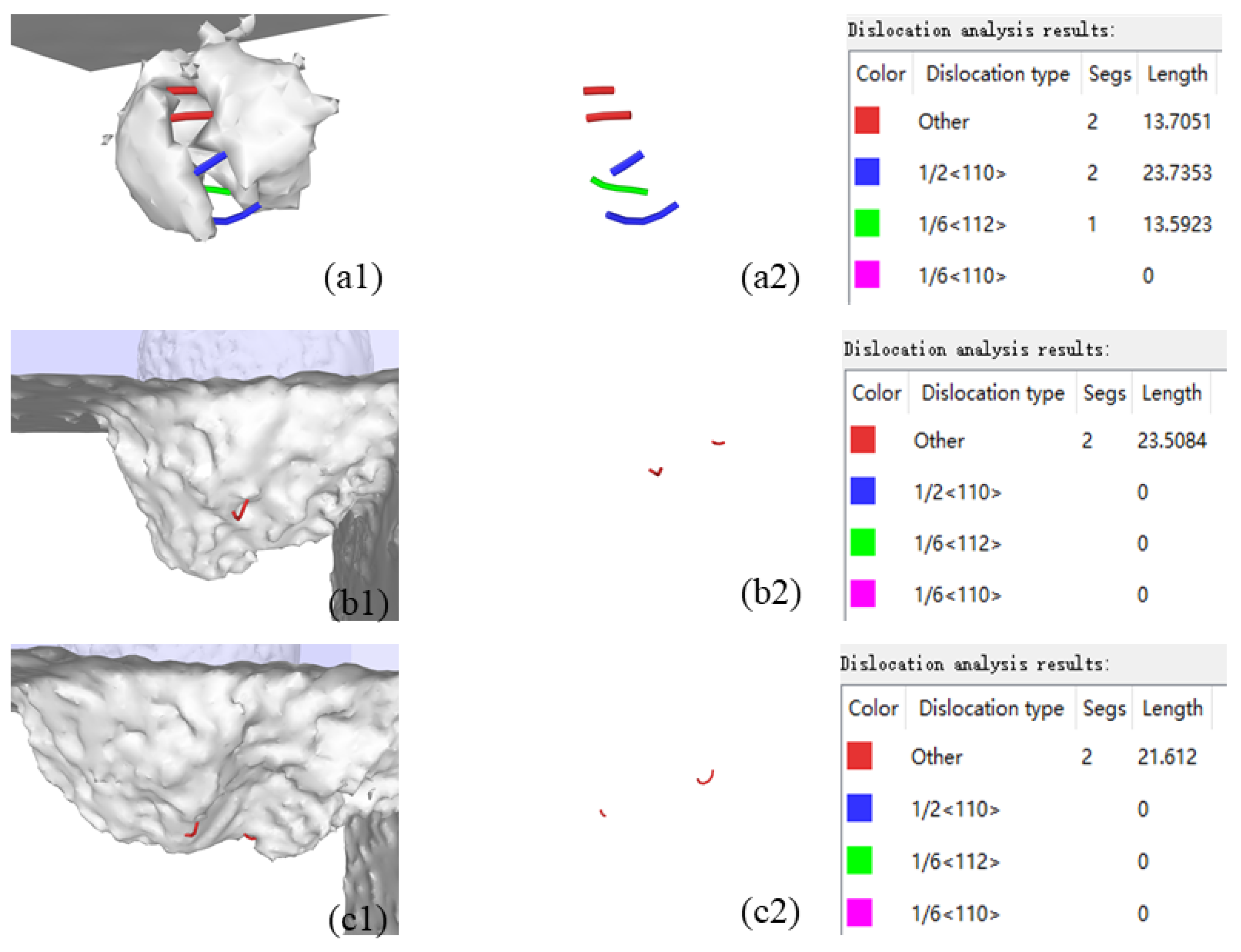
Figure 12.
Evolution of dislocation with a diameter of 4nm.
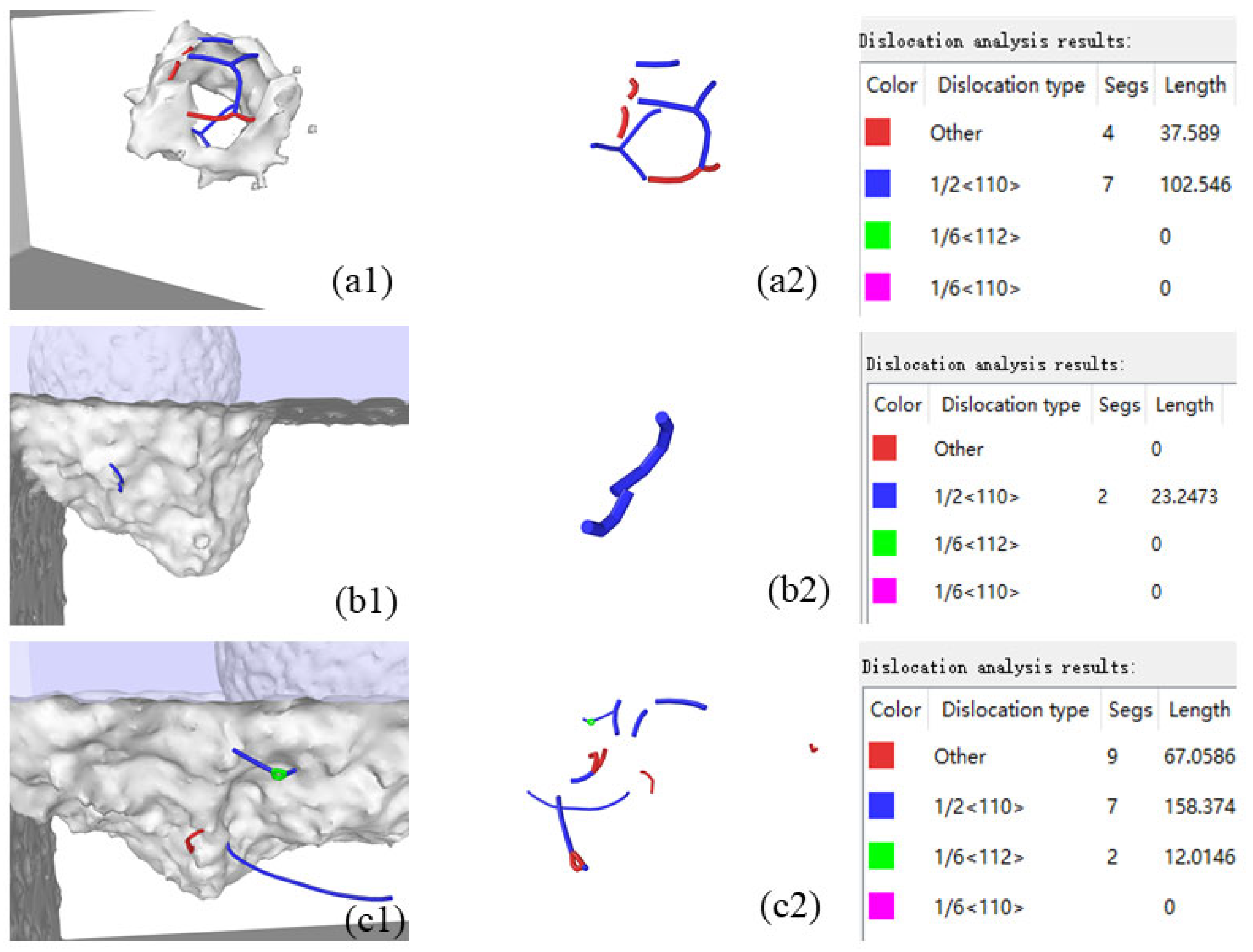
Figure 13.
Evolution of dislocations at a 5 nm in diameter.
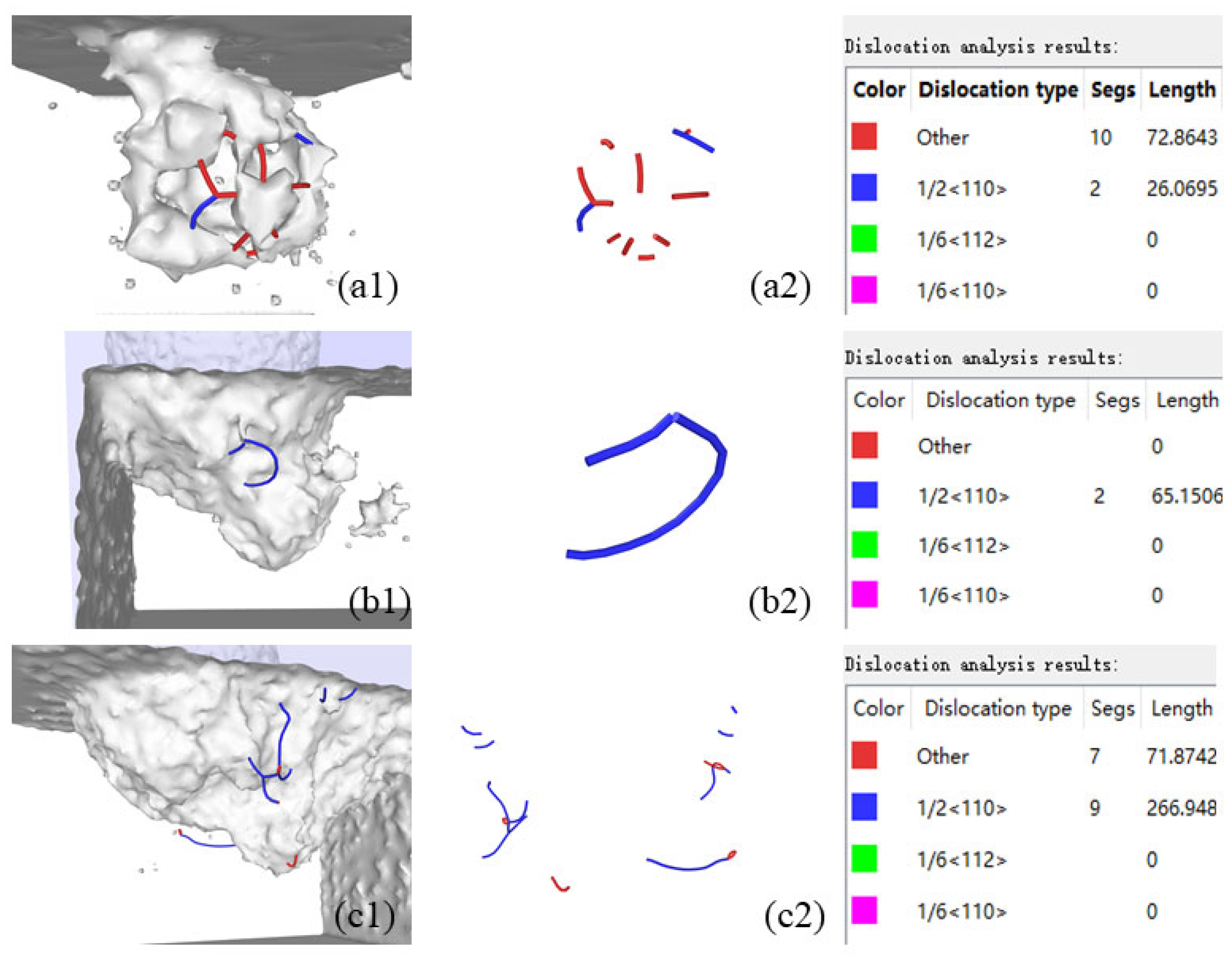

Table 1.
Parameters of molecular dynamics simulation.
| Configuration | Parameter |
| Wafer | Monocrystalline Silicon |
| Abrasive particle | Diamond particle |
| Wafer dimensions | 50a×30a×30a (a=5.43Å) |
| Workpiece surface | [-1 0 0] on (0 0 1) surface |
| Abrasive atomic number | 159484 |
| Workpiece atomic number | 365494 |
| Polishing velocity | Moving velocity=200m/s |
| Self-rotation velocity=100m/s | |
| Time step | 1fs |
| System temperature | 293K |
| Diameter of particle | 12nm |
| Diameter of inclusion | 3, 4, 5nm |
| Inclusion | 3C-SiC |
| Ensemble | NVE |
| Polishing depth | 4nm |
| Moving distance | 22nm |
Table 2.
Potential function used in the MD simulations.
| Properties | Potential function |
| Workpiece and inclusion (Si-C) | Tersoff:D=0.20;S=1.847; ro=1.79 |
| Workpiece and inclusion (Si-Si) | Tersoff:D=0.14;S=1.842; ro=2.232 |
| Si atoms and diamond atoms (Si-C) | Morse:D=0.435;α=4.6487; ro=1.9475 |
| C atoms and diamond atoms (C-C) | Morse:D=2.423;α=2.555; ro=2.522 |
| Diamond atoms (C-C) | none |
Disclaimer/Publisher’s Note: The statements, opinions and data contained in all publications are solely those of the individual author(s) and contributor(s) and not of MDPI and/or the editor(s). MDPI and/or the editor(s) disclaim responsibility for any injury to people or property resulting from any ideas, methods, instructions or products referred to in the content. |
© 2025 by the authors. Licensee MDPI, Basel, Switzerland. This article is an open access article distributed under the terms and conditions of the Creative Commons Attribution (CC BY) license (http://creativecommons.org/licenses/by/4.0/).
Copyright: This open access article is published under a Creative Commons CC BY 4.0 license, which permit the free download, distribution, and reuse, provided that the author and preprint are cited in any reuse.


