Submitted:
01 October 2025
Posted:
01 October 2025
You are already at the latest version
Abstract
Harmonic-assisted phase amplification was investigated in a 300-mm-thick Nd:GdVO4 laser with coated end mirrors in the self-mixing interference scheme. The key event is the self-induced hybrid skew cosh Gaussian-type transverse mode oscillation in a thin-slice solid-state laser with wide-aperture laser-diode pumping. The present hybrid skew-chG mode was proved to be formed by the locking of nearly frequency-degenerate TEM00 and annular fields. The resultant modal-interference-induced gain modulation at the beat frequency between the two modal fields, which is far above the relaxation oscillation frequency, increased experimental self-mixing modulation bandwidth accordingly. Fifty-fold phase amplification was achieved in a strong optical feedback regime.
Keywords:
laser cavity resonators
; laser modes
; laser feedback
; laser velocimetry
; acousto-optic effects
; optical variables control
; optical variables measurement
1. Introduction
Kogelnik and Li published a monumental work on optical resonators based on the principles of optics in which they found that Hermite-Gaussian modes form in Fabry-Perot optical cavities as stable orthogonal transverse eigenmodes [1]. Additionally, Fabry-Perot microcavities, such as vertical-cavity surface-emitting laser diodes (VCSELs) and thin-slice solid-state lasers with coated end mirrors (abbreviated as TS3Ls), have been studied in a different context related to the spatiotemporal dynamics of transverse modes in Fabry-Perot microcavities. The Fresnel number of a thin-platelet TS3L cavity, NF = a2/(a: aperture radius, : optical cavity length, : lasing wavelength), is on the order of 102–103 larger than those of conventional cavities. Large-cavity Fresnel numbers enable lasing in a variety of transverse modes depending on the shape and spot size of the pump beam, i.e., by controlling the gain and thermally induced refractive index confinements of the lasing transverse modes as well as the actuated saturation type of optical nonlinearities inherent to TS3Ls. These forms of lasing include vortex arrays originating from a higher-order Ince-Gauss mode in elliptical coordinates, rectangular-type vortex arrays born from Hermite-Gauss modes in a 300-μm-thick LiNdP4O12 (LNP) laser with shaped laser-diode pumping [2], Laguerre-Gauss modes born from Ince-Gauss and Hermite-Gauss modes in a 1-mm-thick c-cut Nd:GdVO4 laser with wide-aperture laser-diode pumping [3] as well as modified Gaussian mode featuring pump-dependent “emerge-emerge process” of an annular field around the Hermite-Gauss mode [4].
In addition to a variety of pump-profile dependent lasing transverse mode formations, the self-mixing interference effect in TS3Ls between the lasing field, and the weak optical field from the target, , has been recognized as being a simple self-aligned, cost-effective optical sensing technique that does not use sophisticated optical interferometers and highly sensitive electronics, in which a laser acts as a high-efficiency mixer oscillator and a shot-noise-limited quantum detector [5]. The effective self-mixing modulation index is given by me = 2hK (h= /: amplitude feedback ratio, K = τ/τp: fluorescence-to-photon lifetime ratio) and the power spectral intensity of the detected electrical self-mixing signal is proportional to me2 [6,7,8]. TS3Ls with large lifetime ratios have been used to make versatile self-mixing metrology systems with extreme sensitivity [9,10,11].
On the other hand, the dynamic changes in many physical quantities, including displacement, temperature, and electrical and magnetic fields, can be transduced into changes in the relative phase between light fields or wave functions [12,13,14]. Therefore, most high-precision measurement tasks can be converted into the measurement of the phase change in a specific physical process, and methods to amplify the phase are highly important for phase measurement resolution enhancement in metrology operations. Harmonics-assisted phase optical phase amplification has been demonstrated, where the relative phase difference between two polarization modes in a polarized interferometer is amplified coherently four times with cascaded second-harmonic generation processes [15]. Most recently, a new phase amplification method has been studied that is based on the feedback-induced intracavity harmonic generation effect in a laser frequency-shifted feedback interferometer (FIHG effect) employing a LD-pumped thin-slice Nd:YVO4 laser. It was reported that the relative phase change between the two arms of the interferometer is amplified by 11 times by the FIHG effect without assistance of any external harmonic generation [16], which exceeds the maximum amplification of around 10 that has been experimentally obtained using a many-body entangled state [15,17].
On the basis of the above background, we examined ways of forming the lasing transverse mode inherent to TS3Ls with wide-aperture LD pumping and their application to phase amplification by self-mixing modulation. In this paper, we describe skew-chG mode oscillations in a 300-m-thick Nd:GdVO4 laser with wide-aperture LD pumping for the first time, where an annular transverse field surrounding the central Gaussian field appears with increasing pump power by controlling the pump-beam diameter. A physical interpretation for the appearance of the annular lasing field is given in terms of the additional gain that appears around the preceding TEM00 mode resulting from the transverse spatial hole burning effect of population inversions with wide-aperture pumping. The phase locking of nearly frequency- degenerate TEM00 and annular fields is shown to form hybrid type of skew-chG mode. Harmonic-assisted phase amplifications in such a hybrid skew-chG laser operation were demonstrated in the self-mixing laser Doppler velocimetry scheme as well as in the frequency-shifted optical feedback scheme using acousto-optic modulators (AOMs).
With increasing the optical feedback ratio, the coherent modal beat wave generated through the modal interference of nearly frequency degenerate transverse modes suffered an enhanced self-mixing modulation by frequency-shifted feedback light. The resultant frequency bandwidth of harmonic-assisted phase amplifications increased far above the relaxation oscillation frequency. Fifty-fold phase amplification was achieved in the strong feedback regime.
2. Self-Induced Skew-Cosh Gaussian Mode Laser Oscillation
2.1. Wide-Aperture LD Pumping and Slope Efficiency
The experimental setup with a Nd:GdVO4 laser is shown in Figure 1. A nearly collimated lasing beam from a laser diode (wavelength: 808 nm) was passed through an anamorphic prism pair to transform the elliptical beam into a circular one that was focused onto a 300-μm-thick laser crystal. One end surface was coated to be transmissive at the laser-diode pump wavelength of lp = 808 nm and highly reflective (R1 = 99.9%) at the lasing wavelength of ll = 1063 nm. The other surface was coated to be R2 = 99% at 1063 nm. Linearly polarized single longitudinal-mode emissions along the b-axis were observed in the entire pump power region, reflecting the fluorescence anisotropy. The pump-beam spot size, wp, was changed by shifting the laser crystal along the z-axis, as depicted in Figure 1.
The pump spot size, wp, increased as the laser crystal was shifted away from the pump-beam focus along the z-axis (i.e., z > 0). The pump spot size varied from wp = 20 mm (z = 0) to 85 mm (z = 2.5 mm). A pure TEM00 mode oscillation was obtained at the threshold pump power, Pth = 20 mW, at wp = 20 mm (z = 0), where the lasing spot size was measured to be wo = 30 mm and the slope efficiency was hs = 24% as depicted by black in the input-output characteristics in Figure 1. As wp increased, the threshold pump power gradually increased and the resultant lasing transverse mode exhibited a structural change in the near-field pattern. The slope efficiency increased to hs = 40% regardless of the increase in threshold pump power to Pth = 56 mW for wide-aperture pumping at wp = 70 mm as depicted by red in the input-output characteristics due to the increase in the lasing mode volume as will be discussed in the following Section 2 and Section 3.
The harmonics-assisted phase amplification was examined in two ways. One was self-mixing laser Doppler velocimetry by focusing the output beam onto a rotating Al cylinder by a 15-cm focal-length lens placed 30 cm apart from the laser and the cylinder surface, where the laser was modulated at the Doppler-shift frequency, fD = v/ (v: velocity along the laser axis). The other mixing modulation was performed using a pair of PbMoO4 acoustic-optic modulators (AOMs; center frequency = 80 MHz) whose self-mixing modulation frequency is given by fM = 2(fm,1 - fm,2) depicted in Figure 1.
2.2. Lasing Beam Profiles
Near- and far-field lasing patterns were measured using a PbS phototube (Hamamatsu C1000) followed by a TV monitor and an intensity profiler. Typical results are shown in Figure 2 with increasing the pump power for a wide-aperture pumping of wp = 70 mm.
As can be seen in the movie, the pure TEM00 mode appearing near the threshold pump power exhibited successive structural changes and the annular part increased with increasing pump power. It is noteworthy that the near-field intensity patterns in the present laser with wide-aperture pumping are approximated by the following skew cosh Gaussian (skew-chG) mode profile, where :
while the far-field patterns exhibited super-Gaussian-type intensity distributions of order p:
Here, n is the order of skewness, and s and bw are the skewness parameter and the beam width. Radial intensity profiles and fitting curves are shown on the lower row of Figure 2 by red, where the coefficient of determination is as high as R2 0.98.
2.3. Transverse Spatial Hole-Burning of Population Inversions
The spot sizes at the input and output mirrors, w1 and w2, and the effective focal length of the thermal lens, fT, are given by [18]
Here, l is the effective thickness of the thermally induced lens, while A is the heat generated per unit volume and time, KT is the thermal conductivity, dn/dT is the thermal-optic coefficient of the refractive index, a is the coefficient of thermal expansion, and n0 is the refractive index of Nd:GdVO4. Here, since A increased as the pump power increased, the focal length was considered to decrease and the lasing beam spot size decreased accordingly.
The TEM00 spot sizes, w1,2, were calculated using Eqs. (3) and (4) and the thermal constants of Nd:GdVO4, KT = 11.7W/mK, dn/dT = 4.7x10⁻⁶/K, a = 1.5x10⁻⁶/K and n0 =1.972. They are plotted in Figure 3, together with the average pump beam spot size, wp = 70 mm. This figure indicates that wide-aperture pumping, i.e., wp > wo, is established for the case shown in Figure 2. In fact, the pure TEM00 lasing mode spot sizes at the crystal near the threshold pump power is estimated to be 45~50 µm and agrees with the lasing spot size, wo = 47µm, which was measured by the intensity profiler connected to the PbS phototube.
Next, let us consider the transverse spatial hole-burning effect of population inversions. The pump rate of excited atoms and decreasing rate of excited atoms by lasing photons through stimulated emission are given by spIp/hnp and seIcir/hno, respectively. Here, IP and Icir denote the pump light and circulating lasing intensities within the cavity, np and no are pump and lasing light frequencies, whereas se and sp are respectively emission and absorption cross sections.
Assuming wp = 70 mm, wo = 47 mm, and spectroscopic data for Nd:GdVO4: t = 90 ms, se = 7.610-19 cm2 and sp = 4.9x10⁻¹⁹ cm2, calculated radial profiles related to the lasing intensity and population inversions are shown in Figure 4(a), (b) and (c), where
(a) Pump-dependent intracavity circulating photon emission rate of the proceeding TEM00 mode, which is given by Icir = Is (I/Ith -1) o/(pwo2)ln(-R2), where Is = hno/set is the emission saturation intensity, Ith is the threshold pump intensity and Po is TEM00 pump-dependent output power component as estimated from the input-output characteristics in Figure 1 and the weighting number for a TEM00 field.
(b) Remaining atom excitation rate (i.e., remaining population inversions) in the presence of the preceding TEM00 mode for various pump intensities.
(c) Effective atom excitation rate for the annular region defined as the hole depth, 10log(Nr/NTEM), where Nr is the remaining atom excitation rate in Figure 4(b).
As the pump power increases, depletion of the population inversion (i.e., transverse spatial hole burning) takes place. Here, the spatial integral of the remaining population in version, V = dv, was found to coincide with the threshold value for Icir = 0 for all pump powers within 3% error. This strongly implies that the population inversion density is kept at the threshold value under the lasing condition for the preceding TEM00 mode obeying laser theory. While, the remaining population inversion shown in Figure 4(b) is expected to give an additional effective gain for annular mode to coexist with TEM00 mode with increasing the pump power so that almost all the population inversion contributes to lasing by wide-aperture pumping. The effective excitation for the annular mode gain spreads outward featuring a skewness with increasing pump power as shown in Figure 4(c) for the wide-aperture pumping, wp > wo, and a skewed annular-type of amplification is expected for lasing fields around the preceding TEM00 mode via the gain guiding effect [19]. Here, the lasing mode volume increases and the higher slope efficiency is brought about in comparison with the TEM00 mode as shown in Figure 1.
On the other hand, the population-inversion-dependent refractive index variation, , can be expressed as [20,21]
Here, fL = (n02 + 2)/3 is the Lorentz local-field correction factor, Ne denotes the excited-state ion population and = ae - ag is the difference in polarizability of active ions in the metastable and ground states. Usually, Ne is, to first order, proportional to the pump intensity, Ne ≈ NT(Ip/Is,a), where NT is the terminal-state ion population, Is,a = hc/λpσpτ is the absorption saturation intensity at the excitation wavelength, λp. Since Ne is proportional to IP, Eq. (5) can be written in terms of the pump-intensity-dependent refractive index change, n = n2’IP: [20,21]
For Nd:GdVO4 crystals, the value of is unknown, but the annular emission is expected to join with the pure Gaussian emission (which obeys Eqs. (3)-(4)) because of the pronounced modal gain G () resulting from gain guiding and refractive index confinement with wide-aperture pumping, i.e. wp wo, in accordance with Figure 4(c) and Eq. (6).
It should note that the near-field intensity profile observed at P =120 mW, which is fitted well by the skew-chG mode given by Eq. (1) with R2 = 0.988 in Figure 2(a), is theoretically reconstructed as shown in Figure 5(a) if we assume the phase locking of two nearly frequency-degenerate TEM00 and annular fields, namely Eg and Ea, in the form of Eg + irEa, where r is the weighting number for field amplitude and i implies the relative phase of p/2 [2], which will be discussed in the next Section. A skewed intensity profile reflecting the skewed gain profile in Figure 4(c) with respect to the gain peak is apparent for the annular mode. In fact, the peak gain determined from the amplitude ratio of two fields at P = 120mW shown in Figure 5(a) is 2.07dB and it coincides well with 1.94 dB evaluated from Figure 4(c). Theoretical reconstructions of modified skew-chG patterns for different pump powers in Figure 2 assuming the locking of TEM00 and annular modes are shown in Figure 5(b) and Figure 55(c), respectively. As for Figure 5(b) at P = 150mW, the peak gain is 5.3dB and it coincides with 5.6dB evaluated from Figure 4(c). Harmonics-assisted phase amplifications in the following section, which stems from the phase locking of two modes, was successfully achieved in the pump power region, 70 mWP160 mW.
3. Self-Mixing Mixing Modulation in Modified Skew Cosh Gaussian Mode Laser
3.1. Phase Amplification in Weak Feedback Regime
In this Section, we address the key issue in the nonlinear dynamics of such modified skew-chG mode lasers subjected to self-mixing interference modulations by employing two methods, self-mixing laser Doppler velocimetry and frequency-shifted feedback using acousto-optic modulators, as shown in Figure 1. Here, self-mixing interference metrology works through the intensity modulation effect of a laser due to interference between the lasing and feedback fields. In short, the self-mixing laser acts both as a mixer-oscillator and highly sensitive detector of the signal from the target. The resultant optical sensitivity has been shown to be enhanced in proportion to the square of the fluorescence-to-photon lifetime ratio, K = t/ tp, which reaches an order of 105 –106 in state-of-the art TS3Ls [6,7,8]. The photon lifetime in the present Nd:GdVO4 laser was determined by measuring the dependence of the relaxation oscillation on the excess pump rate: fRO = (1/2p), w = P/Pth, as shown in Figure 6(a). Assuming t = 90 ms, tp of 20 ps was attained, yielding K = 4.5x10⁶.
Self-mixing interference effects in the modified skew ch-G laser subjected to subharmonic modulations, fM = fRO/2, have been found to depend critically on the feedback ratio from the target. In the case of the self-mixing laser Doppler velocimetry scheme in Figure 1, the effective intensity feedback ratio from the same rotating Al cylinder for the pure TEM00 operation was estimated to be h = 83 dB from the correspondence between the experimental and numerically reproduced power spectral intensities of the Doppler signal at fD [22]. The basic idea of subharmonic resonance effect caused by the modulation at fM = fRO/2, which induced a quasi-period-2 modulation resemble to Figure 6(c), was reported in the self-mixing TS3L Doppler velocimetry scheme in 1979 [8].
By inserting a variable attenuator with a roundtrip attenuation of TA 9 dB in Figure 1, the deep period-2 modulation took place as shown in Figure 6(b). The similar periodic-2 modulation was achieved in the AOM scheme as shown in Figure 6(c) by controlling the feedback condition from the Al plate in Figure 1 similarly to the LDV scheme mentioned above. Power spectrum was obtained by averaging 100 power spectra measured at intervals of the update, 160μs, for both cases.
Period-2 pulsations inherent to phase amplification are considered to appear through coherent superposition of N harmonic waves. Harmonic waves up to N = 13 and 12 were obtained by filtering the original time series shown in the upper inset with a bandwidth of 100 kHz. The phases of the Nth-harmonic waves coincided with that of the fundamental wave every N periods. There are excellent phase correlations up to N = 13 and 12 in both self-mixing feedback schemes.
Figure 7(a) shows the original and reconstructed LDV signal, which is the summation of harmonic waves up to N = 13 in the self-mixing LVD scheme. The excellent amplitude and phase correlations with R2=0.997 are obvious as expected. The excellent correlation was also obtained for AOM feedback scheme.
These phase-synchronized waveforms shown in Figure 8a,b were theoretically reproduced by the following Eq. (7) derived from dynamic equation [16] as shown in Figure 8(a’,b’).
Here, DIN is the intensity modulation (i.e., AC component) of the N-th harmonic component, D is the relative phase change between the two arms in the self-mixing laser interferometer, is the initial fixed phase of the system, CN represents the intensity output coefficient of the N-th harmonic, which is related to the feedback induced gain and the cavity loss for harmonic waves.
Therefore, the observed phase-synchronization of all subharmonic waves with the fundamental wave is the direct experimental evidence supporting Tian and Tan’s assertion based on the analysis with the lock-in amplifier. They demodulated D through the lock-in amplifier and proved that the dependence on NΔφ instead of D allows us to achieve phase super-resolution measurement of D, because the phase oscillation is N times faster than the original phase change and the unwrapped phase change Δφu is linearly proportional to the optical path change ΔL as Δφu = N(2p/ll)ΔL [16]. They achieved phase amplification up to N = 11 harmonics by using a 0.75mm-thick Nd:YVO4 TS3L which was modulated at subharmonic resonance frequency, fM = fRO/22MHz. In our case, and the maximum deviation from the perfect phase-synchronization depicted in the lower part of Figure 8 was evaluated to be 1% for both feedback schemes.
We performed experiments at fM = fRO/2 = 0.483MHz by decreasing the pump power to P62mW. Results are shown in Figure 9, featuring (a) period-2 waveform, (b) corresponding power spectrum and (c) Poincare map. The phase synchronization up to N = 19 was achieved with SNR 5dB at 9.18 MHz.
3.2. Phase Amplification in Intermediate Feedback Regime
The additional gain shown in Figure 4(c) as well as pump-intensity-dependent refractive index given by Eq. (6), which are determined by the thermal lens effect, i.e., Eqs. (3)-(4), excite the annular mode around preceding TEM00 mode. The refractive index (equivalently, laser cavity length) for the annular mode increases with increasing the pump power and the lasing frequency is expected to be shifted slightly from that of the central TEM00 mode accordingly. With increasing a feedback ratio, the modal output waveform was strongly modified, while the self-mixing total output waveform exhibited the period-2 type of waveform, where self-mixing modulation originating from the two fields in Figure 5(b) in the skew-chG profile are coupled nonlinearly as will be discussed hereafter.
An example output waveform obtained by the self-mixing LDV scheme and the corresponding power spectrum obtained at fM = fRO/2=2MHz are shown in Figure 10(a), at a round-trip attenuation of TA 6 dB, i.e., intermediated feedback regime. The power spectrum has a secondary peak around 24 MHz whose envelope has a Gaussian profile as will be discussed later again in Section IV. The enlarged peculiar total output waveform is shown at the top of Figure 10(b), where the higher frequency component seems to be superimposed on the period-2 pulsation. To clarify such a higher frequency component, total output waveforms filtered below and above 17 MHz are shown in the middle of Figure 10(b), where the total output in the lower-frequency band, IL(t), exhibits a period-2 like periodic waveform reflecting the self-mixing modulation due to the coexisting transverse modes, whereas the total output in the higher-frequency band exhibits periodic oscillations at DnB = 24 MHz, whose envelope is modulated at fM, as shown by the blue waveform.
In the present experiment, the gain (stimulated emission) modulation is considered to be brought about at a beat frequency, DnB, through modal interference of phase-locked transverse modal fields corresponding to Figure 5 in the form of , where and are the preceding TEM00 field and the self-excited disturbing annular field, where B is the stimulated emission coefficient and N0 is the population inversion density. Instead of the complete transverse mode locking, the present “hybrid” skew ch-G lasing pattern is formed of nearly frequency-degenerated TEM00 and annular fields with the fixed relative phase of p/2 as discussed in 2.3, where the laser is modulated by coherent higher-frequency beat note at DnB >>fM. Then, the coherent beat note might suffer the self-mixing modulation at fM << DnB as well with increasing the feedback ratio. As a result, the power spectral components separated by fM are considered to arises around DnB and forms the higher-frequency band, where the harmonic resonance of DnB/ fM = 12, is established among the coexisting modal fields.
To clarify the interplay between these frequency bands, we carried out statistical analyses on total output waveforms belonging to the lower- and higher-frequency bands, i.e., IL(t) and IH(t), based on the observable quantity of intensity circulation given by [23,24]
The calculated intensity circulation is shown in the bottom plot of Figure 10(b). Here, it can be seen that IH(t) and IL,H (t) are correlated and IH(t) exhibits peaks in accordance with the intensity transfer from the lower to higher-frequency band, i.e., IL,H (t) > 0, as depicted by the blue upper arrow. This implies that the intensity transfer occurs from the lower to the higher band just after the strong peak of lower-frequency band indicated by the dashed line appears in IL(t) and the total intensity IH(t) reaches the maximum value within the periodic bursts at DnB.
Next, we examined the phase relationships among coexisting periodic waveforms of different harmonics within the lower- and higher-frequency bands in detail. The phases of the N-th harmonic waves in the higher-frequency band shown in Figure 11(a) are synchronized as well obeying Eq. (7). While, harmonics belonging to the higher-frequency band exhibited antiphase dynamics [25] against harmonics in the lower-frequency band, as shown by red dashed lines in Figure 11b,c, which parallel the middle inset of Figure 10(b), where only the fundamental wave at 2MHz in the low-frequency band is shown by red waveform for brevity.
After quite a short time delay depicted in Figure 11(b), the phase synchronization is established among harmonic waves in the higher-frequency band as indicated by the light blue arrows in the same way as Figure 10(b). In other words, the gain transfer from the lower to higher frequency band corresponding to the intensity transfer, as depicted by the blue arrows in the bottom of Figure 10(b), triggers the phase synchronization among all the harmonics in the higher-frequency band after a slight time delay on the order of 1/(2DnB). Consequently, the harmonic waves in both frequency bands obey Eq. (7) via a slight time delay indicating the subharmonic resonance of fM = DnB/12 in this case.
3.3. Phase Amplification in Strong Feedback Regime
When the feedback was increased further, TA3dB self-mixing signals exhibited more complicated behavior, featuring low-frequency envelope modulations. An example result obtained for fM = fRO/2=2MHz in the AOM feedback scheme is shown in Figure 13.
Here, the coherent beat frequency DnB between nearly frequency-degenerate transverse modes, TEM00 and outer ring, was shifted downward to 20 MHz and its harmonic peak appears at 40 MHz accordingly in the power spectrum. Despite such a nonlinear effect associated with increased feedback, harmonics-assisted phase amplifications up to N = 30 were achieved as shown in Figure 13(c).
Finally, let us show a fifty-fold phase amplification observed by removing VA in LDV scheme. Results are shown in Figure 14, where the pump power was decreased to P = 75 mW and the modulation frequency was set as fM = fRO/2 = 1 MHz. In this case, the lasing profile approached TEM00 as shown in Figure 2 and the second peak DnB was shifted downward, where harmonics up to 3DnB38 MHz appeared. The phase amplification up to N = 50 and essentially the same nonlinear dynamics as Figure 10, Figure 11, Figure 12 and Figure 13 were observed.
The correlation between original and reconstructed signal was found to be lowered as compared with that in the week feedback regime shown in Figure 7, however, the coefficient of determination was confirmed to be kept R2 > 0.93 even in the strong feedback regime by repeated experiments.
Finally in this section, it should be noted that the power spectrum in the strong feedback regime extends far above the relaxation oscillation frequency, fRO, in our skew cosh Gaussian laser system subjected to self-mixing modulation at fM = fD/2 contrary to the usual modulation dynamics, where frequency components decrease rapidly above the relaxation oscillation frequency due to the characteristic of laser in weak-feedback regime [26].
4. Statistical Properties of Collective Dynamics in Lower- and Higher-Frequency Bands
The small-signal modulation bandwidth beyond the relaxation oscillation frequency was studied in the context of a monolithic twin-ridge laterally coupled diode laser, where single- and double-lobed lasing modes coexist with split lasing frequencies [27]. The study experimentally showed that these modes exhibit mode locking and a lateral coupling resonance frequency arises above the relaxation oscillation frequency, similarly to our hybrid skew-chG mode operation involving two transverse lasing fields.
The significant dependence of the self-mixing subharmonic modulation effect on the feedback coefficient in the skew ch-G mode laser described in Section 3 can be interpreted in terms of the lateral coupling of Gaussian and annular fields within the laser. An example intensity power spectrum in the free-running condition, which follows the predictions of small signal analysis over a wide frequency range beyond the relaxation oscillation frequency [28], is shown in Figure 15(a).
The power spectrum in skew ch-G operation under the free-running condition shown in Figure 15 is fitted by a Lorentzian profile in the lower frequency band and a Gaussian profile in the higher frequency band. This spectral nature seems to be inherited to the harmonics-assisted phase amplification in the intermediate feedback regime, as shown in Figure 10(a), where the power spectral intensity of harmonics in the lower frequency band obeys a Lorentzian distribution while that in the higher frequency band follows a Gaussian distribution as indicated in Figure 15(b)-(c).
The peak forming the higher-frequency band might be directly related to the lateral-coupling resonance frequency DnB around the coherent beat frequency between the TEM00 and annular modal fields. Indeed, the broad Gaussian peak around DnB decreased in intensity when the pump power was decreased such that the lasing pattern approached the pure TEM00 mode oscillation.
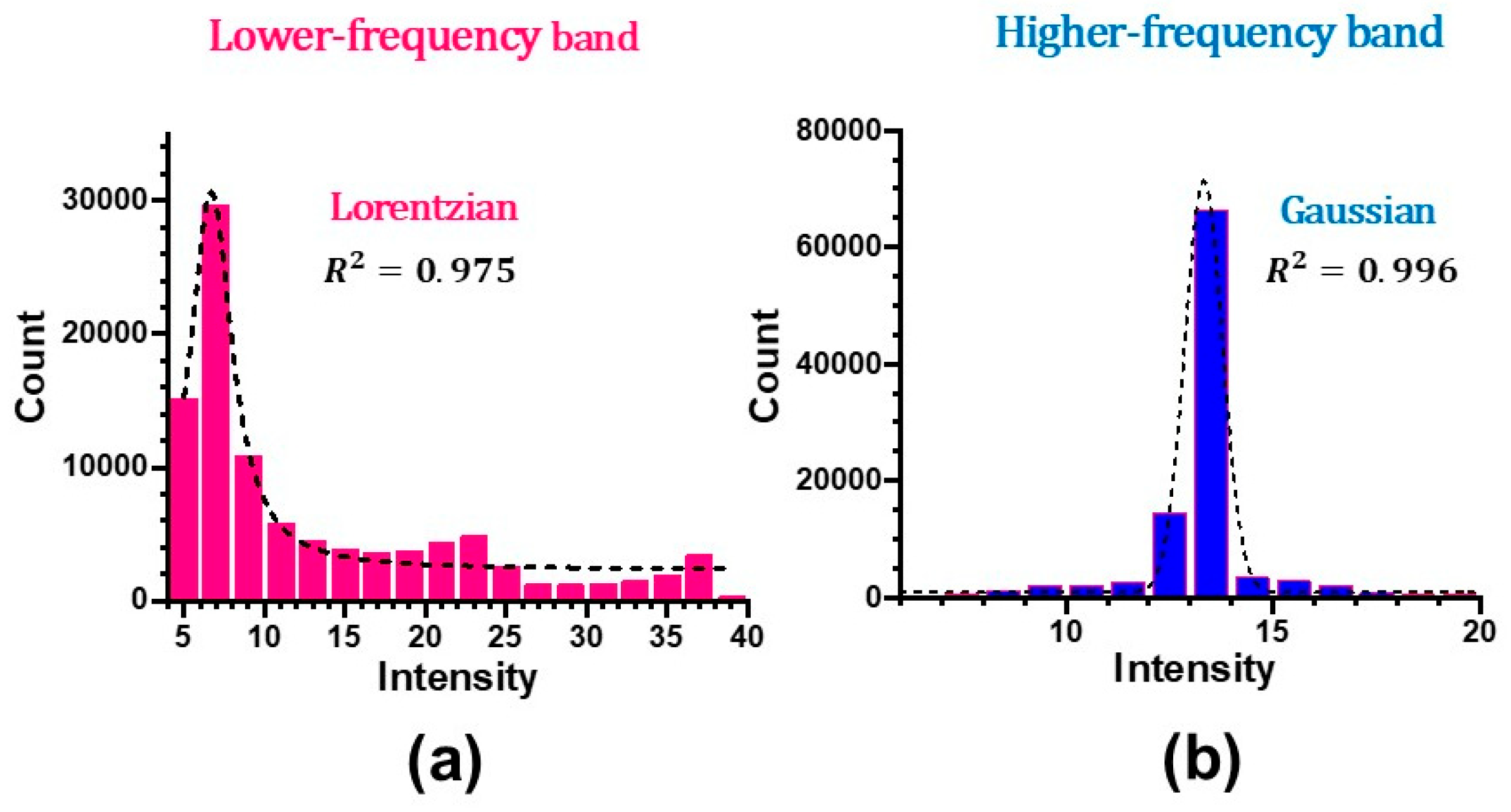
Finally, it is interesting to note that there is a non-trivial correlation between the histogram and power spectra in the present hybrid skew cosh Gauss mode laser system. Figure 16 shows the histograms (i.e., intensity probability distribution) of the output waveforms in the lower and higher frequency bands in the case of intermediate feedback regime shown in Figure 10. They are fitted quite well by Lorentzian and Gaussian distributions, respectively, and exhibit a strong correlation with the power spectra shown in Figure 15b,c. The power spectral nature shown in Figure 15(a) with lateral-coupling resonance of coexisting transverse modes seems to play a crucial role in organizing collective dynamics.
5. Summary and Outlook
The hybrid skew cosh Gaussian mode laser oscillation with the large slope efficiency of 40%, that make use of most of the population inversions in the lateral direction, was demonstrated for the first time in a thin-slice solid-state laser with wide-aperture laser-diode pumping using a 300mm-thick Nd:GdVO4 crystal with coated end mirrors. The large fluorescence-to-photon lifetime ratio of K = 4.5x10⁶ enabled us to perform highly-sensitive self-mixing modulation experiments whose sensitivity is proportional to K2.
The hybrid skew-chG mode laser was proved to be formed by the locking of nearly frequency-degenerate TEM00 and surrounding annular modal fields. The modal-interference-induced gain modulation took place around the beat frequency between modal fields featuring its higher harmonics with increasing the feedback ratio. Such a lateral-mode coupling resonance effect increased the frequency bandwidth beyond the relaxation oscillation frequency for harmonics-assisted phase amplifications, which are brought about by subharmonic modulation at fM = fRO/2 (fRO: relaxation oscillation frequency), leading to fifty-fold phase amplification, N = 50. The observed phenomenon is capable of the phase super-resolution measurement in real time by employing the phase-sensitive detection with a lock-in amplifier, since the phase oscillation is N times faster than the original phase change and the unwrapped phase change against the optical path change becomes N times the original one.
Generally, dynamic changes of any basic physical quantities can be converted to the detection of the phase change of light, including displacement, angle, etc. We believe that harmonic-assisted phase amplifications in the hybrid skew-chG laser, possessing the order-of-magnitude wider modulation bandwidth than conventional self-mixing solid-state lasers, would provide new insights into the super-resolution optical metrologies.
References
- Kogelnikm, H.; Li, T. Laser beams and resonators. Appl. Opt. 1966, 5, 1550–1567. [Google Scholar] [CrossRef]
- Otsuka, K.; Chu, C.-S. Generation of vortex array beams from a thin-slice solid-state laser with shaped wide-aperture laser-diode pumping. Opt. Lett. 2009, 34, 10–13. [Google Scholar]
- Otsuka, K.; Chu, C.-S. Spontaneous generation of vortex and coherent vector beams from a thin-slice c-cut Nd:GdVO4 laser with wide-aperture laser-diode end pumping: application to highly sensitive rotational and translational Doppler velocimetry. Laser Phys. Lett. 2017, 14, 075002–1. [Google Scholar] [CrossRef]
- Otsuka, K.; Sudo, S. Self-mixing interference in a thin-slice solid-state laser with few feedback photons per observation period. Phys. Rev. A 2022, 106, 053504–1. [Google Scholar]
- Otsuka, K. Effects of external perturbations on LiNdP4O12 lasers. IEEE J.Quantum Electron. 1979, 15, 655–663. [Google Scholar] [CrossRef]
- Kawai, R.; Asakawa, Y.; Otsuka, K. Ultrahigh-sensitivity self-mixing laser Doppler velocimetry with laser-diode-pumped microchip LiNdP4O12 lasers. IEEE Photonics Tech. Lett. 1999, 11, 706–708. [Google Scholar]
- Lacot, E.; Day, R.; Pinel, J.; Stoeckel, F. Laser relaxation oscillation- frequency imaging. Opt. Lett. 200, 26, 1483–1485. [Google Scholar] [CrossRef] [PubMed]
- Otsuka, K.; Abe, K.; Ko, J.-Y.; Lim, T.-S. Real-time nanometer-vibration measurement with a self-mixing microchip solid-state laser. Opt. Lett. 2002, 27, 1339–1341. [Google Scholar] [PubMed]
- Sudo, S.; Otsuka, K. Self-mixing thinly sliced ruby laser for laser Doppler velocimetry with high optical sensitivity. Opt. Continuum 2024, 3, 2174–2189. [Google Scholar]
- Otsuka, K. Self-mixing thin-slice solid-state laser metrology. Sensors 2011, 11, 2195–2245. [Google Scholar] [CrossRef]
- Li, J.; Niu, H.; Ni, Y.-X. Laser feedback interferometry and applications: a review. Opt. Eng. 2017, 56, 050901–1. [Google Scholar] [CrossRef]
- Giovannetti, V.; Lloyd, S.; Maccone, L. Quantum-enhanced measurements: beating the standard quantum limit. Science 2004, 306, 1330–1336. [Google Scholar] [CrossRef]
- Mason, D.; Chen, J.; Rossi, M.; Tsaturyan, Y.; Schliesser, A. Continuous force and displacement measurement below the standard quantum limit. Nat. Phys. 2019, 15, 745–749. [Google Scholar] [CrossRef]
- Zhou, Z.-Y.; Ding, D.-S.; Jiang, Y.-K.; Li, Y.; Shuai, S.; Wang, X.-S.; Shi, B.S. Orbital angular momentum light frequency conversion and interference with quasi-phase matching crystals. Opt. Express 2014, 22, 20298–20310. [Google Scholar] [CrossRef] [PubMed]
- Nagata, T.; Okamoto, R.; O’Brien, R.J.; Sasaki, K.; Takeuchi, S. Beating the standard quantum limit with four-entangled photons. Science 2007, 316, 726–729. [Google Scholar] [CrossRef] [PubMed]
- Tian, N.; Tan, Y. Intracavity-dynamics-based optical phase amplifier with over tenfold amplification. Photonic Research 2023, 11, 1892–1901. [Google Scholar] [CrossRef]
- Georgi, P.; Massaro, M.; Luo, K.-H.; Sain, B.; Montaut, N.; Herrmann, H.; Weiss, T.; Li, G.; Silberhorn, C.; Zentgraf, T. Metasurface interferometry toward quantum sensors. Light Sci. Appl. 2019, 8, 1–7. [Google Scholar] [CrossRef]
- Asakawa, Y.; Kawai, R.; Ohki, K.; Otsuka, K. Laser-diode-pumped microchip LiNdP4O12 lasers under different pump-beam focusing conditions. Jpn. J. Appl. Phys. 1999, 38, L515–L517. [Google Scholar] [CrossRef]
- Salin, F.; Squier, J. Gain guiding in solid-state lasers. Opt. Lett. 1992, 17, 1352–1354. [Google Scholar] [CrossRef]
- Jacinto, C.; Messias, D.N.; Andrade, A.A.; Lima, S.M.; Baesso, M.L.; Catunda, T. Thermal lens and Z-scan measurements: Thermal and optical properties of laser glasses – A review. J. Non-Cryst. Solids 2006, 352, 3582–3597. [Google Scholar] [CrossRef]
- Godin, T.; Moncorgé, R.; Doualan, J.-L.; Fromager, M.; Ait-Ameur, K.; Antonio Cruz, A.; Catunda, T. Optically pump-induced athermal and nonresonant refractive index changes in the reference Cr-doped laser materials: Cr:GSGG and ruby. J. Opt. Soc. Am. 2012, 29, 1055–1064. [Google Scholar] [CrossRef]
- Otsuka, K. Self-mixng thin-slice solid-state laser Doppler velocimetry much less than one feeback photon per Doppler cycle. Opt. Lett. 2015, 40, 4603–4606. [Google Scholar] [CrossRef] [PubMed]
- Otsuka, K.; Aizawa, Y. Gain circulation in multimode lasers. Phys. Rev. Lett. 1994, 72, 2701–2704. [Google Scholar] [CrossRef] [PubMed]
- Otsuka, K.; Sato, Y.; Chern, J.-Y. Grouping of antiphase oscillations in modulated multimode lasers. Phys. Rev. A 1996, 54, 4464–4472. [Google Scholar] [CrossRef] [PubMed]
- Otsuka, K.; Mandel, P.; Georgiou, M.; Etrich, C. Antiphase dynamics in a modulated multimode laser. Japanese Journal of Applied Physics 1993, 32, L318–L321. [Google Scholar] [CrossRef]
- Taimre, T.; Nikolic, M.; Bertling, K.; Lim, Y.L.; Bosch, T.; Rakic, A.D. Laser feedback interferometry: a tutorial on the self-mixing effect for coherent sensing. Advances in Optics and Photonics 2015, 7, 570–631. [Google Scholar] [CrossRef]
- Lamela, H.; Roycroft, B.; Acedo, P.; Santos, R.; Carpintero, G. Experimental modulation bandwidth beyond the relaxation oscillation frequency in a monolithic twin-ridge laterally coupled diode laser based on lateral mode locking. Opt. Lett. 2002, 27, 303–305. [Google Scholar] [CrossRef]
- Dods, S.R.A.; Ogura, M.; Watanabe, M. Small-signal analysis of semiconductor lasers modulated at frequencies on the order of the beat frequency. IEEE J. Quantum. Electron. 1993, 29, 2631–2638. [Google Scholar] [CrossRef]
Figure 1.
Experimental apparatus of a thin-slice Nd:GdVO4 laser with LD pumping for harmonics-assisted phase amplification. Input-output characteristics for different pump spot sizes, i.e., mode-matching wpwo and wide-aperture pumping, wp > wo, where wo is the lasing spot size. AP: anamorphic prism pair, OL: objective lens, VA: variable optical attenuator, PD: photo-diode, DO: digital oscilloscope (Tektronix TDS 3052, DC – 500 MHz), SA: spectrum analyzer (Tektronix 2712, 9kHz-18GHz).
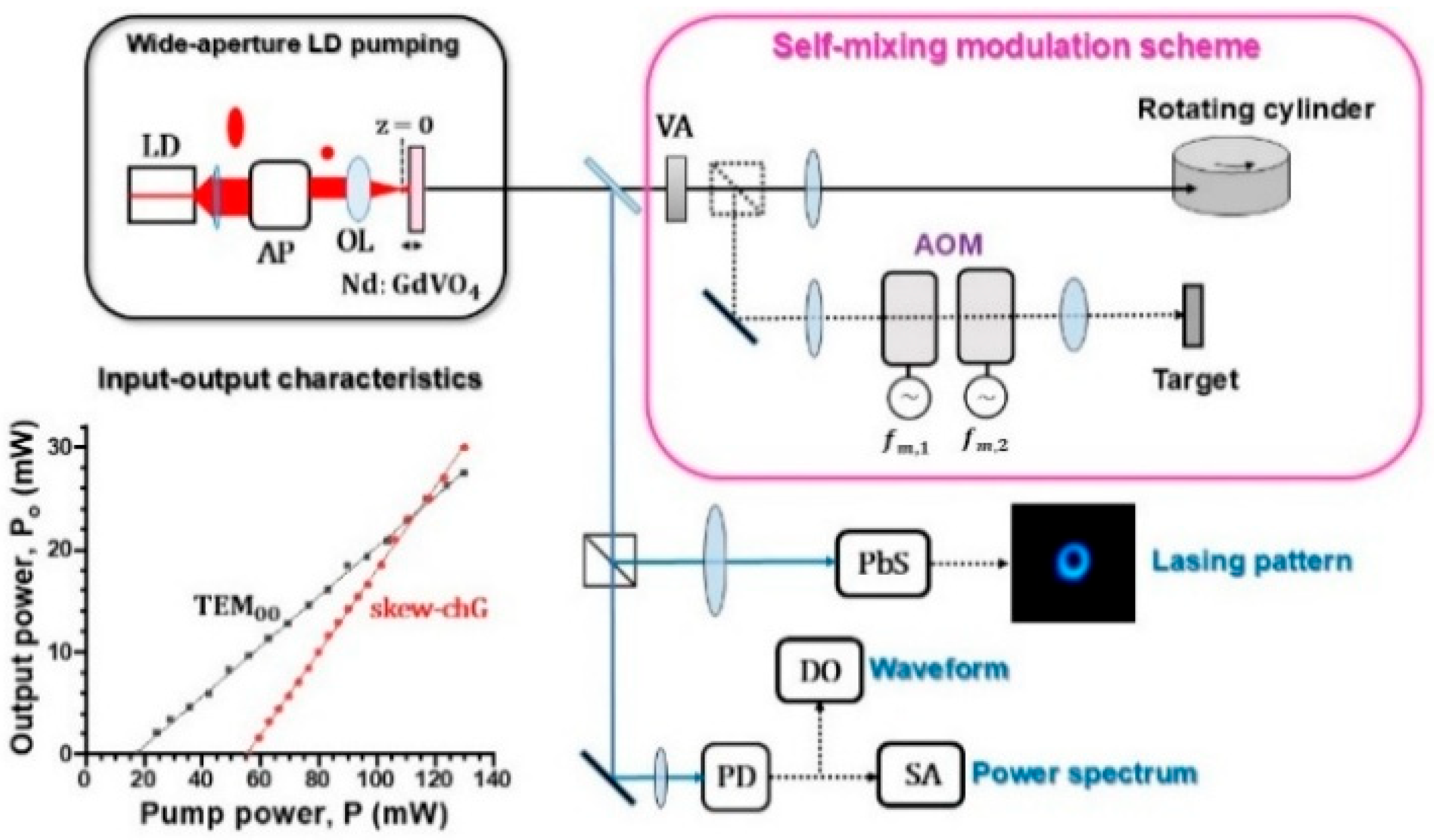
Figure 2.
Pump-dependent lasing near- and far-field patterns of thin-slice Nd:GdVO4 laser with wide-aperture LD pumping. See Supplementary Material 1 (near-field) and 2 (far-field).
Figure 2.
Pump-dependent lasing near- and far-field patterns of thin-slice Nd:GdVO4 laser with wide-aperture LD pumping. See Supplementary Material 1 (near-field) and 2 (far-field).
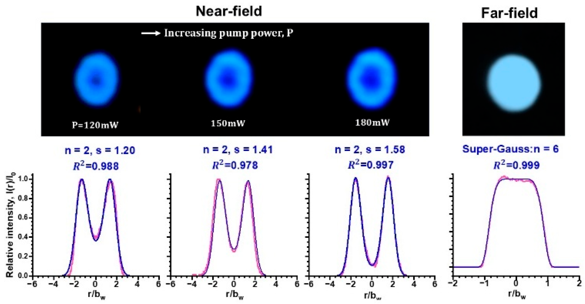
Figure 3.
Calculated spot sizes at the crystal for the TEM00 mode that arises from the thermal lens effect.
Figure 3.
Calculated spot sizes at the crystal for the TEM00 mode that arises from the thermal lens effect.
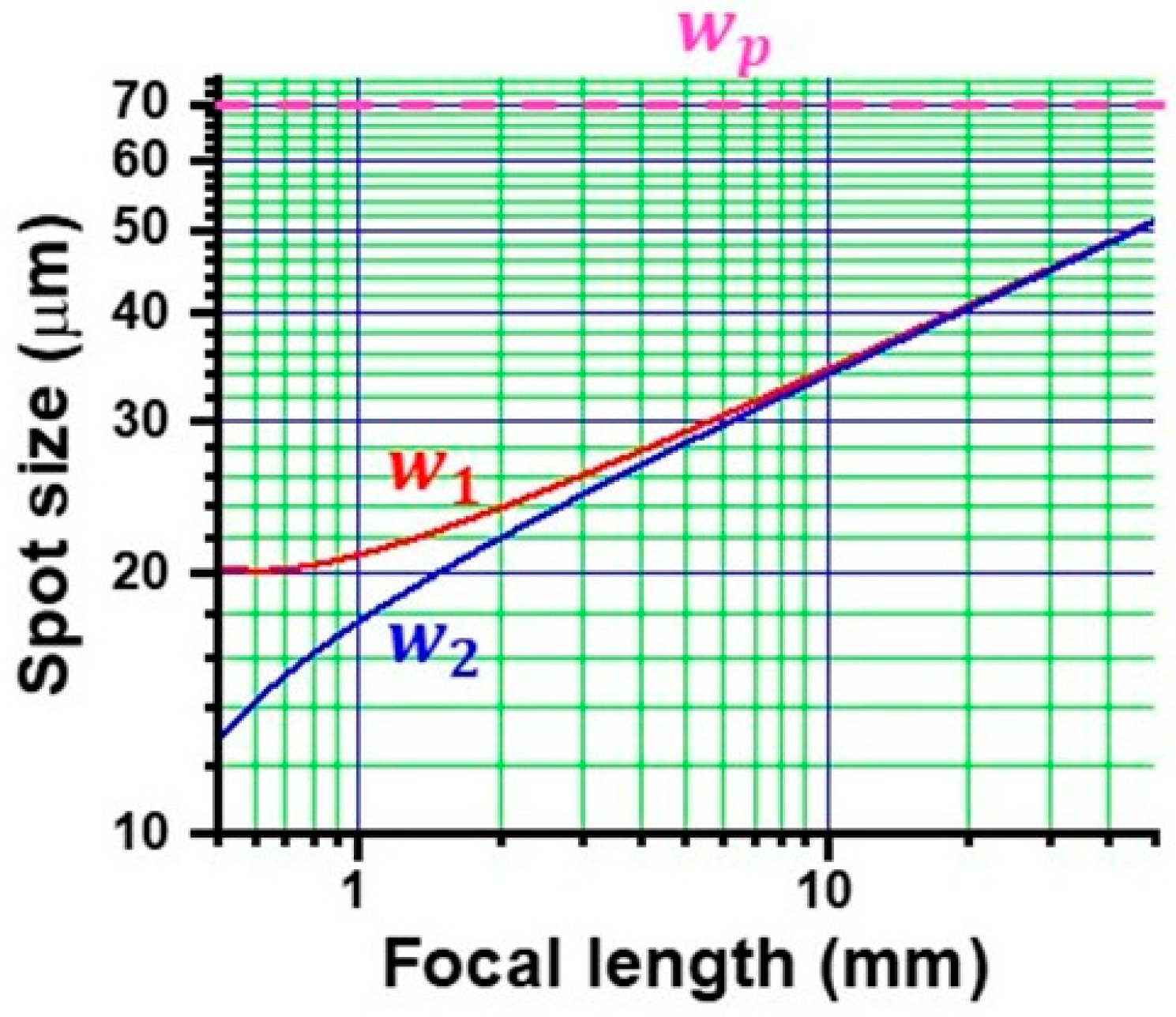
Figure 4.
(a) Relative pump-dependent circulating photon emission rate of TEM00 mode. (b) Relative atom excitation rate in the presence of TEM00 mode. (c) Effective atom excitation for annular fields. Pump power in (b) and (c) is indicated by the same color as (a).
Figure 4.
(a) Relative pump-dependent circulating photon emission rate of TEM00 mode. (b) Relative atom excitation rate in the presence of TEM00 mode. (c) Effective atom excitation for annular fields. Pump power in (b) and (c) is indicated by the same color as (a).
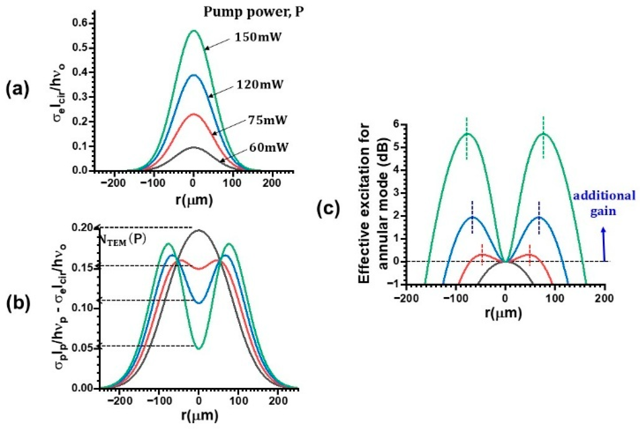
Figure 5.
Reconstruction of the observed modified skew ch-G profile shown in Figure 2 by assuming the phase locking of nearly frequency-degenerate Gaussian modal field and the annular field with the fixed relative phase of p/2.
Figure 5.
Reconstruction of the observed modified skew ch-G profile shown in Figure 2 by assuming the phase locking of nearly frequency-degenerate Gaussian modal field and the annular field with the fixed relative phase of p/2.
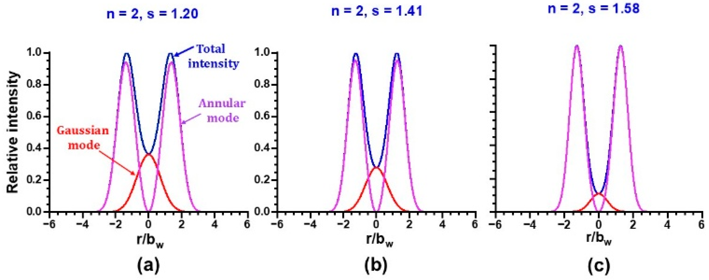
Figure 6.
(a) Dependence of fRO on the excess pump rate, w – 1. (b), (c) Waveforms and corresponding power spectra under the weak feedback regime, where fM = fRO/2=2MHz. Pump power, P = 120 mW.
Figure 6.
(a) Dependence of fRO on the excess pump rate, w – 1. (b), (c) Waveforms and corresponding power spectra under the weak feedback regime, where fM = fRO/2=2MHz. Pump power, P = 120 mW.
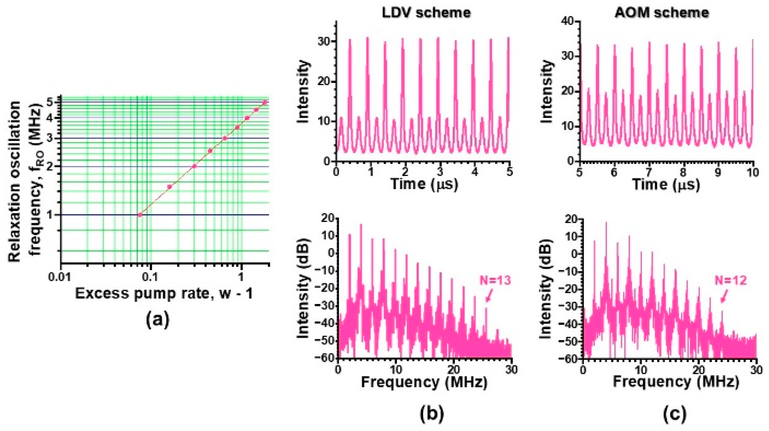
Figure 7.
(a) Original and reconstructed self-mixing LDV signals. (b) Correlation plots indicating R2=0.997.
Figure 7.
(a) Original and reconstructed self-mixing LDV signals. (b) Correlation plots indicating R2=0.997.
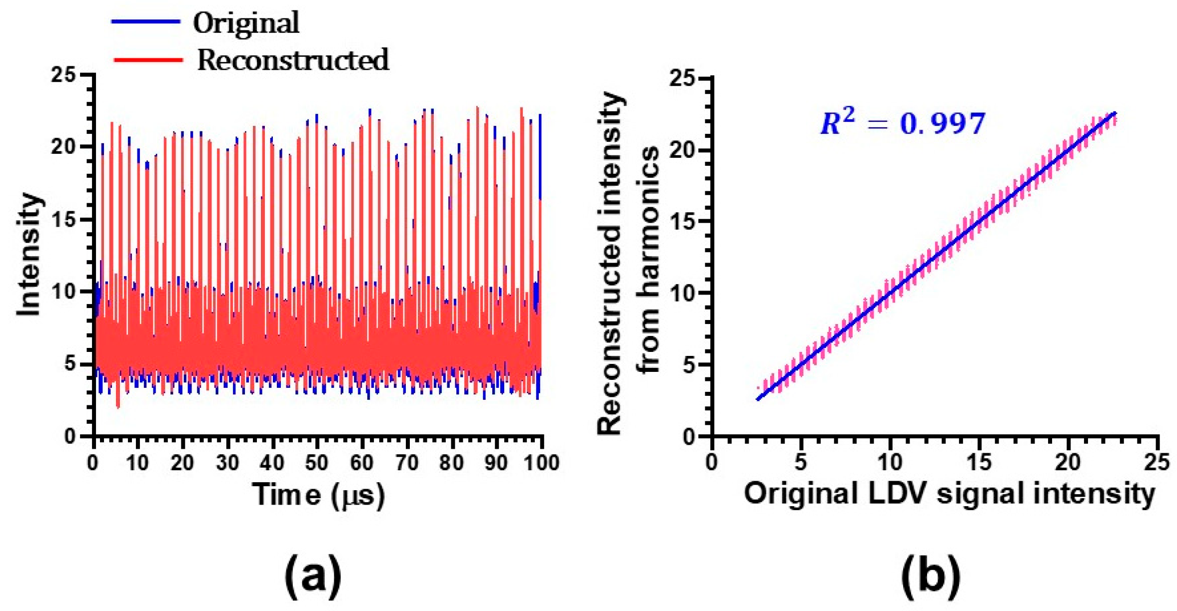
Figure 8.
(a), (b) Example harmonic waves for LDV and AOM self-mixing schemes, which were obtained experimentally. Theoretical harmonic waves, assuming D = 1.601 for (a’) and 1.505 for (b’).
Figure 8.
(a), (b) Example harmonic waves for LDV and AOM self-mixing schemes, which were obtained experimentally. Theoretical harmonic waves, assuming D = 1.601 for (a’) and 1.505 for (b’).
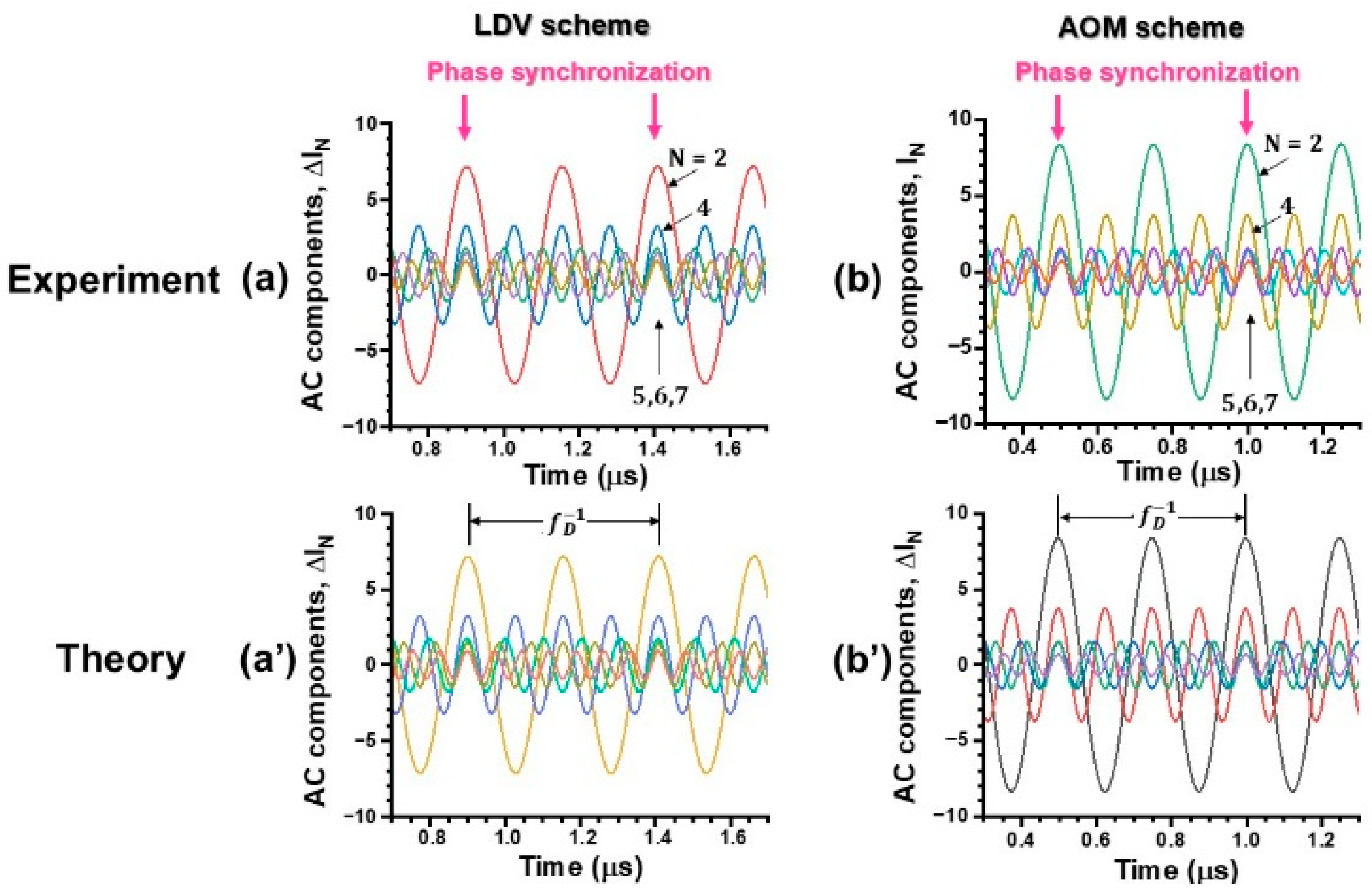
Figure 9.
Phase synchronization up to N = 19 harmonics. P = 62 mW. (a) LDV signal waveform, (b) Power spectrum, (c) Poincare map corresponding to the period-2 total output waveform.
Figure 9.
Phase synchronization up to N = 19 harmonics. P = 62 mW. (a) LDV signal waveform, (b) Power spectrum, (c) Poincare map corresponding to the period-2 total output waveform.
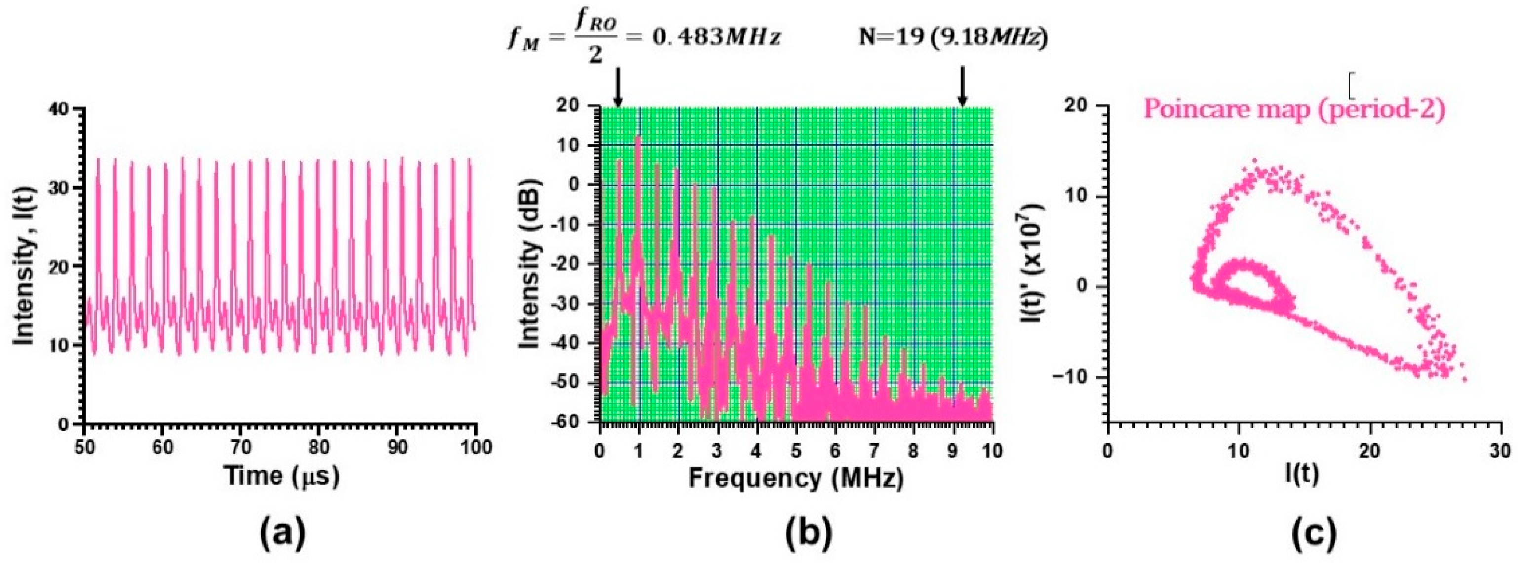
Figure 10.
Response of skew ch-G laser subjected to self-mixing LDV. The total output in the lower- and higher-frequency band is shown in the middle plot in (b). P = 120 mW.
Figure 10.
Response of skew ch-G laser subjected to self-mixing LDV. The total output in the lower- and higher-frequency band is shown in the middle plot in (b). P = 120 mW.
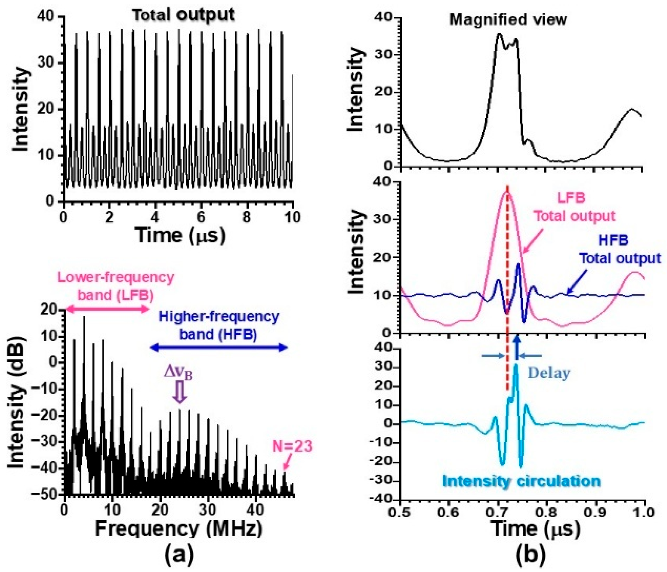
Figure 11.
(a) Phase synchronization among harmonics in the higher-frequency band. (b) Phase relationship between harmonics in the higher-frequency band and the fundamental wave at 2MHz in the lower frequency band depicted by red. (c) Total intensity waveform belonging to the higher-frequency band exhibiting antiphase dynamics against the lower frequency band. P = 120mW.
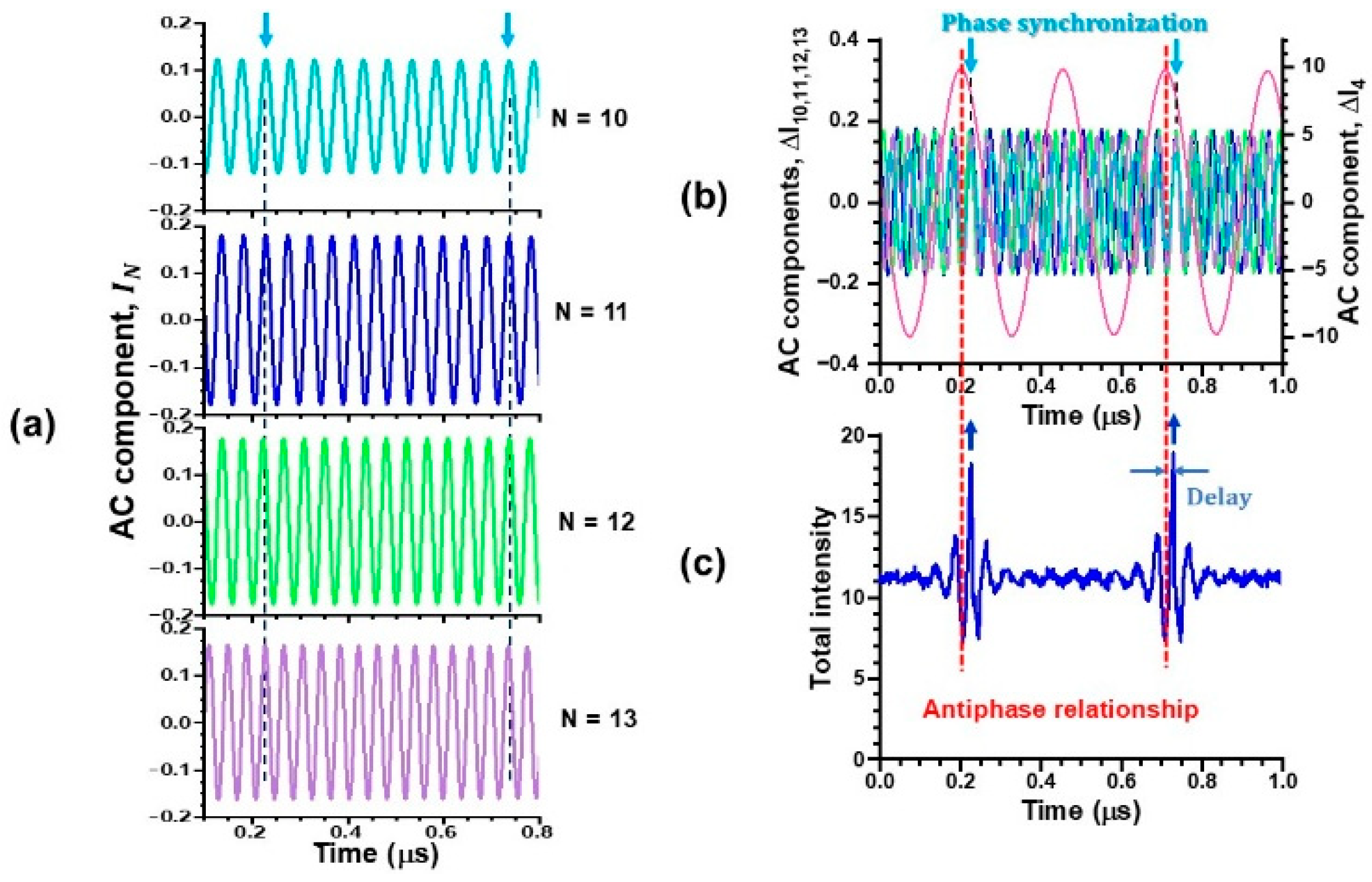
Figure 12.
Subharmonic resonance observed in the AOM feedback scheme. (a) Oscillation wave form together with a magnified view and the corresponding power spectrum. (b) Typical waveforms of the N-th harmonics and their phase relations with the total intensity waveform belonging to the higher frequency band. P = 120 mW.
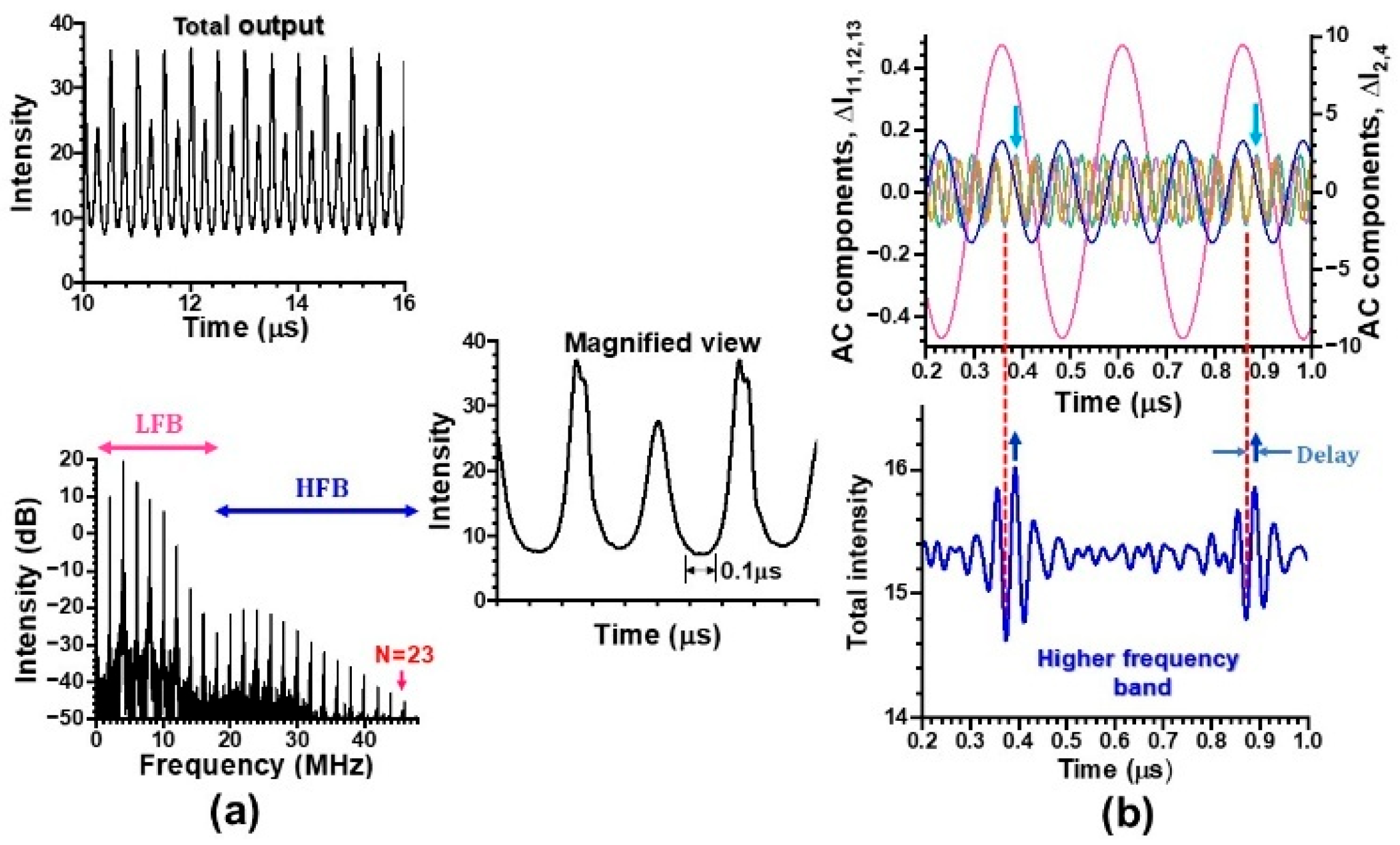
Figure 13.
(a) Self-mixing modulation waveform and the corresponding power spectrum in strong feedback regime. (b) Magnified view of outputs in low- and high-frequency bands. (c) Phase-locking among harmonics up to N = 30. P = 120 mW.
Figure 13.
(a) Self-mixing modulation waveform and the corresponding power spectrum in strong feedback regime. (b) Magnified view of outputs in low- and high-frequency bands. (c) Phase-locking among harmonics up to N = 30. P = 120 mW.
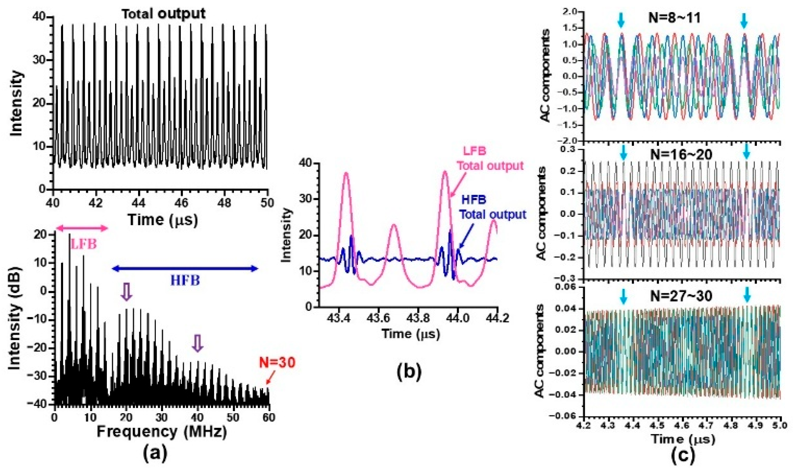
Figure 14.
Fifty-fold phase amplification with the decreased pump power in the absence of VA. fM = fRO/2 = 1 MHz. P = 75 mW.
Figure 14.
Fifty-fold phase amplification with the decreased pump power in the absence of VA. fM = fRO/2 = 1 MHz. P = 75 mW.
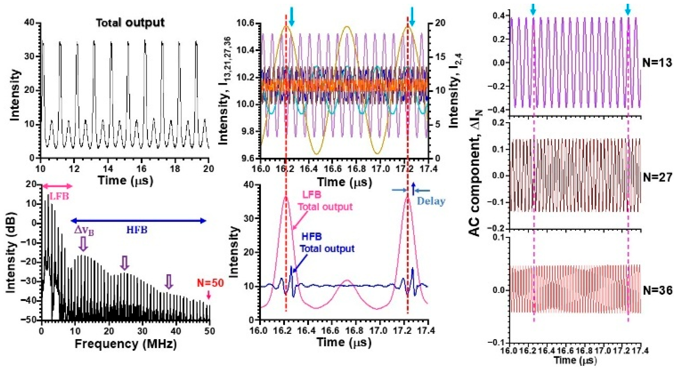
Figure 15.
(a) Power spectrum in skew ch-G operation under the free-running condition. (b), (c) Power spectral intensity of harmonics in the intermediate feedback regime. P =120mW.
Figure 15.
(a) Power spectrum in skew ch-G operation under the free-running condition. (b), (c) Power spectral intensity of harmonics in the intermediate feedback regime. P =120mW.
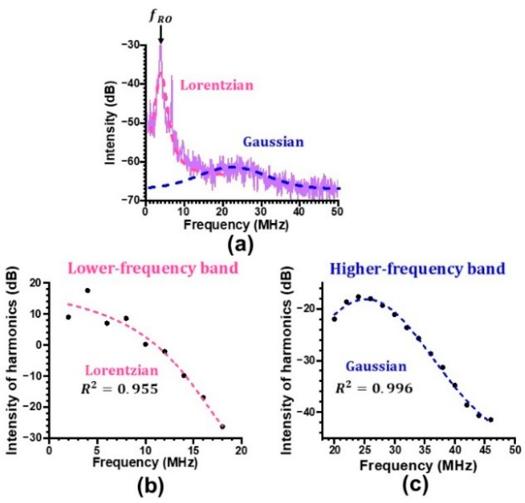
Figure 16.
Histogram for total output intensity in (a) lower-frequency band and (b) higher-frequency band in the intermediate feedback regime. P = 120 mW, fM = fRO/2= 2MHz.
Figure 16.
Histogram for total output intensity in (a) lower-frequency band and (b) higher-frequency band in the intermediate feedback regime. P = 120 mW, fM = fRO/2= 2MHz.
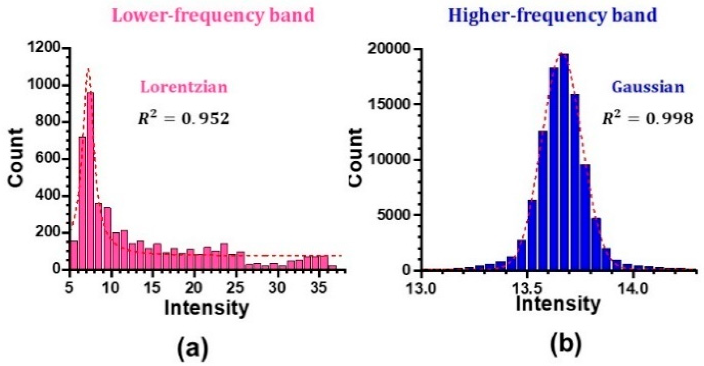
Figure 17.
Histogram for total output intensity in (a) lower-frequency band and (b) higher-frequency band in the strong feedback regime. P = 120 mW, fM = fRO/2 = 2MHz.
Figure 17.
Histogram for total output intensity in (a) lower-frequency band and (b) higher-frequency band in the strong feedback regime. P = 120 mW, fM = fRO/2 = 2MHz.
Disclaimer/Publisher’s Note: The statements, opinions and data contained in all publications are solely those of the individual author(s) and contributor(s) and not of MDPI and/or the editor(s). MDPI and/or the editor(s) disclaim responsibility for any injury to people or property resulting from any ideas, methods, instructions or products referred to in the content. |
© 2025 by the authors. Licensee MDPI, Basel, Switzerland. This article is an open access article distributed under the terms and conditions of the Creative Commons Attribution (CC BY) license (http://creativecommons.org/licenses/by/4.0/).
Copyright: This open access article is published under a Creative Commons CC BY 4.0 license, which permit the free download, distribution, and reuse, provided that the author and preprint are cited in any reuse.


