
Submitted:
31 August 2023
Posted:
01 September 2023
You are already at the latest version
Abstract
This study explores into a comprehensive examination of an optical cavity system that integrates Raman and Yb-doped gain media, with a focus on understanding their interactions. The research implies a characterization of each gain medium within the cavity while subjecting them to diverse co-pumping conditions with the other. When the Raman-lasing cavity is co-pumped by exciting the Yb-doped section, the resulting composite laser exhibits significant threshold reductions and there is an optimal co-pumping regime that enhances energy transfer from pump to Stokes. As for the complementary cavity, where the Yb-doped gain is influenced by the co-pumped Raman gain, at moderate pump powers a light-controlling-light behavior phenomenon arises. Within this regime, the 1064-nm signal suppresses the Yb-generated 1115-nm signal, suggesting potential applications in intracavity optical modulation. For higher pump levels, a cooperative effect emerges whereby both lasers mutually enhance each other. Minor variations in the primary 974-nm pump power, even by just a few milliwatts, result in significant capabilities for switching or modulating the Stokes signal. Under these conditions of mutual enhancement, the hybrid optical system validates notable improvements regarding energy transfer efficiency and threshold reduction. This research provides valuable insights into the intricate dynamics of optical cavity systems and reveals promising avenues for applications in advanced optical modulation technologies.
Keywords:
Raman Fiber Lasers
; Ytterbium-doped Fiber Lasers
; Stimulated Raman Scattering
; Amplified Spontaneous emission
1. Introduction
Over the past two decades, research efforts in the domains of Raman fiber lasers (RFLs) and ytterbium-doped fiber lasers (YbDFLs) have experienced a substantial surge in activity. This heightened interest is primarily attributable to their exceptional performance characteristics and their potential applications across a wide spectrum of research and industrial fields [1,2,3]. It is worth noting that both RFLs and YbDFLs operate within a shared wavelength range, spanning from just below 1000 nm to 1200 nm [4,5,6]. This specific emission range is defined by the radiative properties of Yb3+ ions embedded within the glass of optical fibers [7,8]. As previously established, the emissions spanning from 976 to 1200 nm in ytterbium-doped fibers (YbDFs) play a crucial role in facilitating the generation of the lowest Raman-generated Stokes components within 1064-nm pumped silica fibers. Specifically, these emissions manifest at 1115 nm and 1175 nm [9]. In a parallel line of inquiry, which underpins the complementary hypothesis of our research, these YbDF emissions may also offer amplification capabilities to a Raman fiber laser (RFL). Indeed, the convergence of these two distinct types of fiber lasers, one based on rare earth-doped media and the other relying on Raman scattering, in a cooperative operating mode, forms the core of the investigations reported herein.
In this study, we initiated the experimentation by pumping a Raman fiber laser cavity containing an un-pumped segment of YbDF. This YbDF segment was subjected to co-pumping using a 974-nm laser diode. Subsequently, we directed our attention to the YbDFL cavity, which encompassed an extended silica fiber segment that was similarly un-pumped and co-pumped at 1064 nm. Through this experimental setup, we systematically characterized the system under both operating conditions, meticulously evaluating the advantages and disadvantages inherent in each configuration within the composite laser cavity.
2. Experiments
After several tries, we determined that the experimental setup illustrated in Figure 1 was the most suitable for testing our hypotheses. In this, a single-spatial mode continuous-wave (CW) 1064-nm fiber laser from IPG-Photonics® was collimated and passed through an optical isolator (OI) towards a 10X focusing lens that coupled into the arm a of a wavelength division multiplexer (WDM). The WDM transmitted 61% of the 1064-nm light through arm c, while transmitting only 3% of it through arm d, the complimentary 36% is the insertion loss and it was polarization independent. The pumping arm c was spliced to a fiber Bragg grating (FBG) based hybrid cavity of the nested type consisting on two close-to 95% reflectance for first Stokes (1115 nm) and a pair of ~87% for second Stokes (1176 nm). The composed gain medium included a 4.7-km (quasi-single mode, 6.5-micron core diameter) TrueWave® silica fiber for the Raman gain; it was spliced to a 6-micron core (single mode) 1.5-meter length 1.25-% concentration YBDF as the complimentary gain medium. The YbDF was pumped at the opposite end of the cavity by a 974-nm laser diode (LD) that provided up to 250 mW, as depicted on the upper left of the figure.
The methodology for the experiments started by first characterizing the composed cavity with 1064-nm pumping alone and then, also pumping alone, with 974-nm. After this, we pumped for each type of gain while simultaneously pumping the other one. The signals generated were monitored at arm b of the WDM whose transmittances of signals coming from arm c are ~50% of 1115 nm, ~7% of backscattered 1064 nm and ~17% of the second Stokes (~55% goes to arm a and blocked by the OI).
3. Results and discussions
As previously outlined, the characterizations were essentially divided into two distinct approaches, as expounded upon immediately below.
3.1. The co-pumped Raman cavity
When coupling pump powers to the Raman gain within the cavity at point 6 of Figure 1, spanning a power range from 0 W to 1.1 W, we conducted measurements to determine the first Stokes powers delivered at the output arm of the WDM. The resulting data is graphically represented by the black curves in Figure 2. Note that the Stokes commenced its generation at approximately 0.35 W. It's worth noting that there is a noticeable inflection point at around 0.55 W. This inflection point signifies an energy transfer from the first Stokes component to the second Stokes component, as illustrated by the black plot in Figure 3. This plot illustrates power levels corresponding to the delivery of approximately 17% of the backward-generated second Stokes signal.
Please note that the first Stokes signal reaches its maximum intensity when the pumping power exceeds 0.7 W, resulting in an output of approximately 44 mW. This corresponds to the point at which energy transfer to the second Stokes signal becomes dominant. As the pump power reaches its maximum of 1.1 W, the intensity of the first Stokes signal is reduced to around 40% of its peak value, allowing the second Stokes signal to absorb the majority of the available energy.
The red plots in Figure 2 and Figure 3 correspond to the co-pumping of the YbDF in the opposite direction. Notice the distinct changes in Stokes signal generation for various pump levels of the 974-nm signal. For instance, in Figure 2a, there is a subtle threshold reduction for the first Stokes generation when co-pumping with 54.3 mW. This trend of lowering the threshold persists as these levels increase, becoming more pronounced when co-pumping with 124 mW, which decreases the threshold from 0.35 W down to 0.3 W (Figure 2b). With 167 mW, it decreases to 0.27 W (Figure 2c), with 181 mW down to 0.24 W (Figure 2d), with 195 mW down to 0.2 W (Figure 2e), and with 227 mW down to 0.1 W (Figure 2f). In summary, there is a 71% reduction in the threshold, decreasing from 0.35 W to 0.1 W, with the total available power of 227 mW.
When analyzing the changes in energy transfer induced by co-pumping, let's compare the red plots with the black ones in all the insets of Figure 2 and Figure 3. Regarding the first Stokes signal (Figure 2), as mentioned earlier, it begins generating earlier with co-pumping. However, it also depletes earlier, and in most cases, except for Figure 2e, its curve reaches a lower peak intensity. This indicates an earlier initiation of energy transfer to the next Stokes component. It's important to note that for the second Stokes signal (Figure 3), except in the case of Figure 3e, it is also generated earlier with co-pumping. However, it is at this co-pump level that, above threshold, it is not only generated more efficiently but also notably reaches higher power. In summary, these results suggest that both Stokes components generate earlier when assisted by the pumped Yb ions, leading to an increase in the overall system efficiency. Additionally, regarding Figure 2e and Figure 3e, it appears that there exists an optimal co-pump power level. This level not only enhances the efficiency of the generated Stokes but also maximizes the energy transfer from the pump to both Stokes signals.
3.2. The co-pumped Yb-doped cavity
When pumping the Yb-doped gain of the cavity above threshold, with 0.148 W, the cavity emitted at 1115 nm as shown in Figure 4a. Note that the intensity was normalize to 1. Now, turning off the 974-nm whereas pumping the Raman gain medium below threshold (0.2 W), the cavity did not oscillate and only the backscattered pump was present as displayed in Figure 4b. Turning on again the 974-nm pump, we obtained the “combined” behavior depicted in Figure 4c.
It’s worth noting that the laser line at 1115 nm originating from Yb becomes completely suppressed by the 1064 nm signal, which experiences amplification (from 0.5 to 0.8). This outcome holds significant promise for potential applications in light-controlling-light-based modulators [10,11]. In this scenario, the 1064 nm signal effectively governs and manipulates the energy that would otherwise produce the 1115 nm signal. This modulating mechanism’s underlying phenomenon can be explained by the fact that the inverted population amplifies the 1064 nm signal rather than the 1115 nm signal. This preference for the 1064 nm signal is due to its proximity to the peak amplification of the Yb3+ ions, which is typically centered around 1040 nm [12].
By further increasing the pump power of the 1064-nm laser by approximately 30% (0.29 W), while still remaining below the pure Raman oscillation threshold of 0.35 W, the system transitions into what we term as the “composite” operational state, as visually represented in Figure 5c. In this configuration, the 1115-nm component generated by the Yb ions within the cavity continues to be partially suppressed by the amplified 1064-nm signal. Consequently, in a light-controlling-light system, the controlling signal (1064-nm) exceeds its anticipated level because the 1115-nm signal is not completely suppressed. We speculate that the amplified 1064-nm signal contributes to an increase in spontaneous Raman scattering (RS). This RS, combined with the portion of amplified spontaneous emission (ASE) produced by the Yb ions that coincides with the FBGs, may trigger stimulated Raman scattering (SRS) and/or the 1115-nm Yb signal within the high-Q cavity. Under these conditions, it becomes challenging to definitively determine whether it operates as a RFL, a YbDFL, or a hybrid of both. Hence, it is imperative to conduct further experiments, which fall beyond the scope of this study, to gain a comprehensive understanding and characterize this behavior.
The complete characterization of the cavity operating as a YbDFL, with no 1064-nm signal (0W), is depicted by curve (a) in Figure 6. The lasing threshold for this configuration was approximately 138 mW of the 974-nm signal. Notably, at the maximum pump power of 227 mW, the laser delivered an output of approximately 9.6 mW. Furthermore, Figure 6 includes additional curves that represent the laser behavior for various 1064-nm co-pump signal levels, specifically: (b) 0.7 W, (c) 0.9 W, and (d) 1 W.
It’s worth noting that despite the co-pump powers of 0.7 W and 0.9 W being higher than the pure Raman threshold of 0.35 W, both the threshold and efficiency of the YbFL are notably affected. It’s at the 1.0 W co-pump power level when the combined synergy becomes significant. At this point, the threshold drops significantly from 160 mW to 115 mW, marking a substantial 28% reduction. Moreover, the efficiency improves dramatically, increasing by 230 %, even though the pump power only increased by 10%. This demonstrates a remarkable improvement in both the threshold and efficiency under the influence of this co-pumping synergy.
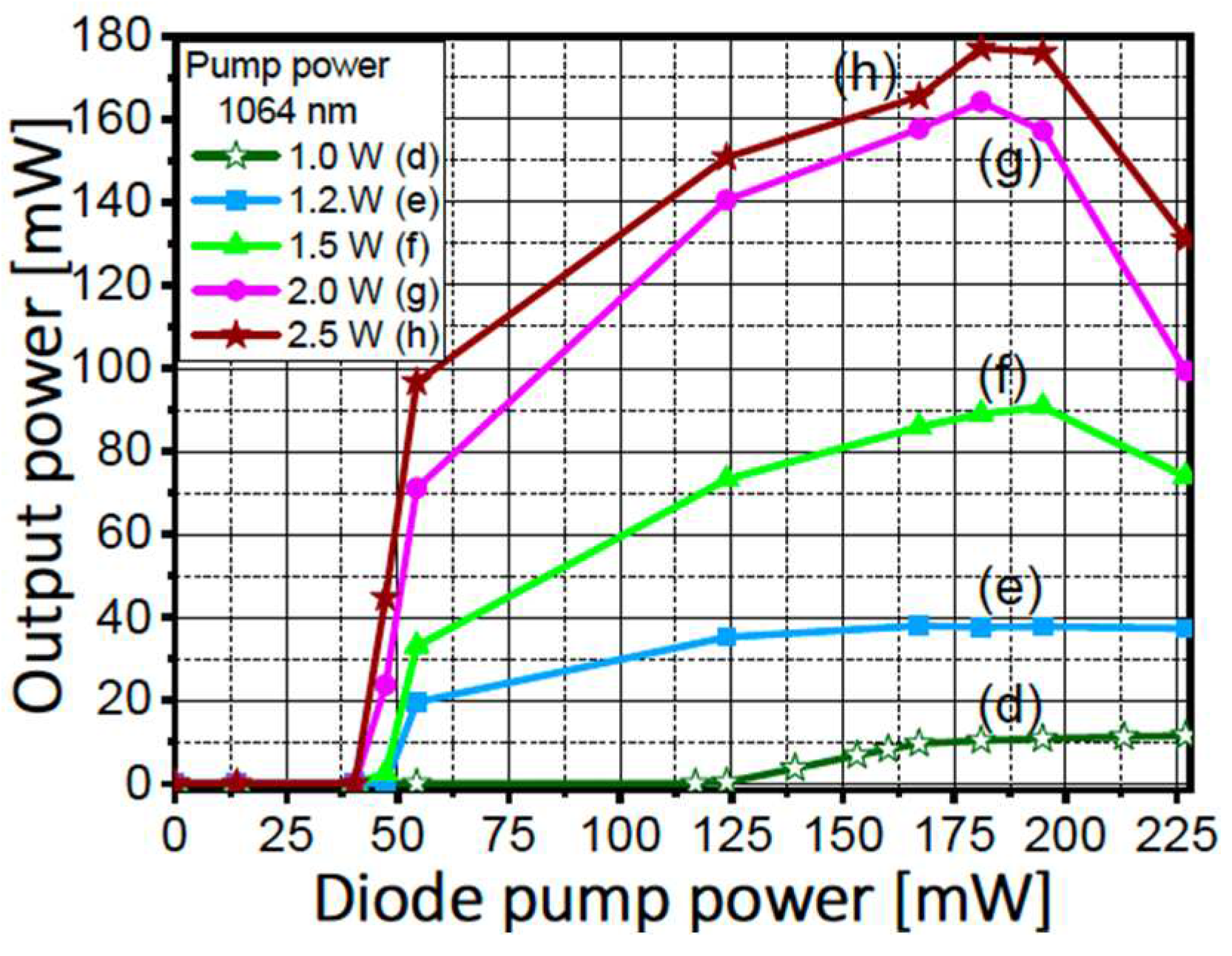
In Figure 7, we present similar characterizations corresponding to co-pump powers equal to or greater than the well-established combination of both laser systems sharing the same cavity. Curve (d) corresponds to the optimal performance seen in Figure 6. When we add an additional 0.2 W of co-pumping power, representing a 20% increase, the threshold is significantly reduced by 58% (from 115 mW to 48 mW). Simultaneously, the efficiency experiences a remarkable 330% increase, climbing from 11.5 mW to 38 mW. It’s important to highlight that for this level, and the subsequent ones, there is a steep slope just above the threshold. In other words, small variations, on the order of a few milliwatts, in the power range from 40 to 48 mW, result in a significant increase in the delivered signal. For instance, with a 2.5 W co-pump (curve h), an increase of approximately 12 mW leads to a jump in the delivered signal from zero to 98 mW. Once again, in a light-controlling-light system, a relatively small 974-nm signal can effectively control, switch, or modulate a much larger first Stokes signal that is an order of magnitude stronger. This behavior also indicates an early initiation of energy transfer from the first to the second Stokes component. This is evident as the curve drastically bends, leading to first Stokes depletion for diode pump powers around 180 mW and co-pump powers of 1.5 W, 2.0 W, and 2.5 W (curves f, g, and h in Figure 7).
4. Conclusions
In conclusion, our study underscores the exciting prospects of harnessing the synergistic potential between distinct gain media within optical cavities. Specifically, in the Raman process, co-pumping within the Yb-doped cavity showcased significant reductions in threshold values and enhancements in efficiency. In this, optimal enhancements consisted on the right adjustment of the co-pumping levels. Conversely, within the Yb-doped enhanced cavity, we observed captivating light-controlling-light phenomena, opening doors to advanced modulation applications like mode-locking or Q-switching. In this configuration, we observed substantial mutual enhancements that synergistically reduced thresholds and improved efficiency. This research underscores the promise of innovative optical cavity designs adaptable for a wide range of applications in photonics, telecommunications, and beyond, presenting novel opportunities for controlling and modulating light.
Author Contributions
Conceptualization, Efrain Mejia-Beltran; Data curation, Oscar Ballesteros-Llanos; Funding acquisition, Efrain Mejia-Beltran; Investigation, Oscar Ballesteros-Llanos; Methodology, Efrain Mejia-Beltran and Oscar Ballesteros-Llanos; Supervision, Efrain Mejia-Beltran; Visualization, Oscar Ballesteros-Llanos; Writing – original draft, Efrain Mejia-Beltran; Writing – review & editing, Efrain Mejia-Beltran and Oscar Ballesteros-Llanos.
Acknowledgments
This work was supported by the Mexican National Council of Science and Technology, CONACYT, under grant reference CB-2011-01/166740 and scholarship No. 339086.
References
- J. Bromage. Raman Amplification for Fiber Communications Systems. J. Lightw. Technol. 2004, 22, 79–93. [CrossRef]
- Georgiev, D.; Gapontsev, V.P.; Dronov, A.G.; Vyatkin, M.Y.; Rulkov, A. B.; Popov, S.V.; Taylor, J.R. Watts-level frequency doubling of a narrow line linearly polarized Raman fiber laser to 589 nm. Opt. Exp. 2005, 13, 6772–6776. [Google Scholar] [CrossRef] [PubMed]
- Feng, Y.; Taylor, L.; and Bonaccini Calia, D. 25 W Raman-fiber-amplifier-based 589 nm laser for laser guide star. Opt. Exp. 2009, 17, 19021–19026. [Google Scholar] [CrossRef] [PubMed]
- 4. Frazäo; C. Correia; M. T. M. Rocco Giraldi; M. B. Marques; H. MSalgado; M. A. G. Martinez; J. C. A. Costa; A. P. Barbero; and J. M. Baptista. Stimulated Raman scattering and its applications in optical communications and optical sensors. Open Opt. J. 2009, 3, 1–11. [CrossRef]
- Eugeni, M. Dianov. Raman fiber amplifiers. In Proceedings of Advances in Fiber Optics, Moscow, Russian Federation, 17 May 2000. [Google Scholar] [CrossRef]
- A.S. Kurkov; V.M. Paramonov; and O.I. Medvedkov. Ytterbium fiber laser emitting at 1160 nm. Laser Phys. Lett. 2006, 3, 503–506. [CrossRef]
- H.M. Pask; R. J. Carman; D. C. Hanna; A.C. Tropper; C.J. Mackechnie; P.R. Barber and J.M. Dawes. Ytterbium-Doped Silica Fiber Lasers: Versatile Sources for the 1-1.2 μm Region. IEEE J. Sel. Topics Quantum Electron. 1996, 1, 2–13. [CrossRef]
- A.S. Kurkov. Oscillation spectral range of Yb-doped fiber lasers. Laser Phys. Lett. 2007, 4, 93–102. [CrossRef]
- L. de la Cruz-May; and E. B. Mejia. Raman fiber laser improvement by using Yb3+-doped fiber. Laser Phys. 2009, 19, 1017-1020. [CrossRef]
- Efraín, B. Mejía; Dimas V. Talavera. Red (632.8-nm) attenuation by a copropagating 1175-nm signal in Tm3+-doped optical Fibers. Opt. Eng. 2007, 46, 105001. [Google Scholar] [CrossRef]
- Efraín Mejía; and Víctor Pinto. Optically controlled loss in an optical fiber. Opt. Lett. 2009, 34, 2796–2798. [Google Scholar] [CrossRef] [PubMed]
- E. B. Mejía; and L. de la Cruz-May. Spectral changes produced by an adjustable intra-cavity Fabry–Perot interferometer inside an ytterbium-doped fiber laser. Laser Phys. 2015, 25, 095101. [CrossRef]
Figure 1.
Experimental setup: "OI" refers to the Optical Isolator; "MOs" represent 10X Microscope Objectives; "HR" stands for High Reflecting, and "OC" denotes Output Coupler.
Figure 1.
Experimental setup: "OI" refers to the Optical Isolator; "MOs" represent 10X Microscope Objectives; "HR" stands for High Reflecting, and "OC" denotes Output Coupler.
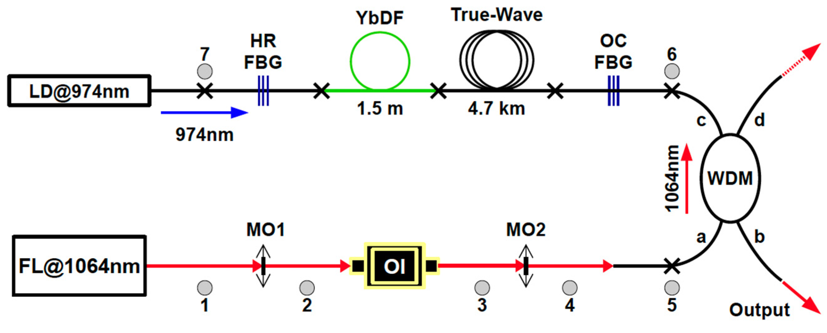
Figure 2.
First Stokes signal delivered as a function of pump power when multiple levels of 974-nm signal are used to co-pump the Yb-doped section. The black curves marked with stars represent the pure Raman laser, while the red ones marked spheres are for the hybrid system.
Figure 2.
First Stokes signal delivered as a function of pump power when multiple levels of 974-nm signal are used to co-pump the Yb-doped section. The black curves marked with stars represent the pure Raman laser, while the red ones marked spheres are for the hybrid system.
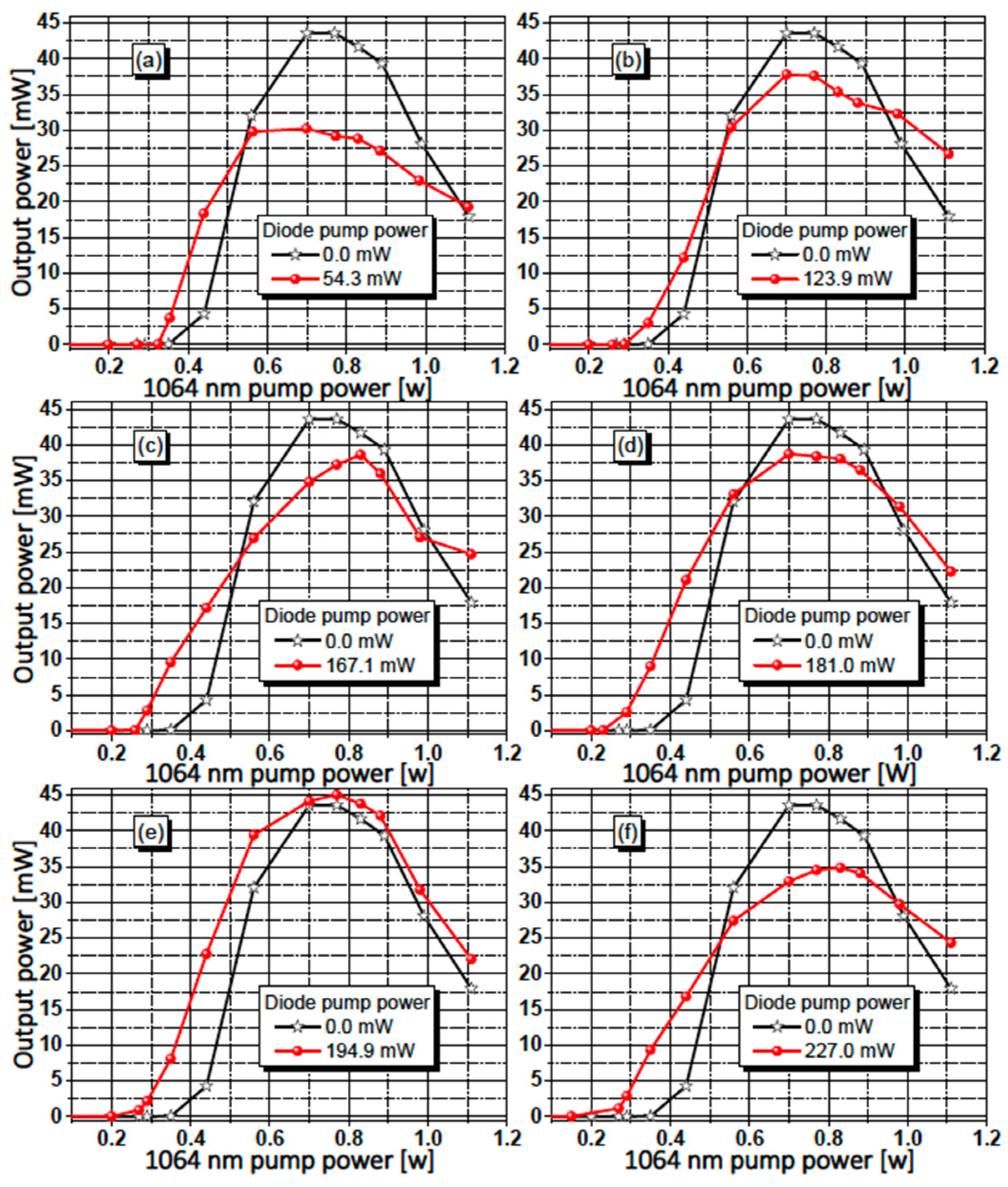
Figure 3.
Second Stokes as a function of pump when multiple levels of 974-nm signal pump the Yb-doped section. The black curves marked stars represent the pure Raman laser, the red ones with spheres are for the hybrid system.
Figure 3.
Second Stokes as a function of pump when multiple levels of 974-nm signal pump the Yb-doped section. The black curves marked stars represent the pure Raman laser, the red ones with spheres are for the hybrid system.
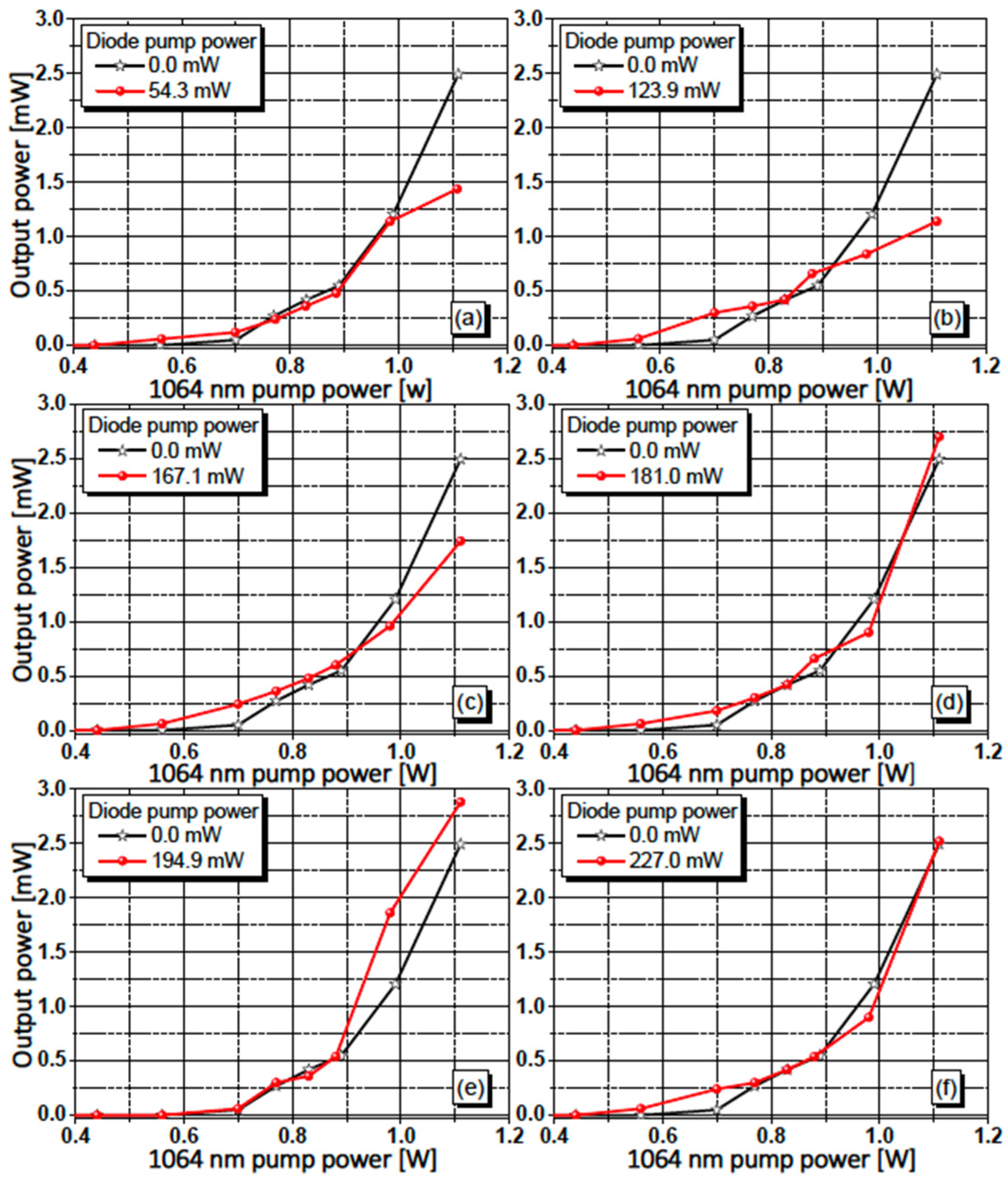
Figure 4.
(a) Pumping the Yb3+ cavity, (b) pumping (below threshold) the Raman cavity and (c) Simultaneous pumping as hybrid system.
Figure 4.
(a) Pumping the Yb3+ cavity, (b) pumping (below threshold) the Raman cavity and (c) Simultaneous pumping as hybrid system.
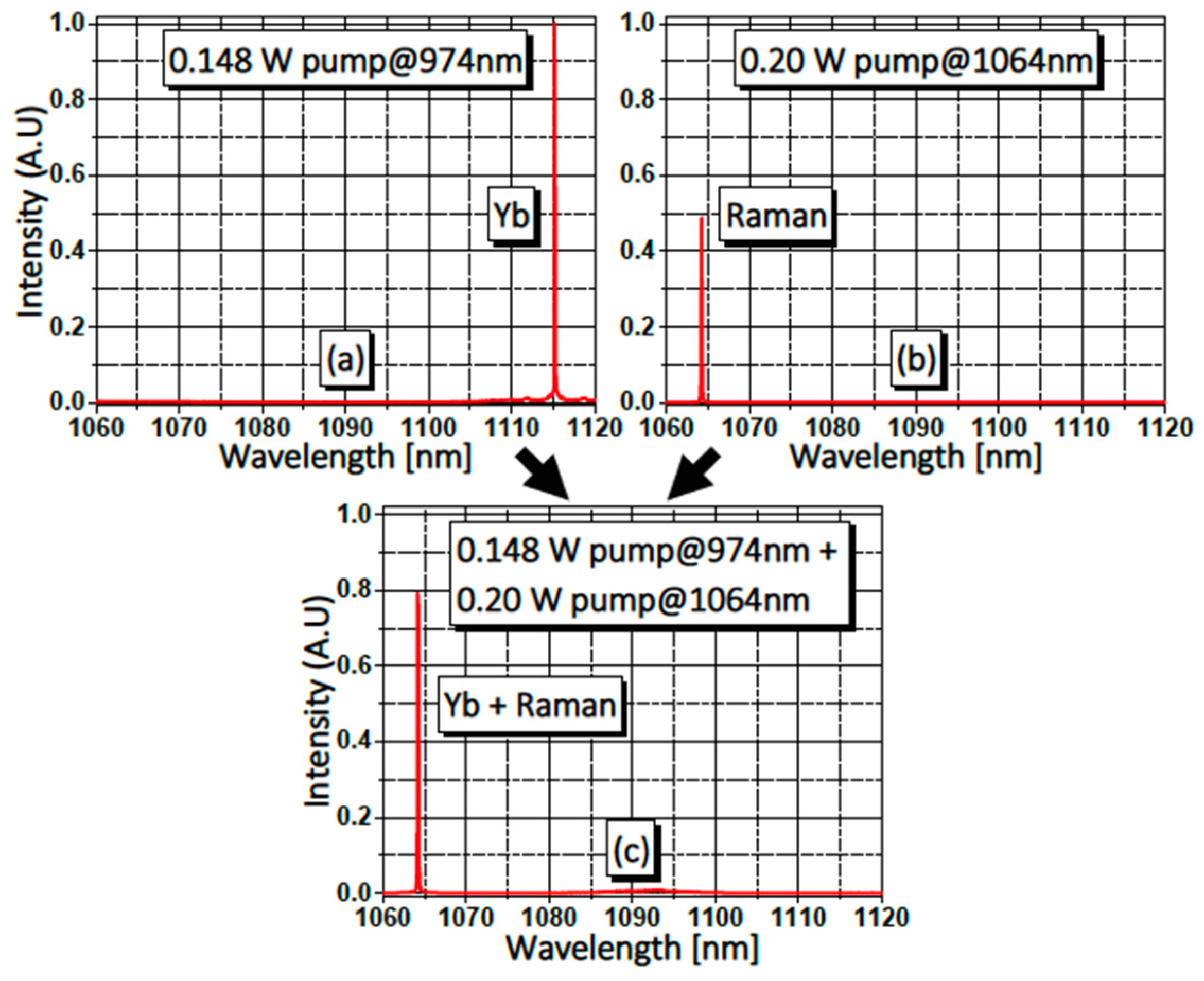
Figure 5.
(a) Pumping the Yb3+ cavity, (b) Pumping the pure Raman cavity below its oscillation threshold, and (c) Simultaneous pumping as a hybrid system.
Figure 5.
(a) Pumping the Yb3+ cavity, (b) Pumping the pure Raman cavity below its oscillation threshold, and (c) Simultaneous pumping as a hybrid system.
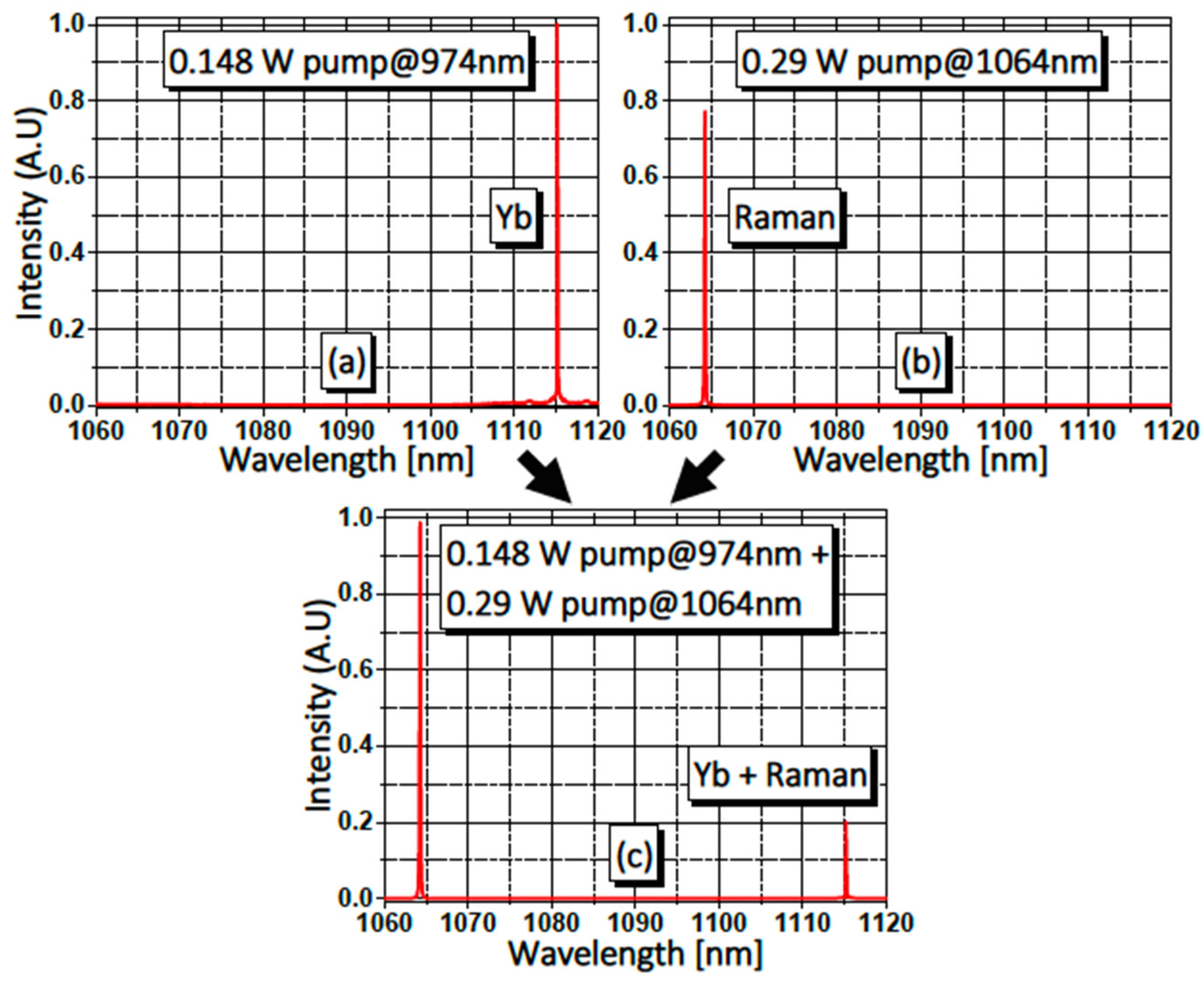
Figure 6.
Characterization of the system operating as a Yb-Doped Fiber Laser with co-pumping using moderate levels of the 1064-nm signal.
Figure 6.
Characterization of the system operating as a Yb-Doped Fiber Laser with co-pumping using moderate levels of the 1064-nm signal.
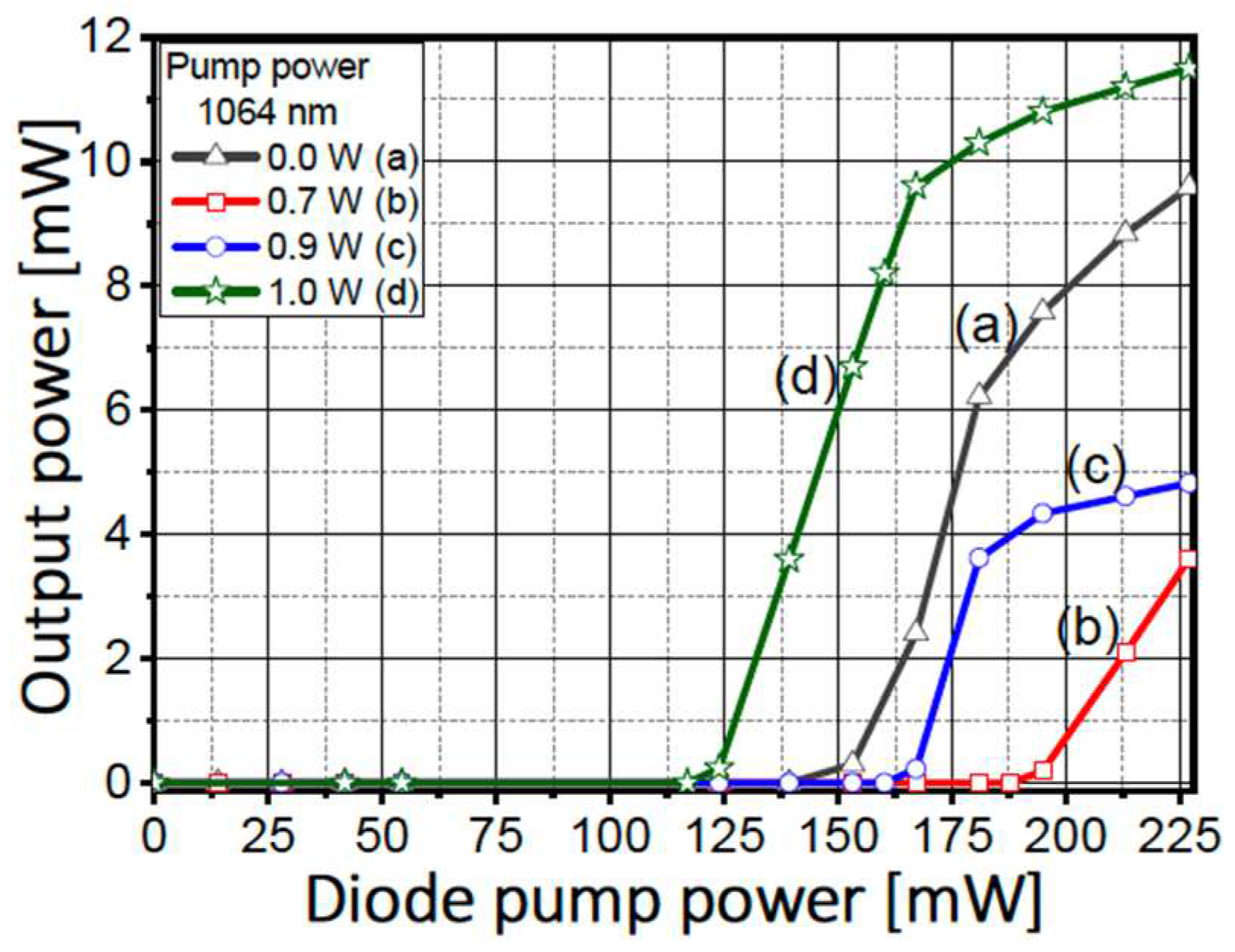
Figure 7.
Characterization of system as 1115-nm emitting Yb-doped fiber laser with co-pumping with several levels of 1064-nm signal.
Figure 7.
Characterization of system as 1115-nm emitting Yb-doped fiber laser with co-pumping with several levels of 1064-nm signal.
Disclaimer/Publisher’s Note: The statements, opinions and data contained in all publications are solely those of the individual author(s) and contributor(s) and not of MDPI and/or the editor(s). MDPI and/or the editor(s) disclaim responsibility for any injury to people or property resulting from any ideas, methods, instructions or products referred to in the content. |
© 2023 by the authors. Licensee MDPI, Basel, Switzerland. This article is an open access article distributed under the terms and conditions of the Creative Commons Attribution (CC BY) license (https://creativecommons.org/licenses/by/4.0/).
Copyright: This open access article is published under a Creative Commons CC BY 4.0 license, which permit the free download, distribution, and reuse, provided that the author and preprint are cited in any reuse.


