Submitted:
29 September 2025
Posted:
30 September 2025
You are already at the latest version
Abstract
This paper deals with the mechanical design and kinematic analysis of an autonomous wrist for space assembly (AWSA) whose actuators are activated by DC motors and ball screw drives. This robotic wrist was developed and built as a prototype to investigate in-space robotic operations including maintaining and repairing spacecraft of the US National Aeronautics and Space Administration (NASA) such as the International Space Station (ISS) or satellites. Parallel structure instead of serial structure was selected for the design of the AWSA due to several advantages it has over a serial robot manipulator (SRM), including higher payload, greater stiffness and better stability. The present paper also introduces a hybrid concept for robotic space operations, which combines a SRM performing gross motion and a parallel robot manipulator (PRM) performing fine motion. It then discusses the design and construction of the DC motor actuators and ball screw drives and presents the kinematic equations developed for the AWSA. The paper provides a closed-form solution to the inverse kinematics of the AWSA and a numerical solution using Newton-Raphson Method to its forward kinematics.
Keywords:
space operations
; international space station
; linear actuators
; kinematic analysis
; DC motors
; parallel robot manipulators
1. Introduction
Space robotics has been a very active research area in the past decade due to its potential and important applications in on-orbit servicing (OOS), which implies maintenance of space systems in orbit [1,2]. OOS operations include assembly, refueling, repair and upgrading of spacecraft after being deployed. However, NASA already recognized the importance of robotics for space operations as early as the 1980s [3,4] and considered using robot manipulators and astronauts to construct the ISS as the first step to establish permanent human presence in space [5]. In light of the potential danger astronauts could encounter while constructing the ISS in space, NASA’s intention to build the ISS sparked an intensive and controversial debate in the space community about whether or not the ISS construction should be carried out fully robotically or by an optimal balance of astronauts and autonomous robots. In the end, the ISS was built through a collaboration between astronauts and robot manipulators such as the Canadarm, well-known as the Shuttle Remote Manipulator System (SRMS) and the Canadarm2, well-known as the Space Station Remote Manipulator system (SSRMS) [6]. The SRMS and the SSRMS were used to deploy, retrieve, and maneuver large modules and other heavy pieces of equipment in the Shuttle's cargo bay or from the ISS for installation onto a location of the ISS. They were also employed to carry and position astronauts during spacewalks and to provide them with a stable working platform. On the other hand, astronauts, after being placed at a desired location by the above manipulators, carried out tasks including joining modules, installing equipment, and making crucial connections for power, data, and fluid lines, sometimes manually or with robotic assistance. In addition, astronauts inside the Space Shuttle or the ISS teleoperated the above manipulators to maneuver modules, deploy elements, and berth visiting spacecraft. NASA’s initial vision of using fully autonomous robots to construct the ISS was not realized due to the lack of advanced technology in the 1990’s for the development of sophisticated robots to perform complicated tasks required for the construction.
During the last decade, advancements in AI and related areas including smart sensors, smart materials, soft actuators, machine learning, hand exoskeleton systems and intelligent control have substantially motivated researchers to develop robot manipulators capable of autonomously performing complicated tasks for space operations without human intervention [2]. In order to be autonomous and effective, manipulators should be equipped with position and vision sensors to be aware of their locations and force sensors to effectively interact with their working environment [30]. In addition, robotic controllers should be developed to take sensor information and work in a closed-loop mode to automatically control the position and force of the manipulator to achieve the task objective. Furthermore, advanced hand exoskeleton systems [32,33,34] can be applied to master hand in a teleoperation to provide force-reflecting capability from compliant motion of the slave hand or to enhance manipulation strength of astronauts performing extravehicular activities.
Traditional robot manipulators whose joints and links are actuated in series are classified as SRM [7]. SRMs generally have long reach, large workspace and are capable of entering small spaces because of their compactness. However, their cantilever-like structure causes them to have low stiffness and consequently undesirable dynamic characteristics, especially at high speed and large payload. In addition, they have low strength-to-weight ratios due to the fact that the payload is not uniformly distributed to the actuators. Finally, the fact that relatively large position error occurs at the last link because the joint errors are accumulated throughout manipulator structure suggests that SRMs are not suitable for high precision tasks such as part assembly. On the other hand, robot manipulators whose actuators are arranged in parallel are classified as PRM and generally have relatively small workspace and low maneuverability. In return to these disadvantages, they possess high positioning capability produced by their high structural rigidity and noncumulative actuator errors. PRMs also have higher strength-to-weight ratios as compared to SRMs because the payload is proportionally distributed to the links. Finally, the inverse kinematics of PRMs has simple closed-form solutions.
Implementation of the parallel structure concept first appeared in the Stewart Platform [8] which was originally designed as an aircraft simulator. A typical Stewart Platform consists of two platforms driven by a number of parallel actuators. The invention of the Stewart platform has attracted tremendous robot designer's attention, and its mechanism was used in many robotic applications [9,24]. Dieudonne [10] and his coworkers de-rived an actuator extension transformation and presented experimental results of a Stew-art Platform-based simulator built at NASA Langley Research Center to train aircraft operators. A finite element program was used by Hoffman and McKinnon [11] to simulate the motion of the Stewart Platform whose mechanism was later applied by McCallion and Truong [12] to design an automatic assembly table. Hunt [13] conducted a systematic study of in-parallel-actuated robot arms and presented the structural kinematic problem of this type of manipulators. Sugimoto and Duffy [14] developed a general technique to describe the instantaneous link motion of a single closed-loop mechanism by employing linear algebra elements to screw systems. Kinematic problems and practical construction of the Stewart Platform were later considered by Fichter [17]. Sugimoto [18] studied kinematics and dynamics of parallel manipulators and Lee [19] derived dynamical equations for a 3 degree-of-freedom (DOF) CKC manipulator. Nguyen and Pooran [20] developed a learning control scheme for a 2 DOF CKC manipulator performing repetitive tasks.
An autonomous wrist for space assembly (AWSA) was developed and built as a prototype to investigate the feasibility of robotic assembly in space, which required the wrist to have the ability to autonomously perform fine and precise compliant motion [21]. Parallel structure instead of serial structure was selected for the design of the AWSA due to its accurate positioning capability despite its small workspace and low maneuverability, which does not pose an issue for part assembly. The AWSA with its six linear actuators driven by DC motors and ball screw drives enables an end-effector attached to it to carry out the delicate motions required for assembly tasks. The control aspect of AWSA was addressed in [26] where a decentralized adaptive control scheme was developed to successfully control the motion of the AWSA. The scope of the present paper is the implementation of the Stewart Platform [8] using linear actuators, which comprises of DC motors and ball-screw drives and are equipped with linear voltage differential transducers (LVDT) providing information of the actuator lengths for feedback control. It will focus on the mechanical design of the linear actuators and the LVDTs to meet specified payload requirements and on developing solutions for the forward and inverse kinematics of AWSA.
This paper is organized as follows. Section 2 gives an overview of robotic construction of the international space station (ISS) and Section 3 describes the main components of the AWSA and their functions. The design and component selection of the linear DC actuator for the AWSA will be presented and discussed in Section 4. Section 5 derives a closed-form solution for the AWSA inverse kinematics and provides an algorithm to obtain an iterative numerical solution for AWSA forward kinematics. Concluding the paper, Section 6 provides a summary of the paper's contents and offers future research directions.
2. Robotic Construction of the International Space Station
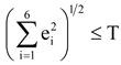
In 1984, President Reagan approved the construction of the ISS with international partners including Canada, Japan and Russia and many nations of the European Space Agency [6]. The design of the ISS took place between 1984 and 1993, and its components were built all over the US, Canada, Japan, and Europe starting in the late 1980s. The ISS, a large spacecraft orbiting the Earth at an altitude of about 248 miles with a speed of about 17,500 mph, was originally planned to be a laboratory and observatory and to serve as a low orbit staging base for future missions to the Moon and Mars. NASA planned to use the SRMS of the Space Shuttle to perform the construction of the ISS in space. While the SRMS, a serial robot manipulator, was developed to assist astronauts to deploy, retrieve, and handle big payloads in free space, (Figure 1), it was not suitable for carrying out motions needed in typical tasks of the ISS construction where the manipulator would be constantly in contact with the environment. Thus, there was a need to develop a mechanism to be mounted between the end of the SRMS and an end-effector to enable it to perform fine and precise motions while complying with the contact force generated by the environment it was in contact with. This type of compliant motion is often required in an assembly task of the construction of the ISS. Such an above idea was thought for the old Canadarm (SRMS), now retired, but now can be applied to Canadarm2 (SSRMS) which is a larger, more advanced robotic arm developed for the ISS. As a matter of fact, the above type of mechanism was already incorporated into the special-purpose robot Dextre that was integrated into the SSRMS to carry out specific tasks required for the ISS assembly and maintenance (Figure 2).
3. The Autonomous Wrist for Space Assembly (AWSA)
Based on the discussion in Section 2 about the need for the development of a robot manipulator system to perform tasks required for the construction, maintenance and repair of the ISS, Figure 3 illustrates a proposed a hybrid concept of combining a SRM with a PRM to accomplish the above tasks. One end of the SRM is connected to either a space shuttle or a location of the ISS and its other end is connected to the PRM. An end-effector (tool) is mounted to the PRM to carry out robotic tasks. With a serial structure where the manipulator links are coupled serially, the SRM has long reach and large workspace, but also suffers from severe actuator backlash making the manipulator incapable of carrying out precise motions. On the other hand, despite its small workspace, the PRM in a parallel arrangement of its actuators is capable of performing precise motions due to its low backlash and non-accumulating link errors. The proposed concept illustrated in Figure 3 considers strengths and weaknesses of the SRM and the PRM and assigns them to perform the type of motions that they are most suitable for. It is noted that in general, the PRM parameters are highly impacted by the SRM kinematics. However, in the above hybrid configuration of the SRM and PRM, after the SRM hands the task over to the PRM, the SRM configuration (position and orientation) is locked and updated by sensors either internally using manipulator joint sensors or externally using vision and proximity sensors. The updated configuration of the SRM is then provided to the control system of the PRM so that the configuration of the PRM is updated with respect to the global frame. Since after the PRM takes over the task, the configuration of the SRM cannot be changed anymore, the SRM kinematics can no longer influence the PRM configuration.
There are two types of motions a robot manipulator performs, namely, the gross motion and the fine motion [24]. While gross motion refers to the overall movements a robot manipulator makes to bring itself or an object to within its workspace, fine motion deals with precise and controlled movements required for tasks like part assembly where accuracy of position and force is essential. To carry out a particular task such as assembly of a part on the ISS, it is envisioned that the SRM performs the gross motion autonomously or by teleoperation to move the end-effector into the workspace of the PRM. During the gross motion phase, collision avoidance strategies may be employed to avoid colliding with other structures or spacecrafts around the workspace. After the SRM finishes its gross motion, it renders motion control to the PRM that then carries out the fine motion to complete the assembly task. Since the end-effector will be constantly in contact with the structure of the ISS, compliant motion control may be employed to avoid damage to the end-effector and the ISS structure by excessive contact forces and torques.
Figure 4 shows a prototype of the PRM, named AWSA that was designed and built to study the feasibility of using parallel robot manipulators for in-space robotic operations including maintaining and repairing NASA spacecrafts including the ISS or satellites [21]. The wrist is composed of two platforms, the Tool Platform (TP) and the Robot Platform (RP). Referring to Figure 3, an end-effector is connected to the TP of the AWSA via a force sensor and one end of the SRM is connected to the RP of the AWSA. As shown in Figure 4, the TP is coupled to the RP through six links. Each link constitutes a linear actuator comprising a DC motor and a linear ball screw drive. The ends of the links are connected to the TP and RP through ball joints. The AWSA possesses six degrees of freedom because it has six linear actuators coupled together in a parallel structure through the TP and RP. The linear actuators are equipped with LVDTs that measure the actuator lengths and provide them for joint position feedback control.
As its name implies, AWSA is intended for autonomous operations using position and force feedback from LVDTs and force sensors. A control system can be developed to provide AWSA with positioning and force control capability to carry out space assembly tasks autonomously. However, for complex tasks in inaccessible and high-risk space environments, AWSA can be used in a teleoperation in which a wearable hand exoskeleton [32,33] is employed in the master hand so that the maser hand exoskeleton captures the motion of human fingers and reproduce the contact force between AWSA and its holding object [34].
4. The Linear DC Motor Actuator
Figure 5 shows the details of the linear actuator of the AWSA, which is mainly composed of a DC motor and a ball joint drive comprising a ball screw and a ball nut. An LVDT is mounted along the length of the actuator to acquire its length for feedback control.
We now discuss the design and selection of the linear actuator components that are divided into two categories, the structural components, and the dynamic components. The structural components are the main load bearing components responsible for holding the actuator together. The dynamic components are those providing the actuator with movement capability and thus comprise the DC motor, the ball joint drive and the LVDT. In order to minimize costs and system downtime, parts of the above components are selected to be off-the-shelf items. The ball screw is selected by considering its maximum lead, that is calculated by [22]
where and are the desired actuator resolution and maximum resolution of the motor, respectively. The minimum lead can be calculated by
where and are the desired maximum linear velocity and the assumed maximum rotational velocity of the selected motor, respectively. It is important to select a ball screw whose lead lies within the range of lead specified by and . The maximum allowable rotational velocity of the ball screw must be calculated to assure that its resonant frequency is greater than the operating frequency, namely
where f is the coefficient specified by the ball screw mounting method, d is the inside diameter of the screw and L is the length of the screw. We also are aware that the above range satisfies only the motion requirements of the ball screw but does not dictate the behavior of the ball screw as a load bearing element. The maximum axial load for the selected ball screw can be determined by
where m is a coefficient determined by the way the ball screw is supported. Now based on Equations (1)-(4), a suitable ball screw can be properly selected. If a motor is not available for the selected ball screw, the above process of ball screw selection must be repeated with some different ball screw parameters until a ball screw can be selected for an existing motor.
The motor selection is performed with a compromise between size, weight, torque and speed. The selected motor should have a maximum operating rotational velocity to allow the actuator to travel at the desired linear velocity by the selected ball screw. However, the selected motor should have a resolution to achieve the desired actuator resolution . The lifting capacity of the selected motor is determined by its average operating torque, that is given by
where denotes the maximum reaction load of the AWSA, L, the lead of the selected ball screw and k (=5.654), the product of the unit conversion factor and the efficiency factor of the ball screw.
Although a motor may be capable of supplying ample torque to sustain a load, it may not be able to supply the torque at the desired speed. Therefore, the Torque-Speed curve of the selected motor must be analyzed to determine if the selected motor can provide the required torque. However, if the Torque-Speed curve is not available, the delivered torque at a specific rotational velocity can be computed by
where denotes the motor’s torque constant; , the motor’s terminal voltage; , the motor’s back EMF; , the motor’s viscous damping constant; , the motor’s terminal resistance and , the average frictional torque of the motor.
Using Equation (6), the deliverable torque at a given rotational velocity for a specific motor can be calculated. However, to determine if a motor has the minimum power to sustain at a given velocity, we use
Based on specifications expressed by Equations (1)-(7), the PMI motor, model SM6HI and NSK Ball Screw with a 2.5mm lead and 10mm diameter are selected. The motor is hard coupled to the ball screw to reduce vibration.
The LVDT size should be selected to minimize the chance of colliding with the linear actuator or the TP and the RP during the movement of the AWSA. The selected LVDT should have a resolution which is equal or smaller than that of the linear actuator. Furthermore, the LVDT traverse velocity, defined as the maximum allowable speed of retraction or extension of LVDT should be equal or greater than the actuator’s maximum velocity. Finally, the LVDT should be insensitive to mechanical vibrations and electromagnetic interferences due to its planned mounting on the motor housing. Based on the above specifications, the BALLUFF LDT, Series BTL with a resolution of 0.003 inches, a maximum traverse velocity of 13 inches/sec and output voltage range of 0-10 volts, is selected.
5. Kinematic Analysis of the AWSA
This section derives the solutions for the forward kinematics and inverse kinematics of the AWSA.
5.1. The AWSA Inverse Kinematics
Figure 6 shows the frame assignment of the AWSA. To represent the configuration (position and orientation) of the TP with respect to the RP, Frame {B} whose origin is at the centroid of the RP and Frame {A} whose origin is at the centroid of the TP are assigned as seen in Figure 6. The assignment of the above frames follows the right-hand rule. Points Ai and points Bi are the attachment points of actuator i to the TP and RP, respectively. In addition, each pair of ball joints on the platforms is distributed symmetrically with a separation angle of 120 degrees.
Referring to the vector diagram in Figure 7, the fixed position vectors , describe the position of the ball joints at , with reference Frame {A} and Frame {B}, respectively. The radii of the TP and RP are denoted by and , respectively.
In Figure 8, let represent the angle between ball joints and , which is the same between and , and and . Furthermore, if the angle between and -axis is denoted by then the position vector is computed by the following:
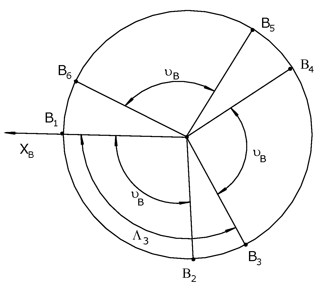
Similarly, if the angle between and -axis is denoted by as seen in Figure 9, then the position vector is given by the following:
The angles and are determined by the following:
The kinematic equations can be derived from the vector diagram for each actuator in Figure 7. The length vector , expressing the vector with respect to frame {B}, can be computed as follows:
where vector represents the coordinates of point with respect to frame {B}. Vector denoting the position of point A with respect to frame {B} is given by the following:
where x, y, and z are the Cartesian coordinates of point A in frame {B}. If the orientation of the moving frame {A} with respect to the base frame is specified by Z-Y-X Euler angles , then the corresponding Euler angle orientation matrix can be computed as follows:
Now vector can be computed as follows:
Substituting (15) into (12) yields the following:
Using (16), vector can be solved for a desired Cartesian configuration of the moving platform, specified by x, y, z, as follows:
where are the elements of the orientation matrix given by (14). After solving for vector , the square of the required corresponding length of the ith actuator, qi can be computed by the following:
Substituting (17) into (18) yields
Now in light of (20)-(22), (19) becomes the following:
where is the length of Actuator i. We recognize that Equation (23) provides a closed-form solution to the AWSA inverse kinematics. In other words, if a set of actuator lengths , , , , , and must be determined to yield a desired configuration of the TP with respect to the RP, expressed by the desired position in Equation (13) in terms of Cartesian variables x, y and z and by the desired orientation in Equation (14) in terms of the elements of the orientation matrix , then Equation (23) can be employed to accomplish this objective.
5.2. The AWSA Forward Kinematics
The forward kinematics of the above AWSA deals with the determination of the Cartesian configuration of the TP with respect to the RP, specified by Cartesian positions x, y, z and the Z-Y-X Euler angles based on the actuator lengths. Unfortunately, Equation (23) provides six nonlinear simultaneous equations with six unknowns that lead to no closed-form solutions for the forward kinematic problem. As a result, this problem is extremely difficult and needs to be solved by using iterative numerical methods such as the Newton-Raphson Method [10]. The Newton-Raphson Method first defines a function of the unknowns including x, y, z, where = (x y z )T so that . The function can be written as
It then iteratively applies the following formula
where , the error vector at the kth iteration is computed as
where J, he Jacobian Matrix of can be determined by
until certain acceptable accuracy is achieved.
The function for i=1,2…,6 in (24) can be obtained by considering (23) so that
In summary, the solution of the AWSA forward kinematics can be obtained by employing the following algorithm.
Algorithm 1- AWSA Forward Kinematics Solution Using Newton-Raphson Method
Step 1: Choose an initial guess .
Step 2: Compute for i=1,2,…,6 using (28).
Step 3: Compute using (27).
Step 4: Compute a new guess using (25).
Step 5: Repeat Steps 1 to 4 until the error between the current and previous guesses as computed by (26) is smaller than a specified tolerance value T such that
After applying the above algorithm for several test cases, we have the following remarks:
- In Step 1, if the initial guess is very far away from the true solution, the algorithm will need a considerable number of iterations before convergence or sometimes does not converge at all. Unfortunately, there is no general way to select an initial guess to ensure convergence.
- In Equations (25) and (26), an initial guess should be selected so that the inverse of the Jacobian matrix exists, which requires that det) is nonzero. If this condition is not satisfied, then we face the singularity problem. In this case, a different initial guess should be selected to avoid singularity.
- In general, the Newton-Raphson method being an iterative method is computationally intensive and is thus not suitable for real-time application. However, it could be used in computer simulation studies for control performance evaluation and for visualization of joint space variables in Cartesian space.
6. Conclusions
This paper considered the mechanical design and kinematic analysis of a robotic wrist, named AWSA that was designed and built to study the feasibility of using autonomous robot manipulators to perform precise motion required by assembly tasks in space. Parallel structure was selected in the development of AWSA because this structure had better positioning capability than its counterpart, the serial structure. AWSA comprised six linear actuators each of which consisted of a DC motor and a ball screw drive. The paper presented the mechanical design of various components of AWSA including the DC linear actuators and the LVDTs, etc., and explained their hardware selections. In addition, it derived a closed-form solution for the inverse kinematics of the AWSA and a numerical solution for its forward kinematics using Newton-Raphson method. It also introduced a hybrid concept for robotic space operations combining a SRM performing gross motion and a PRM like AWSA performing fine and precise motion required by space operation tasks.
Future work on AWSA is recommended as follows.
- Computer simulation and experiments should be conducted to obtain the reachable and dexterous workspaces of AWSA to assess the type of assembly it is suitable for.
- AWSA should be considered for other industrial and medical applications such as force-reflecting hand controller for space teleoperation, patient training device for medical physical therapy and microgravity hand trainer for astronauts.
Author Contributions
Conceptualization, C.C.N.; methodology, C.C.N., H.T.T.N. and T.T.C.D; software, H.T.T.N., T.T.C.D. and A.N.; validation, C.C.N., H.T.T.N., T.T.C.D. and A.N.; formal analysis, C.C.N., H.T.T.N., T.T.C.D.; investigation, C.C.N., H.T.T.N., T.T.C.D.; resources, C.C.N.; data curation, C.C.N., H.T.T.N., T.T.C.D. and A.N. ; writing—original draft preparation, C.C.N.; writing—review and editing, C.C.N., H.T.T.N. and T.T.C.D.; visualization, H.T.T.N., T.T.C.D. and A.N.; supervision, C.C.N.; project administration, C.C.N. All authors have read and agreed to the published version of the manuscript.
Funding
This research received no external funding.
Data Availability Statement
The original contributions presented in this study are included in the article. Further inquiries can be directed to the corresponding author.
Acknowledgments
The authors have reviewed and edited the output and take full responsibility for the content of this publication.”
Conflicts of Interest
All authors announce that they have no conflicts of interest in relation to the publication of this article.
Abbreviations
The following abbreviations are used in this manuscript:
| ISS | International Space Station |
| AWSA SRM |
Autonomous Wrist for Space Assembly Serial Robot Manipulator |
| PRM | Parallel Robot Manipulator |
| SRMS SSRMS |
Shuttle Remote Manipulator System Space Station Remote Manipulation System |
References
- Flores-Abad, A.; Ma, O.; Pham, K.; Ulrich, S. A review of space robotics technologies for on-orbit servicing. Progress in Aerospace Sciences, 2014, 68, 1-26. [CrossRef]
- Fallahiarezoodar, N.; Zhu, Z.H. Review of autonomous space robotic manipulators for on-orbit servicing and active debris removal. Space: Science & Technology, 2025, 5, Article ID: 0291. [CrossRef]
- Miller, R.; Minsky, M.; Smith, D. Space applications of automation, robotics and machine intelligence systems (ARAMIS). NASA Technical Report. 1982, NASA-CR162079.
- Dubowsky, S. Advanced methods for the dynamic control of high performance robotic devices and manipulators with potential for applications in space. NASA Technical Report. 1987, NASA-CR-181061.
- Hinkal, S.W.; Andary, J.F.; Watzin, J.G.; Provost, D.E. The flight telerobotic servicer (FTS): A focus for automation and robotics on the space station. Acta Astronautica, 1988, 17, 759-786. [CrossRef]
- Delucas, L.J. International space station. Acta Astronautica, 1996, 38, 613-619.
- Merlet, J.P. Parallel Robots; Springer Science & Business Media: Berlin, Germany, 2006; Volume 128.
- Stewart, D. A Platform with Six Degrees of Freedom Proc. Inst. Mech. Eng. 1965, 180, 371–386.
- Dasgupta, B.; Mruthyunjaya, T.S. The Stewart platform manipulator: A review. Mech. Mach. Theory 2000, 35, 15–40. [CrossRef]
- Dieudonne, J.E. An actuator extension transformation for a motion simulator and an inverse transformation applying Newton-Raphson's method. NASA Technical Report, 1972, NASA-D-7067.
- Hoffman, R.; McKinnon, M.C. Vibration modes of an aircraft simulator motion system. In Proceedings of The Fifth World Congress for the Theory of Machines and Mechanisms, USA, 1979.
- McCallion, H.; Truong, P.D. The analysis of a six-segree-of-freedom work station for mechanised sssembly. In Proceedings of The Fifth World Congress for the Theory of Machines and Mechanisms, USA, 1979.
- Hunt, K. H. Kinematic Geometry of Mechanisms, Oxford University: London, 1978.
- Sugimoto, K.; Duffy, J. Application of linear algebra to screw systems. Mech.Mach. Theory, 1982, 17, 73-83. [CrossRef]
- Hunt, K. H. Structural kinematics of in-parallel-actuated robot arms. Trans. ASME, J. Mech., Transmis., Automa. in Des., 1983, 105, 705-712. [CrossRef]
- Nguyen, C.C.’ Pooran, F.J.; Premack, T. Control of robot manipulator compliance. In Recent Trends in Robotics: Modeling, Control and Education, 1st ed.; Jamshidi, M., Luh, J.Y.S., Shahipoor, M., Eds.; North Holland: New York, USA, 1986; Volume 1, pp. 237-242.
- Fichter, E.F. A Stewart platform-based manipulator: general theory and practical construction. Int. Journal of Robotics Research, 1986, 5, 157-182. [CrossRef]
- Sugimoto, K. Kinematic and dynamic analysis of parallel manipulators by means of motor algebra. ASME Journal of Mechanisms, Transmissions, and Automation in Design. 1986, 109, pp. 1-5. [CrossRef]
- Lee, K. M.; Chao, A.; Shah, D. K. A three degrees of freedom in-parallel actuated manipulator. In proceedings of IASTED Int. Conf., 10 December, 1986.
- Nguyen, C.C.; Pooran, F.J. Learning-based control of a closed-kinematic chain robot end-effector performing repetitive tasks. International Journal of Microcomputer Applications, 1990, 9, 9-15.
- Nguyen, T.T. Intelligent Control of Closed-Kinematic Chain Robot Manipulators. Ph.D. Dissertation, The Catholic University of America, Washington, DC, USA, 2020.
- Smith, W.F.; Nguyen, C.C. On the mechanical design of a Stewart platform-based robotic end-effector. In IEEE Proceedings of the SOUTHEASTCON '91, Williamsburg, VA, USA, 7 April, 1991.
- Nguyen, C.C., Pooran, F.J., "Adaptive Force/Position Control of Robot Manipulators with Closed-Kinematic Chain Mechanism. In Recent Trends in Robotics: Modeling, Control and Education, 1st ed.; Jamshidi, M., Eds.; ASME Press: New York, USA, 1988; Volume 1, pp. 177-186.
- Behi, F. Kinematic analysis for a six-degree-of-freedom 3-PRPS parallel mechanism. IEEE Journal of Robotics and Automation, 1988, 5, 561-565. [CrossRef]
- Fu, K.S.; Gonzalez, R.C.; Lee, C.S.G. Robotics: Control, Sensing, Vision, and Intelligence, 1st Ed. McGraw-Hill: New York, USA, 1987.
- Nguyen, C.C; Zhou, Z.; Antrazi, S.S.; Campbell, C.E. Efficient computation of forward kinematics and Jacobian matrix of a Stewart platform-based manipulator. In Proceedings of the IEEE Proc. SOUTHEASTCON '91, USA, 1991.
- Nguyen, T. T.; Nguyen, C. C.; Nguyen, M. T; Duong, T. C. T.; Ngo, T. T. H.; Lu, S.; Decentralized adaptive control of closed-kinematic chain mechanism manipulator. Machines 2025, 13, 331.
- Duong, T.T.C.; Nguyen, C.C.; Tran, T.D. Synchronization Sliding Mode Control of Closed-Kinematic Chain Robot Manipulators with Time-Delay Estimation. Appl. Sci. 2022, 12, 5527. [CrossRef]
- Nguyen, C.C.; Nguyen, T. T.; Duong, T. C.; Nguyen, M. T; Ngo, T. T. H.; Lu, S. Real-time experiments for decentralized adaptive synchronized motion control of a closed-kinematic chain mechanism robot manipulator. Machines 2025, 13, 652.
- Duong, T.T.C.; Nguyen, C.C.; Tran, T.D. Experimental investigation of motion control of a closed-kinematic chain robot manipulator using synchronization sliding mode method with time delay estimation. Appl. Sci. 2025, 15, 5206. [CrossRef]
- Seraji, H. Decentralized adaptive control of manipulators: Theory, simulation, and experimentation. IEEE Trans. Robot. Autom. 1989, 5, 183. [CrossRef]
- Awan, Z.S.; Ali, K.; Iqbal, J.; Mehmood, A. Adaptive backstepping based sensor and actuator fault tolerant control of a manipulator. J. Electr. Eng. Technol 2019, 14, 2497. [CrossRef]
- Iqbal, J., Tsagarakis, N.G.; Caldwell, D. G. A multi-DOF robotic exoskeleton interface for hand motion assistance. Annu Int Conf IEEE Eng Med Biol Soc 2011. 2011, 1575.
- Iqbal, J.; Ahmad, O.; Malik, A. HEXOSYS II - towards realization of light mass robotics for the hand. 2011 IEEE 14th International Multitopic Conference, 2011, 115.
- Iqbal, J.; Tsagarakis, N. G.; Caldwell, D. G. Human hand compatible underactuated exoskeleton robotic system. Electronics letters, 2014, 50, 494. [CrossRef]
- Wei, W.; Zhou, B.; Fan, B; et al. An adaptive hand exoskeleton for teleoperation system. Chin. J. Mech. Eng., 2023, 36, 60. [CrossRef]
Figure 1.
The Shuttle Remote Manipulator System (SRMS). (Source: https://images.nasa.gov/).
Figure 1.
The Shuttle Remote Manipulator System (SRMS). (Source: https://images.nasa.gov/).
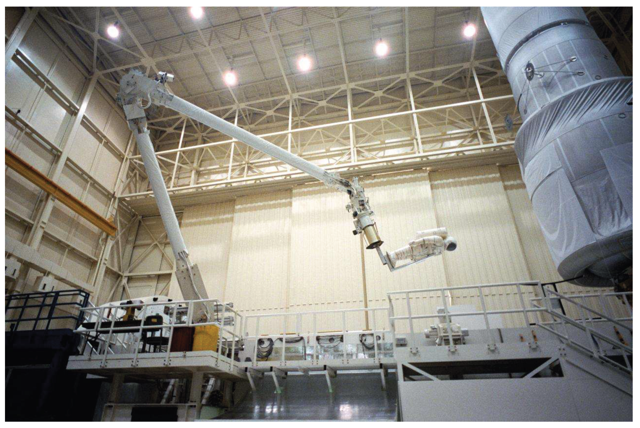
Figure 2.
The Canadarm2 (SSRMS) and special-purpose robot Dextre. (Source: https://images.nasa.gov/).
Figure 2.
The Canadarm2 (SSRMS) and special-purpose robot Dextre. (Source: https://images.nasa.gov/).
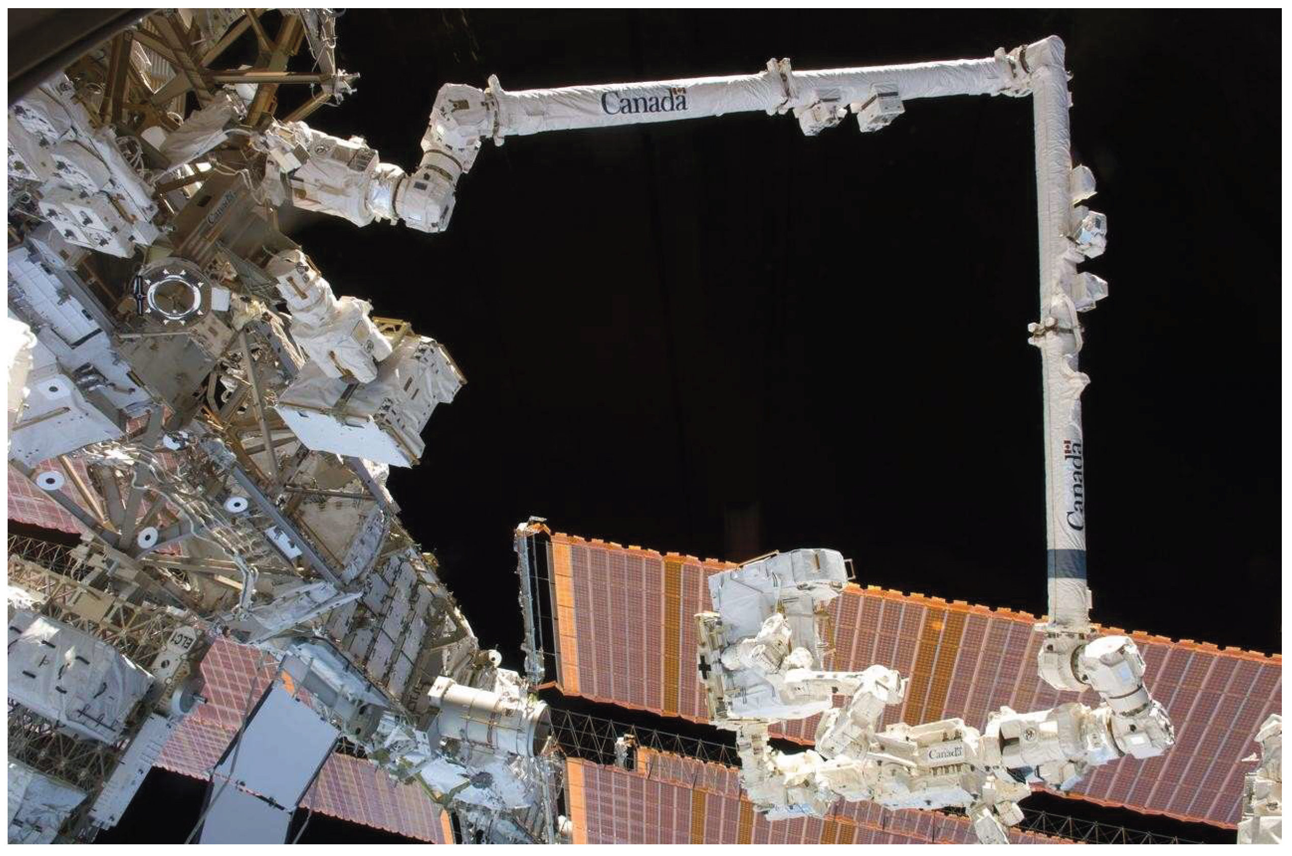
Figure 3.
Concept of combining SRM with PRM for in-space robotic operations.
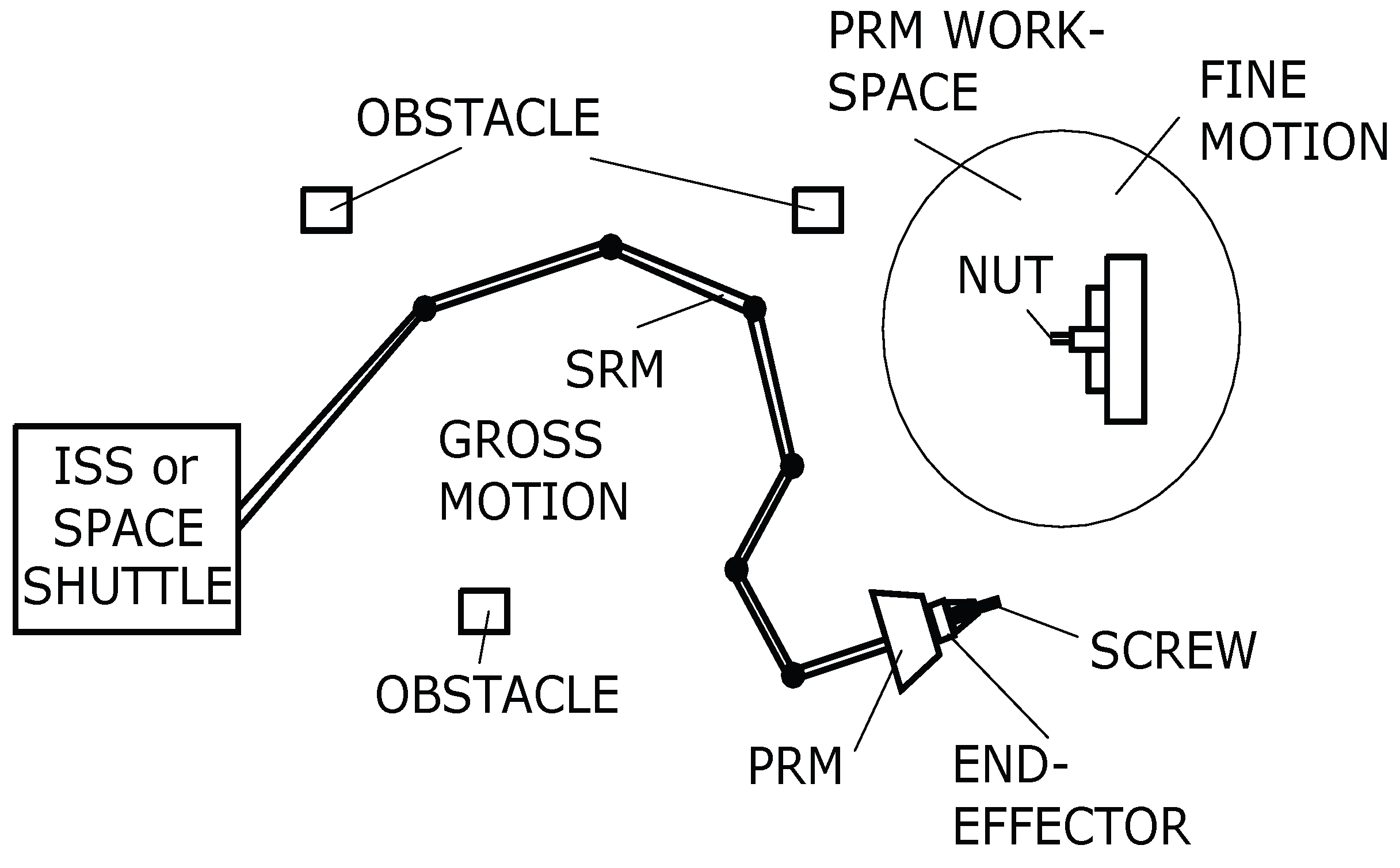
Figure 4.
The autonomous wrist for space assembly (AWSA).
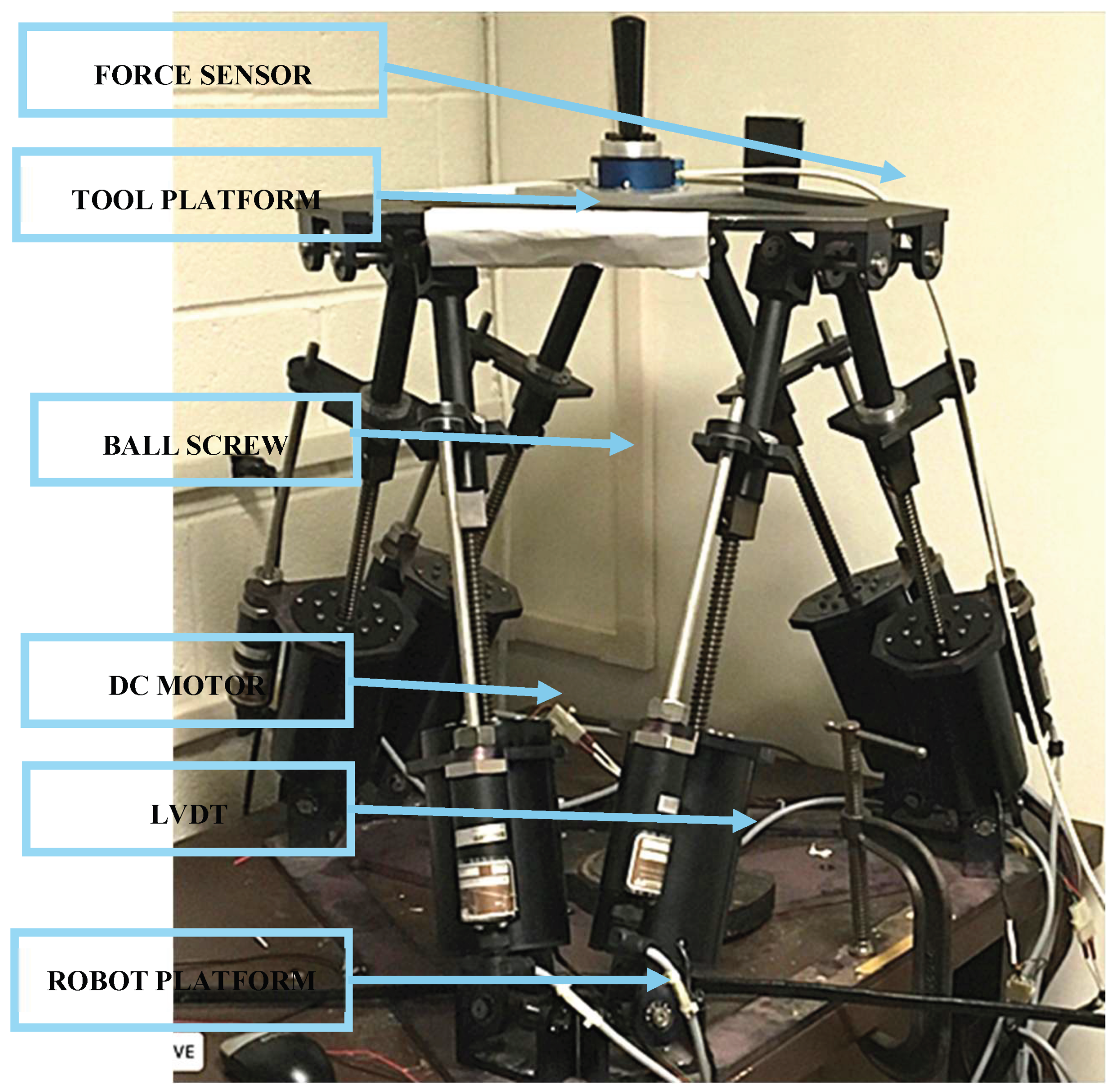
Figure 5.
The linear DC motor actuator.
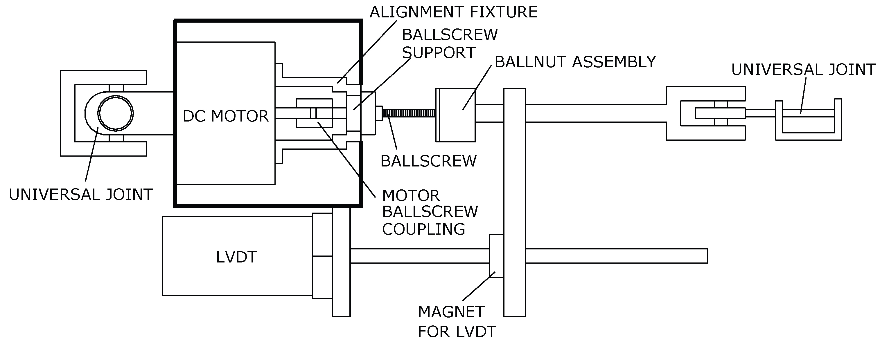
Figure 6.
Frame assignment of AWSA.
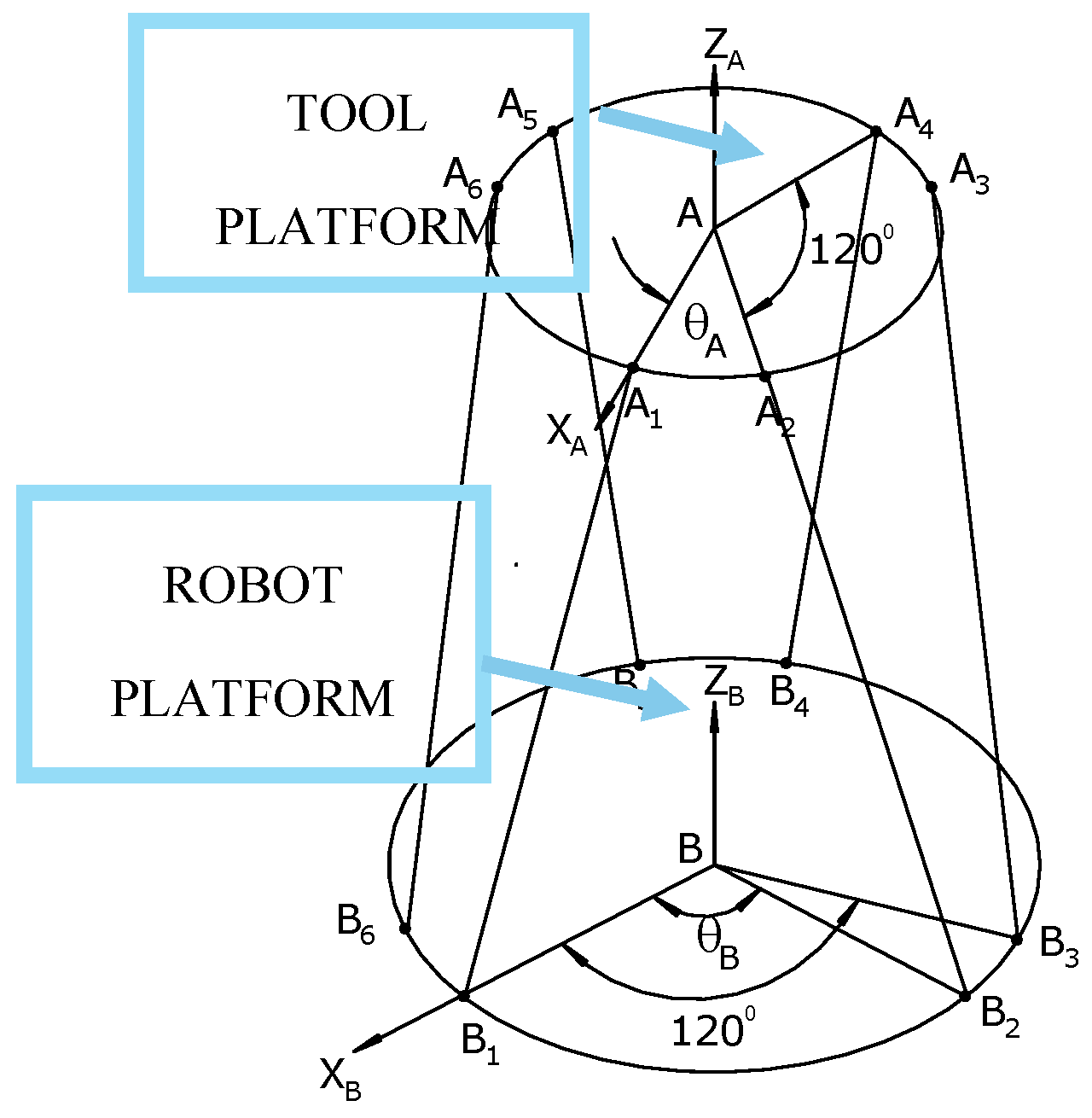
Figure 7.
Vector diagram of AWSA.
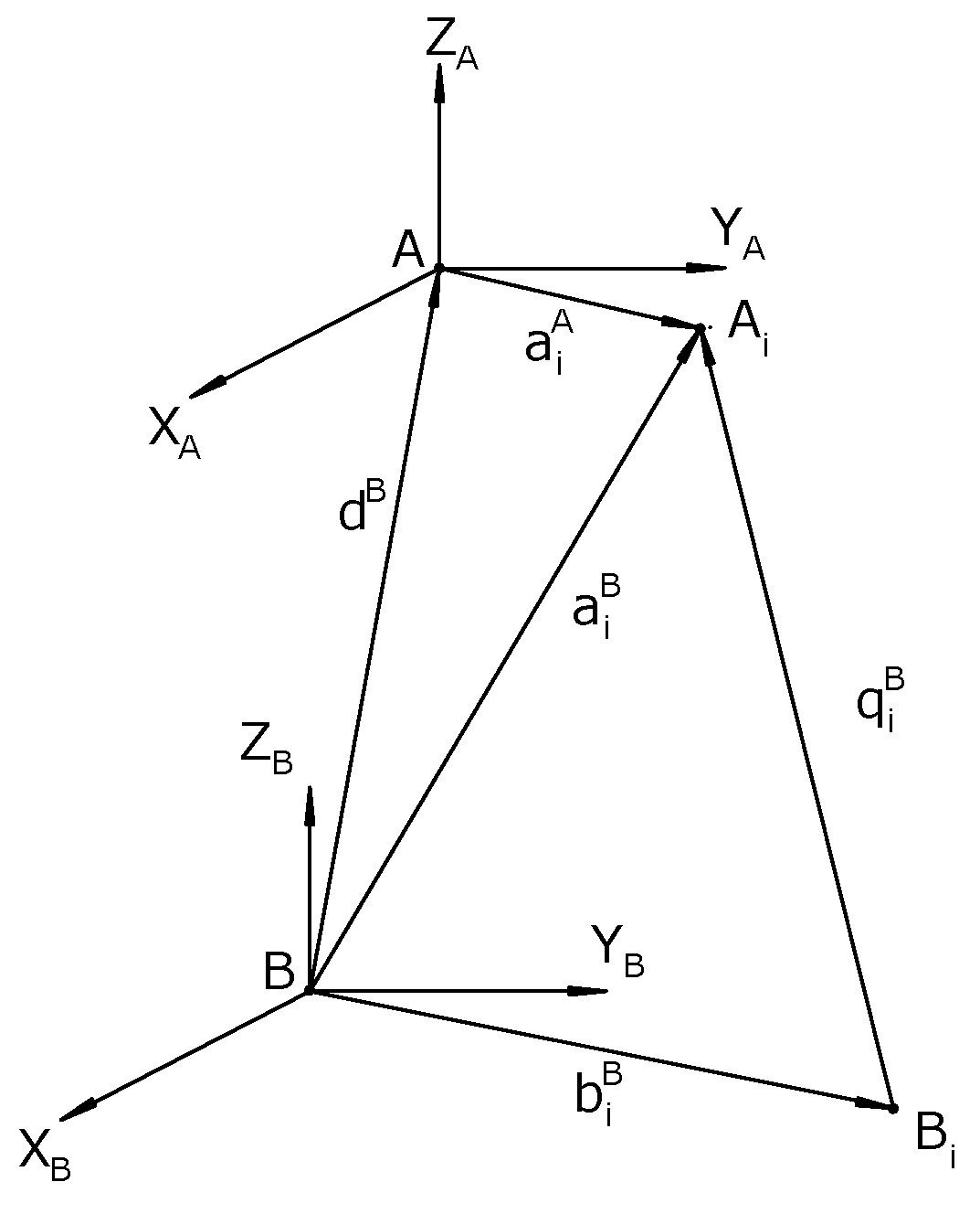
Figure 8.
Position of ball joints with respect to the -axis.
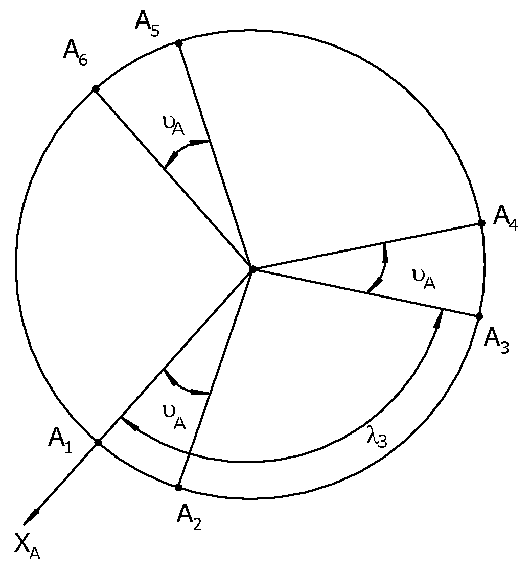
Figure 9.
Position of ball joints with respect to the -axis.
Disclaimer/Publisher’s Note: The statements, opinions and data contained in all publications are solely those of the individual author(s) and contributor(s) and not of MDPI and/or the editor(s). MDPI and/or the editor(s) disclaim responsibility for any injury to people or property resulting from any ideas, methods, instructions or products referred to in the content. |
© 2025 by the authors. Licensee MDPI, Basel, Switzerland. This article is an open access article distributed under the terms and conditions of the Creative Commons Attribution (CC BY) license (http://creativecommons.org/licenses/by/4.0/).
Copyright: This open access article is published under a Creative Commons CC BY 4.0 license, which permit the free download, distribution, and reuse, provided that the author and preprint are cited in any reuse.


