
Submitted:
23 September 2025
Posted:
24 September 2025
You are already at the latest version
Abstract
Simulating damage phenomena in masonry structures remains a significant challenge because of the intricate and heterogeneous nature of this material. An accurate evaluation of fracture behavior is essential for assessing the bearing capacity of these structures, thereby mitigating dramatic failures. This paper proposes an innovative adaptive concurrent multiscale model for the failure analysis of masonry structures under in-plane loading conditions. Developed within a Finite Element (FE) framework, the proposed model employs a domain decomposition scheme to solve a combination of fine- and coarse-scale sub-models concurrently. In regions requiring less detail, the masonry is represented by homogeneous linear elastic macro-elements. The material properties for these macro-elements are derived through a first-order computational homogenization strategy. Conversely, in areas with higher resolution needs, the masonry is modeled as a heterogeneous material, accurately depicting individual brick units and mortar joints. To capture strain localization effectively in these finer regions, a Phase Field Cohesive Zone Model (PF-CZM) formulation is employed as the fracture model. The adaptive nature derives from the fact that at the beginning of the analysis, the model is entirely composed of coarse regions. As nonlinear phenomena start to develop, these regions are progressively deactivated and replaced by fine regions. An activation criterion detects damage-prone portions of the domain, thus triggering the transition from macro to micro scales. The validity of the proposed model is assessed through multiscale numerical simulations on a specific case study, with the results compared to those from a direct numerical simulation. The results confirm the effectiveness and accuracy of this innovative approach for analyzing masonry failure.
Keywords:
phase-field cohesive zone model
; finite element method
; concurrent multiscale model
; crack propagation analysis
; masonry
1. Introduction
Masonry buildings are a significant part of the world's architectural heritage, and many of these structures, especially residential ones, hold considerable cultural and historical value. Consequently, preserving and restoring them has become a key priority for promoting sustainable urban development and reducing land consumption [1,2,3].
To effectively rehabilitate these buildings, it's essential to have a thorough understanding of their structural behavior under normal and exceptional loads [4]. While masonry is effective at resisting gravitational forces, it is inherently vulnerable to lateral forces, such as those caused by earthquakes [5,6]. These seismic forces can induce severe cracking and a subsequent loss of structural integrity, often leading to partial or total collapse. To address this critical vulnerability, developing accurate and reliable analysis tools is essential for assessing these structures and creating suitable strengthening strategies [7].
In recent years, numerical methods have become a primary tool for analyzing the fracture behavior of materials [8,9,10,11,12]. They allow for the simulation of the complex mechanical behavior of materials and provide valuable insights into the initiation and propagation of cracks. However, accurately modeling masonry's behavior is a significant challenge due to its heterogeneous nature. The mechanical response of masonry material heavily depends on the properties of its constituent components—namely, brick units and mortar joints—and their arrangement. This complexity leads to anisotropic behavior, where the strength properties vary based on the load orientation [13,14]. Additionally, this anisotropy can worsen with deformation and damage, introducing further nonlinearities into the structural response.
Numerical approaches for modeling masonry are typically classified according to the scale of analysis, so that one can distinguish between micro- and macro-modeling methods [15,16].
Micro-modeling approaches represent masonry in detail at the level of its individual components, specifically the blocks or units and mortar joints [17,18]. This feature enables a comprehensive analysis of the mechanical behavior of each material constituent and its interactions, such as decohesion and friction, as well as the overall pattern of the masonry. Notable examples of micro-modeling strategies include detailed and simplified approaches. In the detailed approach [7,19], brick or block units and mortar joints are modeled using continuum elements that are interconnected by discontinuous elements, thereby effectively reproducing damage phenomena (such as decohesion) that occur at the interfaces between units and mortar. On the other hand, the simplified approach [20] represents masonry using expanded brick units modeled with continuum elements that are connected by zero-thickness interface elements. These interface elements replicate both the mechanical behavior of the mortar joint and the interaction mechanics at the brick/mortar interfaces.
While micro-modeling strategies offer better simulation of material anisotropy and a more realistic representation of strain localization and damage mechanisms under various loading conditions, they have significant drawbacks. The most notable limitation is the substantial computational demand required for numerical simulations. This challenge makes it impractical to apply micro-modeling approaches to entire masonry structures, thereby restricting their use to smaller elements, such as portions of masonry buildings.
Macro-modeling approaches treat masonry as a fictitious material that is homogeneous and anisotropic, with its mechanical properties being phenomenological in nature [21]. Depending on the specific application, these models can utilize either linear or nonlinear elements. In cases where nonlinear behavior is considered, the structural response of the masonry is modeled using nonlinear frameworks based on damage continuum mechanics and/or plasticity theory. One notable advantage of these modeling approaches is their relatively low computational requirements, making them an effective means of simulating the behavior of entire masonry buildings.
However, macro-modeling approaches also have significant limitations. A major drawback is their reduced accuracy in predicting damage mechanisms and strain localization since they do not explicitly represent individual masonry components. Additionally, these models may struggle to accurately capture the anisotropic behavior of masonry, in which mechanical properties vary according to the orientation of loads in relation to the arrangement of blocks and joints. Furthermore, the calibration of model parameters to align with experimental data or field observations can be complex, time-consuming, and particularly challenging when dealing with various types of masonry that have differing properties.
In recent years, a substantial body of research has underscored the potential of multiscale modeling strategies in accurately predicting and reproducing the mechanical behavior of masonry. Multiscale approaches encompass modeling techniques that simulate the mechanical behavior of a material across various scales, integrating detailed information about material constituents at the microscopic level with the structural behavior of the entire structure at the macroscopic level [22,23].
These multiscale modeling approaches can be categorized into three primary types: (i) hierarchical models, (ii) semi-concurrent models, and (iii) concurrent models [24].
Hierarchical models follow a sequential process in which information flows in a "one-way" direction from the microscale to the macroscale [22,25,26]. In this framework, detailed analyses are executed at smaller scales, and the resultant data informs the parameters and behaviors at larger scales. These models are based on the assumptions that the scales are sufficiently distinct and that the material exhibits macroscopic homogeneity.
The implementation of such models necessitates the definition of a Representative Volume Element (RVE), for which a thorough microscopic analysis is conducted to derive the overall macroscopic constitutive law utilizing a homogenized method amenable to numerical analyses at the macroscale. Various homogenization methodologies, including those based on Cauchy or Cosserat macro-continuum theories, are applicable [27,28,29,30]. The primary advantage of hierarchical models resides in their efficiency, as computational resources are concentrated on critical aspects at each scale, rendering them less computationally demanding than alternative multiscale methods. Nevertheless, a significant limitation is the potential loss of intricate interaction effects between scales, which can compromise the accuracy of predictions related to complex coupled behaviors. Furthermore, the one-way flow of information may occasionally fail to capture essential feedback mechanisms between scales.
Semi-concurrent models utilize a "two-way" coupling between the microscopic and macroscopic scales [31,32,33]. In this design, the state variables derived from the analyses of the RVE are continuously transferred to the macroscopic model as overall stress fields and tangent operators, thereby facilitating a more precise representation of material behavior.
The principal advantage of semi-concurrent models is their ability to yield a more accurate depiction of strain localization phenomena. However, they may incur heightened computational demands and necessitate sophisticated methodologies to manage the interchange of information between scales effectively.
Concurrent models are distinguished by their simultaneous coupling of scales, wherein microscale behavior directly influences macroscale responses and vice versa throughout the entire simulation [34,35,36]. In contrast to hierarchical and semi-concurrent models that use "scale transitions," concurrent multiscale models employ "scale embedding." This means that sub-models of different scales can exist side-by-side in neighboring areas of the computational domain. As a result, any heterogeneous structural model can be broken down into fine- and coarse-scale sub-models that are solved simultaneously.
This methodology confers the advantage of accurately representing strain localization phenomena, which are typically confined to fine regions of the computational domain, while concurrently achieving significant computational efficiencies by modeling undamaged regions with coarse representations.
Numerous concurrent multiscale models have been proposed and successfully employed to assess the structural response of masonry structures. Remarkably, Greco et al. [37] developed a multiscale model for the failure analysis of periodic masonry structures subjected to in-plane loading conditions. This model incorporates a multilevel domain decomposition strategy in conjunction with an adaptive refinement technique that enhances the resolution of computational domains likely to be impacted by strain localization. Specifically, in fine regions, the masonry is represented by expanded brick units interconnected through cohesive interface elements that replicate the mechanical behavior of mortar joints and brick/mortar interfaces during failure events. In contrast, coarse regions consist of macro-elements whose constitutive response is characterized by homogenized moduli derived through a first-order computational homogenization scheme.
Driesen et al. [38] proposed a concurrent multiscale domain activation strategy for the damage analysis of large-scale masonry structures. This model adeptly integrates elastic macroscale elements with nonlinear microscale regions, where the masonry is represented using a simplified micro-model scheme consistent with expanded brick units connected by interface elements. An effective damage model for the interface is established to reproduce the expected behavior during loading accurately.
The main goal of this research is to present a new adaptive concurrent multiscale model. Built on the Finite Element Method (FEM), this model is designed to analyze the failure of periodic masonry structures under in-plane loading. Similar to the modeling strategies in [37], the proposed approach uses domain decomposition, splitting the computational domain into coarse and fine regions. The coarse regions consist of linear elastic macroscopic elements, and their overall moduli, which describe the constitutive behavior, are determined through a first-order homogenization of an RVE of the masonry. The fine regions utilize a detailed micromechanical model for masonry to accurately capture the failure mechanisms. Specifically, masonry is represented in detail as a two-phase material composed of brick units and mortar joints. To effectively reproduce the failure mechanisms, the Phase Field Cohesive Zone Model (PF-CZM) for fracture, developed by Wu et al. [39,40,41], is employed. With its ability to reproduce arbitrary crack paths in homogeneous and heterogeneous materials, this model represents one of the most powerful cohesive fracture approaches available in the literature. A key distinction of the PF-CZM from classical phase-field models lies in its fracture response, which shows an almost negligible dependence on the length scale parameter. This represents a significant improvement, as the length scale parameter strongly influences the numerical predictions of other phase-field models. In particular, the proposed model employs a hybrid isotropic/anisotropic formulation of the PF-CZM model, which is based on an appropriate crack-driving force consistent with a Drucker–Prager model featuring a compressive cap, tailored for analyzing masonry.
The transition from coarse to fine scales is managed by an activation approach, which progressively refines the areas of the computational domain where damage is anticipated. Specifically, coarse regions are deactivated, and fine regions are activated in their place to capture the development of damage.
To the best of the authors' knowledge, this work represents the first attempt to develop an adaptive concurrent multiscale approach for analyzing the failure behavior of masonry structures using the PF-CZM to replicate fracture mechanisms.
Different case studies are conducted to evaluate the reliability and efficiency of the proposed multiscale approach. Initially, the PF-CZM model for fracture is validated through comparisons with experimental and numerical results available in the literature. Following this, we focus on large-scale masonry structures. The results obtained from the proposed multiscale approach are compared to those from equivalent direct numerical simulations, which use a fully microscopic model for masonry.
2. Theoretical Background
This section details the theoretical foundation of the new adaptive concurrent multiscale model. The section begins with a detailed description of the micro- and macro-modeling approaches, which are used to represent masonry behavior in the finer and coarser regions of the computational domain, respectively. We then describe the activation criterion that controls the dynamic refinement of the domain, highlighting the importance of the first failure surface for masonry in this process.
2.1. A Detailed Micromechanical Model for Reproducing Failure Mechanisms Inside the Masonry
This section provides a comprehensive description of the micromechanical modeling strategy used to reproduce the complex failure behavior of the masonry accurately. The approach is based on a detailed representation of the material at its constituent level, effectively treating masonry as a two-phase composite material. This model explicitly accounts for the individual characteristics of the solid brick units and the mortar joints, as well as their mechanical interaction.
Without loss of generality, consider the conceptual scheme of Figure 1, which represents a two-dimensional periodic masonry structure composed of regular brick units interconnected by a network of horizontal and vertical mortar joints. This structure occupies a defined computational domain, denoted as ΩMicro, whose external boundary ∂ΩMicro is partitioned into two distinct sub-regions, and . These sub-regions are used to apply Neumann and Dirichlet boundary conditions, respectively. Precisely, external tractions are applied on , while prescribed displacements are imposed on .
A fundamental assumption of this model is that the brick units behave as linear elastic and are considered undamaged. In contrast, the mortar joints are assumed to be the primary locations of potential damage. This hypothesis is well-supported by extensive experimental evidence, which shows that the strength and fracture properties of mortar are typically significantly lower than those of the brick units. Consequently, the failure mechanisms in masonry are predominantly characterized by crack nucleation and propagation within the mortar joints, leading to a typical "staircase" crack pattern.
In this framework, the fracture mechanisms of mortar joints are simulated using the Phase Field Cohesive Zone Model (PF-CZM), a method originally introduced by Wu et al. [40]. The primary principle of the PF-CZM is to represent a sharp crack as a diffuse band of finite width, rather than as a discrete line. The extent of damage within this band is quantified using a continuous scalar field known as the unknown phase-field or damage field , which ranges from 0 to 1. In particular, =0 indicates intact material, while =1 signifies a fully damaged state.
Under quasi-static loading and small displacement assumptions, the governing equations of the solid mechanics problem can be expressed in weak forms as follows:
where, Cb and Cm are the fourth-order constitutive tensors of the brick units and mortar, respectively. Besides, is the gradient operator, f is the body force (per unit volume) vector, and u and δu represent the unknown displacement field and the virtual displacement field, respectively, defined as:
where represents the Sobolev space defined over the entire domain .
Because the mortar joints are damageable, the fourth-order constitutive tensor is expressed as follows:
In Eq. (3) represents the energy degradation function, while is the undamaged elasticity tensor of the mortar.
According to the phase field approach, the governing equation of the crack problem can be expressed in weak form as follows:
where, is the strain energy of the mortar, Gc is the critical energy release rate of the mortar and represents the crack surface density function generally defined as:
In Eq. (5), l0 is the length scale parameter that manages the width of the diffuse band reproducing the crack, while represents the so-called geometric crack function, which establishes the distribution of the crack phase-field within the band, expressed as follows:
In the proposed model, consistent with the so-called hybrid formulation [42], two different energy functions for the mortar are used to define the stress field and the damage evolution law, specifically:
so that one can write:
In particular, according to Wu et al. [40,41], this degradation function can be expressed in the following general form for cohesive cracks:
In Eq. (11), p≥2, a1>0, a2, and a3 govern the softening behavior of the material and assume the following expressions:
where, Em is the Young's modulus of the material and ft is the failure strength of the material. In addition, k0 ≤-0.5ft2/Gc and wc are the initial modulus (slope) and the limit crack opening width of the cohesive law.
Note that the term lch in Eq.(12) measures the size of fracture process zone. In addition, the parameters a2 and a3 are determined solely by the chosen softening curves. The technical literature offers various options for these curves, such as linear, exponential, hyperbolic, and Cornelissen's laws. These can be represented using the following values [42]:
Returning to Eq. (10), denotes the effective crack driving force. It is important to note that various approaches for defining this force are reported in scientific literature (see, for instance, [40,41,43]), often defined in terms of an equivalent effective stress. For the proposed model, the effective crack driving force is defined in terms of an equivalent strain , which is derived from a Drucker-Prager damage model that includes a compression cap [44]. Specifically, the following expressions for the effective crack driving force and the equivalent strain are employed:
where and represent the first invariant of the strain tensor and the second invariant of the deviatoric strain tensor, respectively, that under the assumption of plane stress conditions are defined as:
In Eq (18), is the Poisson's ration of the mortar, while A, B, C, and D are parameters defined in terms of the uniaxial tensile (), uniaxial compressive (), and biaxial compressive (generally expressed as ) that assume the following expressions:
According to the fundamental irreversibility condition that the crack phase-field must satisfy (), the effective crack driving force () is typically replaced by a history variable . This variable, which tracks the maximum value that was ever reached over the simulation, is defined as follows:
Here, is the initial value of the effective crack driving force that denotes the limit of the undamageable state, while represents the value of the crack driving force reached at time tn within the time interval [0,T].
By incorporating the expressions from the previously mentioned equations, the weak forms of the solid mechanics and fracture problems assume the following final form:
2.2. Macroscopic Representation of the Masonry
The concurrent multiscale modeling approach necessitates an efficient strategy for representing the undamaged portions of the masonry structure. For this purpose, the proposed model treats the masonry at the macroscopic scale as a fictitious homogeneous material. This is achieved by schematizing the coarse regions using linear elastic macro-elements.
The mechanical properties of these elements are not phenomenological. Indeed, they are rigorously derived from the underlying microstructural details through a first-order computational homogenization scheme. This approach enables a seamless and accurate transition between scales, while achieving significant computational savings in regions where damage does not occur.
The core of this strategy lies in identifying a Repeating Cell (RC) within the periodic masonry investigated (Figure 2-a). The macro-elements (Figure 2-b) are defined with a size equal to this RC, and their constitutive behavior is described by a homogenized constitutive tensor .
The elastic moduli of this tensor are derived from a standard numerical homogenization process that applies periodic boundary conditions to the RC. More precisely, using classic strain-driven periodic homogenization, the microscopic displacement field is controlled by a defined macrostrain , as expressed in the equation:
In this expression, represents the uniform deformation, while the term is the microscopic displacement fluctuation field, which adheres to the periodic boundary conditions on the opposing boundaries of the RC.
The process involves analyzing the RC's linear microscopic structural response—without the crack phase-field—under two uniaxial and one shear loading paths, all with periodic boundary conditions (Figure 3).
The results of these analyses, expressed as stress-strain relations, are used to define the components of the homogenized constitutive tensor, , where .
Due to the intrinsic nature of the periodic masonry, the homogenized constitutive tensor () is orthotropic. This means that its overall definition requires only four independent moduli: , , (=), and . For the remaining components, it results .
As a consequence of the partition of the original domain, an additional boundary is introduced into the model, referred to as the micro/- macro interface. A significant challenge in this approach is the coexistence of coarse and fine sub-domains, which leads to non-conforming meshes at the micro-macro interfaces (Figure 4). Specifically, the interface contains both "corner nodes", which are matching nodes between the macro- and micro-sub-domains, and "hanging nodes", which are non-matching mesh nodes.
To ensure continuity of displacement across these interfaces, a dual-primal FETI (Finite Element Tearing and Interconnecting) approach is employed [45]. According to this technique, the displacement continuity at the corner nodes is enforced pointwise using a primal method, while a Lagrange multiplier technique is used to implement the compatibility condition at the hanging nodes. This advanced coupling strategy ensures the integrity and accuracy of the solution across the entire computational domain.
The concurrent nature of the proposed approach means that the micro-scale and macro-scale sub-problems are not solved in isolation but are coupled together into a single, unified problem for the entire computational domain. This unified problem seeks to determine the displacement fields for both scales and the Lagrange multipliers that enforce continuity at the interfaces.
Based on these considerations, the governing equations for the entire domain can be stated as follows:
The first two equations represent the equilibrium conditions for the micro and macro regions of the domain, respectively. The third equation enforces kinematic compatibility at the interface between the micro and macro scales. The fourth equation governs the phase field problem in the detailed regions. It's important to note that denotes the unknown Lagrange multiplier field and, and its arbitrary variation,, belongs to the same space Λ, which is the space of Lagrange multipliers.
2.3. First Failure Surface for Periodic Masonry
A crucial component of the proposed concurrent multiscale approach is a robust mechanism for dynamically transitioning from the macroscopic to the microscopic representation. The model must be able to efficiently identify where and when a coarse (homogeneous) region requires a higher-fidelity, heterogeneous description. This transition, or refinement, is triggered precisely at the onset of failure within a macro-element, which is the point where the linear elastic assumption is no longer valid.
To achieve this, the concept of a first failure surface is introduced. This surface serves as a predictive criterion to define the precise conditions under which damage is initiated within the masonry microstructure. It acts as a bridge between the macroscopic state of the RC and its underlying microscopic behavior.
The first failure surface is constructed by performing a series of detailed finite element analyses on an RC. By subjecting the RC to a wide range of loading conditions along different macroscopic strain paths, the critical stress-strain states at which damage first occurs within the mortar joints are identified. After introducing a properly defined angular coordinate system, any point representing a given macroscopic strain state can be expressed as:
where, and are the angular coordinates uniquely defining the macrostrain path directions. The parameter serves as a loading parameter that controls the magnitude of the imposed strain.
For each macrostrain path, the critical load factor () is obtained in a post-processing step. This multiplier indicates how much the current load state needs to be scaled to reach the onset of failure. In particular, is achieved by taking advantage of the linear overall response of the microstructure up to this value using the following expression:
Here, represents the critical value of the equivalent deformation, whereas is the value of the equivalent deformation for β = 1.
2.4. The Activation Criterion for Scale Transition
This failure surface forms the basis for the activation criterion. During the simulation, the macroscopic state of each coarse-region element is continuously monitored. If the calculated equivalent deformation of a macro-element reaches the critical value, it signifies that the element is on the verge of failure. In this case, the activation criterion triggers computational refinement, deactivating the linear elastic macro-element and activating a detailed, nonlinear micro-modeling strategy.
The activation criterion is expressed through the following expression:
where and represents a scale factor of the failure surface.
The progressive and adaptive approach ensures that the high computational cost of the micro-model is only expended in the specific areas where damage and strain localization are expected.
3. Numerical Implementation
The implementation of the proposed adaptive concurrent multiscale model was carried out using the commercial finite element software COMSOL Multiphysics [46]. Leveraging the software's built-in development environment, a custom-built algorithm was created to manage the adaptive nature of the multiscale model. The steps followed by this algorithm are summarized in the flowchart reported in Figure 6, while Figure 7 depicts a schematic of some steps involved in the proposed model.
The proposed procedure initiates by defining the necessary input data, including the geometry and material properties of the masonry structure.
After that, an RC of the investigated masonry is identified, and its homogenized elastic modulus and first failure surface are determined (Figure 7-a).
Following this, the algorithm establishes a dual-scale discretization of the computational domain. The first level of discretization employs a mesh of macro-elements, each matching the size and shape of the RC, arranged in a regular grid. This discretization provides a coarse-scale representation according to a macro-modeling approach. Simultaneously, a second, finer discretization is performed using numerous finite elements to achieve a detailed, micromechanical representation of the domain. Once these two meshes are generated, they are superimposed, and all macro-elements are initially activated (Figure 7-b). After imposing the boundary conditions, the analysis begins.
The simulation is conducted using a displacement-controlled numerical analysis, where external loads are incrementally applied based on the displacement of a monitored control point.
In each analysis step, characterized by an increase in external loads, the code continuously monitors each macro-element to assess if its response remains within the elastic domain. Upon reaching its elastic limit, a macro-element is deactivated and replaced by its corresponding fine-scale mesh (Figure 7-c). From this point forward, the computational domain contains both macro- and micro-scale discretizations. To ensure continuity, the code imposes constraint conditions on the interface nodes connecting the two scales.
The analysis proceeds, with additional macro-elements being progressively deactivated as their activation criteria are met, until the full collapse of the structure is simulated (Figure 7-d).
4. Results
This section presents numerical results that demonstrate the accuracy and computational efficiency of our adaptive concurrent multiscale model for analyzing masonry structure failure.
The discussion is divided into two parts. First, the reliability of the proposed micro-mechanical model is thoroughly assessed. This is accomplished by comparing its predictions against an established experimental benchmark—the shear test on a masonry wall originally investigated by Vermeltfoort et al. [47]—as well as with the numerical outcomes from various other models reported in the literature.
Subsequently, the computational efficiency of the concurrent multiscale model is demonstrated. This is achieved by applying the model to a large-scale masonry wall and comparing its performance against that of an equivalent direct numerical simulation.
Numerical simulations were conducted using computational meshes of triangular finite elements with linear interpolation functions.
4.1. Validation of the Proposed Micro-Mechanical Model: A Masonry Wall with an Opening
Figure 8 shows a masonry wall measuring L = 900 mm in length and H = 1116 mm in height with a central opening of l2 = 230 mm and height h2 = 382 mm. The structure was composed of solid clay bricks (210 x 52 x 100 mm) bonded by 10 mm thick mortar joints.
The wall is subjected to a uniform vertical pressure of p = 0.30 MPa and an increasing shear force, F. This wall was investigated experimentally by Vermeltfoort et al. [47], who provided a comprehensive dataset, including the horizontal displacement-force curves and the corresponding failure modes.
According to their experimental data, Young’s Modulus and Poisson's ratio for the brick units and mortar joints were assumed to be equal to Eb = 16700 MPa, νb = 0.15, and Em = 782 MPa and νm = 0.14, respectively. In addition to the elastic properties, the fracture parameters necessary to define the Phase Field fracture model were also assumed.
Since the proposed model assumes that only the mortar joints are damageable, it is essential to introduce proper values for the fracture parameters.
Consistent with values found in the literature [37], a fracture energy of Gf = 180 N/m and a tensile strength of ft = 0.25 MPa were assumed. Additionally, the compressive strength was set to fc =10.5 MPa, and the biaxial compressive strength was assumed to be fb = 1.2×fc. Subsequently, to define the softening behavior consistently with a Cornelissen et al. [48] softening law, the parameters p, a2, and a3 of Eq.(12)-(14) were assumed to be equal to 2, 1.3868, and 0.6567, respectively (see Eq.(15)).
The geometry of the wall was discretized using the computational mesh depicted in Figure 8-b. Both brick units and mortar joints were discretized using plane stress finite elements with an unstructured Delaunay-type triangulation. In this context, the mortar joints have finite elements of a maximum size equal to 3.18 mm, corresponding to tm/π, where tm is the thickness of the mortar joints. This discretization ensures a good reproduction of the phase field. On the contrary, brick units were discretized more coarsely because they are undamageable.
To replicate the experimental setup, which involved a metal bracket for transmitting both the vertical and horizontal loads, a rigid connector was implemented between the upper edges of the end bricks of the wall.
The scientific community has widely adopted this benchmark case for validating various numerical approaches to analyzing masonry structures. Due to the comprehensive experimental data available, it has served as a critical reference for researchers seeking to test the reliability and accuracy of their models in reproducing both the overall structural response and the intricate failure mechanisms of masonry walls.
Among these, Lourenço and Rots [49] have modeled the masonry as expanded brick units mutually connected through interface elements. The constitutive behavior of these interfaces was described by a multisurface plasticity model with softening, specifically designed to capture the three main failure modes of masonry: cracking (in tension), sliding (in shear), and crushing (in compression). Vandoren et al. [44] employed a mesoscopic model, where weak and strong discontinuities represented masonry joints. Instead of using classical interface elements that require a pre-aligned mesh, they modeled these discontinuities using the partition of unity property of finite element shape functions. The bricks themselves were assumed to be linear elastic. Like the proposed approach, the degradation of the joints was described using a Drucker-Prager damage model. D'Altri et al. [50] utilized a large-scale approach. In their model, the mortar joints are not explicitly simulated at a micro-structural level; instead, the masonry is treated as a continuous material. Damage is reproduced through a two-step automated procedure: first, an adaptive limit analysis predicts the crack patterns, and then cohesive and frictional interface elements are automatically inserted to simulate the damage behavior during a subsequent pushover analysis.
Figure 9-a compares the horizontal displacement (δ) vs lateral force (F) curve predicted by the proposed model with those provided by other authors. On the other hand, Figure 9-b shows the geometric configurations of the masonry wall predicted by the proposed model during numerical simulation for increasing values of horizontal displacement (δ). The results indicate that the proposed method is in good agreement with the predictions of other models and aligns with the experimental data in terms of peak force. In this context, the closest agreement is observed with the model of Vandoren et al. [21], as evident from the comparison of the δ-F curves. This agreement is likely to occur because of the use of a similar Drucker-Prager damage model to reproduce the failure in the mortar.
Figure 10 illustrates the damage maps of the masonry wall predicted by the proposed method, alongside experimental data and other numerical results. In this context, the results of the proposed method are expressed in terms of the phase field variable (φ). These results indicate that the proposed method yields results in good agreement with the reference data.
As expected, the damage to the masonry wall occurs according to a stair-like configuration, propagating exclusively through the mortar joints and following the paths of least resistance. In this context, the damage develops along the diagonal connecting the upper-left corner to the bottom-right one. This mechanism, characterized by a combination of tensile and shear failures, accurately reproduces the experimental observations and predictions of other numerical techniques (especially with those of Lourenço and Rots [49] and Vandoren et al. [44]), thus confirming the validity and reliability of the proposed micro-modeling approach..
4.2. Application of the Proposed Concurred Multiscale Model: Failure Analysis of a Large-Scale Masonry Wall
This section presents numerical results for the failure analysis of masonry structures, with a focus on assessing the accuracy and computational efficiency of the proposed adaptive concurrent multiscale model.
Figure 11 shows a masonry wall of length L = 3590 mm, height H = 3806 mm, and thickness tw = 25 mm with an opening of 1210 mm x 1386 mm. The masonry exhibits the same mechanical characteristics as the one analyzed in the previous section. As a consequence, the same mechanical properties, including the homogenized elastic tensor and the first failure surface, are adopted.
The wall is fixed at the base and subjected to a uniform vertical pressure q of 0.15 MPa and an increasing horizontal force. To simulate the presence of a horizontal diaphragm, a rigid constraint was applied to the top edge of the wall, linking the top-most bricks.
The analysis of the masonry wall was performed using two distinct numerical approaches: a Direct Analysis (DA), which models the entire geometry of the wall with a high-fidelity micro-modeling strategy, and the proposed concurrent adaptive multiscale model (MSA). For the multiscale simulations, analyses were conducted using different scale factors (χ) (see Eq. (26)) values of 1, 1.1, and 1.2 to investigate their influence on the results.
The computational meshes for both DA and MSA analyses are shown in Figure 12. The zoomed-in view reveals that a standard Delaunay-type triangulation was used for both brick units and mortar joints. We used a coarser mesh for the brick units since they are assumed to behave as linearly elastic and undamaged. Conversely, the mortar joints were meshed more finely to achieve an accurate solution to the phase-field problem. To ensure adequate discretization for the damage model, the characteristic size of the finite elements within the mortar joints was set to tm/π, where tm is the mortar joint thickness.
For the multiscale analysis, the wall's geometry is initially discretized using macro-elements with a size equal to that of the RC. This initial coarse representation is used across the entire domain, except for the boundary regions where kinematic and static conditions are applied (similar to the DA model).
Figure 13 compares the results of DA and MSA in terms of horizontal displacement of the top diaphragm of the wall (δ) with respect to the applied force (F). Additionally, Figure 14 shows the phase field distributions (φ) corresponding to the peak force, respectively.
The results show that the curves from the adaptive concurrent multiscale model align well with those from the Direct Analysis (DA), regardless of the scale factor χ. This close match in the load-displacement response serves as a robust validation of the proposed model's predictive accuracy.
Furthermore, by comparing the distribution of the phase field variable (φ) of DA and MSA, it is evident that the maps are comparable. In this context, by focusing attention on the blue region predicted by the DA in Figure 14 (i.e., the region where φ is quite small, thus denoting sound portions of the masonry), in the MSA analyses, they correspond to macro-elements that behave as linear elastic. A comparison of the MSA results reveals that using a larger scale factor (χ) is beneficial. This is because larger χ values prevent the refinement of coarser regions where damage is only moderate.
In fact, by comparing the phase field maps of the MSA analyses for χ=1 and χ=1.2, one can observe that in the map for χ=1.2, elements remain where a high value of the variable φ is not yet present, thus allowing them to be still considered linearly elastic. This behavior is key to the computational efficiency of the multiscale model, as it avoids unnecessary micro-level calculations in regions where damage is not critical.
These results demonstrate that the DA and MSA models predict an identical failure mechanism for the masonry wall. The close correspondence between the phase field distributions and the force-displacement curves obtained with both numerical approaches (i.e., DA and MSA) confirms the robustness and reliability of the proposed concurrent adaptive multiscale model.
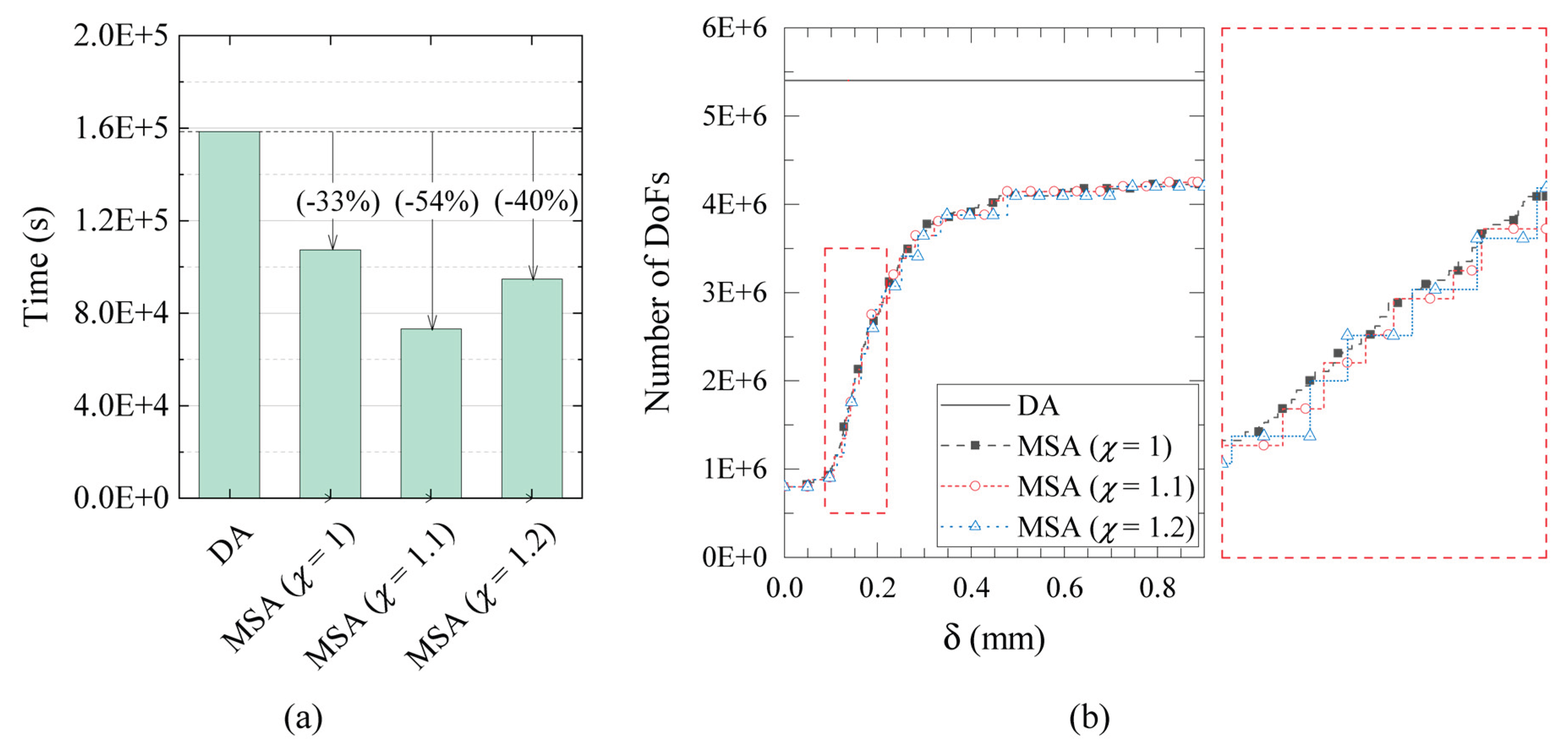
The computational performance of the proposed multiscale model is highlighted in Figure 15, which presents a direct comparison of the computational time and the evolution of the degrees of freedom (DOFs).
As shown in Figure 15-a, MSA analyses achieve a substantial reduction in computational time spent performing numerical simulations compared to the direct analysis. While the DA analysis requires over 16,000 seconds to perform the entire numerical simulation, the proposed MSA requires only a fraction of this time, demonstrating a significant improvement in efficiency. In this context, the use of a larger scale factor (χ) than 1 contributes significantly to reducing computational time. This is particularly evident for the case with χ=1.1, which further reduces computational time by 21% compared to the multiscale analysis with χ=1. Conversely, the use of χ=1.2 reduces the time by only 40%. This data is likely related to the convergence difficulties the model faces when it deactivates the macro-elements and activates the detailed zones. In fact, these are areas where damage should be present, but initially, it is not. For this reason, the solver spends more time to converging.
Figure 15-b clearly demonstrates the reason for the substantial time saving provided by MSA. This figure plots the evolution of the DOFs as a function of the horizontal displacement of the top of the wall (δ). One can observe that the DA analysis curve remains constant, reflecting that the entire domain is discretized with a fine-scale mesh from the beginning. In contrast, MSA analyses start with a very low number of DOFs and only increase progressively as damage necessitates the refinement of macro-elements into micro-regions. This adaptive strategy, which applies the high computational cost of the micro-model only where and when it is needed, is the key to the model's computational efficiency.
The zoomed view of Figure 15-b reveals that the evolution of the degrees of freedom (DOFs) for the multiscale models with χ>1 follows a characteristic sawtooth curve. This behavior highlights the delay in refining the zones that are beginning to be damaged, a deliberate strategy compared to the standard MSA model with χ=1. This controlled delay is precisely what accounts for the reduced time required to complete the simulation, as it prevents the unnecessary activation of fine-scale elements in regions that are not yet critically affected.
In conclusion, a small increase in the scale factor is highly advisable. This is because, as demonstrated by the results, it does not compromise the predictive accuracy of the model, particularly in terms of the load-displacement response and the final failure mechanism. By strategically delaying the refinement process, this approach significantly enhances the computational efficiency of the model, making it a powerful tool for the analysis of large-scale masonry structures.
5. Conclusions
This work introduces a new adaptive concurrent multiscale model for analyzing the failure of masonry structures. This methodology is based on a domain decomposition strategy, which dynamically assigns different levels of resolution, or scales, to the computational domain based on how the material's constitutive behavior evolves. The model is highly effective because it adapts to the specific needs of the simulation. More specifically, the computational domain is divided into coarse- and fine-scale regions. In the coarser regions, the complex microstructure of the masonry is replaced with an equivalent linear elastic homogenized material. The constitutive properties for this material description are systematically derived using a numerical homogenization methodology, which involves identifying a Repeating Cell (RC) for the masonry and performing simulations under periodic boundary conditions.
On the contrary, the fine-scale regions utilize a detailed micro-modeling approach. In these regions, masonry is represented as a two-phase material composed of brick units and mortar joints. This detailed representation is crucial for ensuring the accurate reproduction of complex failure mechanisms. Specifically, the Phase Field Cohesive Zone Model (PF-CZM) was employed to capture and simulate fracture propagation at the microscale level.
A key feature of the proposed strategy is its progressive refinement. During the numerical simulation, the computational domain is refined only when damage mechanisms begin to affect the coarser regions. The refinement is achieved through a specific activation criterion that dictates when and where the finer regions should be activated.
Comparative results with a direct micromechanical analysis demonstrated that the proposed multiscale model was not only highly accurate in replicating the failure mechanisms of masonry structures but was also remarkably computationally efficient. This dual advantage confirmed that the developed methodology provided a powerful and pragmatic tool for the detailed analysis of masonry failure, offering a significant and valuable contribution to the field.
Author Contributions
Conceptualization, Arturo Pascuzzo, Lorenzo Leonetti, Girolamo Sgambitterra; methodology, Girolamo Sgambitterra and Fabrizio Greco; software, Arturo Pascuzzo; validation, Fabrizio Greco and Lorenzo Leonetti; formal analysis, Arturo Pascuzzo and Girolamo Sgambitterra; investigation, Arturo Pascuzzo and Girolamo Sgambitterra; resources, Francesco Fabbrocino; data curation, Arturo Pascuzzo; writing—original draft preparation, Arturo Pascuzzo and Girolamo Sgambitterra; writing—review and editing, Lorenzo Leonetti and Fabrizio Greco; visualization, Girolamo Sgambitterra and Francesco Fabbrocino.
Funding
This research was funded by European Union, "the Next Generation EU – Italian NRRP, Mission 4, Component 2, Investment 1.5, call for the creation and strengthening of 'Innovation Ecosystems', building 'Territorial R&D Leaders' (Directorial Decree n. 2021/3277) - project Tech4You – Technologies for climate change adaptation and quality of life improvement, n. ECS0000009.
Data Availability Statement
No new data were created or analyzed in this study. Data sharing is not applicable to this article.
Conflicts of Interest
The authors declare no conflicts of interest. The funders had no role in the design of the study; in the collection, analyses, or interpretation of data; in the writing of the manuscript, or in the decision to publish the results.
References
- Gaetano, D.; Greco, F.; Leonetti, L.; Pascuzzo, A.; Skrame, A. Comparative finite element modelling approaches for the seismic vulnerability analysis of historical masonry structures: the case study of the Cathedral of Catanzaro (Italy). International Journal of Masonry Research and Innovation 2022, 7, 600–623. [Google Scholar] [CrossRef]
- Greco, F.; Gaetano, D.; Leonetti, L.; Lonetti, P.; Pascuzzo, A.; Skrame, A. Structural and seismic vulnerability assessment of the Santa Maria Assunta Cathedral in Catanzaro (Italy): classical and advanced approaches for the analysis of local and global failure mechanisms. Fracture and Structural Integrity 2022, 16, 464–487. [Google Scholar] [CrossRef]
- Lonetti, P.; Maletta, R. Dynamic impact analysis of masonry buildings subjected to flood actions. Engineering Structures 2018, 167, 445–458. [Google Scholar] [CrossRef]
- Olivieri, C.; Cennamo, C.; Cusano, C.; Cutolo, A.; Fortunato, A.; Mascolo, I. Masonry Spiral Stairs: A Comparison between Analytical and Numerical Approaches. 2022, 12, 4274.
- Iannuzzo, A.; Olivieri, C.; Fortunato, A. Displacement capacity of masonry structures under horizontal actions via prd method. Journal of Mechanics of Materials and Structures 2019, 14, 703–718. [Google Scholar] [CrossRef]
- Fabbrocino, F.; Olivieri, C.; Luciano, R.; Vaiano, G.; Maddaloni, G.; Iannuzzo, A. Seismic performance of historic masonry buildings: A comparative analysis of equivalent frame and block-based methods. Alexandria Engineering Journal 2024, 109, 359–375. [Google Scholar] [CrossRef]
- Greco, F.; Leonetti, L.; Lonetti, P.; Nevone Blasi, P.; Pascuzzo, A.; Porco, G. An interface-based microscopic model for the failure analysis of masonry structures reinforced with timber retrofit solutions. Fracture and Structural Integrity 2024, 18, 210–226. [Google Scholar] [CrossRef]
- Ammendolea, D.; Greco, F.; Leonetti, L.; Lonetti, P.; Pascuzzo, A. An adaptive two-scale model for phase-field fracture simulation in microstructured materials. Composite Structures 2025, 370. [Google Scholar] [CrossRef]
- Ammendolea, D.; Fabbrocino, F.; Leonetti, L.; Lonetti, P.; Pascuzzo, A. Finite element modeling of dynamic crack branching using the moving mesh technique. Engineering Fracture Mechanics 2025, 327. [Google Scholar] [CrossRef]
- Ammendolea, D.; Fabbrocino, F.; Leonetti, L.; Lonetti, P.; Pascuzzo, A. An efficient moving-mesh strategy for predicting crack propagation in unidirectional composites: Application to materials reinforced with aligned CNTs. Composite Structures 2025, 352, 118652. [Google Scholar] [CrossRef]
- Bruno, D.; Greco, F.; Lonetti, P.; Nevone Blasi, P. Influence of micro-cracking and contact on the effective properties of composite materials. Simulation Modelling Practice and Theory 2008, 16, 861–884. [Google Scholar] [CrossRef]
- Bruno, D.; Greco, F.; Lonetti, P. A fracture-ALE formulation to predict dynamic debonding in FRP strengthened concrete beams. Composites Part B: Engineering 2013, 46, 46–60. [Google Scholar] [CrossRef]
- Smilović Zulim, M.; Radnić, J. Anisotropy Effect of Masonry on the Behaviour and Bearing Capacity of Masonry Walls. 2020, 2020, 5676901. [CrossRef]
- Pelà, L.; Cervera, M.; Roca, P. An orthotropic damage model for the analysis of masonry structures. Construction and Building Materials 2013, 41, 957–967. [Google Scholar] [CrossRef]
- Lourenço, P.B. Computations on historic masonry structures. 2002, 4, 301-319. [CrossRef]
- D’Altri, A.M.; Sarhosis, V.; Milani, G.; Rots, J.; Cattari, S.; Lagomarsino, S.; Sacco, E.; Tralli, A.; Castellazzi, G.; de Miranda, S. Chapter 1 - A review of numerical models for masonry structures. In Numerical Modeling of Masonry and Historical Structures, Ghiassi, B., Milani, G., Eds.; Woodhead Publishing: 2019; pp. 3-53.
- Pulatsu, B.; Bretas, E.; Lourenco, P. Discrete element modeling of masonry structures: Validation and application. Earthquakes and Structures 2016, 11, 563–582. [Google Scholar] [CrossRef]
- Pepe, M.; Pingaro, M.; Trovalusci, P.; Reccia, E.; Leonetti, L. Micromodels for the in-plane failure analysis of masonry walls: Limit Analysis, FEM and FEM/DEM approaches. Frat. Integrita Strutr. 2019, 14, 504–516. [Google Scholar] [CrossRef]
- Pulatsu, B.; Erdogmus, E.; Lourenço, P.B.; Lemos, J.V.; Hazzard, J. Discontinuum analysis of the fracture mechanism in masonry prisms and wallettes via discrete element method. Meccanica 2020, 55, 505–523. [Google Scholar] [CrossRef]
- Lourenço, P.J.B.B. Computational strategies for masonry structures. 1997.
- Berto, L.; Saetta, A.; Scotta, R.; Vitaliani, R. An orthotropic damage model for masonry structures. 2002, 55, 127-157. [CrossRef]
- Luciano, R.; Sacco, E. Homogenization technique and damage model for old masonry material. International Journal of Solids and Structures 1997, 34, 3191–3208. [Google Scholar] [CrossRef]
- Trovalusci, P.; Capecchi, D.; Ruta, G. Genesis of the multiscale approach for materials with microstructure. Archive of Applied Mechanics 2009, 79, 981–997. [Google Scholar] [CrossRef]
- Belytschko, T.; Song, J.-H. Coarse-graining of multiscale crack propagation. 2010, 81, 537-563. [CrossRef]
- Bisegna, P.; Luciano, R. Bounds on the overall properties of composites with debonded frictionless interfaces. Mechanics of Materials 1998, 28, 23–32. [Google Scholar] [CrossRef]
- Caporale, A.; Luciano, R.; Sacco, E. Micromechanical analysis of interfacial debonding in unidirectional fiber-reinforced composites. Computers & Structures 2006, 84, 2200–2211. [Google Scholar] [CrossRef]
- Wang, G.; Li, S.; Nguyen, H.-N.; Sitar, N. Effective Elastic Stiffness for Periodic Masonry Structures via Eigenstrain Homogenization. 2007, 19, 269-277. [CrossRef]
- Colatosti, M.; Fantuzzi, N.; Trovalusci, P.; Masiani, R. New insights on homogenization for hexagonal-shaped composites as Cosserat continua. Meccanica 2022, 57, 885–904. [Google Scholar] [CrossRef]
- Masiani, R.; Trovalusci, P. Cosserat and Cauchy materials as continuum models of brick masonry. Meccanica 1996, 31, 421–432. [Google Scholar] [CrossRef]
- Trovalusci, P.; Ostoja-Starzewski, M.; De Bellis, M.L.; Murrali, A. Scale-dependent homogenization of random composites as micropolar continua. European Journal of Mechanics - A/Solids 2015, 49, 396–407. [Google Scholar] [CrossRef]
- Feyel, F.; Chaboche, J.-L. FE2 multiscale approach for modelling the elastoviscoplastic behaviour of long fibre SiC/Ti composite materials. Computer Methods in Applied Mechanics and Engineering 2000, 183, 309–330. [Google Scholar] [CrossRef]
- Nguyen, V.P.; Stroeven, M.; Sluys, L.J. Multiscale failure modeling of concrete: Micromechanical modeling, discontinuous homogenization and parallel computations. Computer Methods in Applied Mechanics and Engineering 2012, 201-204, 139–156. [Google Scholar] [CrossRef]
- Massart, T.J.; Peerlings, R.H.J.; Geers, M.G.D. An enhanced multiscale approach for masonry wall computations with localization of damage. 2007, 69, 1022-1059. [CrossRef]
- Reccia, E.; Leonetti, L.; Trovalusci, P.; Cecchi, A. A multiscale/multi-domain model for the failure analysis of masonry walls: a validation with a combined FEM/DEM approach. International Journal for Multiscale Computational Engineering 2018, 16, 325–343. [Google Scholar] [CrossRef]
- Gulinelli, P.; Aprile, A.; Rizzoni, R.; Grunevald, Y.-H.; Lebon, F. Multiscale Numerical Analysis of TRM-Reinforced Masonry under Diagonal Compression Tests. 2020, 10, 196.
- Addessi, D.; Di Re, P.; Gatta, C.; Sacco, E. Multiscale analysis of out-of-plane masonry elements using different structural models at macro and microscale. Computers & Structures 2021, 247, 106477. [Google Scholar] [CrossRef]
- Greco, F.; Leonetti, L.; Luciano, R.; Nevone Blasi, P. An adaptive multiscale strategy for the damage analysis of masonry modeled as a composite material. Composite Structures 2016, 153, 972–988. [Google Scholar] [CrossRef]
- Driesen, C.; Degée, H.; Vandoren, B. Efficient modeling of masonry failure using a multiscale domain activation approach. Computers & Structures 2021, 251, 106543. [Google Scholar] [CrossRef]
- Chen, W.-X.; Wu, J.-Y. Phase-field cohesive zone modeling of multi-physical fracture in solids and the open-source implementation in Comsol Multiphysics. Theoretical and Applied Fracture Mechanics 2022, 117, 103153. [Google Scholar] [CrossRef]
- Wu, J.-Y. A unified phase-field theory for the mechanics of damage and quasi-brittle failure. Journal of the Mechanics and Physics of Solids 2017, 103, 72–99. [Google Scholar] [CrossRef]
- Wu, J.-Y.; Nguyen, V.P. A length scale insensitive phase-field damage model for brittle fracture. Journal of the Mechanics and Physics of Solids 2018, 119, 20–42. [Google Scholar] [CrossRef]
- Wu, J.-Y.; Nguyen, V.P.; Thanh Nguyen, C.; Sutula, D.; Bordas, S.; Sinaie, S. Phase field modelling of fracture. Advances in Applied Mechanics 2019, 53, 1–183. [Google Scholar]
- Ambati, M.; Gerasimov, T.; De Lorenzis, L. Phase-field modeling of ductile fracture. Computational Mechanics 2015, 55, 1017–1040. [Google Scholar] [CrossRef]
- Vandoren, B.; De Proft, K.; Simone, A.; Sluys, L.J. Mesoscopic modelling of masonry using weak and strong discontinuities. Computer Methods in Applied Mechanics and Engineering 2013, 255, 167–182. [Google Scholar] [CrossRef]
- Farhat, C.; Lesoinne, M.; Letallec, P.; Pierson, K.; Rixen, D. FETI-DP: A dual-primal unified FETI method part I: A faster alternative to the two-level FETI method. International Journal for Numerical Methods in Engineering 2001, 50, 1523–1544. [Google Scholar] [CrossRef]
- COMSOL. COMSOL Multiphysics® v. 5.4; Stockholm, Sweden, 2018.
- Vermeltfoort, A.T.; Raijmakers, T.M.J.; Janssen, H.J.M. Shear tests on masonry walls. 6th North American Masonry Conference 1993, 1183–1193. [Google Scholar]
- Cornelissen, H.A.; Hordijk, D.A.; Reinhardt, H.W. Experimental determination of crack softening characteristics of normalweight and lightweight concrete. 1986.
- Lourenço, P.B.; Rots, J.G. Multisurface interface model for analysis of masonry structures. Journal of Engineering Mechanics 1997, 123, 660–668. [Google Scholar] [CrossRef]
- D'Altri, A.M.; Lo Presti, N.; Grillanda, N.; Castellazzi, G.; de Miranda, S.; Milani, G. A two-step automated procedure based on adaptive limit and pushover analyses for the seismic assessment of masonry structures. Computers and Structures 2021, 252. [Google Scholar] [CrossRef]
Figure 1.
A schematic of a regular brick masonry structure.
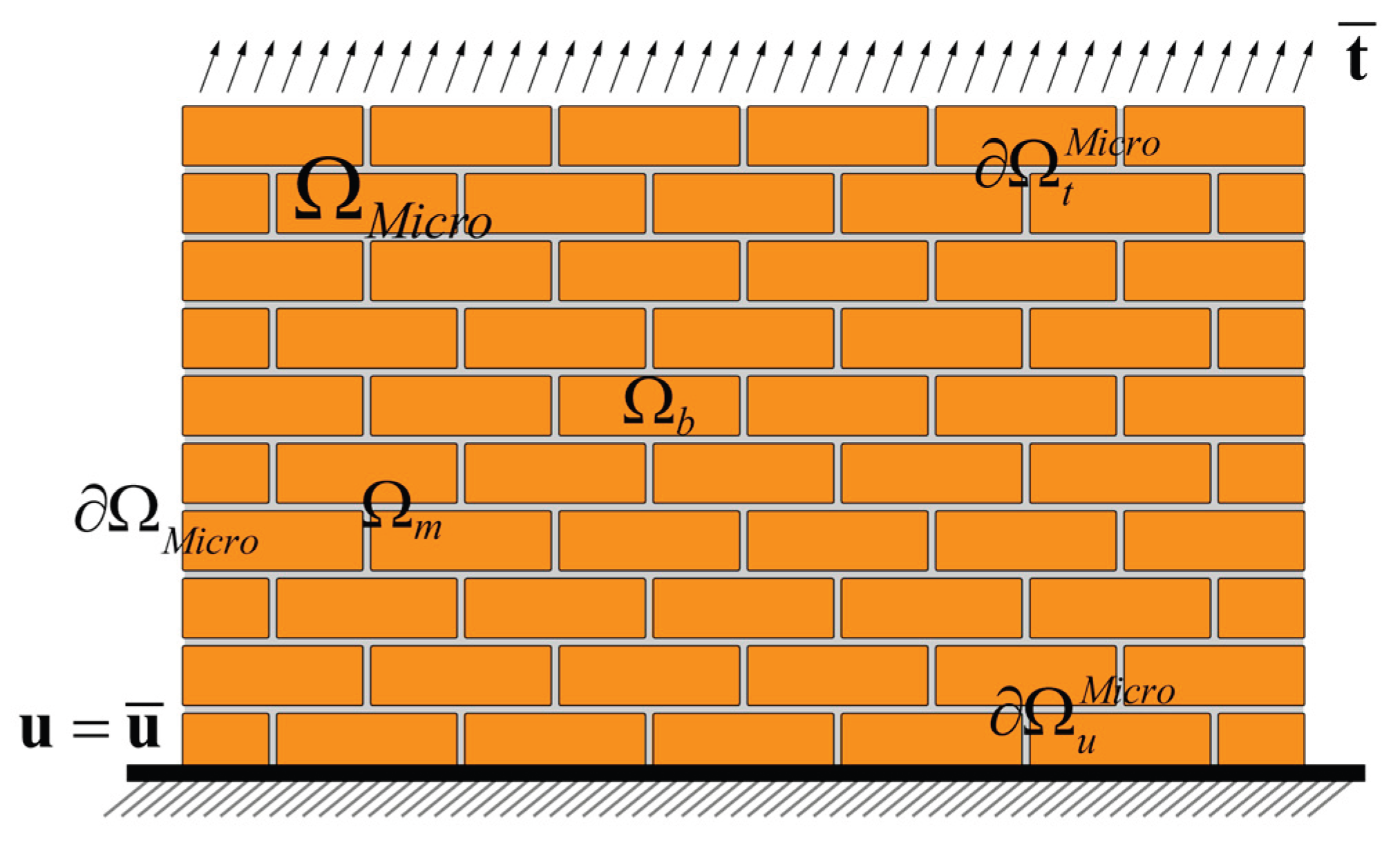
Figure 2.
(a) Identification of a Repeating Cell (RC). (b) Schematization of the masonry by means of homogenized macro-elements.
Figure 2.
(a) Identification of a Repeating Cell (RC). (b) Schematization of the masonry by means of homogenized macro-elements.
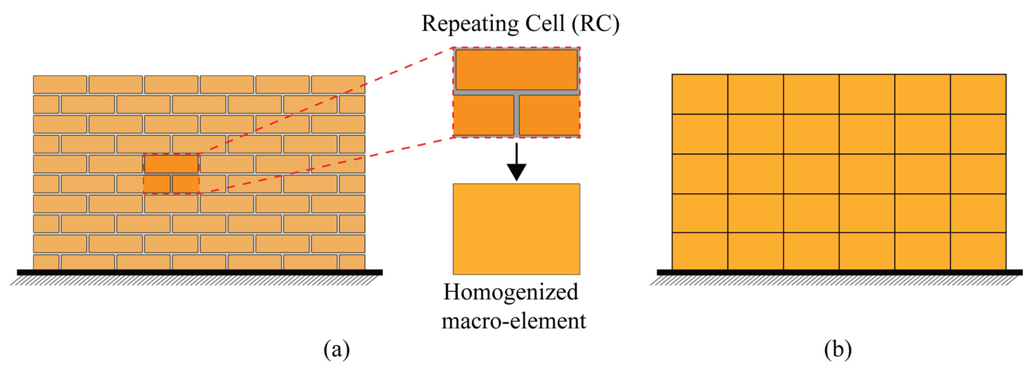
Figure 3.
A schematic of the deformed configuration of the RC of the undamaged masonry due to three pure macrostrain modes under periodic boundary conditions: (a)(b) uniaxial modes (c); shear mode.
Figure 3.
A schematic of the deformed configuration of the RC of the undamaged masonry due to three pure macrostrain modes under periodic boundary conditions: (a)(b) uniaxial modes (c); shear mode.
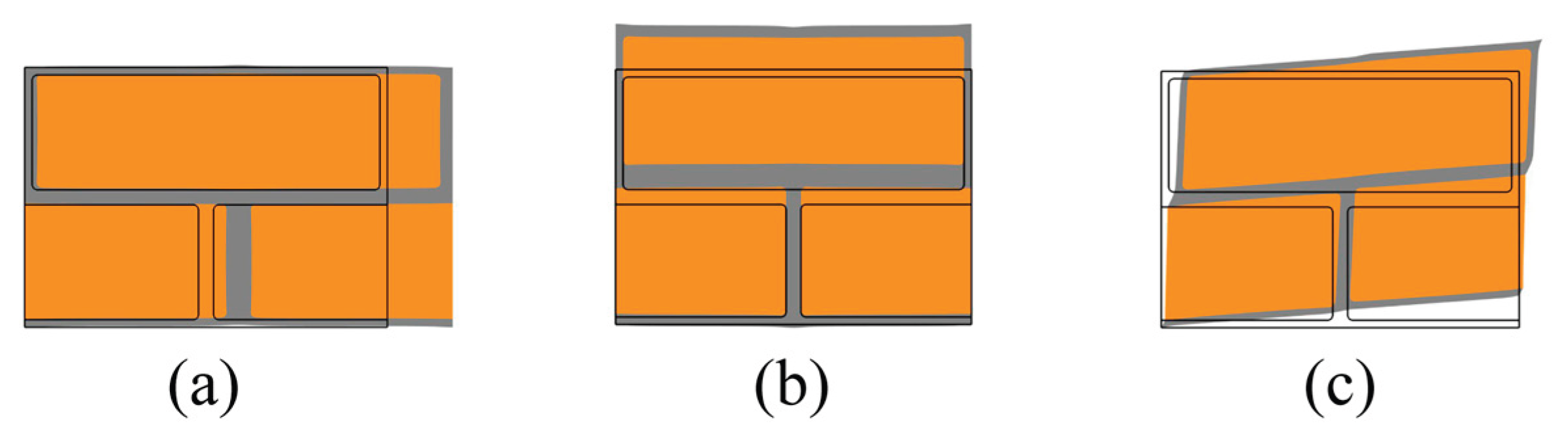
Figure 4.
Figure 4. Micro-macro interface: corner and hanging nodes.
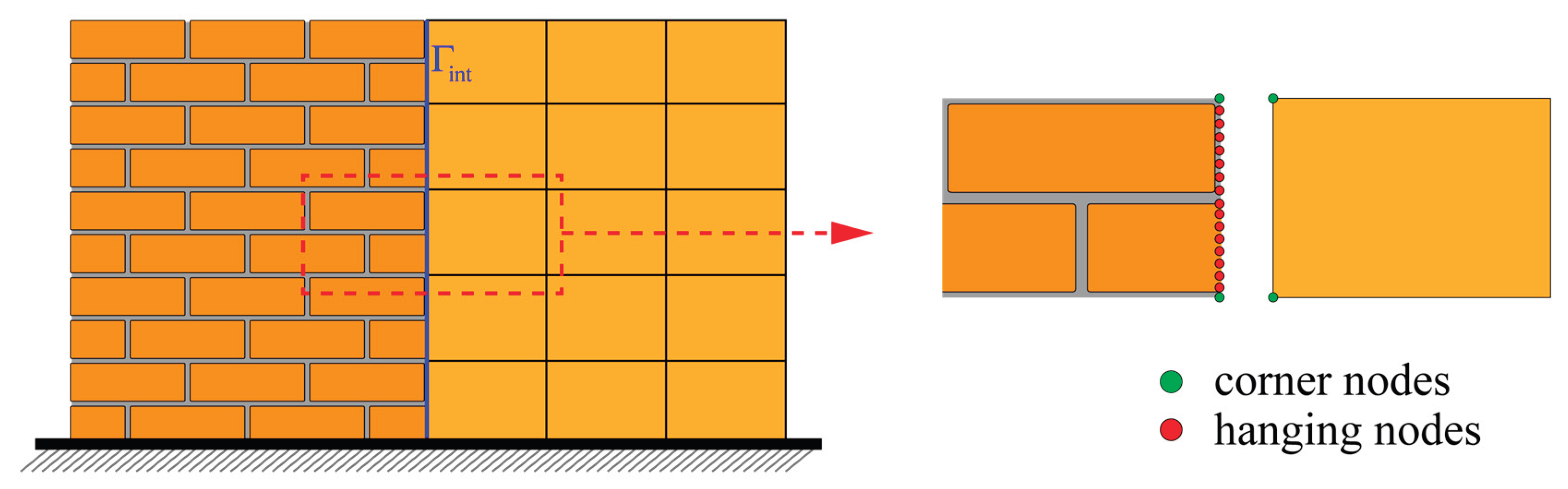
Figure 5.
A schematic of the first failure surface for a periodic masonry scheme. .
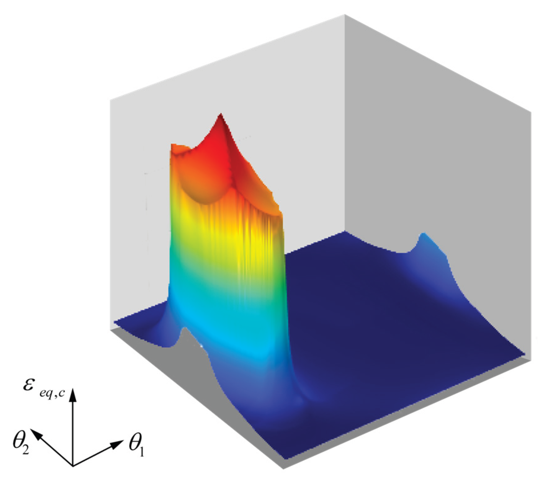
Figure 6.
Flowchart of the proposed concurrent multiscale model algorithm.
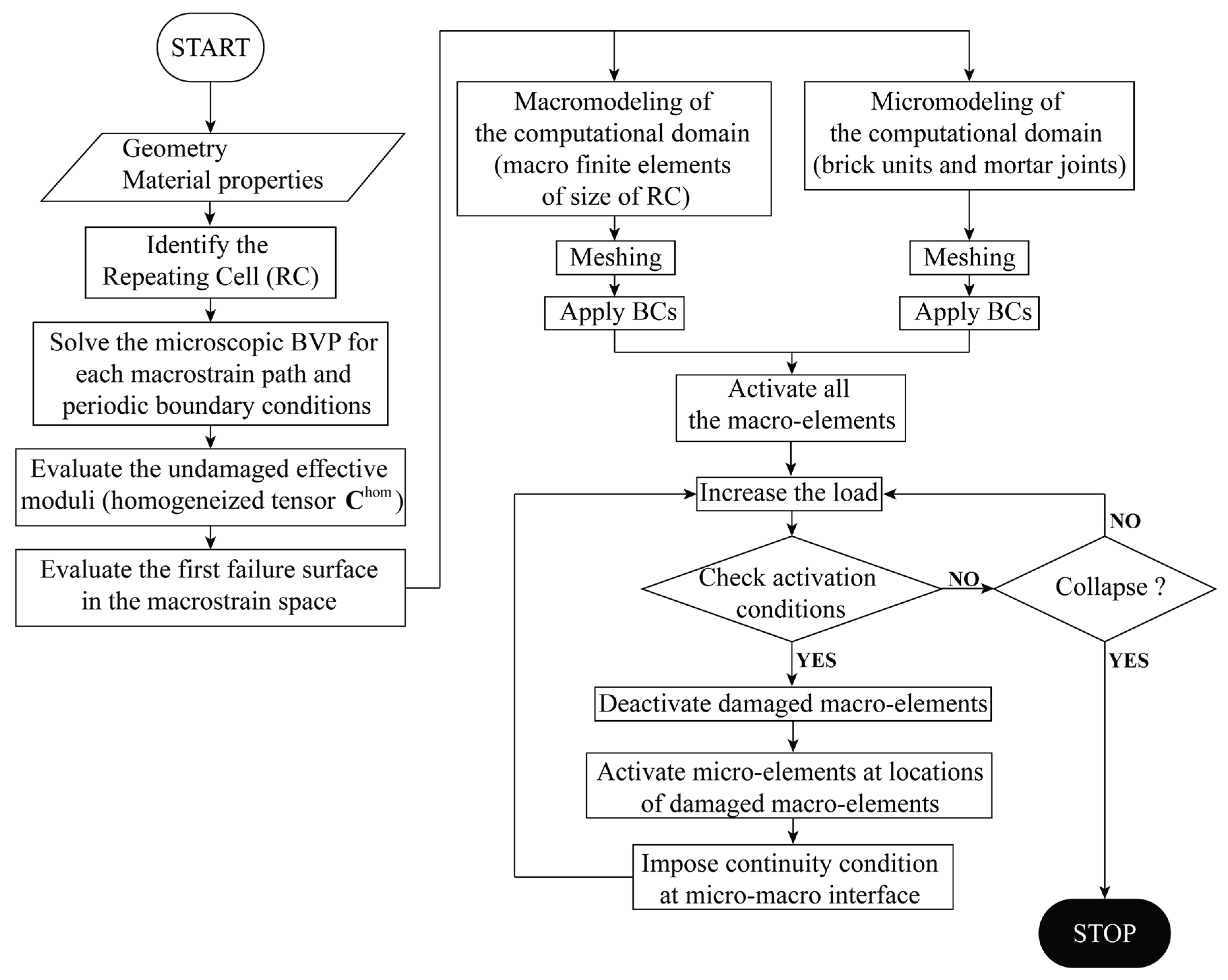
Figure 7.
A schematic of some of the steps followed by the proposed concurrent multiscale model for reproducing the failure of the masonry: (a) Identification of the repeating cell and definition of the equivalent macro element. (b) Beginning of the simulation (masonry entirely sound). (c) Occurrence of failure mechanisms inside the masonry. (d) Total failure of the masonry.
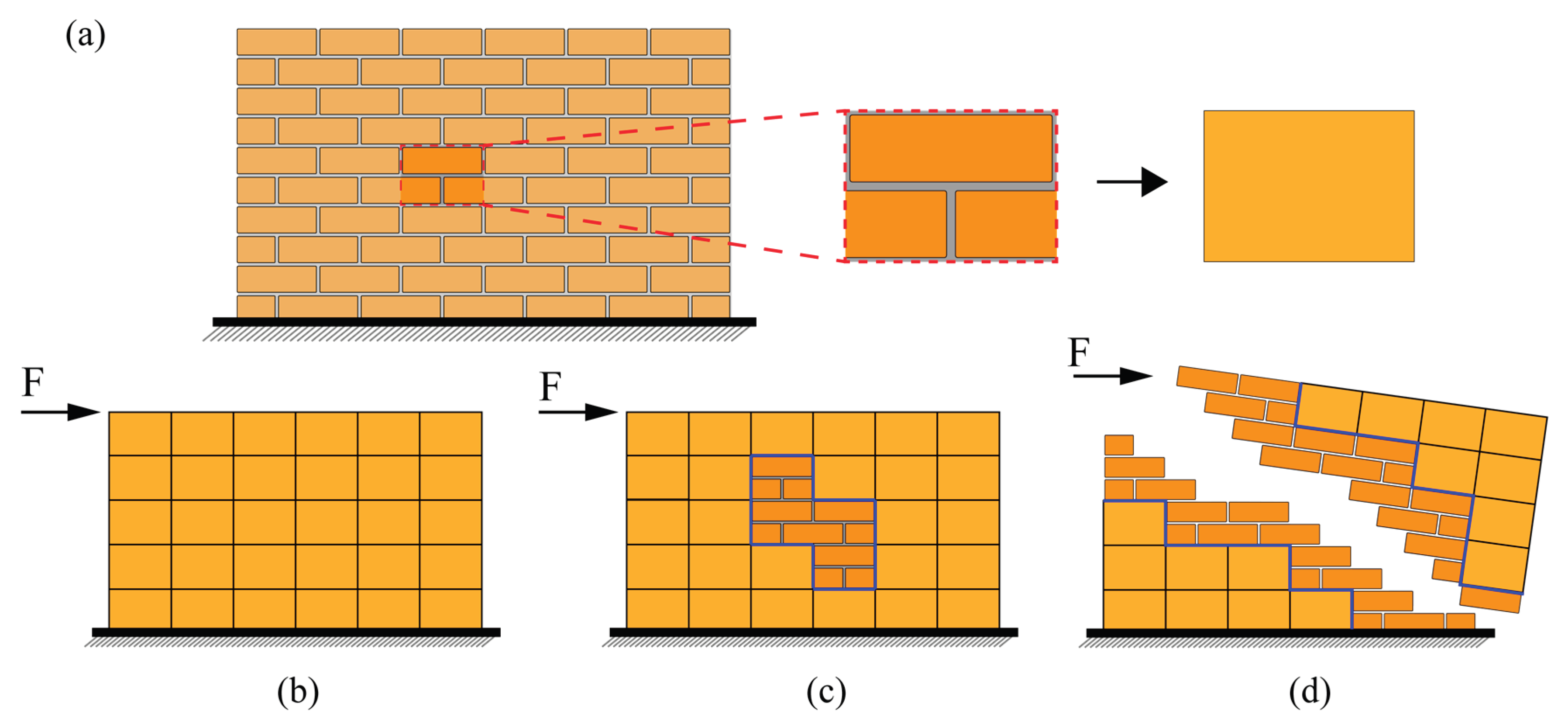
Figure 8.
A masonry wall with an opening. (a) geometry and boundary conditions. (b) a depiction of the computational mesh.
Figure 8.
A masonry wall with an opening. (a) geometry and boundary conditions. (b) a depiction of the computational mesh.
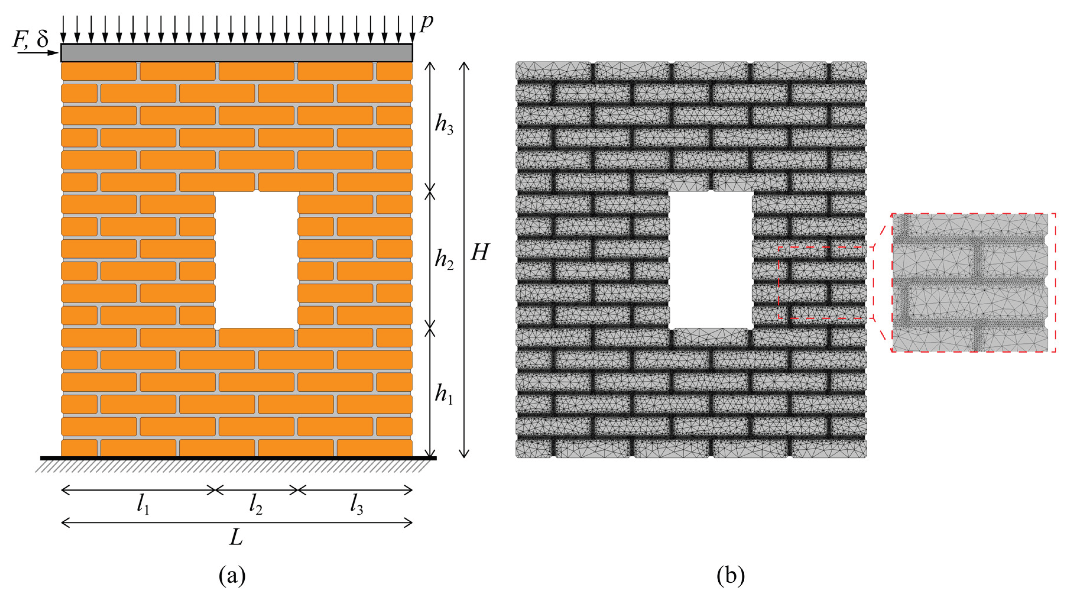
Figure 9.
A masonry wall with an opening: (a) horizontal displacement (d) vs lateral force (F) curve; (b) snapshots of the deformed configurations of the masonry wall relative to the horizontal displacement values.
Figure 9.
A masonry wall with an opening: (a) horizontal displacement (d) vs lateral force (F) curve; (b) snapshots of the deformed configurations of the masonry wall relative to the horizontal displacement values.
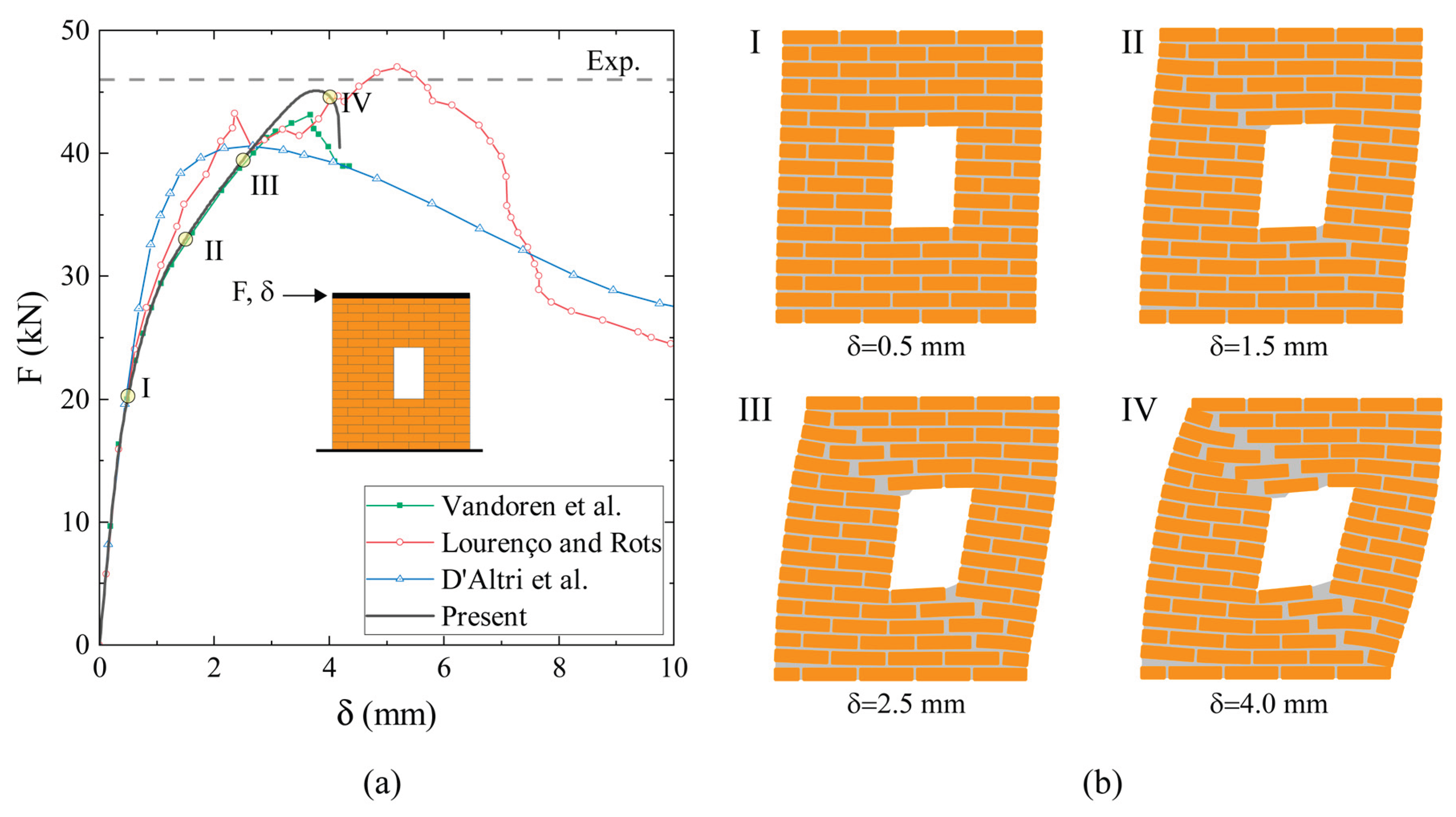
Figure 10.
A masonry wall with an opening: Comparison in terms of damage zones between the proposed method and the results provided by Vermeltfoort et al. [47] (Experimental), Lourenço and Rots [49], Vandoren et al. [44], and D'Altri et al. [50].
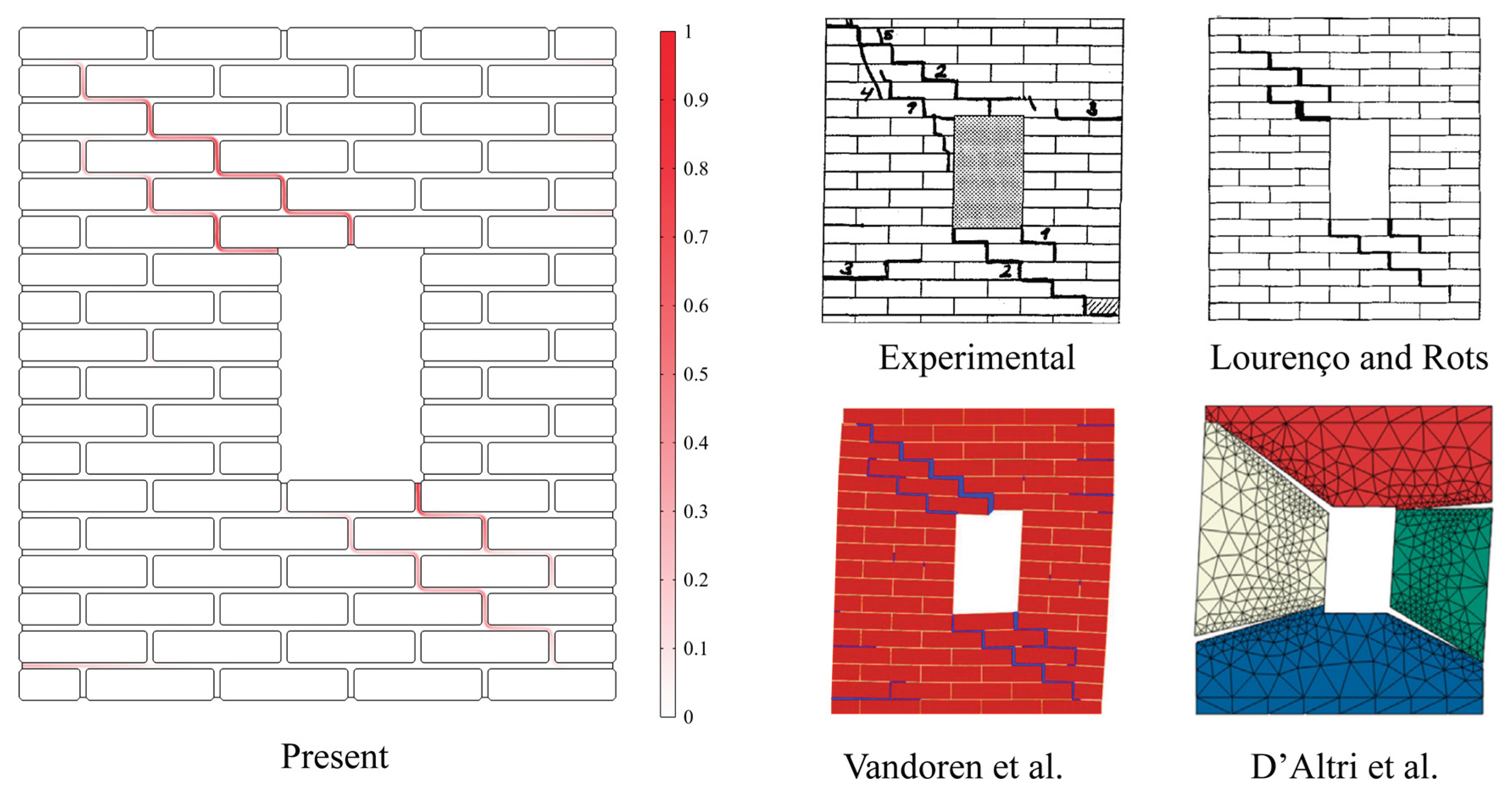
Figure 11.
Failure analysis of a large-scale masonry wall: geometry and boundary conditions.
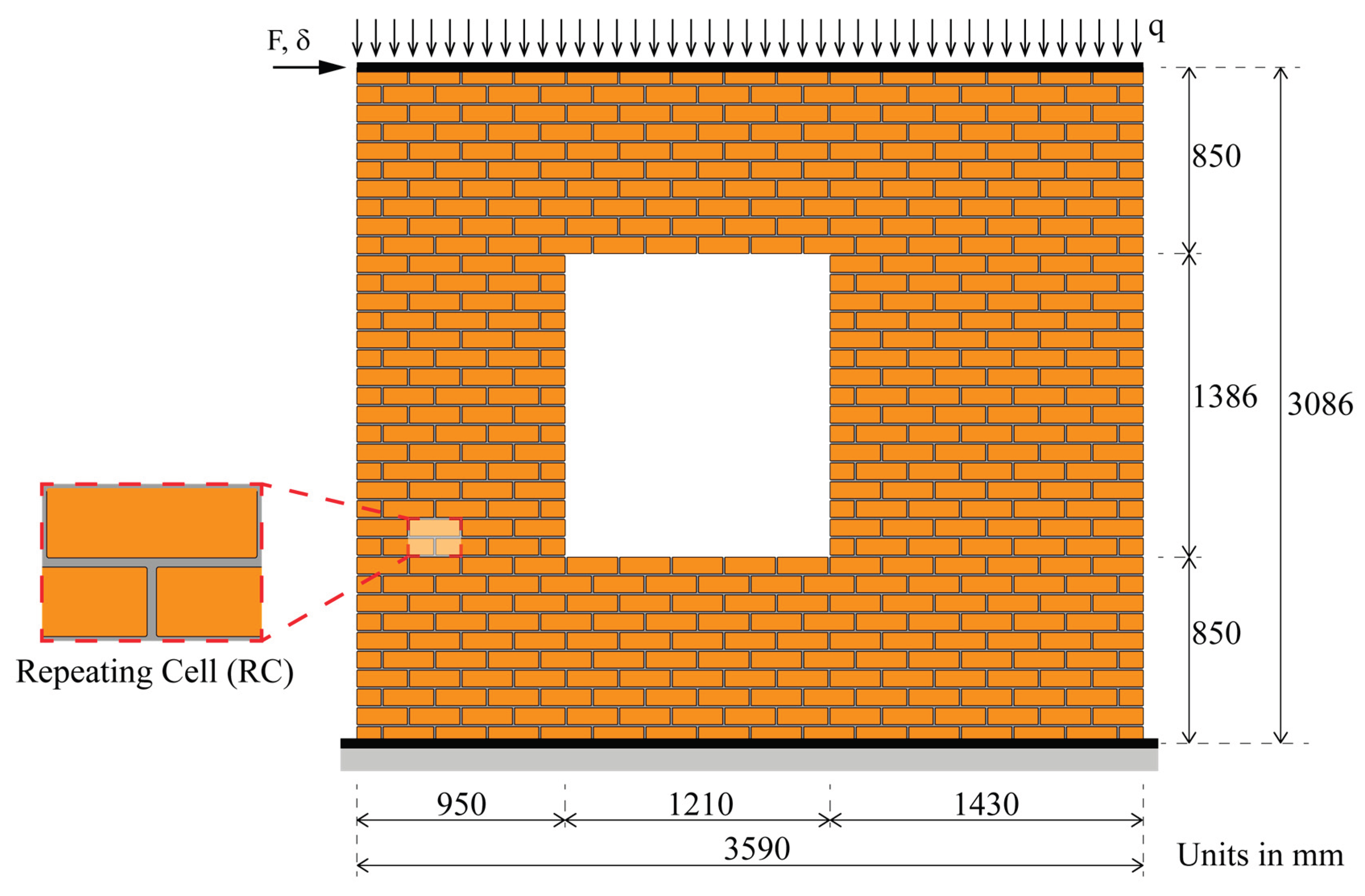
Figure 12.
Failure analysis of a large-scale masonry wall: Computational meshes adopted in numerical simulations. (a) Direct analysis (b) Multiscale analyses.
Figure 12.
Failure analysis of a large-scale masonry wall: Computational meshes adopted in numerical simulations. (a) Direct analysis (b) Multiscale analyses.
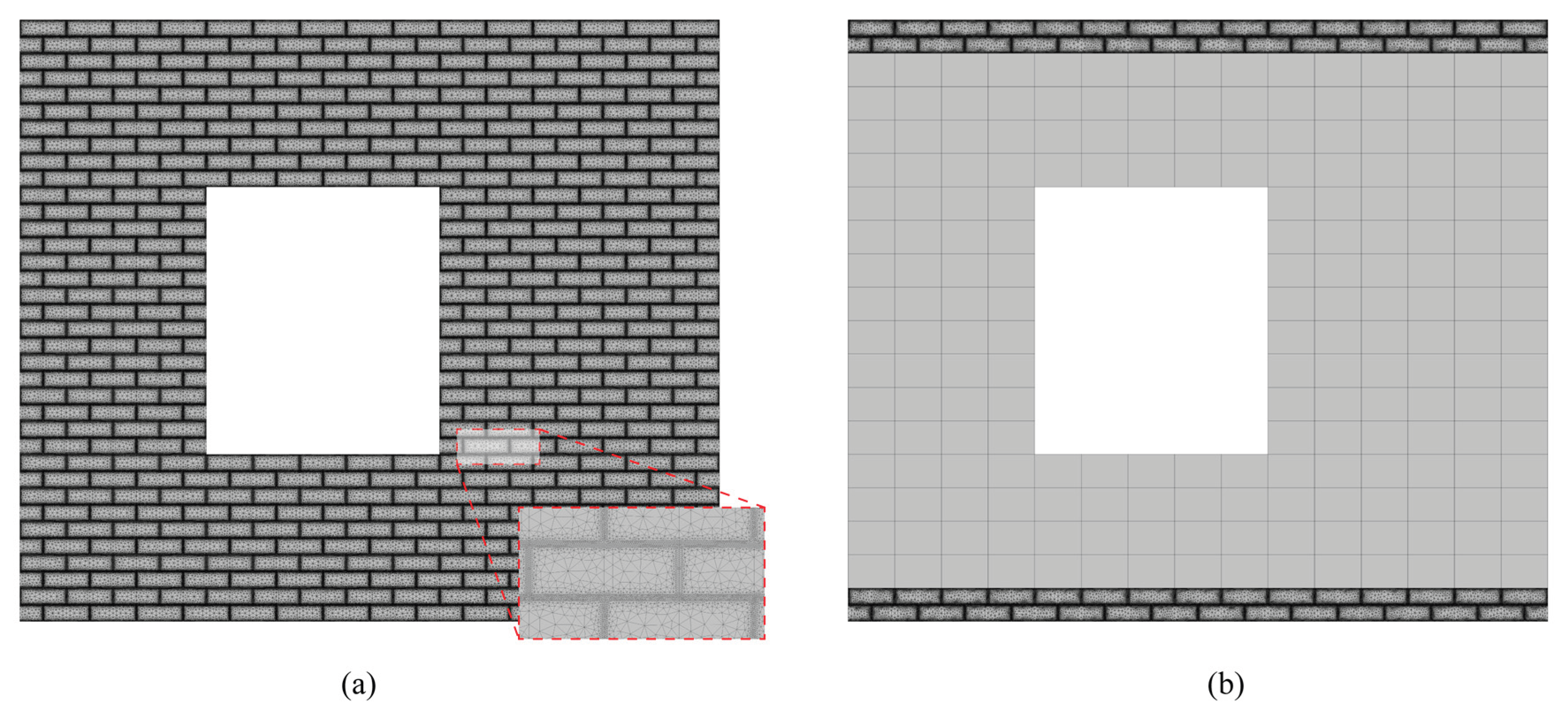
Figure 13.
Failure analysis of a large-scale masonry wall: horizontal displacement (d) vs lateral force (F) curve.
Figure 13.
Failure analysis of a large-scale masonry wall: horizontal displacement (d) vs lateral force (F) curve.
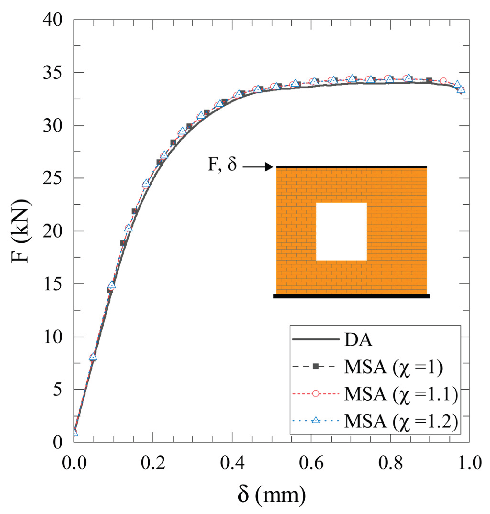
Figure 14.
Failure analysis of a large-scale masonry wall: the phase field distributions (φ) corresponding to the peak force of Figure 13.
Figure 14.
Failure analysis of a large-scale masonry wall: the phase field distributions (φ) corresponding to the peak force of Figure 13.
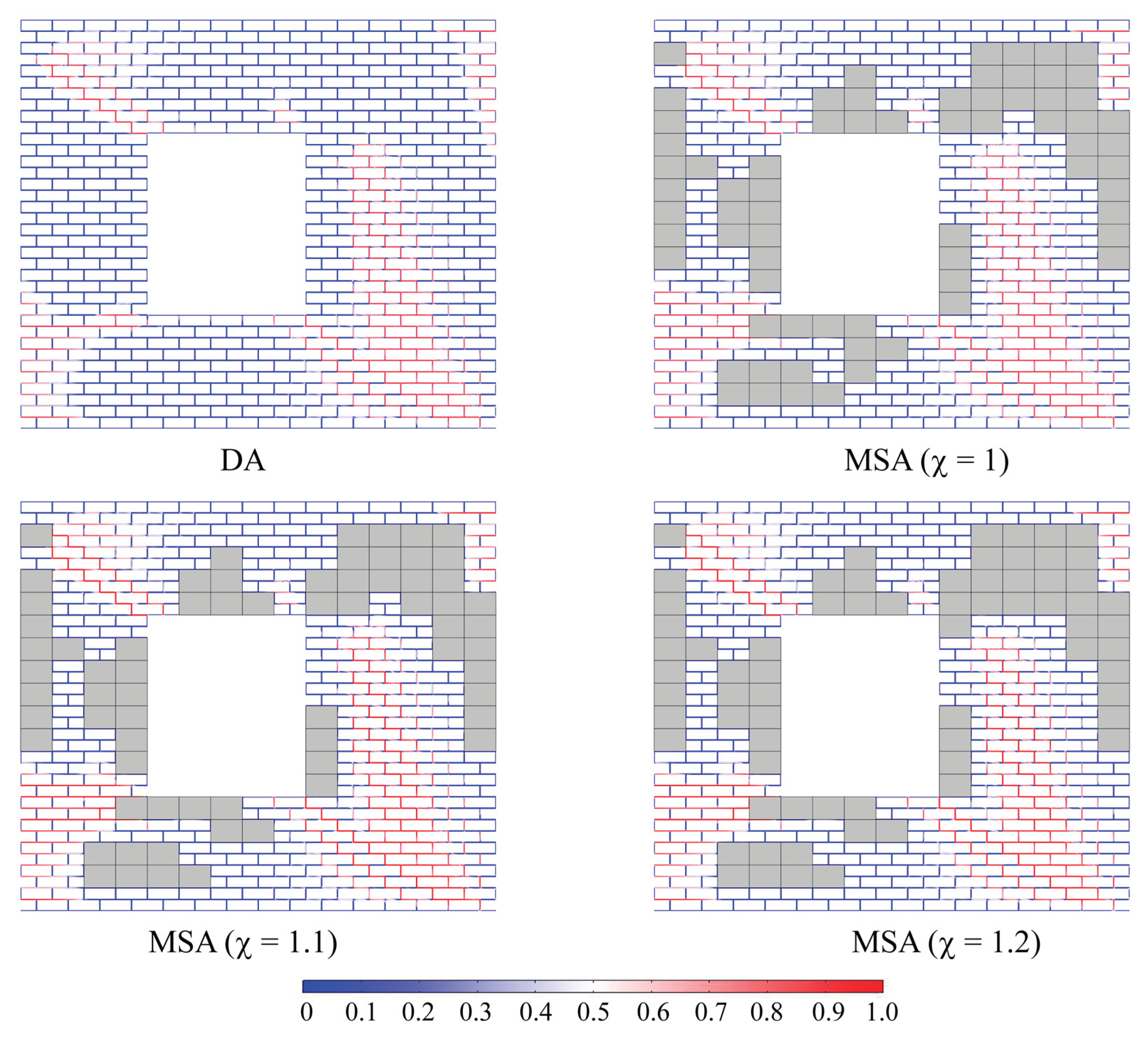
Figure 15.
Failure analysis of a large-scale masonry wall: (a) Computational time comparison; (b) Evolution of Degrees of Freedom (DOFs) with respect to horizontal displacement.
Figure 15.
Failure analysis of a large-scale masonry wall: (a) Computational time comparison; (b) Evolution of Degrees of Freedom (DOFs) with respect to horizontal displacement.
Disclaimer/Publisher’s Note: The statements, opinions and data contained in all publications are solely those of the individual author(s) and contributor(s) and not of MDPI and/or the editor(s). MDPI and/or the editor(s) disclaim responsibility for any injury to people or property resulting from any ideas, methods, instructions or products referred to in the content. |
© 2025 by the authors. Licensee MDPI, Basel, Switzerland. This article is an open access article distributed under the terms and conditions of the Creative Commons Attribution (CC BY) license (http://creativecommons.org/licenses/by/4.0/).
Copyright: This open access article is published under a Creative Commons CC BY 4.0 license, which permit the free download, distribution, and reuse, provided that the author and preprint are cited in any reuse.


