
Submitted:
22 September 2025
Posted:
22 September 2025
You are already at the latest version
Abstract
The symmetry-breaking vibrational response of a gun muzzle, induced by thermo-mechanical coupling effect under continuous firing, is a critical factor degrading shooting accuracy. This study investigates the nonlinear influence of chamber pressure variation on this asymmetric dynamic response. A thermo-mechanically coupled interaction model between a 5.8 mm bullet and its barrel is established using nonlinear finite element methods, incorporating experimentally measured pressure data. The kinematic state of muzzle under a heated barrel condition (after 90 rounds) was systematically analyzed across five chamber pressure levels (90% to 110% of standard). The results reveal a highly nonlinear relationship between chamber pressure and muzzle vibration. Surprisingly, the maximum values for comprehensive radial displacement (10.601×10⁻³ mm), velocity (0.327 m/s), acceleration (11.083 m/s²), swing angle (0.192 mrad), and swing angular velocity (9.166 rad/s) occurred at the 100% standard pressure, not the highest pressure. Reducing the pressure to 90% of the standard effectively suppressed these asymmetric vibrations, with magnitudes declining by 84.28% to 95.49%. This indicates that the symmetry of the muzzle's dynamic state is disrupted under thermal effects, and strategically lowering chamber pressure can restore a more symmetric and stable launch attitude, thereby enhancing accuracy. This study elucidates the nonlinear correlation mechanism between pressure and thermally induced asymmetric vibration, providing a novel perspective for optimizing the accuracy of rapid-fire weapons based on symmetry principles.
Keywords:
asymmetric vibration
; nonlinear dynamics
; thermo-mechanical coupling
; symmetry breaking
; shooting accuracy
; computational simulation
1. Introduction
The pursuit of superior firing accuracy is inherently a problem of controlling initial disturbances and symmetry. For a projectile to strike its target precisely, its muzzle exit velocity and attitude are the decisive factors. Chamber pressure directly influences the projectile’s velocity, while the muzzle’s vibrational characteristics—often exhibiting asymmetric patterns due to gravity—can alter the forces acting on the projectile during the critical exit phase. This leads to variations in the initial conditions of the external trajectory, thereby compromising firing accuracy.
The influence of peak chamber pressure on the amplitude of muzzle initial disturbance is well-known. While this effect might be limited under controlled, ambient temperature conditions, it becomes profoundly exacerbated during rapid firing. The heat accumulation raises the barrel temperature, inducing changes in material properties and generating a pronounced thermo-mechanical coupling effect. This thermal input breaks the thermodynamic and mechanical symmetry of the barrel system, leading to a complex, nonlinear dynamic response where the influence of chamber pressure on muzzle vibration becomes more intense and unpredictable.
Regarding the impact of chamber pressure on projectile motion during launch, the influence of shock waves on the projectile’s state upon exiting the barrel, and the overall performance of the projectile at muzzle exit, domestic and international scholars have conducted research in areas such as in-bore pressure effects, shock wave dynamics, projectile-barrel interaction, and barrel temperature fields.The effects of double-base solid propellant grain size and temperature on burning rate, chamber pressure, and projectile velocity were investigated by Degirmenci[1] and Verberne [2]. A launch system with a filter cartridge was proposed by Chen [3], which increased the initial velocity of the projectile through a segmented combustion chamber design and adjustments to parameters such as auxiliary charge length and barrel length. The variation of breech pressure and the motion characteristics of the projectile when its in-bore movement was obstructed were calculated and analyzed by Guo [4]. The differences in aerodynamic characteristics between projectile flight in a pipe and in free flight under transonic conditions were studied by Hruschka [5], along with the pipe’s influence on projectile drag and flow mechanisms. A recoil reduction method for a 30-mm gun was proposed by Qiu[6]., in which lateral gas ejection was controlled by a piston-spring device. Through numerical simulation based on a one-dimensional two-phase flow model, it was demonstrated that the recoil momentum could be significantly reduced by 31.80% with only a 1.30% loss in muzzle velocity by this symmetric design, without the continuous firing mode being broken. Through live-fire tests, wind tunnel experiments, and computational fluid dynamics simulations, it was found by Doig [7] that shock wave reflection and its interaction with the projectile cause significant changes in drag and normal force.The causes of heat dissipation in a typical small-caliber automatic rifle under hot barrel conditions were analyzed by Dai [8]. The influence of rifling wear on the interior ballistic performance and projectile exit state of 12.7mm ammunition was studied by Shen [9] through a coupled thermal-mechanical finite element analysis model of barrels with rifling damage at different service life stages. A method for testing projectile motion attitude during the semi-constrained period based on active projectile-borne laser was proposed by Zhang [10]. A numerical model of projectile-barrel interaction for sniper rifles was established by Liu [11], and it was found that gravity significantly affects muzzle vibration and projectile yaw in the bore. It was observed by Yang [12] that under hot barrel conditions, the surface temperature of copper-jacketed projectiles approaches the melting point, leading to material shedding and changes in the projectile’s exit attitude. The dynamic response characteristics of the muzzle mass of a 12.7mm heavy machine gun were investigated by Hua [13]. A dynamic bullet engraving resistance model was studied by Xu [14] using a combination of theoretical analysis, experimental research, and numerical simulation.The thermomechanical strength degradation mechanism of 30SiMn2MoVA barrel steel during continuous firing was studied by Chen [15], and it was found that high-temperature softening is a key factor leading to barrel failure. The impact response of barrels with different rifling profiles during bullet engraving was investigated by Wei [16], and it was discovered that polygonal and multi-arc rifled barrels exhibit higher impact resistance compared to rectangular and trapezoidal rifled barrels. The effects of jacket material and thermophysical properties on the in-bore motion of small-caliber projectiles, muzzle motion parameters, and the stress state in the barrel were studied by Huang[17] , Gai[18], Chen [19]. Simulation models were established by HUSSAIN et al. [20,21,22] to address heat transfer issues, and the barrel temperature field under different firing conditions was investigated.
Although these studies have provided valuable insights, they have often overlooked the nonlinear coupling effect of chamber pressure on muzzle vibration during the in-bore motion and its consequent impact on projectile attitude symmetry. Furthermore, the specific influence of chamber pressure variation on the asymmetric vibrational response of a heated barrel remains scarcely explored. The muzzle vibration at the moment of exit is undoubtedly a critical factor that disrupts the symmetry of the projectile’s launch attitude and thus degrades accuracy.
Therefore, studying this coupling mechanism is imperative. Based on the aforementioned considerations, this study employs a 5.8mm rifle to establish a thermo-mechanically coupled bullet-barrel interaction model using the nonlinear finite element method. By integrating actual pressure data, we aim to decipher the nonlinear correlation between chamber pressure and the symmetry-breaking vibrational response of the muzzle under continuous firing conditions. The findings are expected to provide new theoretical insights into accuracy degradation and a novel optimization strategy based on controlling dynamic asymmetry.
2. Chamber Pressure Test Experiment
The chamber pressure during firing was directly measured using the piezoelectric method. The test system is composed of a piezoelectric sensor, a charge amplifier, a data acquisition card, and a computer. The pressure signal is converted into a charge signal by the piezoelectric sensor. The charge signal is then transformed into a voltage signal through the charge amplifier. Finally, the voltage signal is recorded by the data acquisition card. A schematic diagram of the test setup is shown in Figure 1.A 5.8 mm ballistic rifle was used in the experiment.5.8 mm general-purpose ammunition was employed as the test cartridge.
The measured chamber pressure curve is shown in Figure 2. The peak pressure was recorded as 320 MPa. This curve will be converted to obtain the pressure curve acting on boattail. It will serve as the driving force for the projectile’s in-bore motion.
2. Thermo-Mechanical Coupling Modeling Method
To accurately simulate projectile motion and barrel dynamic response, a partitioned coupling numerical method is adopted. A thermo-mechanical coupled dynamic interaction model between the bullet and the barrel is established using the Abaqus simulation platform. The analysis process is shown in Figure 3. It consists of three interrelated computational modules:
1) Transient Heat Transfer Analysis Module
A barrel temperature evolution model is developed based on heat conduction theory. Thermal accumulation during continuous firing is considered. Material thermal properties (thermal conductivity, specific heat capacity) and thermal boundary conditions are defined. The temperature field of the barrel under continuous firing conditions is computed.
2) Static Structural Analysis Module
Considering the combined effects of the temperature and gravity , the static sag data of the barrel is output by defining material parameters, temperature and motion boundary conditions, and applying gravity loads.
3) Explicit Dynamics Module
Results from the previous two modules are integrated as constraints. Friction and contact force models are modified. The motion of the projectile in a heated barrel is simulated and the projectile trajectory and muzzle vibration characteristics are analyzed.
2.1. Geometric Modeling and Meshing
The study objects are a 5.8 mm general-purpose cartridge and a 5.8 mm automatic rifle. Cross-sectional schematic diagrams of their geometric models are shown in Figure 4 and Figure 5.The projectile is designed with a typical three-component structure (copper jacket / lead sheath / steel core).The barrel model retains key features (rifling, forcing cone, etc.).Non-essential structures (threads, barrel bands, etc.) are simplified.
2.2. Basic Assumption
To simplify the computational model, the following reasonable assumptions are made:
1) The material is assumed to be isotropic, and its thermophysical parameters (specific heat capacity, thermal conductivity, elastic modulus, Poisson’s ratio, etc.) are considered to be temperature-dependent;
2) Frictional heating and heat conduction effects are taken into account;
3) Initial deformation caused by the self-weight of the barrel is considered;
4) The influence of air resistance in front of the projectile is neglected.
2.3. Material Constitutive Model
During its in-bore motion, the projectile is subjected to instantaneous high-temperature and high-pressure gas. The jacket undergoes high strain rates, material temperature rise, thermal softening, and strain hardening. These nonlinear mechanical states are experienced. The copper jacket material is specified as H90.The barrel material is designated as 30CrMnSiMoVA.Temperature-dependent material parameters are adopted for the barrel. The Johnson-Cook constitutive model is selected for the jacket material. It is used to describe the thermoviscoplastic behavior. The material parameters are provided in Table 1, Table 2 and Table 3, respectively.
The Johnson-Cook constitutive model can be expressed as:
where: is the equivalent stress, is the equivalent plastic strain, is the equivalent plastic strain rate;A is the yield stress;B is the hardening modulus;C is the strain rate sensitivity coefficient;m is the thermal softening exponent;n is the work hardening exponent; is the reference strain rate;T* is the homologous temperature.
where: Troom is the reference temperature,Tmelt is the melting temperature of the material.
In the table above,E is the elastic modulus, is Poisson’s ratio, is the material density,c is the specific heat capacity, is the thermal conductivity, is the coefficient of thermal expansion.
The Johnson-Cook failure criterion describes the damage degree through the damage parameter D, which can be expressed as:
where: ∆εp is the equivalent plastic strain increment;εf is the material failure strain.
The material failure strain εf can be expressed as:
where: D1~D5 are the damage parameters;σ* is the ratio of pressure to equivalent stress σeff,。
The failure model characterizes material degradation through accumulated damage, describing the reduction in material stiffness. The element damage is defined as:
where: D is the damage parameter,Its value ranges from 0 to 1,Initially, D=0,Material failure occurs when D=1;∆εp is the plastic strain increment within a single time step.
2.4. Boundary Condition
The boundary conditions of the thermo-mechanically coupled bullet/barrel dynamic response model include constraints, thermal boundary condition, and loads.
2.4.1. Constraint
To accurately simulate the actual constraints of the weapon system, the following treatments are applied in the model: the breech end of the barrel is rigidly connected to a ground reference point using multipoint constraints (MPC). Initial sagging deformation due to gravity is retained. These approaches ensure both the rationality of the constraints and accurately captures the initial stress state of the barrel before firing.
2.4.2. Thermal Boundary Condition
During the model construction process, the thermo-mechanical coupling effect under actual firing conditions is fully considered. First, the three-dimensional temperature distribution field of the barrel after 90 rounds of continuous firing is obtained through numerical simulation (as shown in Figure 8). This temperature field is imported as an initial condition into the finite element model.
2.4.3. Loads
The driving force for projectile motion in this thermo-mechanical coupled bullet-barrel interaction model is derived from measured chamber pressure converted using Equation (5).The variation of measured chamber pressure over time is shown in Figure 2.
where, is the propellant mass,M is the projectile mass, is the secondary work coefficient.
2.5. Contact
To address the complex contact issues in the thermo-mechanical coupling of the bullet-barrel system, a finite element model is developed based on the Abaqus general contact algorithm. The model primarily handles three key contact pairs: lead sheath–jacket, steel core–lead sheath, and jacket–barrel inner wall. For contact parameters, the normal behavior is defined using a hard contact criterion to describe pressure-overclosure relationships. The tangential behavior is modeled with a penalty friction formulation. To accurately simulate thermo-mechanical coupling effects, a thermal contact algorithm is incorporated. The frictional heat generation coefficient is set to 0.9 to quantify heat generation from friction. Contact thermal resistance parameters were configured to characterize heat transfer between dissimilar materials. This integrated modeling approach, considering both mechanical and thermal coupling, significantly improves the simulation accuracy of bullet-barrel interaction under high temperature and pressure conditions.
2.6. Grid Independence Verification
The thermo-mechanical coupled bullet/barrel interaction finite element model is discretized using hexahedral elements. Three mesh densities are applied to the barrel for simulation. As shown in Table 4, the computation time increased significantly with higher mesh density. A clear loss of accuracy is observed when coarse mesh is used. Therefore, a mesh scheme with 1.741 million elements for the barrel is adopted. This approach effectively reduced computation time while maintaining numerical accuracy.
3. Model Verification
To validate the thermo-mechanical coupled bullet/barrel interaction finite element model, the in-bore travel distance, muzzle velocity, and surface morphology of the projectile are numerically calculated and compared with experimental results.
Due to the extremely short duration and difficulty in direct observation of the bullet/barrel interaction process, direct validation of the model is challenging. However, muzzle velocity and recovered projectile markings can reflect energy conversion and dynamic behavior during firing. Accurate prediction of these two parameters by the finite element model will indicate high reliability in simulating the actual firing dynamics. Although not comprehensive, this approach remains an effective method for model validation [13,14].
The experimental setup for muzzle velocity measurement and projectile soft recovery is shown in Figure 9. A 5.8 mm automatic rifle and 5.8 mm general-purpose ammunition are used. The muzzle velocity is measured using a system composed of light screens, a timer, and a power supply. Polyurethane foam blocks are employed as the recovery medium. The distance between the light screens is set to 2 m, and the recovery device is placed 10 m from the muzzle. Shooting is performed handheld.
For this projectile muzzle velocity test, a total of 20 rounds of 5.8 mm general-purpose ammunition are fired continuously. The arithmetic mean of the projectile muzzle velocities is calculated, resulting in an average experimental muzzle velocity of 899.8 m/s. Through the thermo-mechanical coupled finite element analysis, the in-bore motion time is determined to be 0.973 ms, the total travel distance is 435 mm, and the computed muzzle velocity is 880.2 m/s. Compared with the experimental average velocity of 899.8 m/s, the error is 2.2%.
The projectiles recovered in the soft recovery test show no surface scratches and no deformation. A comparison between the scratches on the projectile surface at muzzle exit simulated by the thermo-mechanical coupled bullet-barrel interaction finite element model and the actual surface morphology obtained from the test are shown in Figure 10. The comparisons of scratch length and width are presented in Table 5.The errors in scratch dimensions are all less than 5%.
In summary, the comparison between the calculated results (projectile muzzle velocity and surface engraving characteristics) and experimental data demonstrate that the thermal-structural coupled bullet-barrel interaction finite element model is accurate and reliable, and can correctly represent the projectile’s travel and behavior within the barrel.
4. Influence of Chamber Pressure Variation on Muzzle Dynamic Response
Chamber pressure serves as the driving force for the projectile’s in-bore motion and plays a critical role in both the projectile movement and barrel dynamics. During actual firing, variations in propellant charge and ambient temperature can cause significant changes in the pressure curve. Changes in chamber pressure not only alter the projectile’s in-bore motion but also affect the movement of the barrel, particularly at the muzzle, further influencing firing accuracy.
This section investigates the influence of different chamber pressures on the muzzle motion state under the condition of a barrel temperature resulting from continuously firing 90 rounds. The chamber pressure of a barrel when firing a standard projectile with a standard propellant charge and according to standard firing specifications is defined as the standard chamber pressure. Based on the standard pressure, cases with 90%, 95%, 100%, 105%, and 110% of standard pressure are investigated at intervals of 5%.The muzzle motion during projectile travel is analyzed under these pressure conditions. A coordinate system is established to clearly describe the muzzle movement [23].
4.1. Influence of Chamber Pressure Variation on Bullet Velocity
Through analysis using this thermo-mechanical coupled bullet/barrel interaction dynamic response model, the axial displacement and velocity of the projectile’s center of mass during in-bore motion under 100% standard chamber pressure are obtained. The results are shown in Figure 11. The calculated interior ballistic duration is 0.973 ms. The total in-bore travel distance of the projectile is 435 mm. The muzzle velocity is computed as 880.2 m/s. Compared with the experimentally measured average muzzle velocity of 899.8 m/s, the error is 2.2%.
The calculated muzzle velocities of the projectile under five different chamber pressures are shown in Table 6. A significant positive correlation between chamber pressure and muzzle velocity can be observed. The in-bore motion time of the projectile decreases with increasing pressure. This is consistent with the description of the relationship between chamber pressure and projectile initial velocity in literature [3].
4.2. Influence of Chamber Pressure Variation on Muzzle Center Displacement
The temperature field of the barrel is under the condition of continuously firing 90 rounds. The curves of the muzzle center displacement (vertical, horizontal, and radial ) over time under different chamber pressures are shown in Figuer 12, and the displacement values of the muzzle center at the moment when the projectile exits the muzzle are given in Table 7.
As can be seen from Figure 12, the displacement of the muzzle center hardly changes during the first 0.6 ms of the projectile’s engraving , after which it moves upward and to the right. An increase in chamber pressure amplifies the vertical displacement of the muzzle center, as the heightened pressure reduces the effect of gravity on the vertical movement of the muzzle center.
As can be seen from Figure 12 and Table 7, under the condition of a heated barrel with continuous firing of 90 projectiles, the maximum radial displacement at the center of the muzzle at the moment of projectile exit occurs at 100% standard chamber pressure (10.601μm). And the horizontal displacement dominates in the radial composite displacement. In contrast, the minimum radial displacement at the center of the muzzle at the moment of projectile exit is observed at 90% standard chamber pressure (0.829μm).
4.3. Influence of Chamber Pressure Variation on Muzzle Center Velocity and Acceleration
Figure 13 shows the time-varying curves of the muzzle center velocity and acceleration (vertical, horizontal, and radial) under different chamber pressures after continuously firing 90 rounds. The muzzle center velocity and acceleration values at the moment of projectile exit are listed in Table 8.
As can be seen from Figure 13 and Table 8, under the heated barrel condition after 90 consecutive rounds, the maximum comprehensive radial velocity of the muzzle center at projectile exit (0.327 m/s) occurred at 100% standard chamber pressure. The minimum comprehensive radial velocity and acceleration (0.04 m/s and 1.742 m/s²) were observed at 90% standard chamber pressure. It can be concluded from Table 8 that as the chamber pressure increases, the horizontal acceleration of the muzzle center at projectile exit increases,so as the comprehensive radial acceleration.
4.4. Influence of Chamber Pressure Variation on Muzzle Plane Swing Angle and Angular Velocity
The temperature field of the barrel is under the condition of continuously firing 90 rounds. The time-varying curves of the muzzle plane swing angle and angular velocity (vertical, lateral, and comprehensive) under different chamber pressures are shown in Figure 14. The values of the muzzle plane swing angle and angular velocity at the moment of projectile exit are listed in Table 9.
As shown in Figure 14 and Table 9, under the heated barrel condition after continuously firing 90 projectiles: the maximum muzzle plane swing angle and angular velocity at projectile exit (0.192 mrad and 9.166 rad/s) are observed at 100% standard chamber pressure; the minimum values (0.022 mrad and 0.413 rad/s) are recorded at 90% standard chamber pressure.
5. Conclusions
This study reveals the nonlinear and asymmetric nature of the muzzle’s dynamic response under the thermo-mechanical coupling conditions of continuous firing. The key finding is that the symmetry of the muzzle’s motion is severely disrupted under thermal accumulation, and contrary to simple linear intuition, the standard (100%) chamber pressure does not yield the most stable state but instead excites the most significant asymmetric vibrations.
The quantitative results demonstrate that reducing the chamber pressure to 90% of the standard value can effectively suppress the nonlinear vibration and restore a more symmetric dynamic state at the muzzle. This is evidenced by the dramatic reductions across all kinematic parameters: comprehensive radial displacement (92.18%), comprehensive radial velocity (87.76%), comprehensive radial acceleration (84.28%), muzzle plane swing angle (88.54%), and muzzle plane swing angular velocity (95.49%), as shown in Table 10.
This phenomenon is attributed to the thermal softening of the barrel material and the degradation of bullet jacket materials under heat, which amplify the asymmetric impact of pressure pulses. The findings align with muzzle dynamics theory, confirming that reducing muzzle disturbance is key to improving shooting accuracy.
In conclusion, this research demonstrates that strategic control of chamber pressure serves as an effective method for managing the symmetry-breaking vibrations in thermally compromised barrels. It quantifies a critical nonlinear relationship in launch dynamics and provides a new optimization paradigm for the design of high-rate-of-fire weapons aiming for superior accuracy.
Author Contributions
Conceptualization, Z.L.W.; methodology, L.C.; software, L.C. and Z.Y.X.; validation, L.C. and J.S.; formal analysis, L.C.; investigation, L.C.; resources, Z.L.W. and J.S.; data curation, L.C.; writing—original draft preparation, L.C.; writing—review and editing, L.C.; funding acquisition, J.S. All authors have read and agreed to the published version of the manuscript.”
Funding
This research was funded by the National Natural Science Foundation of China, grant number 52475108.
Institutional Review Board Statement
Not applicable.
Informed Consent Statement
Not applicable.
Data Availability Statement
The original contributions presented in this study are included in the article. Further inquiries can be directed to the corresponding author.
Acknowledgments
The authors thank the reviewers for their constructive comments, which helped improve the quality of this manuscript.
Conflicts of Interest
The authors declare no conflicts of interest. The funders had no role in the design of the study; in the collection, analyses, or interpretation of data; in the writing of the manuscript; or in the decision to publish the results.
References
- Degirmenci E. Effects of grain size and temperature of double base solid propellants on internal ballistics performance[J]. FUEL, 2015, 146:95-102. arXiv:10.1016/j.fuel.2015.01.027.
- Dynamics of precision-guided projectile launch: fluid–structure interaction[J]. Acta Mechanica, 2021, 232:1147-1161.
- Chen Z J, He Z, Ma H H, et al. Experimental research on the launching system of auxiliary charge with filter cartridge structure[J]. Defence Technology, 2024, 31:41-48.
- Guo Z. Analysis of the projectile motion was blocked in gun bore[C]//IOP Conference Series: Earth and Environmental Science. IOP Publishing, 2021, 647(1): 012003.
- Hruschka R, Klatt D. In-pipe aerodynamic characteristics of a projectile in comparison with free flight for transonic Mach numbers[J]. Shock Waves, 2019, 29: 297-306. [CrossRef]
- Qiu, M., Si, P., Song, J., & Liao, Z. (2021). Recoil Reduction Method of Gun with Side to Rear Jet Controlled by Piston Motion. Symmetry, 13(3), 396. [CrossRef]
- Doig G, Wang S, Kleine H, et al. Aerodynamic analysis of projectiles in ground effect at near-sonic mach numbers[J]. AIAA Journal, 2016, 54(1):150-160. [CrossRef]
- DAI C, CAO Y.F, HE Long, et al. Cause analysis and result prediction of thermal dispersion for typical small caliber rifles[J]. Acta Armamentarii, 2024, 45(03):885-892.
- SHEN C, ZHOU K.D, LU Ye, et al. Research on the influence of damaged barrel on interior ballistic performances and muzzle-leaving state of bullet[J]. Acta Armamentarii, 2019, 40(04):718-727.
- Zhang F, Zhang R, Xu Q, et al. The Test method of the Projectile’s Motion Attitude in the Semi-constraint Period[C] //2020 7th International Forum on Electrical Engineering and Automation (IFEEA). IEEE, 2020: 612-615.
- LIU G.Q, XU C, DING C.J. Numerical calculation on the interaction between bullet and sniper rifle[J]. Journal of Vibration and Shock, 2017, 36(19):1-7.
- YANG Y.Z, ZHANG X.Y, XU C. The interaction between copper jacket projectile and barrel under different temperature based on thermo-mechanical coupling finite element model[J]. Journal of Vibration and Shock, 2020, 39(10):44-51.
- HUA H.L, LIAO Z.Q, ZHANG X.Y. Muzzle dynamic characteristics analysis and its matching for firing accuracy improvement[J]. Journal of Vibration and Shock, 2017, 36(8):29-33.
- XU H, HUANG C.L, WANG X.K, et al. Theoretical and experimental study of projectile dynamic engraving resistance[J]. Acta Armamentarii, 2022, 43(09):2263-2273.
- Chen J, Wang W, Jin P, et al. Thermo-mechanical analysis of strength degradation of 30SiMn2MoVA gun barrel material during continuous shooting[J]. Engineering Failure Analysis, 2022, 139: 106438. [CrossRef]
- Wei Z, Cheng Y, Wang Z, et al. Simulation study on the impact response of barrels with different rifling profiles during bullet engraving[J]. Modelling and Simulation in Engineering, 2022(1): 6407452. [CrossRef]
- HUANG C.L, JIANG M.F, CHEN L, et al. Influence of the material of small-caliber bullet jacket on its motion in hot barrel[J]. Acta Armamentarii, 2022, 43(09):2241-2251.
- GAI Z.Y, ZHOU K.D, LU Y, et al. Stress states of anisotropic material gun barrel by firing the projectiles with different jacket materials[J]. Acta Armamentarii, 2024, 45(11):4119-4132.
- CHEN L, XIE K, LU D.B, et al. Influence of thermal physical properties on muzzle motion parameters under heated barrel condition[J]. Transactions of Beijing Institute of Technology, 2025, 45(02):185-194.
- HUSSAIN N, QAYYUM F, PASHA R A, et al. Develop-ment of multi-physics numerical simulation model to inves-tigate thermo-mechanical fatigue crack propagation in an autofrettaged gun barrel [J]. Defence Technology, 2021, 17(5): 1579-1591.
- Zieliński M, Koniorczyk P, Surma Z, et al. Numerical study of heat transfer in a gun barrel made of selected steels[J]. Energies, 2022, 15(5): 1868. [CrossRef]
- SUSANTEZ C, CALDEIRA A B. Heat transfer modelling and simulation of a 120 mm smoothbore gun barrel during interior ballistics[J]. Defence Science Journal, 2022, 72(1):30-39. [CrossRef]
- RUI X.T. Launch dynamics of multibody system[M]. 1st ed. Beijing: National Defense Industry Press, 1995.
Figure 1.
Pressure test diagram of 5.8mm ballistic gun.
Figure 2.
Bore pressure test result diagram.
Figure 3.
Thermo-mechanical coupling analysis flowchart.

Figure 4.
The 5.8 mm bullet geometric model.
Figure 5.
Semi-profile sketch of the geometric model of a 5.8 mm automatic rifle barrel.
Figure 6.
Semi-section grid diagram of bullet.
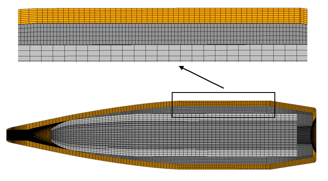
Figure 7.
Semi-section grid diagram of the barrel.
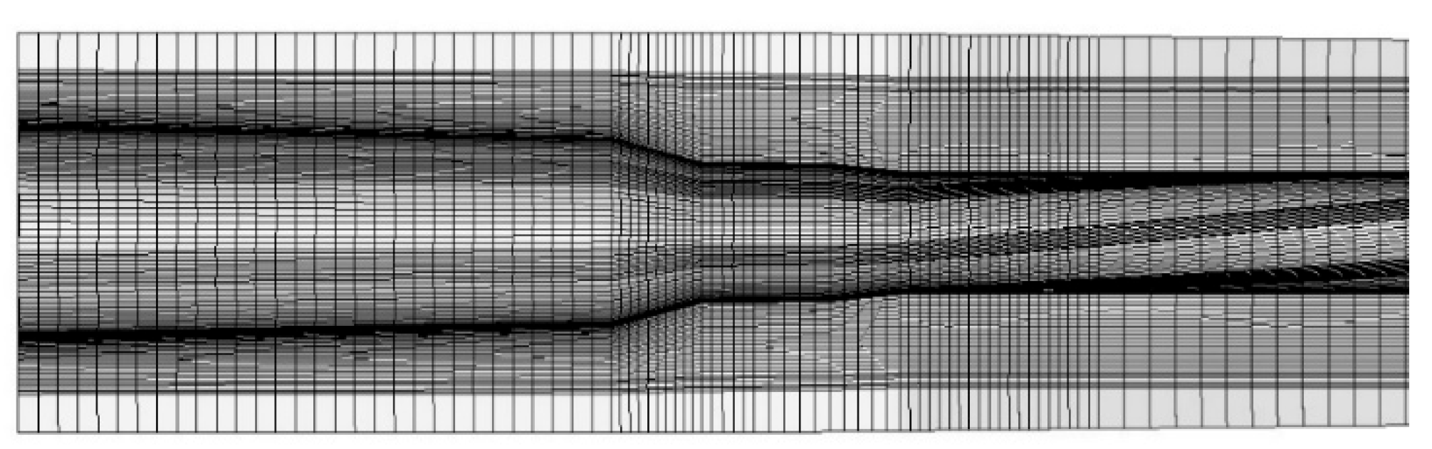
Figure 8.
Barrel temperature field under 90 rounds of continuous shooting.
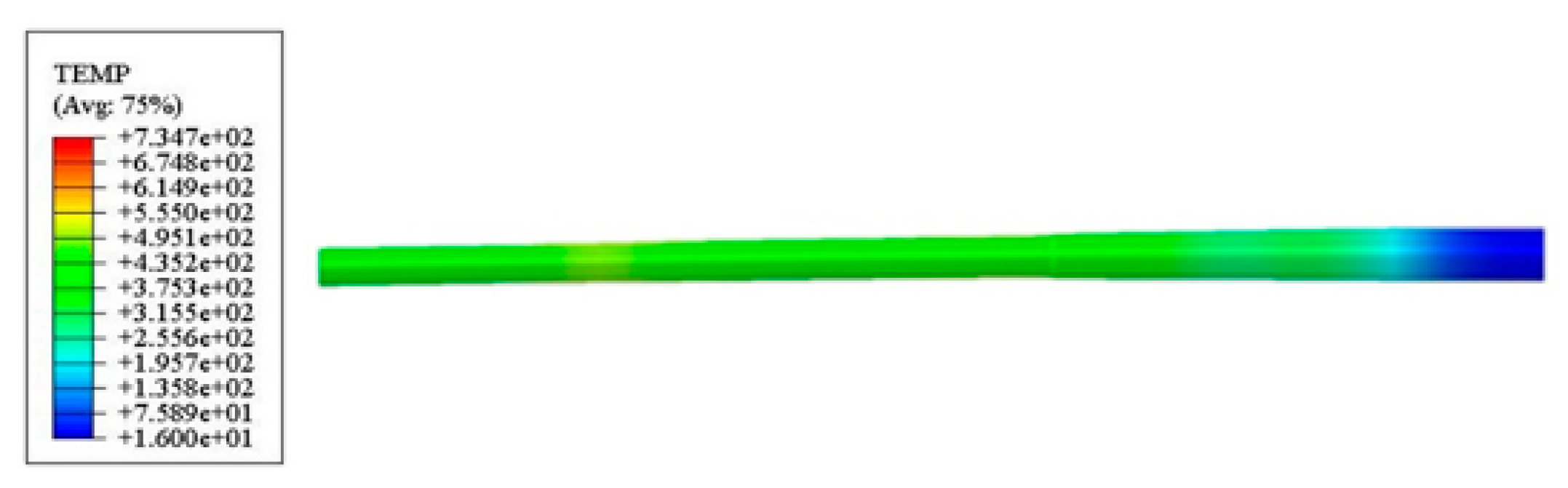
Figure 9.
Schematic diagram of test device and test site.
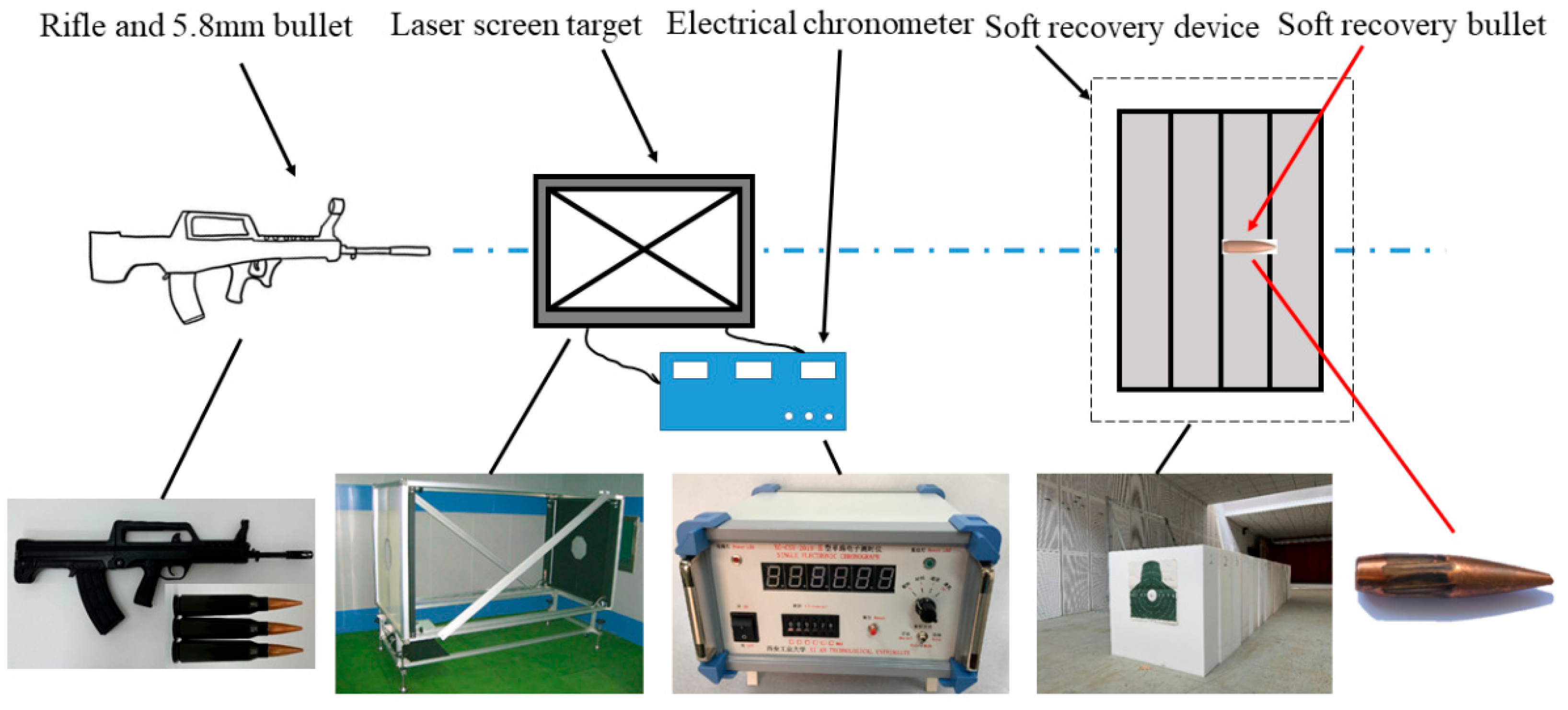
Figure 10.
Comparsion of soft recovery projectile and simulation.
Figure 11.
The change of axial displacement and velocity of projectile with time.
Figure 12.
Influence of different chamber pressure on the center displacement of muzzle.
Figure 13.
Influence of different chamber pressure on the velocity and acceleration of muzzle center.
Figure 13.
Influence of different chamber pressure on the velocity and acceleration of muzzle center.
Figure 14.
Influence of different chamber pressure on the swing angle and angular velocity of the muzzle plane.
Figure 14.
Influence of different chamber pressure on the swing angle and angular velocity of the muzzle plane.
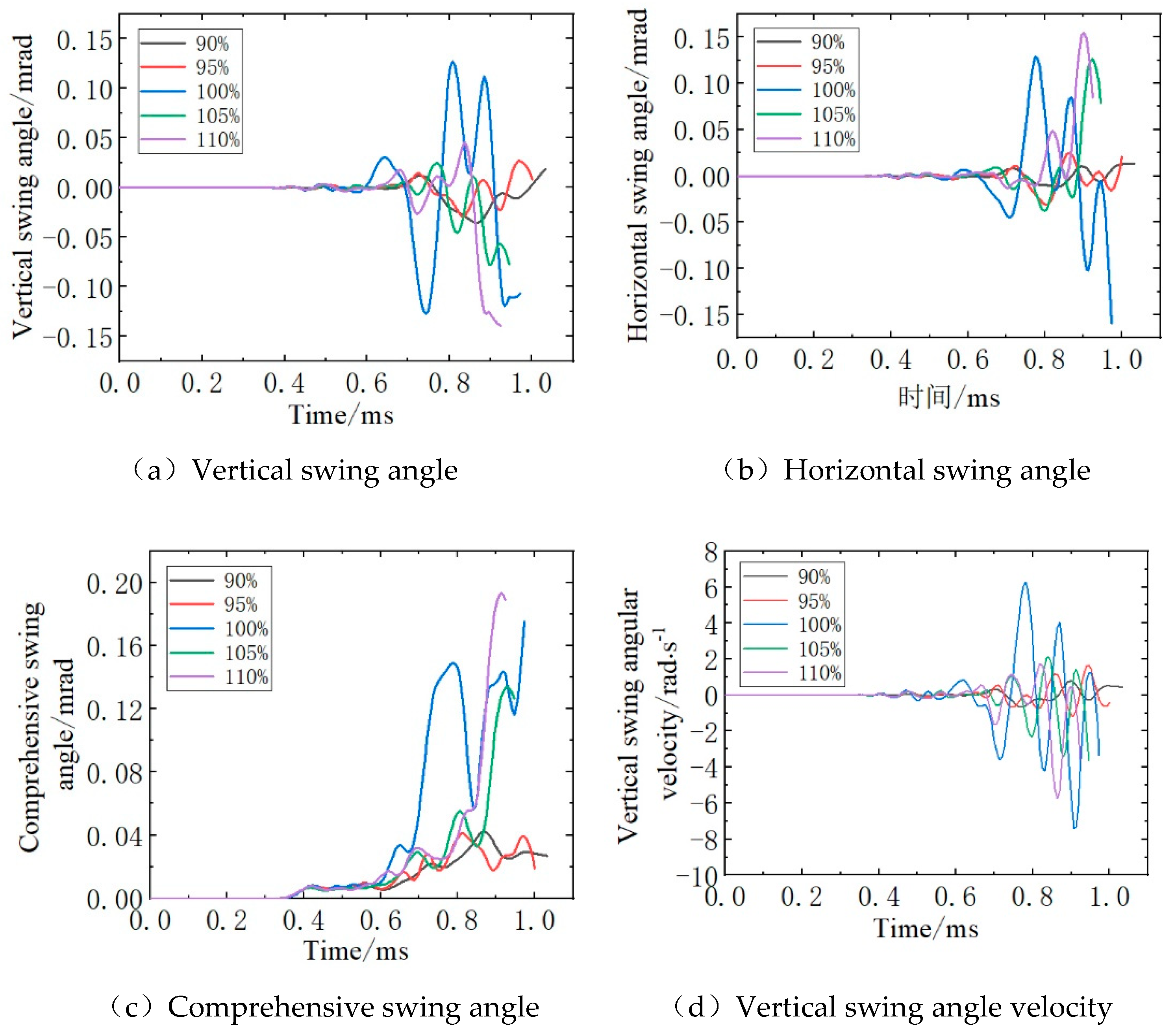
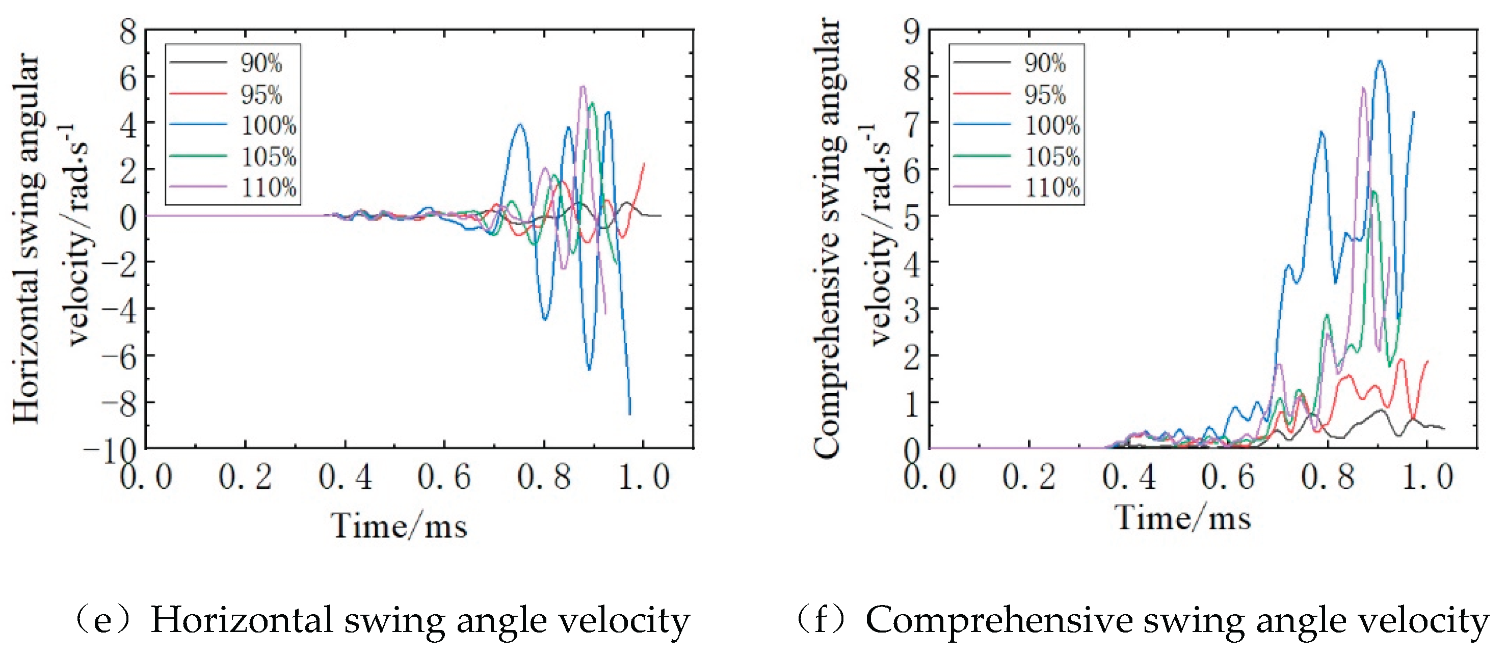

Table 1.
Mechanical and thermodynamic parameters of H90.
| Parameter type | Value | ||||||
|---|---|---|---|---|---|---|---|
| Elastic and thermal | E/GPa | ρ/(kg·m-3) | c/(J·kg-1·K-1) | λ/(W·m-1·K-1) | |||
| 112 | 0.31 | 8730 | 375 | 110 | |||
| Plastic | A/MPa | B/MPa | C | n | m | Tm/K | |
| 112 | 505 | 0.09 | 0.42 | 1.68 | 1082 | 1 | |
| Damage failure | D1 | D2 | D3 | D4 | D5 | ||
| 0.54 | 4.89 | -3.03 | 0.014 | 1.12 | |||
Table 2.
Mechanical and thermodynamic parameters of lead sheath.
| Parameter type | Value | ||||||
|---|---|---|---|---|---|---|---|
| Elastic and thermal | E/GPa | ρ/(kg·m-3) | c/(J·kg-1·K-1) | λ/(W·m-1·K-1) | |||
| 17 | 0.42 | 11340 | 130 | 207 | |||
| Plastic | A/MPa | B/MPa | C | n | m | Tm/K | |
| 8 | 110 | 0.09 | 0.52 | 1.1 | 760 | 1 | |
Table 3.
Mechanical and thermodynamic parameters of 30CrMnSiMoV2A.
| Temperature/℃ | E/GPa | λ/(W·m-1·K-1) | c/(J·kg-1·K-1) | ||
| 16 | 211 | 0.27 | 48 | 523 | 1.7×10⁻⁵ |
| 200 | 202 | 0.295 | 42 | 567 | |
| 400 | 190 | 0.303 | 36 | 611 | |
| 600 | 180 | 0.311 | 30 | 779 | |
| 800 | 162 | 0.344 | 24 | 946 |
Table 4.
Grid independence verification.
| Element type | Barrel element numbers/Million | Initial velocity / m·s-1 | Simulation time /h |
|---|---|---|---|
| C3D8RT | 0.87 | 875.9(0.5%) | 7.8 |
| 1.74 | 880.2 | 15.6 | |
| 3.48 | 881.4(0.1%) | 31.5 |
Table 5.
Comparison of soft recovery projectile denting with simulation results.
| Value | Average of experiment rsults | Calculation results | Error/% |
| Length/mm | 9.98 | 9.92 | 0.6 |
| Width/mm | 0.95 | 0.92 | 3.2 |
Table 6.
Bullet initial velocity at varying chamber pressures.
| Group | Time/ms | Initial velocity/ m·s-1 |
|---|---|---|
| 90% | 1.034 | 806.6 |
| 95% | 1.001 | 843.7 |
| 100% | 0.973 | 880.2 |
| 105% | 0.946 | 916.4 |
| 110% | 0.924 | 952.7 |
Table 7.
Displacement of muzzle center at the moment of bullet exit barrel.
| Group | Time of bullet exit /ms | Vertical displacement of muzzle center/*10-3mm | Horizontal displacement of muzzle center/*10-3mm | Radial comprehensive displacement of muzzle center /*10-3mm |
|---|---|---|---|---|
| 90% | 1.034 | -0.727 | -0.399 | 0.829 |
| 95% | 1.001 | 0.053 | 1.758 | 1.759 |
| 100% | 0.973 | 1.894 | -10.43 | 10.601 |
| 105% | 0.946 | 3.014 | 0.003 | 3.014 |
| 110% | 0.924 | 5.600 | 1.585 | 5.819 |
Table 6.
Velocity and acceleration of muzzle center at the moment of bullet exit barrel.
| Group | Time of bullet exit /ms | Velocity of muzzle center/m·s-1 | Acceleration of muzzle center /m·s-2 | ||||
|---|---|---|---|---|---|---|---|
| Vertical | Horizontal | comprehensive | Vertical | Horizontal | comprehensive | ||
| 90% | 1.034 | 0.012 | 0.038 | 0.040 | 0.480 | 1.675 | 1.742 |
| 95% | 1.001 | -0.024 | 0.087 | 0.090 | -2.485 | 1.856 | 3.102 |
| 100% | 0.973 | 0.217 | -0.244 | 0.327 | 10.134 | 4.486 | 11.083 |
| 105% | 0.946 | 0.128 | 0.006 | 0.128 | -0.627 | 11.210 | 11.228 |
| 110% | 0.924 | 0.217 | -0.054 | 0.224 | 8.371 | 12.864 | 15.348 |
Table 9.
Swing angle and angular velocity of muzzle plane at the moment of bullet exit muzzle.
| Group | Time of bullet exit /ms | Swing angle of muzzle plane /mrad | Swing angle velocity of muzzle plane /rad·s-1 | ||||
|---|---|---|---|---|---|---|---|
| Vertical | Horizontal | Comprehensive | Vertical | Horizontal | Comprehensive | ||
| 90% | 1.034 | 0.018 | 0.013 | 0.022 | 0.413 | 0.013 | 0.413 |
| 95% | 1.001 | 0.006 | 0.021 | 0.022 | -0.415 | 2.279 | 2.316 |
| 100% | 0.973 | -0.107 | -0.159 | 0.192 | -3.333 | -8.539 | 9.166 |
| 105% | 0.946 | -0.078 | 0.078 | 0.110 | -3.636 | -2.049 | 4.174 |
| 110% | 0.924 | -0.139 | 0.084 | 0.162 | -3.565 | -4.229 | 5.531 |
Table 10.
Kinematic state comparison when bullet exit muzzle under varying chamber pressures.
| Parameters | 100% Standard chamber pressure | 90% Standard chamber pressure | Decline |
| Radial comprehensive displacement of muzzle center /*10-3mm | 10.601 | 0.829 | 92.18% |
| Radial comprehensive velocity /m·s-1 | 0.327 | 0.040 | 87.76% |
| Radial comprehensive acceleration /m·s-2 | 11.083 | 1.742 | 84.28% |
| Swing angle of muzzle plane /mrad | 0.192 | 0.022 | 88.54% |
| Swing angular velocity of muzzle plane /rad·s-1 | 9.166 | 0.413 | 95.49% |
Disclaimer/Publisher’s Note: The statements, opinions and data contained in all publications are solely those of the individual author(s) and contributor(s) and not of MDPI and/or the editor(s). MDPI and/or the editor(s) disclaim responsibility for any injury to people or property resulting from any ideas, methods, instructions or products referred to in the content. |
© 2025 by the authors. Licensee MDPI, Basel, Switzerland. This article is an open access article distributed under the terms and conditions of the Creative Commons Attribution (CC BY) license (http://creativecommons.org/licenses/by/4.0/).
Copyright: This open access article is published under a Creative Commons CC BY 4.0 license, which permit the free download, distribution, and reuse, provided that the author and preprint are cited in any reuse.


